EP0843809B1 - Micromechanical gyrometer - Google Patents
Micromechanical gyrometer Download PDFInfo
- Publication number
- EP0843809B1 EP0843809B1 EP96927661A EP96927661A EP0843809B1 EP 0843809 B1 EP0843809 B1 EP 0843809B1 EP 96927661 A EP96927661 A EP 96927661A EP 96927661 A EP96927661 A EP 96927661A EP 0843809 B1 EP0843809 B1 EP 0843809B1
- Authority
- EP
- European Patent Office
- Prior art keywords
- gyrometer
- tuning fork
- gyrometer according
- effected
- excitation
- Prior art date
- Legal status (The legal status is an assumption and is not a legal conclusion. Google has not performed a legal analysis and makes no representation as to the accuracy of the status listed.)
- Expired - Lifetime
Links
- XUIMIQQOPSSXEZ-UHFFFAOYSA-N Silicon Chemical compound [Si] XUIMIQQOPSSXEZ-UHFFFAOYSA-N 0.000 claims abstract description 12
- 229910052710 silicon Inorganic materials 0.000 claims abstract description 12
- 239000010703 silicon Substances 0.000 claims abstract description 12
- 239000000463 material Substances 0.000 claims abstract description 7
- 238000000034 method Methods 0.000 claims abstract description 7
- 239000004065 semiconductor Substances 0.000 claims abstract description 7
- 150000003377 silicon compounds Chemical class 0.000 claims abstract description 3
- 230000005284 excitation Effects 0.000 claims description 28
- 235000012431 wafers Nutrition 0.000 claims description 26
- 239000000725 suspension Substances 0.000 claims description 18
- 230000001133 acceleration Effects 0.000 claims description 12
- 239000010409 thin film Substances 0.000 claims description 12
- VYPSYNLAJGMNEJ-UHFFFAOYSA-N Silicium dioxide Chemical compound O=[Si]=O VYPSYNLAJGMNEJ-UHFFFAOYSA-N 0.000 claims description 6
- 239000004020 conductor Substances 0.000 claims description 4
- 239000010453 quartz Substances 0.000 claims description 4
- 229910052751 metal Inorganic materials 0.000 claims description 3
- 239000002184 metal Substances 0.000 claims description 3
- 229910021420 polycrystalline silicon Inorganic materials 0.000 claims description 3
- 229910021421 monocrystalline silicon Inorganic materials 0.000 claims description 2
- 238000009966 trimming Methods 0.000 claims description 2
- 235000012239 silicon dioxide Nutrition 0.000 claims 2
- 229910017083 AlN Inorganic materials 0.000 claims 1
- JBRZTFJDHDCESZ-UHFFFAOYSA-N AsGa Chemical compound [As]#[Ga] JBRZTFJDHDCESZ-UHFFFAOYSA-N 0.000 claims 1
- 229910001218 Gallium arsenide Inorganic materials 0.000 claims 1
- 229910052581 Si3N4 Inorganic materials 0.000 claims 1
- 229910052451 lead zirconate titanate Inorganic materials 0.000 claims 1
- 150000002739 metals Chemical class 0.000 claims 1
- 229910003465 moissanite Inorganic materials 0.000 claims 1
- 150000003376 silicon Chemical class 0.000 claims 1
- HBMJWWWQQXIZIP-UHFFFAOYSA-N silicon carbide Chemical compound [Si+]#[C-] HBMJWWWQQXIZIP-UHFFFAOYSA-N 0.000 claims 1
- 229910010271 silicon carbide Inorganic materials 0.000 claims 1
- 239000000377 silicon dioxide Substances 0.000 claims 1
- HQVNEWCFYHHQES-UHFFFAOYSA-N silicon nitride Chemical compound N12[Si]34N5[Si]62N3[Si]51N64 HQVNEWCFYHHQES-UHFFFAOYSA-N 0.000 claims 1
- 239000011521 glass Substances 0.000 abstract description 3
- 150000001875 compounds Chemical class 0.000 abstract description 2
- 230000033001 locomotion Effects 0.000 description 11
- 238000004519 manufacturing process Methods 0.000 description 10
- 238000005259 measurement Methods 0.000 description 9
- 238000005516 engineering process Methods 0.000 description 5
- 230000000694 effects Effects 0.000 description 4
- 230000010354 integration Effects 0.000 description 4
- 230000035945 sensitivity Effects 0.000 description 4
- 201000000913 Duane retraction syndrome Diseases 0.000 description 3
- 238000010923 batch production Methods 0.000 description 3
- 230000033228 biological regulation Effects 0.000 description 3
- 230000008859 change Effects 0.000 description 3
- 238000010586 diagram Methods 0.000 description 3
- 238000000162 direct recoil spectroscopy Methods 0.000 description 3
- 238000005530 etching Methods 0.000 description 3
- 230000003287 optical effect Effects 0.000 description 3
- 230000000737 periodic effect Effects 0.000 description 3
- 230000006641 stabilisation Effects 0.000 description 3
- 238000011105 stabilization Methods 0.000 description 3
- HCHKCACWOHOZIP-UHFFFAOYSA-N Zinc Chemical compound [Zn] HCHKCACWOHOZIP-UHFFFAOYSA-N 0.000 description 2
- 238000005452 bending Methods 0.000 description 2
- 238000010276 construction Methods 0.000 description 2
- 230000007246 mechanism Effects 0.000 description 2
- 238000005457 optimization Methods 0.000 description 2
- 230000008569 process Effects 0.000 description 2
- 239000007858 starting material Substances 0.000 description 2
- 230000000930 thermomechanical effect Effects 0.000 description 2
- 229910052725 zinc Inorganic materials 0.000 description 2
- 239000011701 zinc Substances 0.000 description 2
- 101100423065 Caenorhabditis elegans dars-1 gene Proteins 0.000 description 1
- 230000003044 adaptive effect Effects 0.000 description 1
- 230000015572 biosynthetic process Effects 0.000 description 1
- 230000008878 coupling Effects 0.000 description 1
- 238000010168 coupling process Methods 0.000 description 1
- 238000005859 coupling reaction Methods 0.000 description 1
- 229910021419 crystalline silicon Inorganic materials 0.000 description 1
- 238000013016 damping Methods 0.000 description 1
- 238000013461 design Methods 0.000 description 1
- 238000001514 detection method Methods 0.000 description 1
- 238000011156 evaluation Methods 0.000 description 1
- 238000001914 filtration Methods 0.000 description 1
- 230000006870 function Effects 0.000 description 1
- 238000002324 minimally invasive surgery Methods 0.000 description 1
- 238000012544 monitoring process Methods 0.000 description 1
- 230000010355 oscillation Effects 0.000 description 1
- 230000002093 peripheral effect Effects 0.000 description 1
- 229920005591 polysilicon Polymers 0.000 description 1
- 238000012545 processing Methods 0.000 description 1
- 230000009467 reduction Effects 0.000 description 1
- 230000001105 regulatory effect Effects 0.000 description 1
- 239000012781 shape memory material Substances 0.000 description 1
- 230000035939 shock Effects 0.000 description 1
- 238000001228 spectrum Methods 0.000 description 1
- 230000000638 stimulation Effects 0.000 description 1
- 238000003756 stirring Methods 0.000 description 1
- 238000003860 storage Methods 0.000 description 1
- 239000000126 substance Substances 0.000 description 1
- 239000013589 supplement Substances 0.000 description 1
- 230000007704 transition Effects 0.000 description 1
Images


Classifications
-
- G—PHYSICS
- G01—MEASURING; TESTING
- G01C—MEASURING DISTANCES, LEVELS OR BEARINGS; SURVEYING; NAVIGATION; GYROSCOPIC INSTRUMENTS; PHOTOGRAMMETRY OR VIDEOGRAMMETRY
- G01C19/00—Gyroscopes; Turn-sensitive devices using vibrating masses; Turn-sensitive devices without moving masses; Measuring angular rate using gyroscopic effects
- G01C19/56—Turn-sensitive devices using vibrating masses, e.g. vibratory angular rate sensors based on Coriolis forces
- G01C19/5607—Turn-sensitive devices using vibrating masses, e.g. vibratory angular rate sensors based on Coriolis forces using vibrating tuning forks
- G01C19/5614—Signal processing
-
- G—PHYSICS
- G01—MEASURING; TESTING
- G01C—MEASURING DISTANCES, LEVELS OR BEARINGS; SURVEYING; NAVIGATION; GYROSCOPIC INSTRUMENTS; PHOTOGRAMMETRY OR VIDEOGRAMMETRY
- G01C19/00—Gyroscopes; Turn-sensitive devices using vibrating masses; Turn-sensitive devices without moving masses; Measuring angular rate using gyroscopic effects
- G01C19/56—Turn-sensitive devices using vibrating masses, e.g. vibratory angular rate sensors based on Coriolis forces
- G01C19/5607—Turn-sensitive devices using vibrating masses, e.g. vibratory angular rate sensors based on Coriolis forces using vibrating tuning forks
- G01C19/5621—Turn-sensitive devices using vibrating masses, e.g. vibratory angular rate sensors based on Coriolis forces using vibrating tuning forks the devices involving a micromechanical structure
Definitions
- the invention relates to a micromechanical rotation rate sensor in which Parts of silicon, silicon compounds or silicon / glass compounds or other semiconductor materials with micromechanical techniques out structured are.
- robot movements can be monitored as well Robot components are controlled.
- such components are for vibration measurement (possibly Active Vibration Control), especially for the measurement of those Component of impedance-vibrating elastic structures produced by the "rotational part" of the movement, useful.
- vibration measurement possibly Active Vibration Control
- miniaturization low weight and small footprint crucial.
- the documents DE 35 09 948 A1 (Draper) and EP 0 422 280 A2 (Draper) describe gyroscopes whose geometry corresponds to a miniaturized gimbal Suspension (gimbal) is ajar. Will the overall system be one rotated suitable axis, so couples a torsional vibration around the suspension the outer frame to a torsional vibration about the suspension of the inner Frame (and / or vice versa).
- the specified three-dimensional geometry for optimal sensor function the production mechanically stress-free structures or structures with defined Tensioning is required, which is very difficult to realize.
- WO 93/05400 is an electrostatic or electromagnetic excited rotation rate sensor known, which consists of a disc, which stirs out small periodic rotational movements in the wafer plane.
- a Rotation of the system about an axis parallel to the wafer plane causes a Tilt the disc with respect to its plane of motion.
- This tilt is powered by piezoresistive sensors in the four elastic suspensions of the Disc measured.
- This sensor only under large auric wall is mechanically stress-free manufacture and that the tilting the disc in a rotated coordinate system causes the Control of the capacitive excitation of the periodic rotation of the Disc is very expensive.
- the document EP 0 519 404 A1 (Honda) describes a gas flow sensor in the Anemometer principle in which the effect of a rotation rate over the change of the Differential resistance of a pair of conductors is measured.
- This pair of conductors is located in the wall of a gas-carrying Si tube and measures the Direction change of the gas flow due to the Coriolis force.
- the disadvantages can be seen here in the fact that the system for the supply and regulation of the Gas additionally actuators (such as valves and / or pumps) and other peripherals needed for gas storage and supply etc. The presence these components are presupposed in this patent. Furthermore, by the Use of a gas to expect a high temperature sensitivity.
- the already miniaturized geometries and modes of operation also include various types of tuning fork sensors for measuring the rate of rotation. They are known, for example, from EP 0 574 143 A1 (Lucas), WO 93/05401 (Draper), DE 40 22 485 A1, WO 92/01941 (Bosch) DE 42 28 795 A1 and DE 40 41 582 A1 (Bosch) ,
- the tines are excited to vibrate parallel to the wafer plane. Bringing the sensor system in a rotated coordinate system, this causes a bending of the tines in a plane perpendicular to the direction of excitation and / or a torsion of the tine suspension.
- a single-sided suspended tuning fork sensor with piezoresistive readout of the Torsion of the tuning fork suspension is known from EP 0574 143 A1 (Lucas).
- the tuning fork is electrostatically oscillated via an interdigital structure excited at the wafer level. Due to the small structural depth of the Sensor element (perpendicular to the wafer plane), it is problematic here To ensure rigidity of the tuning fork base and tines in this direction. However, this rigidity is necessary to a signal reading of the Turn rate about the twist of the tuning fork suspension to realize.
- the miniaturization can be driven forward, because the solution is robust against shock due to low mass and symmetrical construction and cost saving, saves weight, saves space and saves energy;
- CMOS compatible Production is also the prerequisite for monolithic integrability with the sensor electronics or parts thereof as well as other suitable micromechanical Components guaranteed.
- the monolithic integrability with the sensor electronics or with parts from this to a robust, low-cost rotation rate sensor, e.g. with acceleration sensors to microinertial components is particularly advantageous.
- the sensor consists of a tuning fork S with double tines Z1 and Z2, whose Base point, the base B, hangs on a torsion bar T, which in turn opens in a massive support structure, the upper wafer OW and the lower wafer UW is formed.
- a torsion bar T On the upper teeth Z1 of the Tuning fork S is an actuator layer or an actuator element A for tine excitation applied.
- the torsion bar T carries a sensitive layer S for signal detection, i.e. for torsion measurement.
- the basic prerequisite for the utilization of the Coriolis effect is the excitation of a tuning fork vibration.
- the corresponding excitation or tuning fork mode is shown schematically in Fig.lb.
- Bringing the thus oscillating sensor in a system that rotates about the longitudinal axis of the torsion bar (x-axis) with a rotational speed ⁇ so acts due to the antiphase oscillation of the prongs Z1 and Z2, which is perpendicular to the wafer surface (xy plane) , a torque D about the x-axis on the structure.
- This periodic torque leads to a torsional vibration of the torsion bar T.
- the corresponding torsional or readout mode is shown in Fig. 1c.
- the amplitude of the torsional vibration is directly proportional to the rate of rotation to be measured and the speed v of the tines.
- first embodiment will be described in two variants.
- the two variants differ in that in the first variant A is the thickness of the tuning fork suspension equal to the thickness of the tuning fork structure is. ( Figures 1-4).
- the thickness of the tuning fork suspension is smaller as the thickness of the tuning fork structure, i.
- the tuning fork (sensor middle part) consists of two Si wafers.
- the assembly is stacked of base and top wafers (of silicon and / or glass) and bonded to the central part so that the sensor cavity can be evacuated (Figure 4).
- the bonding frame is electrically tunnelled through a suitable doping profile in the bonding frame region in a vacuum-tight manner (FIG. 4).
- the excitation of a zinc is carried out via a piezoelectric thin film A, for example, AIN, ZnO 2 , PZT or the like. (Fig.1-4).
- the piezoelectric thin film A is contacted at the bottom via doped silicon (FIG. 4) or an electrically conductive thin film, at the top via an electrically conductive thin film.
- the reading of the shear stress on the surface of the torsion bar T (or the suspension of the tuning fork) is piezoresistive; For this purpose, a four-sided contacting of the piezoresistor is necessary (Fig.3). Overall, the system operates as a resonant actuator-sensor system ( Figure 1).
- the starting material is two silicon wafers with buried thin films if necessary used for an etch stop when wet chemical, anisotropic Etching are suitable.
- monocrystalline silicon possibly also Poly-silicon
- SOI monocrystalline silicon
- doping types and doping concentrations preferably (100) silicum
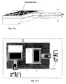
- Fig. 6 shows a block diagram of a proposed according to the invention Selection principle for the combination of piezoelectric excitation and the piezoresistive readout.
- the phase difference between current and voltage must be with compensated self-capacitance and stray capacitance of the piezoelectric Layer be equal to 0 °.
- This may e.g. by a phase comparator with Frequency tracking of a voltage controlled oscillator (VCO) achieved become.
- VCO voltage controlled oscillator
- a second possibility consists in the circuit in the feedback branch in a vibratory system. The amplitude stability of Prongs Z1 and Z2 are adjusted by tracking the piezo voltage ensures the piezoelectric current.
- the output signal of the piezoresistive sensor will after a preamp and a bandpass filtering with the order 90 ° out of phase excitation signal of the tines multiplied.
- the multiplier is a low-pass band limiting device downstream. If necessary, it is possible to use the sensor as a tethered Version interpreted. This can increase sensitivity and resolution become.
- the silicon wafers used can also be supplemented by epitaxial growth of silicon.
- the specified materials can also buried p / n transitions for the 'electrochemical etch stop' are used;
- wing structures or booms for targeted damping or for electrostatic excitation / readout can be used as e.g. in Fig.10a is shown.
- the tines can also with a predetermined profile such.
- the cross section of the torsion bar T can, for example, as shown in FIG 7f shown to be formed as a hollow profile.
- the geometry, in particular the length, the tuning fork base can adapt to the given material properties be adjusted.
- a tuning fork tines can be used accordingly Figure 7c be provided with a mass M for later trimming.
- the mechanical crosstalk can be achieved by the appropriate placement of the piezoresistive Element on the torsion bar are minimized. Furthermore can by applying one or more piezoresistors, the the longitudinal or transverse PR effect for measuring the bending stress use in the suspension of the tuning fork, the mechanical crosstalk be measured.
- thermomechanical excitation via implanted resistors or thin film resistors is a magnetic excitation represented by a magnetostrictive thin film TbFe, SmFe, (TbDy) Fe.
- electrostatic excitation of Fig. 9c with excitation electrodes is possible.
- electromagnetic excitation e.g. via a conductor loop in the homogeneous magnetic field and in Fig. 9e e.g. over a coil in the Inhomogeneous magnetic field parallel to the tine movement reproduced.
- shape memory materials in an arrangement such as come to use according to Figure 9a.
- all of the actuator thin films used may be on one or the other be applied to both tines of the tuning fork.
- the readout can be optically, for example by a reflective Layer and beam deflection angle, or through a layer whose optical properties depend on the mechanical stress in the layer or by a layer which according to FIG. 10b is part of a Michelson interferometer is done.
- FIGS. 11 a-d Various integration variants are presented with reference to FIGS. 11 a-d.
- the sensor electronics or parts of the electronics on the Chip to be integrated with the rotation rate sensor.
- at least two yaw-rate sensors are provided for simultaneous purposes Integrated measurement of several components of angular velocity.
- a DRS 1 and at least an acceleration sensor (BS) integrated on the same chip are provided.
- the BS may be sensitive to the wafer level or perpendicular to the wafer plane be arranged.
- Such an integrated microsystem may e.g. in an anti-spinner system for measuring yaw rate and lateral acceleration be used.
- the microsystem consists of at least two DRSs and at least two acceleration sensors and the associated electronics for precise determination of the two components of angular velocity and the acceleration in wafer plane as well as the acceleration perpendicular to.
- the natural frequencies of the excitation and the readout mode is set to be outside of the field of application the sensor relevant interference spectrum are.
- a frequency-selective Measurement according to the Lockin principle, thus results in an increased Insensitivity to lateral acceleration.
Abstract
Description
Die Erfindung betrifft einen mikromechanischen Drehratensensor, bei dem Teile aus Silizium, Siliziumverbindungen oder Silizium/Glasverbindungen oder anderen Halbleitermaterialien mit Techniken der Mikromechanik herausstrukturiert sind.The invention relates to a micromechanical rotation rate sensor in which Parts of silicon, silicon compounds or silicon / glass compounds or other semiconductor materials with micromechanical techniques out structured are.
Die Anwendungsgebiete solcher Drehratensensoren sind sehr vielfältig. So können im Bereich der Kraftfahrzeugtechnik die Gier-, Nick-, und Rollgeschwindigkeit als Schlüsselgröße für Fahrdynamikregelungssysteme (ABS, ADS, ASS, ASR, u.a.), für Navigationssysteme als Ergänzung zum GPS sowie für die Messung der Winkelgeschwindigkeit bewegter Teile eines Kfz zueinander bestimmt werden. In der Raumfahrt können solche Systeme als gewichtund platzsparende Inertialkomponenten (Trägheitsplattform), zur Stabilisierung der Fokalebene optischer Beobachtungsinstrumente von Satelliten und zur Messung und Stabilisierung von (ungedämpften) Schwingungen elastischer Komponenten Verwendung finden.The fields of application of such rotation rate sensors are very diverse. So can in the field of automotive technology, the yaw, pitch, and roll speed as a key variable for vehicle dynamics control systems (ABS, ADS, ASS, ASR, etc.), for navigation systems as a supplement to the GPS as well for measuring the angular velocity of moving parts of a vehicle to each other be determined. In aerospace, such systems can be weighted and weighted Space-saving inertial components (inertial platform), for stabilization the focal plane of optical observation instruments of satellites and the Measurement and stabilization of (undamped) vibrations more elastic Components are used.
Bei der Luftfahrt kann die Messung und Regelung der relativen Bewegung verschiedener Flugzeugkomponenten zueinander (adaptiver Flügel) erfolgen; ferner besteht Verwendungsmöglichkeit bei der Bahnstabilisierung und Navigation von Flugkörpern.In aviation, the measurement and regulation of the relative movement of different Aircraft components to each other (adaptive wing) done; further There is a possibility of use in railway stabilization and navigation of missiles.
Bei der Bahntechnik kann Gier- und Rollwinkel der Wagen mit Einzelradaufhängung (vgl. Pendolino), also der Istwert zur Regelung der optimalen Kurveneinfahrtsgeschwindigkeit gemessen werden.In the railway technology can yaw and roll angle of the car with independent suspension (see Pendolino), ie the actual value for the regulation of the optimal cornering speed be measured.
In der Automatisierungstechnik können Roboterbewegungen überwacht sowie Roboterkomponenten gesteuert werden. In automation technology, robot movements can be monitored as well Robot components are controlled.
Im allgemeinen Maschinenbau sind solche Komponenten für die Vibrationsmessung (evtl. Active Vibration Control), besonders für die Messung derjenigen Komponente der Impedanz schwingender elastischer Strukturen, die von dem "Drehanteil" der Bewegung herrührt, nützlich. Hier ist besonders die Miniaturisierung (geringes Gewicht und geringer Platzbedarf) entscheidend.In general engineering, such components are for vibration measurement (possibly Active Vibration Control), especially for the measurement of those Component of impedance-vibrating elastic structures produced by the "rotational part" of the movement, useful. Here is especially the miniaturization (low weight and small footprint) crucial.
Schließlich finden sich beispielsweise in der Medizintechnik Anwendungsmöglichkeiten so zu Beispiel beim Monitoring von Patienten durch Messung deren Bewegungen, bei der Steuerung von chirurgischen Instrumenten (minimal invasive Chirurgie) und der Steuerung von RollstühlenFinally, there are applications, for example, in medical technology For example, when monitoring patients by measurement their movements, in the control of surgical instruments (minimally invasive surgery) and the control of wheelchairs
Die zahlreichen Anwendungsmöglichkeiten haben bereits zu zahlreichen Vorschlägen für Drehratensensoren geführt.The numerous applications already have numerous suggestions guided for rotation rate sensors.
Verschiedene Prinzipien zur Messung der Drehrate wurden inzwischen auch miniaturisiert, um kostengünstig gefertigt zu werden und um für Anwendungen in Videokameras, Fahrzeugen oder anderen bewegten Objekten in Frage zu kommen. Es sind bereits Realisierungen in Metall mit piezoelektrischer Aktorik und Sensorik, in Quarz, in kristallinem Silizium und in Polysilizium bekannt.Various principles for measuring the rate of rotation have become synonymous miniaturized to be inexpensively manufactured and used for applications in video cameras, vehicles or other moving objects in question come. There are already realizations in metal with piezoelectric actuators and sensors, in quartz, in crystalline silicon and in polysilicon.
So sind in DE 42 28 795 A1 (Bosch), EP 05 72 976 A1 (Canon), WO 93/14409 (Sunstrand) Systeme beschrieben, bei denen einer oder mehrere Beschleunigungssensoren (BS) auf schwingenden Strukturen angebracht sind, und die bei einer Drehung des Systems resultierende Coriolisbeschleunigung messen. Als Nachteil ist dabei zu sehen, daß die Starrheit der Struktur, auf der sich die beiden Sensoren befinden, nicht oder sehr schwierig zu gewährleisten ist. Ferner ist das Übersprechen der Anregungsbewegung auf die Sensorkomponente nicht auszuschalten, insbesondere dann nicht, wenn man nur jeweils einen BS für jede Richtung verwendet.Thus, in DE 42 28 795 A1 (Bosch), EP 05 72 976 A1 (Canon), WO 93/14409 (Sunstrand) systems are described in which one or more accelerometers (BS) are mounted on vibrating structures, and measure the Coriolis acceleration resulting from a rotation of the system. The disadvantage is to see that the rigidity of the structure on which the two sensors are located, not or very difficult to ensure. Furthermore, the crosstalk of the excitation movement to the sensor component not switch off, especially not if you only one each BS used for each direction.
Die Druckschriften DE 35 09 948 A1 (Draper) und EP 0 422 280 A2 (Draper) beschreiben Drehratensensoren, deren Geometrie an eine miniaturisierte, kardanische Aufhängung (Gimbal) angelehnt ist. Wird das Gesamtsystem um eine geeignete Achse gedreht, so koppelt eine Drehschwingung um die Aufhängung des äußeren Rahmens an eine Drehschwingung um die Aufhängung des inneren Rahmens (und/oder umgekehrt). Hier ist als Nachteil zu sehen, daß die angegebene dreidimensionale Geometrie zur optimalen Sensorfunktion die Erzeugung mechanisch spannungsfreier Strukturen bzw. Strukturen mit definierten Verspannungen erfordert, was sehr schwierig zu realisieren ist. Zur Erzielung eines ausreichend großen Meßeffekts ist eine besondere Anordnung der trägen Masse auf dem Sensor notwendig, diese muß symmetrisch zu einer Achse senkrecht zur Waferebene auf der kardanischen Struktur angeordnet sein. Die technologische Realisierung eines solchen Aufbaus ist sehr problematisch, d.h. die Herstellung der Sensoren im Batchprozess mit dem Ziel großer Stückzahlen ist sehr kostenintensiv.The documents DE 35 09 948 A1 (Draper) and EP 0 422 280 A2 (Draper) describe gyroscopes whose geometry corresponds to a miniaturized gimbal Suspension (gimbal) is ajar. Will the overall system be one rotated suitable axis, so couples a torsional vibration around the suspension the outer frame to a torsional vibration about the suspension of the inner Frame (and / or vice versa). Here is to be seen as a disadvantage that the specified three-dimensional geometry for optimal sensor function the production mechanically stress-free structures or structures with defined Tensioning is required, which is very difficult to realize. To achieve a sufficiently large Meßeffekts is a special arrangement of inertial mass on the sensor necessary, this must be symmetrical to a Axis arranged perpendicular to the wafer plane on the gimbal structure his. The technological realization of such a structure is very problematic i.e. the production of the sensors in the batch process with the goal big Numbers is very expensive.
Aus WO 93/05400 (BEI-Electronics) ist ein elektrostatisch bzw. elektromagnetisch angeregter Drehratensensor bekannt, der aus einer Scheibe besteht, welche in der Waferebene kleine periodische Drehbewegungen ausrührt. Eine Drehung des Systems um eine Achse parallel zur Waferebene verursacht eine Verkippung der Scheibe bezüglich ihrer Bewegungsebene. Diese Verkippung wird durch piezoresistive Sensoren in den vier elastischen Aufhängungen der Scheibe gemessen. Die Nachteile liegen darin, daß dieser Sensor nur unter großen Aurwand mechanisch spannungsfrei herzustellen ist und daß die Verkippung der Scheibe in einem gedrehten Koordinatensystem bewirkt, daß die Regelung der kapazitiven Anregung der periodischen Drehbewegung der Scheibe sehr aufwendig wird.From WO 93/05400 (BEI-Electronics) is an electrostatic or electromagnetic excited rotation rate sensor known, which consists of a disc, which stirs out small periodic rotational movements in the wafer plane. A Rotation of the system about an axis parallel to the wafer plane causes a Tilt the disc with respect to its plane of motion. This tilt is powered by piezoresistive sensors in the four elastic suspensions of the Disc measured. The disadvantages are that this sensor only under large auric wall is mechanically stress-free manufacture and that the tilting the disc in a rotated coordinate system causes the Control of the capacitive excitation of the periodic rotation of the Disc is very expensive.
Die Druckschrift EP 0 519 404 A1(Honda) beschreibt einen Gasfluß-Sensor im Anemometerprinzip, bei dem der Effekt einer Drehrate über die Änderung des Differentialwiderstandes eines Leiterpaares gemessen wird. Dieses Leiterpaar befindet sich in der Wand eines gasdurchflossenen Si-Röhrchens und mißt die Richtungsänderung des Gasflusses aufgrund der Corioliskraft. Die Nachteile sind hier darin zu sehen, daß das System für die Versorgung und Regelung des Gases zusätzlich Aktorik (z.B. Ventile und/oder Pumpen) sowie weitere Peripherie für die Gasbevorratung und -zuleitung etc. benötigt. Das Vorhandensein dieser Komponenten wird in diesem Patent vorausgesetzt. Ferner ist durch den Einsatz eines Gases eine hohe Temperaturempfindlichkeit zu erwarten.The document EP 0 519 404 A1 (Honda) describes a gas flow sensor in the Anemometer principle in which the effect of a rotation rate over the change of the Differential resistance of a pair of conductors is measured. This pair of conductors is located in the wall of a gas-carrying Si tube and measures the Direction change of the gas flow due to the Coriolis force. The disadvantages can be seen here in the fact that the system for the supply and regulation of the Gas additionally actuators (such as valves and / or pumps) and other peripherals needed for gas storage and supply etc. The presence these components are presupposed in this patent. Furthermore, by the Use of a gas to expect a high temperature sensitivity.
Zu den bereits miniaturisierten Geometrien und Funktionsweisen gehören auch verschiedene Arten von Stimmgabelsensoren zur Messung der Drehrate. Sie sind beispielsweise aus: EP 0 574 143 A1 (Lucas), WO 93/05401 (Draper) , DE 40 22 485 A1, WP 92/01941 (Bosch) DE 42 28 795 A1 und DE 40 41 582 A1(Bosch) bekannt. Bei sämtlichen darin beschriebenen Stimmgabelsensoren werden die Zinken zu Schwingungen parallel zur Waferebene angeregt. Bringt man das Sensorsystem in ein gedrehtes Koordinatensystem, so bewirkt das eine Biegung der Zinken in einer Ebene senkrecht zur Anregungsrichtung und/oder eine Torsion der Zinkenaufhängung.The already miniaturized geometries and modes of operation also include various types of tuning fork sensors for measuring the rate of rotation. They are known, for example, from EP 0 574 143 A1 (Lucas), WO 93/05401 (Draper), DE 40 22 485 A1, WO 92/01941 (Bosch) DE 42 28 795 A1 and DE 40 41 582 A1 (Bosch) , In all of the tuning fork sensors described therein, the tines are excited to vibrate parallel to the wafer plane. Bringing the sensor system in a rotated coordinate system, this causes a bending of the tines in a plane perpendicular to the direction of excitation and / or a torsion of the tine suspension.
Bei den Schriften WO 93/05401 (Draper), DE 40 22 485 A1, WP 92/01941 (Bosch) und DE 40 41 582 A1(Bosch) handelt es sich um doppelt (beidseitig) aufgehängte Stimmgabelsensoren. Man muß daher erwarten, daß diese Sensoren eine erhebliche Temperaturempfindlichkeit aufweisen. Die in den meisten Ausführungsbeispielen vorgeschlagene elektrostatische Anregung der Zinken sowie die Auslesung des Signals implizieren Nichtlinearitäten, die zur einem erheblichen Regelungsaufwand führen. Bei den Ausführungsbeipielen aus WO 93/05401 ist zusätzlich eine mechanisch spannungsfreie Strukturierung problematisch.In the documents WO 93/05401 (Draper), DE 40 22 485 A1, WP 92/01941 (Bosch) and DE 40 41 582 A1 (Bosch) are double (both sides) suspended tuning fork sensors. One must therefore expect that these sensors have a significant temperature sensitivity. The most in the Embodiments proposed electrostatic excitation of the tines as well as the readout of the signal imply nonlinearities that are for one lead to considerable regulatory effort. In the Ausführungsbeipielen from WO 93/05401 is additionally a mechanically stress-free structuring problematic.
Ein einseitig aufgehängter Stimmgabelsensor mit piezoresistiver Auslesung der Torsion der Stimmgabelaufhängung ist aus EP 0574 143 A1 (Lucas) bekannt. Die Stimmgabel wird elektrostatisch über eine Interdigitalstruktur zu Schwingungen in der Waferebene angeregt. Aufgrund der geringen Strukturtiefe des Sensorelementes (senkrecht zur Waferebene) ist es hier problematisch die Steifigkeit der Stimmgabelbasis und der Zinken in dieser Richtung zu gewährleisten. Diese Steifigkeit ist aber notwendig, um eine Signalauslesung der Drehrate über die Torsion der Stimmgabelaufhängung zu realisieren.A single-sided suspended tuning fork sensor with piezoresistive readout of the Torsion of the tuning fork suspension is known from EP 0574 143 A1 (Lucas). The tuning fork is electrostatically oscillated via an interdigital structure excited at the wafer level. Due to the small structural depth of the Sensor element (perpendicular to the wafer plane), it is problematic here To ensure rigidity of the tuning fork base and tines in this direction. However, this rigidity is necessary to a signal reading of the Turn rate about the twist of the tuning fork suspension to realize.
Es ist das Ziel der Erfindung, ein miniaturisiertes und preiswert in Massenherstellung zu fertigendes System zu schaffen, das zur Messung der Drehrate (Winkelgeschwindigkeit) bewegter Körper in allen Bereichen der Technik verwendet werden kann.It is the object of the invention, a miniaturized and inexpensive in mass production to create the system to be used for measuring the rate of rotation (Angular velocity) moving body in all areas of technology can be used.
Diese Aufgabe wird durch die Merkmale gemäß dem kennzeichnenden Teil des Hauptanspruches gelöst.This object is achieved by the features according to the characterizing part solved the main claim.
Durch die erfindungsgemäße Lösung ergeben sich insbesondere folgende Vorteile: The solution according to the invention gives rise in particular to the following advantages:
Die Miniaturisierung kann stark vorangetrieben werden, da die Lösung robust gegen Schock durch geringe Masse und symmetrischen Aufbau und kostensparend, gewichtsparend, platzsparend und energiesparend ist;The miniaturization can be driven forward, because the solution is robust against shock due to low mass and symmetrical construction and cost saving, saves weight, saves space and saves energy;
Das Herstellungsverfahren erlaubt über Batchprozesse hohe Stückzahlen und gute Reproduzierbarkeit und ist kostengünstig. Durch die CMOS-kompatible Herstellung, ist auch die Voraussetzung für die monolithische Integrierbarkeit mit der Sensorelektronik oder Teilen davon sowie anderen geeigneten mikromechanischen Komponenten gewährleistet.The manufacturing process allows high volumes and batch processes good reproducibility and is inexpensive. Through the CMOS compatible Production is also the prerequisite for monolithic integrability with the sensor electronics or parts thereof as well as other suitable micromechanical Components guaranteed.
Die monolithische Integrierbarkeit mit der Sensorelektronik oder mit Teilen von dieser zu einem robusten, preiswerten Drehratensensor z.B. mit Beschleunigungssensoren zu Mikroinertialkomponenten ist besonders vorteilhaft.The monolithic integrability with the sensor electronics or with parts from this to a robust, low-cost rotation rate sensor, e.g. with acceleration sensors to microinertial components is particularly advantageous.
Weitere spezielle Vorteile der vorgeschlagenen Sensorgeometrie und des entsprechenden Sensorherstellungsverfahrens für die Zinken in der Waferebene sind in der Designfreiheit der Zinken, in genügend Fläche für die Aktorik (z.B. piezoelektrische Aktorik, kapazitive Aktorik, etc., s.u.), in präziser Fertigung der Zinkengeometrie in der Waferebene durch Verwendung von photolithographischen Verfahren, im hochgenauen Einstellen der Zinkendicke durch die Nutzung von vergrabenen Ätzstoppschichten unter Verwendung von SiliconOnInsulator-Material (hergestellt z.B. durch bekannte BESOI- oder SIMOX-Verfahren) und in der Trimmbarkeit auf der Zinkenfläche su sehen.Further special advantages of the proposed sensor geometry and the corresponding sensor manufacturing process for the tines in the wafer level are in the design freedom of the tines, in sufficient area for the actuators (eg piezoelectric actuators, capacitive actuators, etc., see below), in precise production of the tine geometry in the See wafer level by using photolithographic processes, in the highly accurate setting of the zinc thickness through the use of buried etch stop layers using SiliconOnInsulator material (prepared for example by known BESOI or SIMOX process) and in the trimmability on the tine surface see below.
Durch die Ankopplung an die Torsion der Stimmgabelaufhängung ist die Anregungsbewegung von der Auslesebewegung getrennt.By coupling to the torsion of the tuning fork suspension is the excitation movement separated from the readout movement.
Als Vorteile im Vergleich zu Metall- und Quarzsensoren ist zu nennen, daß die notwendige, hybride Integration der Quarzkomponente mit der Elektronik kein so hohes Kostenreduzierungspotential in der Herstellung wie die Siliziumsensoren erlaubt.As advantages compared to metal and quartz sensors is to mention that the necessary, hybrid integration of the quartz component with the electronics no as high cost reduction potential in the production as the silicon sensors allowed.
Weitere Einzelheiten der Erfindung ergeben sich aus der Beschreibung, in der anhand der Zeichnung mehrere Ausführungsbeispiele erörtert sind. Es zeigen:
- Fig. 1a-c
- eine dreidimensionale Darstellung des ersten Ausführungsbeispiels,
und zwar
- a) die Prinzipdarstellung
- b) die Darstellung der Anregungsmode und
- c) die Darstellung der Auslesungs- oder Torsionsmode
- Fig. 2
- eine schematische Darstellung des Querschnitts des ersten Ausführungsbeispiels in der Variante A
- Fig.3
- eine schematische Aufsicht auf den Gegenstand der Erfindung,
- Fig.4
- einen schematischen Querschnitt A-A' durch den Gegenstand von Fig. 3,
- Fig.5
- schematisch den Querschnitt des ersten Ausführungsbeispiels in der Variante B
- Fig.6
- ein Blockschaltbild zur Auswertung des ersten Ausführungsbeispiels
- Fig. 7 a-c
- Konstruktive Varianten für die Geometrie zur Optimierung der Abstimmung
und zwar
- a) U-Profil
- b) Hohlprofil des Torsionsbalkens
- c) Zinken mit Trimmasse
- Fig. 8 a-b
- Varianten für die Bildung von Differenzsignalen und zwar
- a) entgegengesetzte Anordnung in zwei Ätzgruben und
- b) entgegengesetzte Anordnung in einer Ätzgrube
- Fig. 9. a-e:
- Varianten für die Anregung, und zwar
- a) Thermomechanisch (Formgedächtnis: analoger Aufbau),
- b) Magnetostriktiv,
- c) Elektrostatisch,
- d) Elektromagnetisch im homogenen B-Feld und
- e) Elektromagnetisch im inhomogenen B-Feld
- Fig. 10 a-c
- Varianten für den Auslesemechanismus, und zwar
- a) Elektrostatisch,
- b) Optisch (Interferometer) und
- c) Piezoelektrisch.
- Fig. 11 a-d
- Varianten für die monolithische Integration (insb. DRS und BS
mit der empfindlichen Richtung senkrecht zur Waferoberfläche)
und zwar
- a) Drehratensensor mit Signverarbeitungselektronik,
- b) zwei Drehratensensoren für unterschiedliche Achsen,
- c) ein Drehratensensor und ein Beschleunigungssensor und
- d) zwei Drehratensensoren und zwei Beschleunigungssensoren.
- Fig. 1a-c
- a three-dimensional view of the first embodiment, and that
- a) the schematic diagram
- b) the representation of the excitation mode and
- c) the representation of the readout or torsional mode
- Fig. 2
- a schematic representation of the cross section of the first embodiment in the variant A.
- Figure 3
- a schematic plan view of the subject matter of the invention,
- Figure 4
- a schematic cross-section AA 'through the subject of Fig. 3,
- Figure 5
- schematically the cross section of the first embodiment in the variant B.
- Figure 6
- a block diagram for evaluation of the first embodiment
- Fig. 7 ac
- Constructive variants for the geometry to optimize the tuning and indeed
- a) U-profile
- b) hollow profile of the torsion bar
- c) tines with trimmasse
- Fig. 8 from
- Variants for the formation of differential signals and that
- a) opposite arrangement in two etching pits and
- b) opposite arrangement in an etching pit
- Fig. 9. ae:
- Variants for the stimulation, namely
- a) thermomechanical (shape memory: analogue structure),
- b) magnetostrictive,
- c) electrostatic,
- d) Electromagnetic in the homogeneous B field and
- e) Electromagnetic in the inhomogeneous B field
- Fig. 10 ac
- Variants for the read-out mechanism, namely
- a) electrostatic,
- b) Optical (interferometer) and
- c) Piezoelectric.
- Fig. 11 ad
- Variants for the monolithic integration (esp. DRS and BS with the sensitive direction perpendicular to the wafer surface) namely
- a) rotation rate sensor with sign processing electronics,
- b) two yaw rate sensors for different axes,
- c) a rotation rate sensor and an acceleration sensor and
- d) two rotation rate sensors and two acceleration sensors.
Zunächst wird das Funktionsprinzip anhand der Figur 1 beschrieben.First, the principle of operation will be described with reference to FIG.
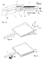
Eine Möglichkeit zur Messung der Winkelgeschwindigkeit (Drehrate), die im folgenden anhand der vorliegenden Sensorkonfiguration näher beschrieben wird, besteht in der Ausnutzung des Corioliseffekts. In den Figuren 1a-c ist die Geometrie des Sensors dargestellt und das zugrundeliegende Funktionsprinzip in stark vereinfachter Form veranschaulicht.A possibility to measure the angular velocity (rotation rate), which in described in more detail below with reference to the present sensor configuration is in the exploitation of the Coriolis effect. In the figures 1a-c is the Geometry of the sensor shown and the underlying operating principle illustrated in a simplified form.
Der Sensor besteht aus einer Stimmgabel S mit Doppelzinken Z1 und Z2, deren Fußpunkt, die Basis B, an einem Torsionsbalken T hängt, der selber wiederum in einer massiven Supportstruktur mündet, die vom oberen Wafer OW und dem unteren Wafer UW gebildet wird. Auf dem oberen Zinken Z1 der Stimmgabel S ist eine Aktorschicht bzw. ein Aktorelement A zur Zinkenanregung aufgebracht. Der Torsionsbalken T trägt eine sensitive Schicht S zur Signalerfassung, d.h. zur Torsionsmessung.The sensor consists of a tuning fork S with double tines Z1 and Z2, whose Base point, the base B, hangs on a torsion bar T, which in turn opens in a massive support structure, the upper wafer OW and the lower wafer UW is formed. On the upper teeth Z1 of the Tuning fork S is an actuator layer or an actuator element A for tine excitation applied. The torsion bar T carries a sensitive layer S for signal detection, i.e. for torsion measurement.
Grundvoraussetzung zur Ausnutzung des Corioliseffekts ist die Anregung einer Stimmgabelschwingung. Die entsprechende Anregungs- oder auch Stimmgabelmode ist schematisch in Fig.lb dargestellt. Bringt man den derart schwingenden Sensor in ein System, das sich um die Längsachse des Torsionsbalkens (x-Achse) mit einer Drehgeschwindigkeit ω dreht, so wirkt aufgrund der gegenphasigen Schwingung der Zinken Z1 und Z2, die senkrecht zur Waferoberfläche (x-y-Ebene) erfolgt, ein Drehmoment D um die x-Achse auf die Struktur. Dieses periodische Drehmoment führt zu einer Drehschwingung des Torsionsbalkens T. Die entsprechende Torsions- oder auch Auslesungsmode ist in Fig. 1c dargestellt. Die Amplitude der Drehschwingung ist der zu messenden Drehrate und der Schnelle v der Zinken direkt proportional.The basic prerequisite for the utilization of the Coriolis effect is the excitation of a tuning fork vibration. The corresponding excitation or tuning fork mode is shown schematically in Fig.lb. Bringing the thus oscillating sensor in a system that rotates about the longitudinal axis of the torsion bar (x-axis) with a rotational speed ω, so acts due to the antiphase oscillation of the prongs Z1 and Z2, which is perpendicular to the wafer surface (xy plane) , a torque D about the x-axis on the structure. This periodic torque leads to a torsional vibration of the torsion bar T. The corresponding torsional or readout mode is shown in Fig. 1c. The amplitude of the torsional vibration is directly proportional to the rate of rotation to be measured and the speed v of the tines.
Eine von vielen Möglichkeiten zur Bestimmung der Drehrate ω besteht, wie in Figur 1a angedeutet, in der piezoresistiven Messung der durch die Drehschwingung im Torsionsbalken induzierten, mechanischen Schubspannungen. Um ein möglichst großes Meßsignal zu erhalten, müssen die Eigenfrequenzen der Anregungs- und der Auslesungsmode im Rahmen einer geometrischen Optimierung aufeinander abgestimmt werden. Die Anregung selbst sollte möglichst in Resonanz erfolgen. Die Güte ( Q-Faktor) der Auslesungsmode sollte aus Gründen der Signalmaximierung möglichst hoch sein. Die Drehrichtung kann aus der Phasenlage der Torsionsschwingung bestimmt werden.One of many ways to determine the rate of rotation ω is as in Figure 1a indicated, in the piezoresistive measurement by the torsional vibration in the torsion beam induced, mechanical shear stresses. In order to obtain the largest possible measuring signal, the natural frequencies must the excitation and the readout mode as part of a geometric optimization be coordinated with each other. The suggestion itself should be as possible in resonance. The quality (Q-factor) of the readout mode should be as high as possible for the sake of signal maximization. The direction of rotation can be determined from the phase angle of the torsional vibration.
Im Folgenden wird ein erstes Ausführungsbeispiel in zwei Varianten beschrieben. Die beiden Varianten unterscheiden sich dadurch, daß in der ersten Variante A die Dicke der Stimmgabelaufhängung gleich der Dicke der Stimmgabel-Struktur ist. (Fig. 1-4).In the following, a first embodiment will be described in two variants. The two variants differ in that in the first variant A is the thickness of the tuning fork suspension equal to the thickness of the tuning fork structure is. (Figures 1-4).
Bei der Variante B hingegen ist die Dicke der Stimmgabelaufhängung kleiner als die Dicke der Stimmgabel-Struktur, d.h. es erfolgt eine Einkerbung des Torsionsbalkens T (Fig. 5).In variant B, however, the thickness of the tuning fork suspension is smaller as the thickness of the tuning fork structure, i. There is a notch of the Torsion bar T (Figure 5).
Die Stimmgabel (Sensormittelteil) besteht aus zwei Si-Wafern. Der Aufbau ist aus Basis- und Deckwafer (aus Silizium und/oder Glas) gestapelt und so an das Mittelteil gebondet, daß die Sensorkavität evakuiert werden kann (Fig.4). Der Bondrahmen ist durch ein geeignetes Dotierprofil im Bondrahmenbereich vakuumdicht elektrisch untertunnelt (Fig.4). Die Anregung eines Zinkens erfolgt über eine piezoelektrische Dünnschicht A z.B. aus AIN, ZnO2, PZT o.ä. (Fig.1-4). Die piezoelektrische Dünnschicht A ist unten über dotiertes Silizium (Fig.4) oder eine elektrisch leitende Dünnschicht, oben über eine elektrisch leitende Dünnschicht kontaktiert. Die Auslesung der Schubspannung auf der Oberfläche des Torsionsbalkens T (bzw. der Aufhängung der Stimmgabel) erfolgt piezoresistiv; dazu ist eine vierseitige Kontaktierung des Piezowiderstandes notwendig (Fig.3). Insgesamt arbeitet das System als resonantes Aktor-Sensor-System (Fig.1). The tuning fork (sensor middle part) consists of two Si wafers. The assembly is stacked of base and top wafers (of silicon and / or glass) and bonded to the central part so that the sensor cavity can be evacuated (Figure 4). The bonding frame is electrically tunnelled through a suitable doping profile in the bonding frame region in a vacuum-tight manner (FIG. 4). The excitation of a zinc is carried out via a piezoelectric thin film A, for example, AIN, ZnO 2 , PZT or the like. (Fig.1-4). The piezoelectric thin film A is contacted at the bottom via doped silicon (FIG. 4) or an electrically conductive thin film, at the top via an electrically conductive thin film. The reading of the shear stress on the surface of the torsion bar T (or the suspension of the tuning fork) is piezoresistive; For this purpose, a four-sided contacting of the piezoresistor is necessary (Fig.3). Overall, the system operates as a resonant actuator-sensor system (Figure 1).
Gemeinsam für Variante A und B gilt:Common for variant A and B is:
Es werden Herstellungsmethoden verwendet, die in der Halbleiterindustrie üblich und Stand der Technik sind, erweitert durch spezielle, mikromechanische Prozeßschritte auf der Basis von photolithographischer Vollwaferprozessierung im Batchprozeß.It uses manufacturing methods that are common in the semiconductor industry and state of the art, enhanced by special, micromechanical Process steps based on photolithographic Vollwaferprozessierung in the batch process.
Als Ausgangsmaterial werden zwei Siliziumwafer ggf. mit vergrabenen Dünnschichten verwendet, die für einen Ätzstopp beim naßchemischen, anisotropen Ätzen geeignet sind. Vorzugsweise kommt einkristallines Silizium (evt. auch Poly-Silizium) genannt SOI, mit frei wählbarer, jedoch symmetrischer Dicke in allen Dotierungstypen und Dotierkonzentrationen, vorzugsweise (100)-Silizum, zur Anwendung.The starting material is two silicon wafers with buried thin films if necessary used for an etch stop when wet chemical, anisotropic Etching are suitable. Preferably, monocrystalline silicon (possibly also Poly-silicon) called SOI, with freely selectable but symmetrical thickness in all doping types and doping concentrations, preferably (100) silicum, for use.
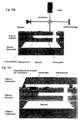
Fig. 6 zeigt anhand eines Blockschaltbildes ein gemäß der Erfindung vorgeschlagenes Ausleseprinzip für die Kombination der piezoelektrischen Anregung und der piezoresistiven Auslesung.Fig. 6 shows a block diagram of a proposed according to the invention Selection principle for the combination of piezoelectric excitation and the piezoresistive readout.
Damit eine resonante Anregung mit konstanter Amplitude der Zinken Z1 und Z2 erreicht wird, muß der Phasenunterschied zwischen Strom und Spannung bei kompensierter Eigenkapazität sowie Streukapazität der piezoelektrischen Schicht gleich 0° sein. Dieses kann z.B. durch einen Phasenkomperator mit Frequenznachführung eines spannungsgesteuerten Oszillators (VCO) erzielt werden. Eine zweite Möglichkeit besteht in der Schaltung in den Rückkoppelzweig in einem schwingungsfähigen System. Die Amplitudenstabilität der Zinken Z1 und Z2 wird durch Nachführen der Piezospannung in Abhängigkeit des Piezostroms gewährleistet. Das Ausgangssignal des piezoresistiven Sensors wird nach einer Vorverstärkung und einer Bandpaßfilterung mit dem um 90° phasenverschobenen Anregungssignal der Zinken multipliziert. Durch die phasensynchrone Gleichrichtung ist es möglich, das mechanische Übersprechen des Sensor zu vermindern. Dem Multiplizierer ist ein Tiefpaß zur Bandbegrenzung nachgeschaltet. Bei Bedarf ist es möglich, den Sensor als gefesselte Version auszulegen. Damit können Empfindlichkeit und Auflösung erhöht werden.So that a resonant excitation with constant amplitude of the prongs Z1 and Z2, the phase difference between current and voltage must be with compensated self-capacitance and stray capacitance of the piezoelectric Layer be equal to 0 °. This may e.g. by a phase comparator with Frequency tracking of a voltage controlled oscillator (VCO) achieved become. A second possibility consists in the circuit in the feedback branch in a vibratory system. The amplitude stability of Prongs Z1 and Z2 are adjusted by tracking the piezo voltage ensures the piezoelectric current. The output signal of the piezoresistive sensor will after a preamp and a bandpass filtering with the order 90 ° out of phase excitation signal of the tines multiplied. By the phase-synchronous rectification, it is possible the mechanical crosstalk of the sensor. The multiplier is a low-pass band limiting device downstream. If necessary, it is possible to use the sensor as a tethered Version interpreted. This can increase sensitivity and resolution become.
Im folgenden werden weitere Varianten für den Gegenstand der Erfindung vorgeschlagen. In the following, further variants of the subject invention are proposed.
Was das Ausgangsmaterial betrifft, so können die verwendeten Siliziumwafer auch durch epitaktisches Aufwachsen von Silizium ergänzt sein. Alternativ zu den angebenen Materialien können auch vergrabene p/n- Übergänge für den 'elektrochemischen Ätzstopp' verwendet werden;As far as the starting material is concerned, the silicon wafers used can also be supplemented by epitaxial growth of silicon. alternative to The specified materials can also buried p / n transitions for the 'electrochemical etch stop' are used;
Bezüglich der Geometrie können alternativ zum beschriebenen plattenförmigrechteckigen Aufbau der Zinken auch zusätzlich Flügelstrukturen oder Ausleger zur gezielten Dämpfung oder zu elektrostatischer Anregung/Auslesung verwendet werden wie es z.B. in Fig.10a dargestellt ist.With respect to the geometry may alternatively to the described plate-shaped rectangular Construction of the tines also additional wing structures or booms for targeted damping or for electrostatic excitation / readout can be used as e.g. in Fig.10a is shown.
Ferner können weitere konstruktive Maßnahmen zur Festlegung oder Veränderung der Frequenzen und Modenformen des Torsionsbalkens und der Zinken entsprechend Fig. 7. a-c getroffen werden, und zwar bezüglich der Geometrie der Zinken und des Torsionsbalkens oder abweichend von der rechteckigen Form in der Waferebene, z.B. in gabelförmiger Geometrie.Furthermore, further constructive measures can be taken to establish or change the frequencies and modes of the torsion beam and tines 7a-c, in terms of geometry the tines and the torsion bar or deviating from the rectangular Shape in the wafer plane, e.g. in fork-shaped geometry.
So können die Zinken auch mit einem vorgegebenen Profil wie z.B. einem U-Profil nach Figur 7a, mit einem Hohlprofil, einem H-Profil oder dergleichen ausgebildet werden.Thus, the tines can also with a predetermined profile such. a U-profile according to Figure 7a, with a hollow profile, an H-profile or the like be formed.
Ferner kann der Querschnitt des Torsionsbalkens T beispielsweise, wie in Figur 7f dargestellt, als Hohlprofil ausgebildet sein. Auch die Geometrie, insbesondere die Länge, der Stimmgabelbasis kann an die gegebenen Materialeigenschaften angepaßt werden. Ferner kann ein Stimmgabelzinken entsprechend Figur 7c mit einer Masse M zur späteren Trimmung versehen werden.Further, the cross section of the torsion bar T can, for example, as shown in FIG 7f shown to be formed as a hollow profile. Also the geometry, in particular the length, the tuning fork base can adapt to the given material properties be adjusted. Furthermore, a tuning fork tines can be used accordingly Figure 7c be provided with a mass M for later trimming.
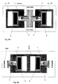
Das mechanische Übersprechen kann durch die geeignete Plazierung des piezoresistiven Elementes auf dem Torsionsbalken minimiert werden. Darüberhinaus kann durch das Aufbringen eines oder mehrerer Piezowiderstände, die den longitudinalen oder transversalen PR-Effekt zur Messung der Biegespannung in der Aufhängung der Stimmgabel nutzen, das mechanische Übersprechen gemessen werden.The mechanical crosstalk can be achieved by the appropriate placement of the piezoresistive Element on the torsion bar are minimized. Furthermore can by applying one or more piezoresistors, the the longitudinal or transverse PR effect for measuring the bending stress use in the suspension of the tuning fork, the mechanical crosstalk be measured.
Schließlich können mehrere Sensorelemente zur Bildung von Differenzsignalen, z.B. einem Offsetsignal, verwendet werden, wie den Figuren.8a und 8b zu entnehmen ist. Finally, several sensor elements for forming differential signals, e.g. an offset signal, as shown in Figures 8a and 8b can be found.
Auch für die Anregungs- und Auslesemechanismen sind verschieden Varianten möglich.Also for the excitation and read-out mechanisms are different variants possible.
Nach Fig. 9a kann thermomechanische Anregung über implantierte Widerstände oder Dünnschichtwiderstände erfolgen. In Figur 9b ist eine magnetische Anregung über eine magnetostriktive Dünnschicht TbFe,SmFe, (TbDy)Fe dargestellt. Auch elektrostatische Anregung nach Fig. 9c mit Anregungselektroden ist möglich. In Figur 9d ist elektromagnetische Anregung z.B. über eine Leiterschleife im homogenen Magnetfeld und in Figur 9e z.B. über eine Spule im inhomogenen Magnetfeld parallel zur Zinkenbewegung wiedergegeben. Schließlich können auch Formgedächtnismaterialien in einer Anordnung wie nach Figur 9a zur Anwendung kommen.According to Fig. 9a thermomechanical excitation via implanted resistors or thin film resistors. In Figure 9b is a magnetic excitation represented by a magnetostrictive thin film TbFe, SmFe, (TbDy) Fe. Also, electrostatic excitation of Fig. 9c with excitation electrodes is possible. In Figure 9d, electromagnetic excitation, e.g. via a conductor loop in the homogeneous magnetic field and in Fig. 9e e.g. over a coil in the Inhomogeneous magnetic field parallel to the tine movement reproduced. Finally, shape memory materials in an arrangement such as come to use according to Figure 9a.
Ferner können alle verwendeten Aktor-Dünnschichten jeweils auf einem oder beiden Zinken der Stimmgabel aufgebracht sein.Furthermore, all of the actuator thin films used may be on one or the other be applied to both tines of the tuning fork.
Auch bei der Auslesung sind mehrere Ausführungsformen möglich, die in den Figuren 10a-d vorgestellt werden.Also in the reading several embodiments are possible in the Figures 10a-d are presented.
So kann die Auslesung nach Fig. 10a elektrostatisch erfolgen. Dabei sind zusätzliche "Flügelflächen" sinnvoll.Thus, the reading of Fig. 10a can be done electrostatically. There are additional "Wing areas" makes sense.
Ferner kann die Auslesung optisch, und zwar beispielsweise durch eine reflektierende Schicht und Strahlablenkungswinkel, oder durch eine Schicht, deren optische Eigenschaften von der mechanischen Spannung in der Schicht abhängen oder durch eine Schicht, die entsprechend Figur 10b Bestandteil eines Michelson-Interferometers ist, erfolgen.Furthermore, the readout can be optically, for example by a reflective Layer and beam deflection angle, or through a layer whose optical properties depend on the mechanical stress in the layer or by a layer which according to FIG. 10b is part of a Michelson interferometer is done.
Schließlich ist nach Figur 10c eine piezoelektrische Auslesung möglich.Finally, according to Figure 10c, a piezoelectric readout is possible.
Prinzipiell ist es möglich, jede der genannten Ausführungsformen auch als gefesselten Sensor auszulegen. Allgemein gilt bei der Fesselung, daß die Torsionsbewegung durch entgegenwirkende Kräfte kompensiert wird. Die Stellgröße ist dann proportional zur Meßgröße. Bei diesem Verfahren wird eine höhere Empfindlichkeit und Auflösung als bei nicht gefesselten Sensoren erzielt. Unmittelbar möglich ist diese Kraftkompensation bei der elektrostatischen (Fig. 10a) sowie bei der piezoelektrischen (Fig. 10b) Ausführungsform, da die beschriebenen sensitiven Elemente sofort auch als Stellelemente verwendet werden können. Bei den übrigen Ausführungsformen werden die benötigten Stellelemente entsprechend ergänzt.In principle, it is possible for each of the embodiments mentioned also to be bound Interpret sensor. In general, in the bondage that the torsional movement is compensated by counteracting forces. The manipulated variable is then proportional to the measured variable. With this procedure becomes a higher Sensitivity and resolution achieved with unbelted sensors. Immediately possible this force compensation in the electrostatic (Fig. 10a) and in the piezoelectric (Fig. 10b) embodiment, since the described sensitive elements immediately used as adjusting elements can be. In the other embodiments, the required Adjusting elements added accordingly.
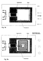
Anhand der Figuren 11 a-d sind verschiedene Integrationsvarianten vorgestellt.Various integration variants are presented with reference to FIGS. 11 a-d.
So kann nach Figur 11a die Sensorelektronik oder Teile der Elektronik auf dem Chip zusammen mit dem Drehratensensor integriert sein. Bei der Ausführungsform nach Figur 11b sind mindestens zwei Drehratensensoren zur gleichzeitigen Messung mehrerer Komponenten der Winkelgeschwindigkeit integriert. Bei der weiteren Ausführungsform nach Fig. 11c sind ein DRS 1 und mindestens ein Beschleunigungssensor (BS) auf demselben Chip integriert. Dabei kann der BS mit sensitiver Richtung in Waferebene oder senkrecht zur Waferebene angeordnet sein. Ein derartiges integriertes Mikrosystem kann z.B. in einem Anti-Schleuder-System zur Messung der Gierrate und der Querbeschleunigung eingesetzt werden.Thus, according to Figure 11a, the sensor electronics or parts of the electronics on the Chip to be integrated with the rotation rate sensor. In the embodiment According to FIG. 11b, at least two yaw-rate sensors are provided for simultaneous purposes Integrated measurement of several components of angular velocity. In the further embodiment according to FIG. 11c, a DRS 1 and at least an acceleration sensor (BS) integrated on the same chip. there For example, the BS may be sensitive to the wafer level or perpendicular to the wafer plane be arranged. Such an integrated microsystem may e.g. in an anti-spinner system for measuring yaw rate and lateral acceleration be used.
In Figur 11d besteht das Mikrosystem aus mindestens zwei DRS und mindestens zwei Beschleunigungssensoren sowie der dazugehörigen Elektronik zur präzisen Bestimmung der beiden Komponenten der Winkelgeschwindigkeit und der Beschleunigung in Waferebene sowie der Beschleunigung senkrecht dazu.In FIG. 11d, the microsystem consists of at least two DRSs and at least two acceleration sensors and the associated electronics for precise determination of the two components of angular velocity and the acceleration in wafer plane as well as the acceleration perpendicular to.
Durch Geometrieoptimierung werden die Eigenfrequenzen der Anregungs- und der Auslesungsmode so festgelegt, daß sie außerhalb des für das Anwendungsfeld des Sensors relevanten Störspektrums liegen. Im Rahmen einer frequenzselektiven Messung, nach dem Lockin-Prinzip, resultiert damit eine erhöhte Unempfindlichkeit gegenüber Querbeschleunigungen.By geometry optimization, the natural frequencies of the excitation and the readout mode is set to be outside of the field of application the sensor relevant interference spectrum are. As part of a frequency-selective Measurement, according to the Lockin principle, thus results in an increased Insensitivity to lateral acceleration.
Claims (24)
- Micromechanical gyrometer, wherein elements are constructed from silicon, silicon compounds or silicon/glass compounds or other semi-conductor materials using micromechanical techniques, characterisedin that the gyrometer is in the form of a tuning fork (S) which is fixed to semi-conductor wafers (OW, UW) by a tuning fork suspension, prongs (Z1, Z2) of the tuning fork (S) being located in planes parallel with the surface of the semi-conductor wafer (OW, UW),in that the prongs (Z1, Z2) can be excited to oscillate in a plane perpendicular to the wafer plane, andin that the gyrometer has a sensor element (S) which measures the angular velocity of rotation of the sensor about an axis parallel with the tuning fork suspension.
- Gyrometer according to claim 1, characterised in that the sensor element registers the torsion of the tuning fork suspension.
- Gyrometer according to claim 2, characterised in that the sensor element is produced from monocrystalline Si.
- Gyrometer according to claim 2, characterised in that the sensor element comprises other micromechanically constructable materials, such as, for example: poly-Si, SiC, silicon nitride, silicon dioxide, GaAs, quartz, AlN, PZT or metals.
- Gyrometer according to claim 3 or 4, characterised in that the tuning fork comprises two silicon wafers, optionally having embedded thin films, which are located between a base wafer and a top wafer, and in that the elements are bonded in such a manner that the cavity which surrounds the tuning fork can be evacuated.
- Gyrometer according to any one of the preceding claims, characterised in that the excitation of a prong of the tuning fork is effected by means of a piezoelectric thin film and the read-out of the transverse stress of the torsion beam is effected in a piezoresistive manner.
- Gyrometer according to any one of the preceding claims, characterised in that the cross-section of the torsion beam (T) is in the form of a hollow profile.
- Gyrometer according to any one of the preceding claims, characterised in that the cross-section of at least one prong (Z1) has a U-shaped profile.
- Gyrometer according to any one of the preceding claims, characterised in that at least one prong (Z1) is provided with a trimming weight.
- Gyrometer according to any one of the preceding claims, characterised in that the excitation of a prong of the tuning fork is effected thermomechanically by means of implanted heat resistors or thin-film heat resistors.
- Gyrometer according to any one of the preceding claims, characterised in that the excitation of a prong of the tuning fork is effected magnetically by means of a magnetostrictive thin film.
- Gyrometer according to any one of the preceding claims, characterised in that the excitation of a prong of the tuning fork is effected electrostatically by means of excitation electrodes.
- Gyrometer according to any one of the preceding claims, characterised in that the excitation of a prong of the tuning fork is effected electromagnetically by means of a conductor loop in a magnetic field.
- Gyrometer according to any one of the preceding claims, characterised in that the read-out of the transverse stress of the torsion beam is effected electrostatically.
- Gyrometer according to any one of the preceding claims, characterised in that the read-out of the transverse stress of the torsion beam is effected optically by means of a reflecting layer and deflection of a beam.
- Gyrometer according to claim 15, characterised in that the reflecting layer is a constituent-part of an interferometer.
- Gyrometer according to any one of the preceding claims, characterised in that the read-out of the transverse stress of the torsion beam is effected piezoelectrically.
- Gyrometer according to any one of the preceding claims, characterised in that at least elements of the control or read-out electronics system are integrated with the gyrometer on a chip.
- Gyrometer according to any one of the preceding claims, characterised in that it is integrated with at least one other gyrometer on a chip.
- Gyrometer according to any one of the preceding claims, characterised in that it is integrated with at least one acceleration sensor (BS) on a chip.
- Gyrometer according to any one of the preceding claims, characterised in that it is integrated with at least one acceleration sensor (BS) and one gyrometer (DRS) on a chip.
- Gyrometer according to any one of the preceding claims, characterised in that the thickness of the tuning fork suspension is equal to the thickness of the tuning fork structure.
- Gyrometer according to any one of the preceding claims, characterised in that the thickness of the tuning fork suspension is less than the thickness of the tuning fork structure.
- Gyrometer according to any one of the preceding claims, characterised in that it is in the form of a captive sensor in respect of torsion.
Applications Claiming Priority (3)
| Application Number | Priority Date | Filing Date | Title |
|---|---|---|---|
| DE19528961A DE19528961C2 (en) | 1995-08-08 | 1995-08-08 | Micromechanical rotation rate sensor (DRS) and sensor arrangement |
| DE19528961 | 1995-08-08 | ||
| PCT/EP1996/003412 WO1997006412A1 (en) | 1995-08-08 | 1996-08-02 | Micromechanical gyrometer |
Publications (2)
| Publication Number | Publication Date |
|---|---|
| EP0843809A1 EP0843809A1 (en) | 1998-05-27 |
| EP0843809B1 true EP0843809B1 (en) | 2003-02-12 |
Family
ID=7768880
Family Applications (1)
| Application Number | Title | Priority Date | Filing Date |
|---|---|---|---|
| EP96927661A Expired - Lifetime EP0843809B1 (en) | 1995-08-08 | 1996-08-02 | Micromechanical gyrometer |
Country Status (6)
| Country | Link |
|---|---|
| US (1) | US6474162B1 (en) |
| EP (1) | EP0843809B1 (en) |
| JP (1) | JP3950925B2 (en) |
| DE (2) | DE19528961C2 (en) |
| ES (1) | ES2189879T3 (en) |
| WO (1) | WO1997006412A1 (en) |
Cited By (1)
| Publication number | Priority date | Publication date | Assignee | Title |
|---|---|---|---|---|
| CN102507980A (en) * | 2011-11-02 | 2012-06-20 | 重庆理工大学 | Silicon micro two-dimension acceleration sensor based on self-resonant technology |
Families Citing this family (28)
| Publication number | Priority date | Publication date | Assignee | Title |
|---|---|---|---|---|
| DE19528961C2 (en) | 1995-08-08 | 1998-10-29 | Daimler Benz Ag | Micromechanical rotation rate sensor (DRS) and sensor arrangement |
| DE19812773C2 (en) | 1998-03-24 | 2002-11-14 | Conti Temic Microelectronic | Microsensor with a resonator structure |
| DE19831594C1 (en) * | 1998-07-14 | 2000-01-27 | Litef Gmbh | Micromechanical rotation rate sensor with coupling structure |
| DE19834535C1 (en) * | 1998-07-31 | 2000-03-16 | Daimler Chrysler Ag | Micromechanical rotation rate sensor to measure tilting by Coriolis force in container filled with liquid uses ductile membrane, supplied with piezoelectrically stimulated elements |
| DE19844686A1 (en) | 1998-09-29 | 2000-04-06 | Fraunhofer Ges Forschung | Micromechanical rotation rate sensor and manufacturing method |
| DE19845185B4 (en) * | 1998-10-01 | 2005-05-04 | Eads Deutschland Gmbh | Sensor with resonant structure and device and method for self-test of such a sensor |
| AUPQ081599A0 (en) * | 1999-06-08 | 1999-06-24 | Harris, Martin | Electrically operated tuning forks with novel geometry |
| DE10007868B4 (en) * | 2000-02-21 | 2010-02-18 | Robert Bosch Gmbh | Electronic control circuit |
| DE10010975B4 (en) * | 2000-03-07 | 2010-04-08 | Robert Bosch Gmbh | Micromechanical component |
| AU2001264661A1 (en) * | 2000-05-18 | 2001-11-26 | Stefaan De Schrijver | Micro-electrocmechamical sensor (mems) resonator |
| DE10139443A1 (en) * | 2001-08-10 | 2003-03-06 | Eads Deutschland Gmbh | Method and device for trimming sensors with vibrating structures |
| US6925413B2 (en) | 2001-12-14 | 2005-08-02 | Robert Bosch Gmbh | Method and system for detecting a spatial movement state of moving objects |
| DE10254163A1 (en) * | 2002-11-21 | 2004-06-03 | Eads Deutschland Gmbh | Micromechanical rotation rate sensor |
| JP2005098841A (en) * | 2003-09-25 | 2005-04-14 | Nippon Dempa Kogyo Co Ltd | Tuning fork shaped crystal oscillator, angular velocity sensor element, angular velocity sensor and method for manufacturing the tuning fork shaped crystal oscillator |
| DE10349014B4 (en) * | 2003-10-17 | 2014-01-09 | Austriamicrosystems Ag | Microelectromechanical rotation rate sensor |
| DE102005045379A1 (en) * | 2005-09-22 | 2007-03-29 | Eads Deutschland Gmbh | Rotary rate sensor for determining angular speed of article, has excitation oscillator with two prongs connected to base by bridge, which is arranged to displace excitation unit and prongs in lateral oscillation |
| DE102005045378A1 (en) * | 2005-09-22 | 2007-03-29 | Eads Deutschland Gmbh | Angular rate sensor for vehicle, has selection oscillator with tines that are arranged at distance and are connected with each other by base, where direct voltage is applied to excitation oscillator that is provided with electrodes |
| JP2007248328A (en) | 2006-03-17 | 2007-09-27 | Matsushita Electric Ind Co Ltd | Combined sensor |
| DE102006029443B3 (en) * | 2006-06-21 | 2008-01-31 | Siemens Ag | Sensor in micromechanical design for measuring the mass flow rate according to the Coriolis principle |
| US7808061B2 (en) * | 2006-07-28 | 2010-10-05 | Hewlett-Packard Development Company, L.P. | Multi-die apparatus including moveable portions |
| DE102007018834A1 (en) | 2007-04-20 | 2008-10-23 | Eads Deutschland Gmbh | Yaw rate sensor |
| GB2450157B (en) * | 2007-06-15 | 2011-12-21 | Baker Hughes Inc | System for determining an initial direction of rotation of an electrical submersible pump |
| DE102010018048A1 (en) | 2010-04-23 | 2011-10-27 | Northrop Grumman Litef Gmbh | Yaw rate sensor assembly and method of operating a yaw rate sensor assembly |
| JP5752803B2 (en) * | 2010-12-23 | 2015-07-22 | クゥアルコム・テクノロジーズ・インコーポレイテッド | RF device and method of tuning RF device |
| US9021887B2 (en) | 2011-12-19 | 2015-05-05 | Infineon Technologies Ag | Micromechanical semiconductor sensing device |
| US8991250B2 (en) * | 2012-09-11 | 2015-03-31 | The United States Of America As Represented By Secretary Of The Navy | Tuning fork gyroscope time domain inertial sensor |
| DE102018213513B4 (en) * | 2018-08-10 | 2024-03-21 | Zf Friedrichshafen Ag | Chassis component, method for producing a chassis component and wheel suspension for a motor vehicle |
| US11060868B2 (en) * | 2019-04-09 | 2021-07-13 | United States Of America, As Represented By The Secretary Of The Navy | Weak value amplification Coriolis vibratory gyroscope |
Family Cites Families (31)
| Publication number | Priority date | Publication date | Assignee | Title |
|---|---|---|---|---|
| US3017775A (en) | 1958-03-27 | 1962-01-23 | Honeywell Regulator Co | Oscillatory inertial reference |
| US3218850A (en) * | 1962-08-14 | 1965-11-23 | Vernon L Rogallo | Thermo-protective device for balances |
| US3258617A (en) | 1963-02-07 | 1966-06-28 | Avco Corp | Piezoelectric device |
| SU534694A1 (en) | 1975-04-14 | 1976-11-05 | Московское Ордена Ленина И Ордена Трудового Красного Знамени Высшее Техническое Училище Им.Н.Э.Баумана | Accelerometer |
| US4317126A (en) | 1980-04-14 | 1982-02-23 | Motorola, Inc. | Silicon pressure sensor |
| US4381672A (en) * | 1981-03-04 | 1983-05-03 | The Bendix Corporation | Vibrating beam rotation sensor |
| US4429248A (en) * | 1981-05-27 | 1984-01-31 | Statek Corporation | Mounting apparatus and method for piezoelectric tuning fork |
| US4489609A (en) | 1981-12-08 | 1984-12-25 | National Research Development Corporation | Gyroscopes |
| JPS60113105A (en) | 1983-11-25 | 1985-06-19 | Yokogawa Hokushin Electric Corp | Oscillation-type angular velocity meter |
| GB2158579B (en) * | 1984-01-23 | 1988-07-13 | Piezoelectric Technology Inves | Angular rate sensor system |
| US4598585A (en) * | 1984-03-19 | 1986-07-08 | The Charles Stark Draper Laboratory, Inc. | Planar inertial sensor |
| GB8408659D0 (en) | 1984-04-04 | 1984-05-16 | Syrinx Precision Instr Ltd | Rotation rate sensor |
| JPS6293668A (en) * | 1985-10-21 | 1987-04-30 | Hitachi Ltd | Angular speed/acceleration detector |
| US4742260A (en) * | 1986-02-06 | 1988-05-03 | Hiroshi Shimizu | Piezoelectrically driving device |
| GB2208318B (en) * | 1987-07-24 | 1991-11-06 | Yazaki Corp | Vibrational angular velocity sensor |
| JPH02218914A (en) | 1989-02-18 | 1990-08-31 | Nec Home Electron Ltd | Vibrating gyroscope |
| US4889590A (en) | 1989-04-27 | 1989-12-26 | Motorola Inc. | Semiconductor pressure sensor means and method |
| DE4022495A1 (en) * | 1990-07-14 | 1992-01-23 | Bosch Gmbh Robert | MICROMECHANICAL SPEED SENSOR |
| DE4041582A1 (en) * | 1990-12-22 | 1992-06-25 | Bosch Gmbh Robert | SPEED SENSOR |
| US5331853A (en) * | 1991-02-08 | 1994-07-26 | Alliedsignal Inc. | Micromachined rate and acceleration sensor |
| JP2992660B2 (en) * | 1991-06-19 | 1999-12-20 | 本田技研工業株式会社 | Gas rate sensor |
| JP2502937B2 (en) * | 1991-08-29 | 1996-05-29 | ベイ エレクトロニクス インコーポレイテッド | Rotation sensor |
| US5331852A (en) * | 1991-09-11 | 1994-07-26 | The Charles Stark Draper Laboratory, Inc. | Electromagnetic rebalanced micromechanical transducer |
| GB9207148D0 (en) * | 1992-04-01 | 1992-05-13 | British Aerospace | Planar rate sensor |
| JPH05333038A (en) * | 1992-06-03 | 1993-12-17 | Canon Inc | Angular velocity sensor |
| GB9212099D0 (en) * | 1992-06-06 | 1992-07-22 | Lucas Ind Plc | Angular rate sensor and method of production thereof |
| DE4228795C2 (en) * | 1992-08-29 | 2003-07-31 | Bosch Gmbh Robert | Yaw rate sensor and manufacturing method |
| US5802684A (en) * | 1993-09-14 | 1998-09-08 | Nikon Corporation | Process for producing a vibration angular-velocity sensor |
| US5488862A (en) | 1993-10-18 | 1996-02-06 | Armand P. Neukermans | Monolithic silicon rate-gyro with integrated sensors |
| US5629790A (en) | 1993-10-18 | 1997-05-13 | Neukermans; Armand P. | Micromachined torsional scanner |
| DE19528961C2 (en) | 1995-08-08 | 1998-10-29 | Daimler Benz Ag | Micromechanical rotation rate sensor (DRS) and sensor arrangement |
-
1995
- 1995-08-08 DE DE19528961A patent/DE19528961C2/en not_active Expired - Fee Related
-
1996
- 1996-08-02 ES ES96927661T patent/ES2189879T3/en not_active Expired - Lifetime
- 1996-08-02 WO PCT/EP1996/003412 patent/WO1997006412A1/en active IP Right Grant
- 1996-08-02 DE DE59610132T patent/DE59610132D1/en not_active Expired - Fee Related
- 1996-08-02 US US09/011,233 patent/US6474162B1/en not_active Expired - Fee Related
- 1996-08-02 JP JP50811297A patent/JP3950925B2/en not_active Expired - Fee Related
- 1996-08-02 EP EP96927661A patent/EP0843809B1/en not_active Expired - Lifetime
Cited By (2)
| Publication number | Priority date | Publication date | Assignee | Title |
|---|---|---|---|---|
| CN102507980A (en) * | 2011-11-02 | 2012-06-20 | 重庆理工大学 | Silicon micro two-dimension acceleration sensor based on self-resonant technology |
| CN102507980B (en) * | 2011-11-02 | 2013-11-27 | 重庆理工大学 | Silicon micro two-dimension acceleration sensor based on self-resonant technology |
Also Published As
| Publication number | Publication date |
|---|---|
| DE19528961A1 (en) | 1997-02-13 |
| ES2189879T3 (en) | 2003-07-16 |
| DE19528961C2 (en) | 1998-10-29 |
| JP3950925B2 (en) | 2007-08-01 |
| EP0843809A1 (en) | 1998-05-27 |
| JPH11510895A (en) | 1999-09-21 |
| DE59610132D1 (en) | 2003-03-20 |
| WO1997006412A1 (en) | 1997-02-20 |
| US6474162B1 (en) | 2002-11-05 |
Similar Documents
| Publication | Publication Date | Title |
|---|---|---|
| EP0843809B1 (en) | Micromechanical gyrometer | |
| EP1099094B1 (en) | Micromechanical rotation rate sensor and method for producing the same | |
| DE69731742T2 (en) | SYMMETRIC VIBRATION CIRCULAR SENSOR MADE FROM SILICON IN MICROTECHNOLOGY | |
| DE4032559C2 (en) | Yaw rate sensor and manufacturing method | |
| EP2132528B1 (en) | Micromechanical inertial sensor for measuring rotation rates | |
| EP0906557B1 (en) | Rotation rate sensor with uncoupled mutually perpendicular primary and secondary oscillations | |
| DE102010000818B4 (en) | MEMS resonator devices | |
| DE3719037A1 (en) | Vibrating accelerometer/multisensor | |
| DE69924235T2 (en) | ARRANGEMENT FOR MEASURING THE ANGLE SPEED | |
| EP1794543A1 (en) | Rotation speed sensor | |
| WO2009033915A1 (en) | Micromechanical rate-of-rotation sensor | |
| DE10001361B4 (en) | Method for manufacturing a micro inertia sensor | |
| DE10040537B4 (en) | Micromechanical rotation rate sensor and method for its production | |
| DE60037312T2 (en) | SWING BEAM LOAD CELLS | |
| EP2153170B1 (en) | Rotary speed sensor | |
| DE10349014B4 (en) | Microelectromechanical rotation rate sensor | |
| DE4336004C2 (en) | Vibration gyroscope | |
| DE102005045379A1 (en) | Rotary rate sensor for determining angular speed of article, has excitation oscillator with two prongs connected to base by bridge, which is arranged to displace excitation unit and prongs in lateral oscillation |
Legal Events
| Date | Code | Title | Description |
|---|---|---|---|
| PUAI | Public reference made under article 153(3) epc to a published international application that has entered the european phase |
Free format text: ORIGINAL CODE: 0009012 |
|
| 17P | Request for examination filed |
Effective date: 19980203 |
|
| AK | Designated contracting states |
Kind code of ref document: A1 Designated state(s): DE ES FR GB IT SE |
|
| RAP1 | Party data changed (applicant data changed or rights of an application transferred) |
Owner name: DAIMLERCHRYSLER AG |
|
| RAP1 | Party data changed (applicant data changed or rights of an application transferred) |
Owner name: EADS DEUTSCHLAND GMBH |
|
| 17Q | First examination report despatched |
Effective date: 20010801 |
|
| GRAH | Despatch of communication of intention to grant a patent |
Free format text: ORIGINAL CODE: EPIDOS IGRA |
|
| GRAH | Despatch of communication of intention to grant a patent |
Free format text: ORIGINAL CODE: EPIDOS IGRA |
|
| RAP1 | Party data changed (applicant data changed or rights of an application transferred) |
Owner name: EADS DEUTSCHLAND GMBH |
|
| GRAA | (expected) grant |
Free format text: ORIGINAL CODE: 0009210 |
|
| AK | Designated contracting states |
Designated state(s): DE ES FR GB IT SE |
|
| REG | Reference to a national code |
Ref country code: GB Ref legal event code: FG4D Free format text: NOT ENGLISH |
|
| REF | Corresponds to: |
Ref document number: 59610132 Country of ref document: DE Date of ref document: 20030320 Kind code of ref document: P |
|
| REG | Reference to a national code |
Ref country code: SE Ref legal event code: TRGR |
|
| GBT | Gb: translation of ep patent filed (gb section 77(6)(a)/1977) | ||
| REG | Reference to a national code |
Ref country code: ES Ref legal event code: FG2A Ref document number: 2189879 Country of ref document: ES Kind code of ref document: T3 |
|
| ET | Fr: translation filed | ||
| PLBE | No opposition filed within time limit |
Free format text: ORIGINAL CODE: 0009261 |
|
| STAA | Information on the status of an ep patent application or granted ep patent |
Free format text: STATUS: NO OPPOSITION FILED WITHIN TIME LIMIT |
|
| 26N | No opposition filed |
Effective date: 20031113 |
|
| PGFP | Annual fee paid to national office [announced via postgrant information from national office to epo] |
Ref country code: DE Payment date: 20060816 Year of fee payment: 11 |
|
| PGFP | Annual fee paid to national office [announced via postgrant information from national office to epo] |
Ref country code: FR Payment date: 20060817 Year of fee payment: 11 |
|
| PGFP | Annual fee paid to national office [announced via postgrant information from national office to epo] |
Ref country code: GB Payment date: 20060824 Year of fee payment: 11 |
|
| PGFP | Annual fee paid to national office [announced via postgrant information from national office to epo] |
Ref country code: ES Payment date: 20060830 Year of fee payment: 11 |
|
| PGFP | Annual fee paid to national office [announced via postgrant information from national office to epo] |
Ref country code: IT Payment date: 20060831 Year of fee payment: 11 |
|
| PGFP | Annual fee paid to national office [announced via postgrant information from national office to epo] |
Ref country code: SE Payment date: 20060814 Year of fee payment: 11 |
|
| EUG | Se: european patent has lapsed | ||
| GBPC | Gb: european patent ceased through non-payment of renewal fee |
Effective date: 20070802 |
|
| PG25 | Lapsed in a contracting state [announced via postgrant information from national office to epo] |
Ref country code: SE Free format text: LAPSE BECAUSE OF NON-PAYMENT OF DUE FEES Effective date: 20070803 |
|
| REG | Reference to a national code |
Ref country code: FR Ref legal event code: ST Effective date: 20080430 |
|
| PG25 | Lapsed in a contracting state [announced via postgrant information from national office to epo] |
Ref country code: DE Free format text: LAPSE BECAUSE OF NON-PAYMENT OF DUE FEES Effective date: 20080301 |
|
| PG25 | Lapsed in a contracting state [announced via postgrant information from national office to epo] |
Ref country code: FR Free format text: LAPSE BECAUSE OF NON-PAYMENT OF DUE FEES Effective date: 20070831 |
|
| REG | Reference to a national code |
Ref country code: ES Ref legal event code: FD2A Effective date: 20070803 |
|
| PG25 | Lapsed in a contracting state [announced via postgrant information from national office to epo] |
Ref country code: GB Free format text: LAPSE BECAUSE OF NON-PAYMENT OF DUE FEES Effective date: 20070802 |
|
| PG25 | Lapsed in a contracting state [announced via postgrant information from national office to epo] |
Ref country code: ES Free format text: LAPSE BECAUSE OF NON-PAYMENT OF DUE FEES Effective date: 20070803 |
|
| PG25 | Lapsed in a contracting state [announced via postgrant information from national office to epo] |
Ref country code: IT Free format text: LAPSE BECAUSE OF NON-PAYMENT OF DUE FEES Effective date: 20070802 |