EP0843607B1 - Chuck - Google Patents
Chuck Download PDFInfo
- Publication number
- EP0843607B1 EP0843607B1 EP96923722A EP96923722A EP0843607B1 EP 0843607 B1 EP0843607 B1 EP 0843607B1 EP 96923722 A EP96923722 A EP 96923722A EP 96923722 A EP96923722 A EP 96923722A EP 0843607 B1 EP0843607 B1 EP 0843607B1
- Authority
- EP
- European Patent Office
- Prior art keywords
- chuck
- nut
- stated
- spring member
- front sleeve
- Prior art date
- Legal status (The legal status is an assumption and is not a legal conclusion. Google has not performed a legal analysis and makes no representation as to the accuracy of the status listed.)
- Expired - Lifetime
Links
- 230000000452 restraining effect Effects 0.000 claims description 9
- 238000007373 indentation Methods 0.000 claims description 7
- 238000000576 coating method Methods 0.000 claims description 6
- 239000011248 coating agent Substances 0.000 claims description 5
- 230000013011 mating Effects 0.000 claims description 4
- JEIPFZHSYJVQDO-UHFFFAOYSA-N iron(III) oxide Inorganic materials O=[Fe]O[Fe]=O JEIPFZHSYJVQDO-UHFFFAOYSA-N 0.000 claims description 3
- 239000000314 lubricant Substances 0.000 description 5
- 239000000203 mixture Substances 0.000 description 5
- -1 polypropylene Polymers 0.000 description 4
- 238000005553 drilling Methods 0.000 description 3
- 239000007787 solid Substances 0.000 description 3
- PXHVJJICTQNCMI-UHFFFAOYSA-N Nickel Chemical compound [Ni] PXHVJJICTQNCMI-UHFFFAOYSA-N 0.000 description 2
- 239000004743 Polypropylene Substances 0.000 description 2
- 230000003993 interaction Effects 0.000 description 2
- 239000000463 material Substances 0.000 description 2
- 239000004033 plastic Substances 0.000 description 2
- 229920001155 polypropylene Polymers 0.000 description 2
- OKTJSMMVPCPJKN-UHFFFAOYSA-N Carbon Chemical compound [C] OKTJSMMVPCPJKN-UHFFFAOYSA-N 0.000 description 1
- CWYNVVGOOAEACU-UHFFFAOYSA-N Fe2+ Chemical compound [Fe+2] CWYNVVGOOAEACU-UHFFFAOYSA-N 0.000 description 1
- HCHKCACWOHOZIP-UHFFFAOYSA-N Zinc Chemical compound [Zn] HCHKCACWOHOZIP-UHFFFAOYSA-N 0.000 description 1
- 239000002131 composite material Substances 0.000 description 1
- 238000010276 construction Methods 0.000 description 1
- 230000009977 dual effect Effects 0.000 description 1
- 239000011521 glass Substances 0.000 description 1
- 229910002804 graphite Inorganic materials 0.000 description 1
- 239000010439 graphite Substances 0.000 description 1
- 238000004519 manufacturing process Methods 0.000 description 1
- 238000000034 method Methods 0.000 description 1
- 238000012986 modification Methods 0.000 description 1
- 230000004048 modification Effects 0.000 description 1
- 229910052759 nickel Inorganic materials 0.000 description 1
- 239000004417 polycarbonate Substances 0.000 description 1
- 229920000515 polycarbonate Polymers 0.000 description 1
- 229920000642 polymer Polymers 0.000 description 1
- 239000007921 spray Substances 0.000 description 1
- 229910052725 zinc Inorganic materials 0.000 description 1
- 239000011701 zinc Substances 0.000 description 1
Images


Classifications
-
- B—PERFORMING OPERATIONS; TRANSPORTING
- B23—MACHINE TOOLS; METAL-WORKING NOT OTHERWISE PROVIDED FOR
- B23B—TURNING; BORING
- B23B31/00—Chucks; Expansion mandrels; Adaptations thereof for remote control
- B23B31/02—Chucks
- B23B31/10—Chucks characterised by the retaining or gripping devices or their immediate operating means
- B23B31/12—Chucks with simultaneously-acting jaws, whether or not also individually adjustable
- B23B31/1207—Chucks with simultaneously-acting jaws, whether or not also individually adjustable moving obliquely to the axis of the chuck in a plane containing this axis
- B23B31/1238—Jaws movement actuated by a nut with conical screw-thread
-
- B—PERFORMING OPERATIONS; TRANSPORTING
- B23—MACHINE TOOLS; METAL-WORKING NOT OTHERWISE PROVIDED FOR
- B23B—TURNING; BORING
- B23B31/00—Chucks; Expansion mandrels; Adaptations thereof for remote control
- B23B31/02—Chucks
- B23B31/10—Chucks characterised by the retaining or gripping devices or their immediate operating means
- B23B31/12—Chucks with simultaneously-acting jaws, whether or not also individually adjustable
- B23B31/1207—Chucks with simultaneously-acting jaws, whether or not also individually adjustable moving obliquely to the axis of the chuck in a plane containing this axis
- B23B31/123—Chucks with simultaneously-acting jaws, whether or not also individually adjustable moving obliquely to the axis of the chuck in a plane containing this axis with locking arrangements
-
- B—PERFORMING OPERATIONS; TRANSPORTING
- B23—MACHINE TOOLS; METAL-WORKING NOT OTHERWISE PROVIDED FOR
- B23B—TURNING; BORING
- B23B2231/00—Details of chucks, toolholder shanks or tool shanks
- B23B2231/38—Keyless chucks for hand tools
-
- B—PERFORMING OPERATIONS; TRANSPORTING
- B23—MACHINE TOOLS; METAL-WORKING NOT OTHERWISE PROVIDED FOR
- B23B—TURNING; BORING
- B23B2231/00—Details of chucks, toolholder shanks or tool shanks
- B23B2231/44—Nose pieces
-
- Y—GENERAL TAGGING OF NEW TECHNOLOGICAL DEVELOPMENTS; GENERAL TAGGING OF CROSS-SECTIONAL TECHNOLOGIES SPANNING OVER SEVERAL SECTIONS OF THE IPC; TECHNICAL SUBJECTS COVERED BY FORMER USPC CROSS-REFERENCE ART COLLECTIONS [XRACs] AND DIGESTS
- Y10—TECHNICAL SUBJECTS COVERED BY FORMER USPC
- Y10S—TECHNICAL SUBJECTS COVERED BY FORMER USPC CROSS-REFERENCE ART COLLECTIONS [XRACs] AND DIGESTS
- Y10S279/00—Chucks or sockets
- Y10S279/902—Keyless type socket
-
- Y—GENERAL TAGGING OF NEW TECHNOLOGICAL DEVELOPMENTS; GENERAL TAGGING OF CROSS-SECTIONAL TECHNOLOGIES SPANNING OVER SEVERAL SECTIONS OF THE IPC; TECHNICAL SUBJECTS COVERED BY FORMER USPC CROSS-REFERENCE ART COLLECTIONS [XRACs] AND DIGESTS
- Y10—TECHNICAL SUBJECTS COVERED BY FORMER USPC
- Y10T—TECHNICAL SUBJECTS COVERED BY FORMER US CLASSIFICATION
- Y10T279/00—Chucks or sockets
- Y10T279/17—Socket type
- Y10T279/17615—Obliquely guided reciprocating jaws
- Y10T279/17623—Threaded sleeve and jaw
- Y10T279/17632—Conical sleeve
-
- Y—GENERAL TAGGING OF NEW TECHNOLOGICAL DEVELOPMENTS; GENERAL TAGGING OF CROSS-SECTIONAL TECHNOLOGIES SPANNING OVER SEVERAL SECTIONS OF THE IPC; TECHNICAL SUBJECTS COVERED BY FORMER USPC CROSS-REFERENCE ART COLLECTIONS [XRACs] AND DIGESTS
- Y10—TECHNICAL SUBJECTS COVERED BY FORMER USPC
- Y10T—TECHNICAL SUBJECTS COVERED BY FORMER US CLASSIFICATION
- Y10T279/00—Chucks or sockets
- Y10T279/32—Means to prevent jaw loosening
Definitions
- the present invention relates generally to chucks for use with drills or with electric or pneumatic power drivers. More particularly, the present invention relates to a chuck of the keyless type which may be tightened or loosened by hand or by actuation of the driver motor.
- a chuck comprising in combination all the features of the preamble of claim 1 is disclosed in DE-C-4 238 503.
- twist drills are the most common tools used with such drivers
- the tools may also comprise screwdrivers, nut drivers, burrs, mounted grinding stones and other cutting or abrading tools. Since the tools may have shanks of varying diameter or the cross-section of the tool shank may be polygonal, the device is usually provided with a chuck which is adjustable over a relatively wide range. The chuck may be attached to the driver by a threaded or tapered bore.
- chucks have been developed in the art.
- three jaws spaced circumferentially approximately 120 degrees apart from each other are constrained by angularly disposed passageways in a body attached onto the drive shaft and configured so that rotation of the body in one direction with respect to a constrained nut engaging the jaws, forces the jaws into gripping relationship with the cylindrical shank of a tool, while rotation in the opposite direction releases the gripping relationship.
- a chuck may be keyless if it is rotated by hand.
- US-A-5125673 is disclosed in US-A-5125673.
- US-A-5431419 discloses a chuck having a resiliently biased ratchet to prevent free rotation of the nut with respect to the chuck body. This arrangement ensures that relative rotation of the nut is prevented below a predetermined ratcheting torque.
- the present invention provides a chuck for use with a manual or powered driver having a rotatable drive shaft, said chuck comprising:
- the preferred embodiment has a minimum number of individual components that must be assembled.
- the front sleeve member can engage the spring member via at least one of a plurality of indentations configured in an inner surface of the sleeve member.
- the spring member can have at least one arm biased toward the front sleeve member, and this arm can have at least one boss configured to engage the front sleeve member.
- a restraining torque acts to prevent relative rotation between the spring member and the front sleeve (and the nut operatively connected to the front sleeve).
- the body member of the chuck can include a thrust receiving portion.
- the spring member is disposed between the nut and the thrust receiving portion of the body member so that a rearward axial thrust locks the spring member nonrotatably relative to the body member when the nut is rotated to tighten the jaws about the shaft of the tool in the desired manner.
- the spring member can be rotatably disposed with respect to the nut by means of a bearing assembly disposed between the nut and the spring member.
- the bearing assembly includes a friction-reducing surface formed as a coating disposed on at least one of the spring member and the nut.
- the chuck can include a self-contained anti-friction bearing assembly disposed adjacent the thrust receiving portion.
- Chuck 10 includes a front sleeve member 12, an optional rear sleeve member 14, a body member 16, and a plurality of jaws 18.
- body member 16 is generally cylindrical in shape and comprises a nose or forward section 20 and a tail or rearward section 22.
- an axial bore 24 is formed in the nose section 20 of the body member 16.
- Axial bore 24 is somewhat larger than the largest tool shank that the chuck is designed to accommodate.
- a threaded bore 26 is formed in tail section 22 of body 16 and is of a standard size to mate with the drive shaft of a powered or hand driver (not shown). While a threaded bore 26 is illustrated, such bore could be replaced with a tapered bore of a standard size to mate with a tapered drive shaft.
- the bores 24, 26 may communicate at the central region 28 of body member 16.
- a separate passageway 30 is formed in body member 16 to accommodate each jaw 18.
- a plurality of jaws 18 and corresponding passageways are provided. Referring to Fig. 1, when three jaws 18 are employed, each jaw 18 is separated from the adjacent jaw by an arc of approximately 120 degrees.
- the longitudinal axes of the passageways 30 and the jaws 18 are angled with respect to the longitudinal axis of the chuck but intersect the chuck axis at a common point ahead of the chuck body 16.
- Each jaw 18 has a tool engaging face 32, which is generally parallel to the longitudinal axis of the chuck body 16, and threads 34 on its opposite or outer surface. Threads 34 of any suitable type and pitch may be utilized within the scope of the present invention as would be readily apparent to one skilled in the art.
- body member 16 includes a thrust ring member 36 which, in a preferred embodiment, is integral therewith and constitutes the thrust-receiving portion 36 of body member 16.
- thrust ring member 36 may be a separate component from the body member.
- thrust ring member 36 includes a ledge portion 38, which can be adapted for engagement with the shroud or outer race of a self-contained anti-friction bearing assembly 42 as will be described in more detail below.
- Thrust ring member 36 includes a plurality of jaw guideways 40 formed around the circumference in alignment with passageways 30 to permit movement (retraction and extension) of the jaws 18 through guideways 40.
- tail section 22 of body member 16 can include a rear cylindrical portion 44 with a knurled surface 46 thereon for receipt of optional rear sleeve 14 to be pressed thereon if so desired.
- body 16 further includes a first tapered portion 48 extending from rear cylindrical portion 44 to the region of thrust ring 36.
- a first central cylindrical portion 51 extends from the region of thrust ring 36 to a second central cylindrical portion 52 having a diameter less than first central cylindrical portion 51.
- a front cylindrical portion 53 extends from one end of second central cylindrical portion 52 to a beveled nose portion 56 that is adapted to receive a nosepiece 58 for maintaining the front sleeve 12 in driving engagement with a nut as will be set forth in more detail below.
- a snap ring or the like could be utilized to maintain the front sleeve 12 in place or the front sleeve 12 could be pressed on or otherwise secured to the nut (described below).
- the present invention further includes a nut 60 rotatably mounted with respect to body member 16 and in engagement with threads 34 on jaws 18.
- nut 60 includes threads 62 for mating with threads 34 on jaws 18 whereby when nut 60 is rotated with respect to body 16, the jaws 18 will be advanced or retracted in a particular direction along the longitudinal axis of the passageways 30. This direction has a component along the longitudinal axis of the body member 16.
- nut 60 may include drive slots 66 for mating with drive ribs 68 on front sleeve 12.
- nut 60 is keyed to front sleeve 12 so that when front sleeve 12 is rotated, nut 60 will rotate therewith and move jaws 18 as set forth above.
- nut 60 is configured in the form of a one piece nut, but could be formed in two or more pieces that could be joined together or merely concentrically disposed.
- a nut retainer member 69 is configured and disposed so as to cooperate with front cylindrical portion 53 of body member 16 in a manner that retains nut 60 from moving axially toward nose section 20 of body member 16.
- nut retainer 69 is generally configured with a cylindrically shaped section joined to a section shaped in a truncated conical form.
- a spring member is provided. As shown in Figs. 1 and 2, a spring member 80 is configured and disposed about body member 16. As shown in Figs. 2 and 3, an inner surface of an annular ring portion 83 of spring member 80 defines a centrally disposed opening 81 that permits spring member 80 to be disposed about body member 16. As shown in Figs. 1 and 2, annular ring portion 83 of spring member is configured and disposed to rest against ledge 38 of thrust ring 36, and the diameter of opening 81 is large enough so as not to impede movement of jaws 18 through guideways 40 in thrust ring 36 of body member 16.
- spring member 80 includes at least one arm 82 resiliently biased toward front sleeve member 12 and carrying on the free end of arm 82 at least one boss 84 configured to engage front sleeve member 16.
- a plurality of indentations 85 are configured and disposed in an inner surface near the rear edge of front sleeve member 16 so as to engage and receive the corresponding boss 84 disposed at the free end of arm 82 of spring member 80.
- spring member 80 has a plurality of arms 82 and associated bosses 84, four being shown symmetrically disposed circumferentially around the outer periphery of spring member 80.
- each arm 82 resiliently deflects radially (in a general sense) inwardly toward the center of opening 81 and radially (again in a general sense) outwardly away from opening 81.
- arms 82, bosses 84 and indentations 85 are configured so that a circumferential force is needed to overcome the engagement.
- the engagement between indentations 85 and corresponding received bosses 84 provides a restraining torque. So long as this engagement does not slip during manual movement of nut 60 by rotation of sleeve member 12, then front sleeve member 12, nut 60 and spring member 80 rotate in unison rather than relative to one another.
- spring member 80 is disposed between nut 60 and thrust-receiving portion 36 of body member 16. More specifically, annular ring portion 83 of spring member 80 provides the vehicle for transmitting the axial force rearwardly from nut 60 to ledge 38 of thrust ring 36 of body member 16. Accordingly, this rearward axial force results in a frictional force between ledge 38 of thrust ring 36 of body member 16 and annular ring portion 83 of spring member 80.
- the vibration that results from use of the tool tends to cause the nut and front sleeve member to move in the direction of least resistance and, therefore, to cause the jaws 18 to loosen (i.e., release) their grip around the shaft of the tool.
- the tension in the resilient arm 82 of spring member 80 and the configuration of bosses 84 in relation to the configuration of indentations 85 can be controlled to produce a restraining torque that counteracts such release torque.
- the magnitude of the release torque allowed by the vibrations acting on the chuck must exceed the restraining torque that prevents spring member 80 from rotating relative to front sleeve member 12.
- the desired magnitude of this restraining torque is such as to prevent such vibrations from causing front sleeve member 12 (and nut 60 keyed thereto by the interaction of drive slots 66 and drive ribs 68) to rotate relative to body member 16.
- spring member 80 is rotatably disposed with respect to nut 60. This is desirably accomplished by means of a bearing assembly disposed between the nut and the spring member.
- the bearing assembly includes a surface bearing between one surface of nut 60 and one surface of spring member 80.
- a forwardly disposed surface 86 of annular ring portion 83 of spring member 80 is disposed to face a rearwardly facing surface 61 of nut 60. In the view shown in Figs.
- At least one friction-reducing composition would be disposed between the opposed surfaces of nut 60 and spring member 80 disposed in this surface bearing relationship.
- the at least one friction-reducing composition can be deployed as a coating or layer of solid film lubricant that is applied by being sprayed on one of the bearing surfaces of nut 60 and then cured thereon.
- the components with the surfaces may be dipped or spray tumbled.
- a composition suitable for the friction-reducing composition is the PERMA-SLIK® lubricant distributed by E/M Corporation of West Lafayette, Indiana.
- the PERMA-SLIK® lubricant can be applied to each desired surface according to the instructions provided by the manufacturer.
- a preferred cured film thickness for each such layer of the solid film lubricant is between 0.0025 mm and 0.0125 mm (0.0001-0.0005 inches). Further details concerning solid film lubricants can be learned from WO-A-9640459.
- an alternative embodiment of the bearing assembly disposed between nut 60 and spring member 80 can include a self-contained bearing assembly, generally designated by the numeral 42.
- self-contained bearing assembly 42 includes an inner race 72, an outer race 74 and bearing elements 76 maintained therebetween.
- bearing elements 76 are ball bearings.
- Self-contained bearing assembly 42 may further include a shroud 78 surrounding the inner and outer races 72, 74 for maintaining the bearing assembly as a self-contained component.
- inner race 72 includes an arcuate surface 73 that is dimensioned and configured to mate with a corresponding rearwardly-facing arcuate seating surface 61 formed as part of nut 60.
- Nut 60 is received for support on inner race 72 and is not in frictional contact with body 16 as in some prior art devices. Such mating relationship assists in alignment and minimization of both axial and radial stresses when the chuck is operated, as well as minimizing or eliminating frictional contact or rubbing between nut 60 and body 16. Further, such a relationship assists in maintaining the nut centred during tightening so as to provide more even tightening of the chuck and reducing run-out. This arrangement also maintains optimum thread. engagement with each jaw, further increasing efficiency and reducing stress in both jaw and nut threads.
- self-contained bearing assembly 42 is an angular thrust bearing.
- front sleeve member 12 is adapted to be loosely fitted over nose section 20 of chuck 10.
- Multiple drive ribs 68 of front sleeve 12 engage drive slots 66 of nut 60 so that front sleeve 12 and nut 60 will be operatively connected or keyed together, i.e., when front sleeve 12 is rotated, nut 60 will rotate therewith.
- front sleeve 12 may include an annular ledge portion 13 disposed about nose section 20 of body member 16.
- a nosepiece 58 is dimensioned and adapted to be pressed onto beveled nose portion 56 of nose section 20 to maintain front sleeve 12 on chuck 10.
- nosepiece 58 could also be secured to body 16 by snap fitting, threading or the like. Nosepiece 58 is exposed when the chuck is assembled and, in one embodiment, may be coated with a non-ferrous metallic coating to prevent rust and to enhance its appearance. Examples of suitable coatings include zinc or nickel, however, it should be appreciated that any suitable coating could be utilized.
- Nosepiece 58 serves to maintain front sleeve member 12 in position on chuck 10 and in driving engagement with nut 60. Further, while a nosepiece and driving slot arrangement is illustrated, it should be appreciated that any suitable method of operative connection between the front sleeve and the nut could be utilized within the scope of the present invention.
- nosepiece 58 serves the dual purpose of providing an aesthetically pleasing cover for nose portion 56 that will resist rust. This provides the advantage of an aesthetically pleasing appearance without the necessity to coat the entire body member 16. If desired, the rear sleeve member 14 may be omitted and the front sleeve member 12 extended to the tail end of body 16. This alternative is particularly feasible when a spindle lock or the like is provided on the driver or when the driver is used to tighten or loosen the jaws.
- the exterior circumferential surface of the front sleeve member 12 may be knurled or may be provided with longitudinal ribs or other protrusions to enable the operator to grip it securely.
- the outer circumferential surface of the rear sleeve member 14, if employed, may be knurled or ribbed if desired.
- the front and rear sleeves may be fabricated from a structural plastic such as polycarbonate, a filled polypropylene, for example, glass filled polypropylene, or a blend of structural plastic materials. Other composite materials such as, for example, graphite filled polymerics also would be suitable in certain environments.
- the materials from which the chuck of the present invention is fabricated will depend on the end use of the chuck, and the above are provided by way of example only.
- rear sleeve member 14 is fixed to body member 16, while front sleeve member 12 is operatively associated with nut 60 and rotatable with respect to body member 16. Because of the interaction between threads 34 on jaws 18 and threads 62 on nut 60, relative movement of the front and rear sleeve members, 12 and 14, causes jaws 18 to be advanced or retracted, depending upon the direction of relative movement.
Abstract
Description
- The present invention relates generally to chucks for use with drills or with electric or pneumatic power drivers. More particularly, the present invention relates to a chuck of the keyless type which may be tightened or loosened by hand or by actuation of the driver motor.
- A chuck comprising in combination all the features of the preamble of claim 1 is disclosed in DE-C-4 238 503.
- Both hand and electric or pneumatic tool drivers are well known. Although twist drills are the most common tools used with such drivers, the tools may also comprise screwdrivers, nut drivers, burrs, mounted grinding stones and other cutting or abrading tools. Since the tools may have shanks of varying diameter or the cross-section of the tool shank may be polygonal, the device is usually provided with a chuck which is adjustable over a relatively wide range. The chuck may be attached to the driver by a threaded or tapered bore.
- A wide variety of chucks have been developed in the art. In the simplest form of chuck, three jaws spaced circumferentially approximately 120 degrees apart from each other are constrained by angularly disposed passageways in a body attached onto the drive shaft and configured so that rotation of the body in one direction with respect to a constrained nut engaging the jaws, forces the jaws into gripping relationship with the cylindrical shank of a tool, while rotation in the opposite direction releases the gripping relationship. Such a chuck may be keyless if it is rotated by hand. One example of such a chuck is disclosed in US-A-5125673.
- Despite the success of keyless chucks such as set forth in US-A-5125673, varying configurations of keyless chucks are desirable for a variety of applications. Of course, it would also be desirable to have a keyless chuck that requires fewer components and/or lower manufacturing cost.
- In a conventional chuck used to secure a drill engaged in hammer drilling for example, the vibration that results from use of the tool, can cause the jaws to loosen their grip around the shaft of the tool. This can have undesirable consequences, both for the work piece and for the operation of the tool.
- US-A-5431419 discloses a chuck having a resiliently biased ratchet to prevent free rotation of the nut with respect to the chuck body. This arrangement ensures that relative rotation of the nut is prevented below a predetermined ratcheting torque.
- The present invention provides a chuck for use with a manual or powered driver having a rotatable drive shaft, said chuck comprising:
- A generally cylindrical body member having a nose section and a tail section, said tail section having an axial bore formed therein to mate with the drive shaft of the driver, said nose section having an axial bore formed therein and a plurality of angularly disposed passageways formed therethrough and intersecting said axial bore of said nose section, said body member including a thrust receiving portion;
- a plurality of jaws, a separate one of said jaws being slidably positioned in one of each of said angularly disposed passageways, each of said jaws having a jaw face formed on one side thereof and threads formed on the opposite side thereof;
- a nut rotatably mounted with respect to said body member and in engagement with said threads on said jaws;
- a spring member selectively rotatable with respect to said nut; and
- a generally cylindrical front sleeve member configured and disposed in driving engagement with said nut and overlying said nose section of said body member whereby when said front sleeve member is rotated with respect to said body member, said jaws will be moved thereby; said spring member being disposed operatively between said nut and thrust receiving portion such that in a first condition said nut and thrust receiving portion are freely rotatable with respect to one another, and in a second condition said spring member being adapted to resist rotation of said nut with respect to said thrust receiving portion up to a predetermined restraining torque, characterised in that the contact between said spring member and nut is friction reduced compared with the contact between said spring member and thrust receiving portion.
-
- In such a chuck, vibration during use does not cause the jaws to loosen their grip around the shaft of the tool.
- The preferred embodiment has a minimum number of individual components that must be assembled.
- Preferably the front sleeve member can engage the spring member via at least one of a plurality of indentations configured in an inner surface of the sleeve member. The spring member can have at least one arm biased toward the front sleeve member, and this arm can have at least one boss configured to engage the front sleeve member. Thus, a restraining torque acts to prevent relative rotation between the spring member and the front sleeve (and the nut operatively connected to the front sleeve).
- The body member of the chuck can include a thrust receiving portion. The spring member is disposed between the nut and the thrust receiving portion of the body member so that a rearward axial thrust locks the spring member nonrotatably relative to the body member when the nut is rotated to tighten the jaws about the shaft of the tool in the desired manner. The spring member can be rotatably disposed with respect to the nut by means of a bearing assembly disposed between the nut and the spring member. The bearing assembly includes a friction-reducing surface formed as a coating disposed on at least one of the spring member and the nut. Alternatively, the chuck can include a self-contained anti-friction bearing assembly disposed adjacent the thrust receiving portion.
- Other objects, features and aspects of embodiments of the present invention are discussed in greater detail below.
- A full and enabling disclosure of embodiments of the present invention, including the best mode thereof, to one of ordinary skill in the art, is set forth more particularly in the remainder of the specification, including reference to the accompanying figures, in which:
- Fig. 1 is a front plan view, partly in section, of a chuck in accordance with an embodiment of the present invention;
- Fig. 2 is an elevated perspective assembly view of the chuck body and certain other parts illustrated in Fig. 1;
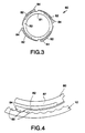
- Fig. 3 is a detailed enlarged top plan view of a component in accordance with an embodiment of the present invention; and
- Fig. 4 is a partial top plan view of the component of Fig. 3 engaging the sleeve member as in Fig. 1.
-
- Repeat use of reference characters in the present specification and drawings is intended to represent same or analogous features or elements of the invention.
- It is to be understood by one of ordinary skill in the art that the present discussion is a description of exemplary embodiments only, and is not intended as limiting the broader aspects of the present invention, which broader aspects are embodied in the exemplary construction.
- Referring to Fig. 1, a
chuck 10 in accordance with the present invention is illustrated. Chuck 10 includes afront sleeve member 12, an optionalrear sleeve member 14, abody member 16, and a plurality ofjaws 18. Referring to Figs. 1 and 2,body member 16 is generally cylindrical in shape and comprises a nose orforward section 20 and a tail orrearward section 22. As shown in Fig. 1, anaxial bore 24 is formed in thenose section 20 of thebody member 16.Axial bore 24 is somewhat larger than the largest tool shank that the chuck is designed to accommodate. A threadedbore 26 is formed intail section 22 ofbody 16 and is of a standard size to mate with the drive shaft of a powered or hand driver (not shown). While a threadedbore 26 is illustrated, such bore could be replaced with a tapered bore of a standard size to mate with a tapered drive shaft. Thebores central region 28 ofbody member 16. - A
separate passageway 30 is formed inbody member 16 to accommodate eachjaw 18. A plurality ofjaws 18 and corresponding passageways are provided. Referring to Fig. 1, when threejaws 18 are employed, eachjaw 18 is separated from the adjacent jaw by an arc of approximately 120 degrees. The longitudinal axes of thepassageways 30 and thejaws 18 are angled with respect to the longitudinal axis of the chuck but intersect the chuck axis at a common point ahead of thechuck body 16. Eachjaw 18 has atool engaging face 32, which is generally parallel to the longitudinal axis of thechuck body 16, andthreads 34 on its opposite or outer surface.Threads 34 of any suitable type and pitch may be utilized within the scope of the present invention as would be readily apparent to one skilled in the art. - As illustrated in Figs. 1 and 2,
body member 16 includes athrust ring member 36 which, in a preferred embodiment, is integral therewith and constitutes the thrust-receivingportion 36 ofbody member 16. Although not presently preferred,thrust ring member 36 may be a separate component from the body member. As shown in Fig. 1,thrust ring member 36 includes aledge portion 38, which can be adapted for engagement with the shroud or outer race of a self-contained anti-friction bearingassembly 42 as will be described in more detail below. Thrustring member 36 includes a plurality ofjaw guideways 40 formed around the circumference in alignment withpassageways 30 to permit movement (retraction and extension) of thejaws 18 throughguideways 40. - Referring to Figs. 1 and 2,
tail section 22 ofbody member 16 can include a rearcylindrical portion 44 with aknurled surface 46 thereon for receipt of optionalrear sleeve 14 to be pressed thereon if so desired. As shown in Fig. 2,body 16 further includes a firsttapered portion 48 extending from rearcylindrical portion 44 to the region ofthrust ring 36. A first centralcylindrical portion 51 extends from the region ofthrust ring 36 to a second centralcylindrical portion 52 having a diameter less than first centralcylindrical portion 51. A frontcylindrical portion 53 extends from one end of second centralcylindrical portion 52 to abeveled nose portion 56 that is adapted to receive anosepiece 58 for maintaining thefront sleeve 12 in driving engagement with a nut as will be set forth in more detail below. Alternatively, a snap ring or the like could be utilized to maintain thefront sleeve 12 in place or thefront sleeve 12 could be pressed on or otherwise secured to the nut (described below). - The present invention further includes a
nut 60 rotatably mounted with respect tobody member 16 and in engagement withthreads 34 onjaws 18. As shown in Fig. 1,nut 60 includesthreads 62 for mating withthreads 34 onjaws 18 whereby whennut 60 is rotated with respect tobody 16, thejaws 18 will be advanced or retracted in a particular direction along the longitudinal axis of thepassageways 30. This direction has a component along the longitudinal axis of thebody member 16. As shown in Fig. 2,nut 60 may include driveslots 66 for mating withdrive ribs 68 onfront sleeve 12. In thisway nut 60 is keyed tofront sleeve 12 so that whenfront sleeve 12 is rotated,nut 60 will rotate therewith and movejaws 18 as set forth above. In a preferred embodiment,nut 60 is configured in the form of a one piece nut, but could be formed in two or more pieces that could be joined together or merely concentrically disposed. - As shown in Fig. 1, a
nut retainer member 69 is configured and disposed so as to cooperate with frontcylindrical portion 53 ofbody member 16 in a manner that retainsnut 60 from moving axially towardnose section 20 ofbody member 16. As shown in Fig. 2,nut retainer 69 is generally configured with a cylindrically shaped section joined to a section shaped in a truncated conical form. - In further accordance with the present invention, a spring member is provided. As shown in Figs. 1 and 2, a
spring member 80 is configured and disposed aboutbody member 16. As shown in Figs. 2 and 3, an inner surface of anannular ring portion 83 ofspring member 80 defines a centrally disposedopening 81 that permitsspring member 80 to be disposed aboutbody member 16. As shown in Figs. 1 and 2,annular ring portion 83 of spring member is configured and disposed to rest againstledge 38 ofthrust ring 36, and the diameter of opening 81 is large enough so as not to impede movement ofjaws 18 throughguideways 40 inthrust ring 36 ofbody member 16. - As shown in Figs. 1 and 4,
spring member 80 includes at least onearm 82 resiliently biased towardfront sleeve member 12 and carrying on the free end ofarm 82 at least oneboss 84 configured to engagefront sleeve member 16. As shown in Fig. 4, a plurality ofindentations 85 are configured and disposed in an inner surface near the rear edge offront sleeve member 16 so as to engage and receive the correspondingboss 84 disposed at the free end ofarm 82 ofspring member 80. As shown in Figs. 2 and 3,spring member 80 has a plurality ofarms 82 and associatedbosses 84, four being shown symmetrically disposed circumferentially around the outer periphery ofspring member 80. - As schematically denoted by the dashed outline of
arms 84 in Fig. 3, eacharm 82 resiliently deflects radially (in a general sense) inwardly toward the center of opening 81 and radially (again in a general sense) outwardly away from opening 81. In this way,arms 82,bosses 84 andindentations 85 are configured so that a circumferential force is needed to overcome the engagement. Thus, the engagement betweenindentations 85 and corresponding receivedbosses 84 provides a restraining torque. So long as this engagement does not slip during manual movement ofnut 60 by rotation ofsleeve member 12, thenfront sleeve member 12,nut 60 andspring member 80 rotate in unison rather than relative to one another. - As
nut 60 is rotated so thatjaws 18 are increasing the forward gripping force applied to the shaft of a tool, a corresponding axial force is increasingly exerted rearwardly throughjaws 18 tonut 60. This rearward axial force is transmitted throughnut 60 tobody member 16, and particularly toledge 38 ofthrust ring 36 ofbody member 16. Moreover, as shown in Figs. 1 and 2,spring member 80 is disposed betweennut 60 and thrust-receivingportion 36 ofbody member 16. More specifically,annular ring portion 83 ofspring member 80 provides the vehicle for transmitting the axial force rearwardly fromnut 60 toledge 38 ofthrust ring 36 ofbody member 16. Accordingly, this rearward axial force results in a frictional force betweenledge 38 ofthrust ring 36 ofbody member 16 andannular ring portion 83 ofspring member 80. - This resulting frictional force between
ledge 38 ofthrust ring 36 ofbody member 16 andannular ring portion 83 ofspring member 80 is directed circumferentially in a direction opposite to the direction thatfront sleeve 12 andnut 60 are being manually rotated by the user. Accordingly, this resulting frictional force acts to restrain circumferential movement ofspring member 80 with respect to thrustring 36 ofbody member 16. Thus, when thejaws 18 are tightened around the shaft of a tool in the desired manner, the resulting frictional force prevents further rotation ofspring member 80 with respect tobody member 16. In this manner,spring member 80 becomes locked tobody member 16 and therefore becomes selectively disposed nonrotatably with respect tobody member 16. - In a conventional chuck used to secure a drill engaged in hammer drilling for example, the vibration that results from use of the tool tends to cause the nut and front sleeve member to move in the direction of least resistance and, therefore, to cause the
jaws 18 to loosen (i.e., release) their grip around the shaft of the tool. However, in accordance with the chuck of the present invention, the tension in theresilient arm 82 ofspring member 80 and the configuration ofbosses 84 in relation to the configuration ofindentations 85, can be controlled to produce a restraining torque that counteracts such release torque. Thus, beforefront sleeve 12 can rotate with respect to spring member 80 (and with respect tobody member 16 secured to springmember 80 by the aforementioned rearwardly acting axial force), the magnitude of the release torque allowed by the vibrations acting on the chuck must exceed the restraining torque that preventsspring member 80 from rotating relative tofront sleeve member 12. The desired magnitude of this restraining torque is such as to prevent such vibrations from causing front sleeve member 12 (andnut 60 keyed thereto by the interaction ofdrive slots 66 and drive ribs 68) to rotate relative tobody member 16. This ensures thatjaws 18 do not loosen their desired grip around the tool shaft during such vibration of the tool when in use for its intended purpose such as hammer drilling or any other application that involves vibrations. Upon application of a torque to thefront sleeve member 12 that exceeds the restraining torque, then thefront sleeve member 12 and thenut 60 keyed thereto will be selectively rendered rotatable with respect to thespring member 80, which will be fixed nonrotatably to thebody member 16 by means of the frictional restraining force resulting from the rearwardly applied axial thrust that pinsannular ring portion 83 ofspring member 80 against the thrust-receivingportion 36 ofbody member 16. - As noted above,
spring member 80 is rotatably disposed with respect tonut 60. This is desirably accomplished by means of a bearing assembly disposed between the nut and the spring member. In one alternative embodiment, the bearing assembly includes a surface bearing between one surface ofnut 60 and one surface ofspring member 80. As shown in Fig. 1, a forwardlydisposed surface 86 ofannular ring portion 83 ofspring member 80 is disposed to face a rearwardly facingsurface 61 ofnut 60. In the view shown in Figs. 2-4, the opposite surface ofannular ring portion 83 than the surface ofring portion 83 actually shown in these Figs., is one of the surfaces that would be disposed to bear against the rearwardly facing, i.e., lower,surface 61 ofnut 60 in this surface bearing embodiment. - Desirably, at least one friction-reducing composition would be disposed between the opposed surfaces of
nut 60 andspring member 80 disposed in this surface bearing relationship. The at least one friction-reducing composition can be deployed as a coating or layer of solid film lubricant that is applied by being sprayed on one of the bearing surfaces ofnut 60 and then cured thereon. In an alternative embodiment, the components with the surfaces may be dipped or spray tumbled. A composition suitable for the friction-reducing composition is the PERMA-SLIK® lubricant distributed by E/M Corporation of West Lafayette, Indiana. The PERMA-SLIK® lubricant can be applied to each desired surface according to the instructions provided by the manufacturer. Applicants believe that a preferred cured film thickness for each such layer of the solid film lubricant is between 0.0025 mm and 0.0125 mm (0.0001-0.0005 inches). Further details concerning solid film lubricants can be learned from WO-A-9640459. - Referring to Figs. 1 and 2, an alternative embodiment of the bearing assembly disposed between
nut 60 andspring member 80 can include a self-contained bearing assembly, generally designated by the numeral 42. As shown in Fig. 1, self-containedbearing assembly 42 includes aninner race 72, anouter race 74 and bearingelements 76 maintained therebetween. In a preferred embodiment, bearingelements 76 are ball bearings. Self-containedbearing assembly 42 may further include ashroud 78 surrounding the inner andouter races inner race 72 includes anarcuate surface 73 that is dimensioned and configured to mate with a corresponding rearwardly-facingarcuate seating surface 61 formed as part ofnut 60.Nut 60 is received for support oninner race 72 and is not in frictional contact withbody 16 as in some prior art devices. Such mating relationship assists in alignment and minimization of both axial and radial stresses when the chuck is operated, as well as minimizing or eliminating frictional contact or rubbing betweennut 60 andbody 16. Further, such a relationship assists in maintaining the nut centred during tightening so as to provide more even tightening of the chuck and reducing run-out. This arrangement also maintains optimum thread. engagement with each jaw, further increasing efficiency and reducing stress in both jaw and nut threads. In a preferred embodiment, self-containedbearing assembly 42 is an angular thrust bearing. - In a preferred embodiment as set forth above,
front sleeve member 12 is adapted to be loosely fitted overnose section 20 ofchuck 10.Multiple drive ribs 68 offront sleeve 12 engagedrive slots 66 ofnut 60 so thatfront sleeve 12 andnut 60 will be operatively connected or keyed together, i.e., whenfront sleeve 12 is rotated,nut 60 will rotate therewith. As shown in Fig. 1,front sleeve 12 may include anannular ledge portion 13 disposed aboutnose section 20 ofbody member 16. Anosepiece 58 is dimensioned and adapted to be pressed ontobeveled nose portion 56 ofnose section 20 to maintainfront sleeve 12 onchuck 10. It should be appreciated thatnosepiece 58 could also be secured tobody 16 by snap fitting, threading or the like.Nosepiece 58 is exposed when the chuck is assembled and, in one embodiment, may be coated with a non-ferrous metallic coating to prevent rust and to enhance its appearance. Examples of suitable coatings include zinc or nickel, however, it should be appreciated that any suitable coating could be utilized. -
Nosepiece 58 serves to maintainfront sleeve member 12 in position onchuck 10 and in driving engagement withnut 60. Further, while a nosepiece and driving slot arrangement is illustrated, it should be appreciated that any suitable method of operative connection between the front sleeve and the nut could be utilized within the scope of the present invention. - In addition,
nosepiece 58 serves the dual purpose of providing an aesthetically pleasing cover fornose portion 56 that will resist rust. This provides the advantage of an aesthetically pleasing appearance without the necessity to coat theentire body member 16. If desired, therear sleeve member 14 may be omitted and thefront sleeve member 12 extended to the tail end ofbody 16. This alternative is particularly feasible when a spindle lock or the like is provided on the driver or when the driver is used to tighten or loosen the jaws. - The exterior circumferential surface of the
front sleeve member 12 may be knurled or may be provided with longitudinal ribs or other protrusions to enable the operator to grip it securely. In like manner, the outer circumferential surface of therear sleeve member 14, if employed, may be knurled or ribbed if desired. The front and rear sleeves may be fabricated from a structural plastic such as polycarbonate, a filled polypropylene, for example, glass filled polypropylene, or a blend of structural plastic materials. Other composite materials such as, for example, graphite filled polymerics also would be suitable in certain environments. As will be appreciated by one skilled in the art, the materials from which the chuck of the present invention is fabricated will depend on the end use of the chuck, and the above are provided by way of example only. - It will be appreciated that
rear sleeve member 14 is fixed tobody member 16, whilefront sleeve member 12 is operatively associated withnut 60 and rotatable with respect tobody member 16. Because of the interaction betweenthreads 34 onjaws 18 andthreads 62 onnut 60, relative movement of the front and rear sleeve members, 12 and 14, causesjaws 18 to be advanced or retracted, depending upon the direction of relative movement. - While the above description is set forth with respect to a keyless chuck, it should be appreciated that the principles of the present invention are equally applicable to a keyed chuck, and such is within the scope of the present invention.
- These and other modifications and variations to the present invention may be practiced by those of ordinary skill in the art, without departing from the scope of the present invention, which is set forth in the appended claims. In addition, it should be understood that aspects of the various embodiments may be interchanged both in whole or in part. Furthermore, those of ordinary skill in the art will appreciate that the foregoing description is by way of example only, and is not intended to be limitative of the invention described in such appended claims.
Claims (21)
- A chuck (10) for use with a manual or powered driver having a rotatable drive shaft, said chuck comprising:a generally cylindrical body member (16) having a nose section (20) and a tail section (22), said tail section (22) having an axial bore (26) formed therein to mate with the drive shaft of the driver, said nose section (20) having an axial bore (24) formed therein and a plurality of angularly disposed passageways (30) formed therethrough and intersecting said axial bore (26) of said nose section (20), said body member (16) including a thrust receiving portion (36);a plurality of jaws (18), a separate one of said jaws (18) being slidably positioned in one of each of said angularly disposed passageways (30), each of said jaws (18) having a jaw face formed on one side thereof and threads formed on the opposite side thereof;a nut (60) rotatably mounted with respect to said body member (16) and in engagement with said threads on said jaws (18);a spring member (80) selectively rotatable with respect to said nut (60); anda generally cylindrical front sleeve member (12) configured and disposed in driving engagement with said nut (60) and overlying said nose section (20) of said body member (16) whereby when said front sleeve member (12) is rotated with respect to said body member (16), said jaws (18) will be moved thereby; said spring member (80) being disposed operatively between said nut (60) and thrust receiving portion (36) such that in a first condition said nut (60) and thrust receiving portion (36) are freely rotatable with respect to one another, and in a second condition said spring member (80) being adapted to resist rotation of said nut (60) with respect to said thrust receiving portion (36) up to a predetermined restraining torque, characterised in that the contact between said spring member (80) and nut (60) is friction reduced compared with the contact between said spring member (80) and thrust receiving portion (36).
- A chuck as stated in claim 1, wherein said spring member (80) is circular and includes a radially extending ring portion (83) operatively between said nut (60) and thrust receiving portion (36).
- A chuck as stated in claim 1 or claim 2, wherein said front sleeve member (12) engages said spring member (80) via at least one of a plurality of indentations (85) configured in an inner surface of said front sleeve member (12).
- A chuck as stated in claim 3, wherein said spring member (80) includes at least one arm (82) having at least one boss (84) configured to be received in at least one of said plurality of indentations (85).
- A chuck for use with a manual or powered driver as stated in claim 1 or claim 2, wherein said spring member (80) has at least one arm (82) biased toward said front sleeve member (12), said at least one arm (82) having at least one boss (84) configured to engage said front sleeve member (12).
- A chuck as stated in claim 4 or claim 5, wherein said arm extends circumferentially.
- A chuck as stated in any preceding claim, wherein said spring member (80) is rotatably disposed with respect to said nut (60) by means of a bearing disposed between said nut (60) and said spring member (80).
- A chuck as stated in claim 7, wherein said bearing (42) includes at least one friction-reducing surface disposed between said nut (60) and said spring member (80).
- A chuck as stated in claim 8, wherein said at least one friction-reducing surface is formed as a coating disposed on at least one of said spring member (80) and said nut (60).
- A chuck as stated in any of claims 7-9, wherein said bearing is a self-contained bearing assembly (42) including an inner race (72), and outer race (74), and bearing elements (76) maintained between said races.
- A chuck as stated in claim 10, wherein said bearing elements are ball bearings.
- A chuck as stated in claim 10 or claim 11, wherein said self-contained bearing assembly (42) includes a shroud (78) at least partially surrounding said inner and outer races for maintaining said bearing assembly self-contained.
- A chuck as stated in claim 12, wherein said body member (16) includes a thrust receiving portion (38) disposed adjacent said shroud (78).
- A chuck as stated in claim 13, wherein said thrust receiving portion (38) is unitary with said body member (16).
- A chuck for use with a manual or powered driver as stated in claim 13 or claim 14, wherein said thrust receiving portion (38) includes a ledge and wherein said self-contained bearing assembly (42) is received on said ledge.
- A chuck as stated in any of claims 10-15, wherein each of said nut (60) and said inner race (72) includes a corresponding arcuate seating surface (73) for mating with one another.
- A chuck as stated in any of claims 10-16, wherein said bearing assembly is an angular thrust bearing.
- A chuck as stated in any preceding claim, wherein said nut (60) is a one piece nut.
- A chuck as stated in any preceding claim, wherein said nut (60) include drive slots (66) for receipt of drive ribs (68) on said front sleeve member (12).
- A chuck as stated in any preceding claim and further including a rear sleeve member (14) secured to said tail section (22).
- A chuck as stated in any preceding claim, wherein said front sleeve member (12) is maintained on said body member (16) and in engagement with said nut (60) by a rust resistant nosepiece (58).
Applications Claiming Priority (3)
| Application Number | Priority Date | Filing Date | Title |
|---|---|---|---|
| US51451595A | 1995-08-11 | 1995-08-11 | |
| US514515 | 1995-08-11 | ||
| PCT/US1996/011456 WO1997006912A1 (en) | 1995-08-11 | 1996-07-09 | Chuck |
Publications (2)
| Publication Number | Publication Date |
|---|---|
| EP0843607A1 EP0843607A1 (en) | 1998-05-27 |
| EP0843607B1 true EP0843607B1 (en) | 2001-05-16 |
Family
ID=24047518
Family Applications (1)
| Application Number | Title | Priority Date | Filing Date |
|---|---|---|---|
| EP96923722A Expired - Lifetime EP0843607B1 (en) | 1995-08-11 | 1996-07-09 | Chuck |
Country Status (11)
| Country | Link |
|---|---|
| US (1) | US5816582A (en) |
| EP (1) | EP0843607B1 (en) |
| JP (1) | JPH11510744A (en) |
| CN (1) | CN1076235C (en) |
| AU (1) | AU6450496A (en) |
| BR (1) | BR9610243A (en) |
| CA (1) | CA2227596A1 (en) |
| DE (1) | DE69612854T2 (en) |
| MX (1) | MX9801087A (en) |
| TW (1) | TW300186B (en) |
| WO (1) | WO1997006912A1 (en) |
Families Citing this family (44)
| Publication number | Priority date | Publication date | Assignee | Title |
|---|---|---|---|---|
| US5957469A (en) * | 1996-09-25 | 1999-09-28 | Power Tool Holders, Inc. | Spring chuck |
| US5816583A (en) * | 1996-12-04 | 1998-10-06 | Power Tool Holders, Inc. | Integral locking sleeve chuck |
| WO1998040182A1 (en) * | 1997-03-12 | 1998-09-17 | Shandong Weida Machine Tool Tools Group Corporation | Manual tightened chuck |
| US6179512B1 (en) * | 1998-05-29 | 2001-01-30 | Power Tool Holders Incorporated | Collet nut |
| US6073939A (en) | 1998-06-05 | 2000-06-13 | Power Tool Holders Incorporated | Locking chuck |
| US6102411A (en) * | 1998-08-14 | 2000-08-15 | Power Tool Holders, Inc. | Chuck with locking sleeve |
| US5934690A (en) * | 1998-09-02 | 1999-08-10 | Chum Power Machinery Corp. | Chuck unit of a power hand tool |
| US6260856B1 (en) * | 1999-11-17 | 2001-07-17 | Power Tool Holders Incorporated | Locking chuck |
| US6390481B1 (en) * | 2000-03-10 | 2002-05-21 | Power Tool Holders Incorporated | Locking chuck |
| US6302407B1 (en) * | 2000-04-20 | 2001-10-16 | Chun Chu Hsueh | Chuck structure with locking and positioning functions |
| US6540237B1 (en) | 2000-06-23 | 2003-04-01 | Power Tool Holders Incorporated | Chuck |
| EP1547709A3 (en) † | 2000-07-03 | 2005-08-31 | Röhm GmbH | Drill Chuck |
| US6398226B1 (en) * | 2000-08-02 | 2002-06-04 | Power Tool Holders Incorporated | Chuck with one-way lock |
| US6502836B1 (en) * | 2000-12-06 | 2003-01-07 | Power Tool Holders Incorporated | Chuck with spring leg dust cover |
| DE10101212A1 (en) * | 2001-01-11 | 2002-07-18 | Roehm Gmbh | chuck |
| DE10106251B4 (en) * | 2001-02-10 | 2005-07-28 | Röhm Gmbh | chuck |
| CN1217762C (en) * | 2001-06-10 | 2005-09-07 | 山东威达机械股份有限公司 | Self-locking clamping chuck of drill bit |
| CN1220569C (en) * | 2001-06-10 | 2005-09-28 | 山东威达机械股份有限公司 | Self-fastening clamping chuck of drill bit |
| US6554289B1 (en) * | 2001-10-11 | 2003-04-29 | Chum Power Machinery Corp. | Anti-slip type electric drill chuck |
| US6948893B2 (en) * | 2002-12-23 | 2005-09-27 | Dr. Joerg Guehring | Clamping system coated with solid lubricant for machine tools |
| CN100404177C (en) * | 2003-07-15 | 2008-07-23 | 山东威达机械股份有限公司 | Locking type drill gripping head |
| US7451990B2 (en) | 2004-04-29 | 2008-11-18 | Jacobs Chuck Manufacturing Company | Chuck with torque indicator |
| CN2715890Y (en) * | 2004-08-03 | 2005-08-10 | 山东威达机械股份有限公司 | Self-locking drill chuck with noise |
| US7331584B2 (en) | 2004-09-17 | 2008-02-19 | Black & Decker Inc. | Chuck with nutating gear reduction |
| US7000926B1 (en) * | 2004-10-29 | 2006-02-21 | Zhe Jiang San Ou Machinery Co.Ltd | Manually tightened drill chuck |
| US7708288B2 (en) | 2005-05-18 | 2010-05-04 | Jacobs Chuck Manufacturing Company | Locking chuck |
| US7472913B2 (en) | 2005-06-09 | 2009-01-06 | Jacobs Chuck Manufacturing Company | Drill chuck |
| US7837200B2 (en) | 2005-07-01 | 2010-11-23 | Jacobs Chuck Manufacturing Company | Chuck |
| US7527273B2 (en) * | 2005-09-02 | 2009-05-05 | Jacobs Chuck Manufacturing Company | Locking chuck |
| US20070126188A1 (en) * | 2005-10-11 | 2007-06-07 | Daniel Puzio | Pto chuck spacer |
| FR2897789B1 (en) | 2006-02-27 | 2008-05-09 | Amyot Sa Sa Ets | TOOL HOLDER CHUCK FOR THE EQUIPMENT OF A ROTATING MACHINE WITH RADIAL LOCKING AND AXIAL SEQUENCE MECHANISMS |
| US7845651B2 (en) * | 2006-08-15 | 2010-12-07 | Jacobs Chuck Manufacturing Company | Locking chuck |
| CN100579696C (en) * | 2007-01-26 | 2010-01-13 | 胡振钱 | Drill chuck with further locking function |
| US7900937B2 (en) * | 2007-08-17 | 2011-03-08 | Jacobs Chuck Manufacturing Company | Locking chuck |
| US8403339B2 (en) * | 2008-06-18 | 2013-03-26 | Jacobs Chuck Manufacturing Company | Self tightening chuck with an axial lock |
| US8376371B2 (en) * | 2008-09-17 | 2013-02-19 | Jacobs Chuck Manufacturing Company | Locking chuck jaws |
| DE202009005187U1 (en) * | 2008-11-24 | 2009-10-29 | Zhejiang Sanou Machinery Co. Ltd., Taizhou | Keyless drill chuck with self-locking |
| US8777232B2 (en) | 2009-07-29 | 2014-07-15 | Jacobs Chuck Manufacturing Company | Self-tightening chuck with a radial lock |
| CN103252513B (en) * | 2012-02-17 | 2015-10-28 | 山东威达机械股份有限公司 | Cartridge device |
| DE202012102742U1 (en) * | 2012-07-23 | 2013-04-25 | Röhm Gmbh | chuck |
| CN202779945U (en) | 2012-08-01 | 2013-03-13 | 山东威达机械股份有限公司 | Drill chuck |
| JP2015231649A (en) * | 2014-06-10 | 2015-12-24 | 株式会社 ムラテクノロジー | Chuck device |
| WO2018068284A1 (en) * | 2016-10-14 | 2018-04-19 | Jacobs Chuck Manufacturing (Suzhou) Company, Ltd. | Chuck with slip protection |
| US11511354B2 (en) | 2017-07-28 | 2022-11-29 | Apex Brands, Inc. | Locking chuck with anti-vibration feature |
Family Cites Families (15)
| Publication number | Priority date | Publication date | Assignee | Title |
|---|---|---|---|---|
| US573189A (en) * | 1896-12-15 | Ernest ii | ||
| US5234223A (en) * | 1987-07-21 | 1993-08-10 | Sakamaki Mfg. Co., Ltd. | Chuck for tools |
| US5125673A (en) * | 1989-12-11 | 1992-06-30 | Huff Robert O | Non-impact keyless chuck |
| JPH05180301A (en) * | 1991-04-08 | 1993-07-20 | Delta:Kk | Torque limiter for reduction gear mechanism |
| JPH0783961B2 (en) * | 1991-06-13 | 1995-09-13 | ユキワ精工株式会社 | Tool chuck |
| JPH05301107A (en) * | 1991-11-11 | 1993-11-16 | Jacobs Japan Inc | Tool chuck |
| DE4238503C1 (en) * | 1992-11-14 | 1993-11-25 | Roehm Guenter H | Drill chuck |
| BR9304703A (en) * | 1992-11-14 | 1994-05-17 | Roehm Guenter H | Drill chuck |
| FR2702975B1 (en) * | 1993-03-26 | 1995-06-16 | Amyot Ets Sa | TOOL HOLDER CHUCK FOR THE EQUIPMENT OF A ROTATING MACHINE, SUCH AS A DRILL. |
| US5348317A (en) * | 1993-08-13 | 1994-09-20 | Jacobs Chuck Technology Corporation | Chuck |
| US5348318A (en) * | 1993-08-13 | 1994-09-20 | Jacobs Chuck Technology Corporation | Chuck |
| DE4407854B4 (en) * | 1994-03-09 | 2008-03-27 | Röhm Gmbh | chuck |
| DE4416224C1 (en) * | 1994-05-07 | 1995-11-23 | Metabowerke Kg | Keyless chuck |
| TW342756U (en) * | 1994-08-31 | 1998-10-11 | Yukiwa Seiko Kk | Chuck apparatus |
| DE4438991C5 (en) * | 1994-10-31 | 2009-07-30 | Röhm Gmbh | chuck |
-
1996
- 1996-07-09 BR BR9610243A patent/BR9610243A/en not_active Application Discontinuation
- 1996-07-09 DE DE69612854T patent/DE69612854T2/en not_active Expired - Lifetime
- 1996-07-09 CN CN96196320A patent/CN1076235C/en not_active Expired - Fee Related
- 1996-07-09 MX MX9801087A patent/MX9801087A/en unknown
- 1996-07-09 JP JP9509271A patent/JPH11510744A/en not_active Ceased
- 1996-07-09 EP EP96923722A patent/EP0843607B1/en not_active Expired - Lifetime
- 1996-07-09 WO PCT/US1996/011456 patent/WO1997006912A1/en active IP Right Grant
- 1996-07-09 CA CA002227596A patent/CA2227596A1/en not_active Abandoned
- 1996-07-09 AU AU64504/96A patent/AU6450496A/en not_active Abandoned
- 1996-08-28 TW TW085110440A patent/TW300186B/zh active
- 1996-12-06 US US08/755,848 patent/US5816582A/en not_active Expired - Lifetime
Also Published As
| Publication number | Publication date |
|---|---|
| CN1076235C (en) | 2001-12-19 |
| JPH11510744A (en) | 1999-09-21 |
| DE69612854D1 (en) | 2001-06-21 |
| AU6450496A (en) | 1997-03-12 |
| BR9610243A (en) | 1999-06-15 |
| DE69612854T2 (en) | 2001-08-30 |
| TW300186B (en) | 1997-03-11 |
| MX9801087A (en) | 1998-04-30 |
| CA2227596A1 (en) | 1997-02-27 |
| US5816582A (en) | 1998-10-06 |
| WO1997006912A1 (en) | 1997-02-27 |
| CN1193294A (en) | 1998-09-16 |
| EP0843607A1 (en) | 1998-05-27 |
Similar Documents
| Publication | Publication Date | Title |
|---|---|---|
| EP0843607B1 (en) | Chuck | |
| EP0932466B2 (en) | Chuck | |
| EP0713432B1 (en) | Chuck | |
| US5957469A (en) | Spring chuck | |
| EP0775033B1 (en) | Chuck | |
| EP0818262B1 (en) | Chuck | |
| US7128324B2 (en) | Hammerlock chuck | |
| MXPA98001087A (en) | Device for attaching trab tools | |
| US6017039A (en) | Nosepiece nut retainer chuck | |
| US5829762A (en) | Chuck with locking unit |
Legal Events
| Date | Code | Title | Description |
|---|---|---|---|
| PUAI | Public reference made under article 153(3) epc to a published international application that has entered the european phase |
Free format text: ORIGINAL CODE: 0009012 |
|
| 17P | Request for examination filed |
Effective date: 19980213 |
|
| AK | Designated contracting states |
Kind code of ref document: A1 Designated state(s): CH DE FR GB IT LI NL |
|
| 17Q | First examination report despatched |
Effective date: 19980622 |
|
| GRAG | Despatch of communication of intention to grant |
Free format text: ORIGINAL CODE: EPIDOS AGRA |
|
| GRAG | Despatch of communication of intention to grant |
Free format text: ORIGINAL CODE: EPIDOS AGRA |
|
| GRAH | Despatch of communication of intention to grant a patent |
Free format text: ORIGINAL CODE: EPIDOS IGRA |
|
| GRAH | Despatch of communication of intention to grant a patent |
Free format text: ORIGINAL CODE: EPIDOS IGRA |
|
| GRAA | (expected) grant |
Free format text: ORIGINAL CODE: 0009210 |
|
| AK | Designated contracting states |
Kind code of ref document: B1 Designated state(s): CH DE FR GB IT LI NL |
|
| PG25 | Lapsed in a contracting state [announced via postgrant information from national office to epo] |
Ref country code: NL Free format text: LAPSE BECAUSE OF FAILURE TO SUBMIT A TRANSLATION OF THE DESCRIPTION OR TO PAY THE FEE WITHIN THE PRESCRIBED TIME-LIMIT Effective date: 20010516 Ref country code: IT Free format text: LAPSE BECAUSE OF FAILURE TO SUBMIT A TRANSLATION OF THE DESCRIPTION OR TO PAY THE FEE WITHIN THE PRESCRIBED TIME-LIMIT;WARNING: LAPSES OF ITALIAN PATENTS WITH EFFECTIVE DATE BEFORE 2007 MAY HAVE OCCURRED AT ANY TIME BEFORE 2007. THE CORRECT EFFECTIVE DATE MAY BE DIFFERENT FROM THE ONE RECORDED. Effective date: 20010516 Ref country code: FR Free format text: LAPSE BECAUSE OF FAILURE TO SUBMIT A TRANSLATION OF THE DESCRIPTION OR TO PAY THE FEE WITHIN THE PRESCRIBED TIME-LIMIT Effective date: 20010516 |
|
| REG | Reference to a national code |
Ref country code: CH Ref legal event code: EP |
|
| REF | Corresponds to: |
Ref document number: 69612854 Country of ref document: DE Date of ref document: 20010621 |
|
| REG | Reference to a national code |
Ref country code: CH Ref legal event code: NV Representative=s name: AMMANN PATENTANWAELTE AG BERN |
|
| NLV1 | Nl: lapsed or annulled due to failure to fulfill the requirements of art. 29p and 29m of the patents act | ||
| EN | Fr: translation not filed | ||
| REG | Reference to a national code |
Ref country code: GB Ref legal event code: IF02 |
|
| PLBE | No opposition filed within time limit |
Free format text: ORIGINAL CODE: 0009261 |
|
| STAA | Information on the status of an ep patent application or granted ep patent |
Free format text: STATUS: NO OPPOSITION FILED WITHIN TIME LIMIT |
|
| RAP2 | Party data changed (patent owner data changed or rights of a patent transferred) |
Owner name: POWER TOOL HOLDERS, INC. |
|
| 26N | No opposition filed | ||
| REG | Reference to a national code |
Ref country code: CH Ref legal event code: PFA Free format text: POWER TOOL HOLDERS INCORPORATED,SUITE 105, 501 SILVERSIDE ROAD,WILMINGTON, DE 19809 (US) TRANSFER- POWER TOOL HOLDERS, INC.,16 WEST MAIN STREET,CHRISTIANA, DE 19702 (US) |
|
| PGFP | Annual fee paid to national office [announced via postgrant information from national office to epo] |
Ref country code: CH Payment date: 20020910 Year of fee payment: 7 |
|
| PG25 | Lapsed in a contracting state [announced via postgrant information from national office to epo] |
Ref country code: LI Free format text: LAPSE BECAUSE OF NON-PAYMENT OF DUE FEES Effective date: 20030731 Ref country code: CH Free format text: LAPSE BECAUSE OF NON-PAYMENT OF DUE FEES Effective date: 20030731 |
|
| REG | Reference to a national code |
Ref country code: CH Ref legal event code: PL |
|
| REG | Reference to a national code |
Ref country code: GB Ref legal event code: 732E Free format text: REGISTERED BETWEEN 20140612 AND 20140618 |
|
| REG | Reference to a national code |
Ref country code: DE Ref legal event code: R082 Ref document number: 69612854 Country of ref document: DE Representative=s name: CANZLER & BERGMEIER PATENTANWAELTE, DE |
|
| PGFP | Annual fee paid to national office [announced via postgrant information from national office to epo] |
Ref country code: GB Payment date: 20140624 Year of fee payment: 19 |
|
| REG | Reference to a national code |
Ref country code: DE Ref legal event code: R082 Ref document number: 69612854 Country of ref document: DE Representative=s name: CANZLER & BERGMEIER PATENTANWAELTE, DE Effective date: 20140725 Ref country code: DE Ref legal event code: R081 Ref document number: 69612854 Country of ref document: DE Owner name: APEX BRANDS, INC. (N.D.GES.D. STAATES DELAWARE, US Free format text: FORMER OWNER: POWER TOOL HOLDERS INC., WILMINGTON, DEL., US Effective date: 20140725 |
|
| PGFP | Annual fee paid to national office [announced via postgrant information from national office to epo] |
Ref country code: DE Payment date: 20140630 Year of fee payment: 19 |
|
| REG | Reference to a national code |
Ref country code: DE Ref legal event code: R119 Ref document number: 69612854 Country of ref document: DE |
|
| GBPC | Gb: european patent ceased through non-payment of renewal fee |
Effective date: 20150709 |
|
| PG25 | Lapsed in a contracting state [announced via postgrant information from national office to epo] |
Ref country code: DE Free format text: LAPSE BECAUSE OF NON-PAYMENT OF DUE FEES Effective date: 20160202 Ref country code: GB Free format text: LAPSE BECAUSE OF NON-PAYMENT OF DUE FEES Effective date: 20150709 |