EP0843308B1 - Disk changer device - Google Patents
Disk changer device Download PDFInfo
- Publication number
- EP0843308B1 EP0843308B1 EP97309125A EP97309125A EP0843308B1 EP 0843308 B1 EP0843308 B1 EP 0843308B1 EP 97309125 A EP97309125 A EP 97309125A EP 97309125 A EP97309125 A EP 97309125A EP 0843308 B1 EP0843308 B1 EP 0843308B1
- Authority
- EP
- European Patent Office
- Prior art keywords
- disk
- transporting
- holding member
- gear
- chucking
- Prior art date
- Legal status (The legal status is an assumption and is not a legal conclusion. Google has not performed a legal analysis and makes no representation as to the accuracy of the status listed.)
- Expired - Lifetime
Links
- 230000007246 mechanism Effects 0.000 claims description 73
- 238000003780 insertion Methods 0.000 claims description 7
- 230000037431 insertion Effects 0.000 claims description 7
- 230000032258 transport Effects 0.000 claims description 4
- 230000001360 synchronised effect Effects 0.000 claims description 2
- 239000007858 starting material Substances 0.000 description 39
- 238000010276 construction Methods 0.000 description 26
- 238000010586 diagram Methods 0.000 description 20
- 230000002829 reductive effect Effects 0.000 description 9
- 230000000694 effects Effects 0.000 description 6
- 230000002441 reversible effect Effects 0.000 description 5
- 230000001965 increasing effect Effects 0.000 description 4
- 230000003028 elevating effect Effects 0.000 description 3
- 238000000034 method Methods 0.000 description 3
- 239000000284 extract Substances 0.000 description 2
- 230000008569 process Effects 0.000 description 2
- 230000035939 shock Effects 0.000 description 2
- 230000008859 change Effects 0.000 description 1
- 230000001747 exhibiting effect Effects 0.000 description 1
- 230000002401 inhibitory effect Effects 0.000 description 1
- 230000000977 initiatory effect Effects 0.000 description 1
- 230000000717 retained effect Effects 0.000 description 1
- 230000005068 transpiration Effects 0.000 description 1
Images










Classifications
-
- G—PHYSICS
- G11—INFORMATION STORAGE
- G11B—INFORMATION STORAGE BASED ON RELATIVE MOVEMENT BETWEEN RECORD CARRIER AND TRANSDUCER
- G11B17/00—Guiding record carriers not specifically of filamentary or web form, or of supports therefor
- G11B17/22—Guiding record carriers not specifically of filamentary or web form, or of supports therefor from random access magazine of disc records
- G11B17/221—Guiding record carriers not specifically of filamentary or web form, or of supports therefor from random access magazine of disc records with movable magazine
- G11B17/223—Guiding record carriers not specifically of filamentary or web form, or of supports therefor from random access magazine of disc records with movable magazine in a vertical direction
Definitions
- the present invention relates to a disk changer device which is mounted with a magazine storing a plurality of disk holding members which hold disks and which extracts disks from this magazine and performs recording / replay of these disks, and particularly relates to a loading mechanism for performing the operation of extracting disk holding members from the magazine, the operation of chucking the disks, and the operation of returning the empty disk holding members to the magazine.
- disk devices such as CD players wherein a magazine capable of storing a plurality of disks is provided thereto and automatic selection of one of the plurality of disks stored within the magazine is selected according to selection made by the user so that recording / replay thereof can be made, in order to reduce disk exchanging operations by the user as much as possible, thereby increasing ease of use.
- a disk changer device is provided for selectively extracting the desired disk from the magazine mounted to the magazine mounting portion and transporting this disk to the recording / replay means, and returning the disk to the magazine again following recording / replay thereof, in order to perform sequential recording / replay of a plurality of disks by means of common recording / replay means which conducts recording / replay of the disks.
- a disk changer device differs according to the configuration of the magazine to be used.
- a disk changer device is disclosed in Japanese Unexamined Patent Publication 6-290528 employing a magazine provided with disk holding members which can easily hold disks simply by inserting the disks in the plate surface direction thereof.
- Fig. 28 is a drawing illustrating this device disclosed in the Publication.
- This disk changer device illustrated in Fig. 28 is provided with a recording / replay unit 2 capable of moving vertically as to a chassis 1, and a transporting / chucking mechanism 3.
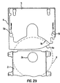
- the magazine 4 is constructed such that a plurality of disk holding members 5 such as shown in Fig. 29 are arrayed so as to be extractable therefrom and replaceable thereto.
- the disk holding member 5 is formed in a cylindrical shape which can store only one disk 6, and is provided with disk insertion opening 5a situated on the side of the opening 4a of the magazine 4, and with a spring 5b provided internally. At the point that the disk 6 is inserted to the predetermined position from the insertion opening 5a, the disk 6 is held by the spring 5b.
- This disk holding member 5 is also configured so as to be extracted to the position above a turntable 2a of the recording / replay unit 2 by means of a transporting member 3a of the transporting / chucking mechanism 3, as shown in Fig. 28.
- a cam gear 7 provided with two gullet portions 7a, two cam grooves 7b and 7c, and an arm linkage 7d is used as a single driving source, as shown in Fig. 30, and the arrangement is such that the transporting / chucking mechanism 3 is driven by means of the rotation of this cam gear 7.
- Fig. 30 a cam gear 7 provided with two gullet portions 7a, two cam grooves 7b and 7c, and an arm linkage 7d
- the arm linkage 7d on the periphery of the cam gear 7 is linked to one end of the arm 3b of the transporting / chucking mechanism 3, with the other end of this arm 3b being linked to the transporting member 3a via a gear mechanism 3f comprised of a large and small gear 3c, fixed rack 3d, and a rack 3e provided to the transporting member 3a, and so forth.
- the arrangement of the gear mechanism 3f is such that the motion stroke of the arm linkage 7d in the transportation direction is doubled and transferred to the transporting member 3a.
- the two cam grooves 7b and 7c of the cam gear 7 are arranged so as to drive an unshown chucking unit.
- the recording / replay unit 2 and transporting / chucking mechanism 3 are vertically moved, and positioned at a position corresponding with one of the disk holding members 5 of the magazine 4, and then the following disk loading operation is performed by means of the cam gear 7 turning on the first direction by 360 . That is to say, in the disk loading operation, first, the transporting member 3a is driven by means of the cam gear 7 rotating in the first direction by 180 so as to extract the disk holding member 5 holding the disk 6 from the magazine 4.
- the chucking unit is driven by the gullet portion 7a of the cam gear 7 so as to perform chucking of the disk 6 on the turntable 2a.
- the transporting member 3a is driven by means of the cam gear 7 rotating in the first direction by 180 so as to cause the disk holding member 5 to move in the direction opposite to the extracting direction (i.e., the returning direction), thereby returning the disk holding member 5 to within the magazine 4. Consequently, the disk 6 chucked onto the turntable 2a is extracted from the disk holding member 5 during this moving of the disk holding member 5 and left on the turntable 2a, so the disk holding member 5 alone is returned into the magazine 4.
- the transporting member 3a is driven by means of the cam gear 7 rotating in the second direction by 180 so as to extract the empty disk holding member 5 from the magazine 4, thus inserting the disk 6 which has been chucked on the turntable 2a into the holding member 5 in accordance with the movement of the holding member 5, thereby the disk 6 being held within the holding member 5.
- the chucking unit is driven by the gullet portion 7a of the cam gear 7 so as to disengage chucking of the disk 6.
- the transporting member 3a is driven by means of the cam gear 7 rotating in the second direction by 180 so as to return the disk holding member 5 to the magazine 4.
- the disk 6 is not extracted from the holding member 5, so the disk holding member 5 is returned into the magazine 4 with the disk 6 therein.
- the recording /replay unit 2 and transporting / chucking mechanism 3 are vertically moved, and positioned at positions corresponding with each of the disk holding members 5 of the magazine 4, thereby allowing the disks 6 to be extracted from the magazine 4 in a horizontal manner and chucked onto the turntable 2a of the recording / replay unit 2 in that same state. Consequently, the complicated disk transportation operation of extracting the disk from the disk holding member and lowering the disk to the turntable becomes unnecessary, and there is no need to form a gap between this disk holding member and the disk for returning the disk holding member to the magazine.
- this arrangement is advantageous in that the amount of space necessary for transporting disks can be reduced, and the number of parts can be reduced.
- the diameter of the disk is approximately 120 mm and the diameter of the chucking area at the center of the disk is approximately 40 mm, so even in the event that playing is performed in a state wherein the disk extracted from the magazine and chucked is partially overlapping the disks stored in the magazine, the disk must be extracted from the magazine by at least approximately 80 mm.
- the cam gear 7 is arranged such as to return the disk holding member 5 into the magazine 4 with the remaining half-rotation. Accordingly, the transporting member 3a needs to be moved 80 mm or more with the half rotation of the cam gear 7. Conversely, as described above, the motion stroke in the transporting direction of the arm linkage 7d at the periphery of the cam gear 7 is doubled by the gear mechanism 3f and transferred to the transporting member 3a, but even in this case, the cam gear 7 needs to have a diameter of at least 40 mm or more. Accordingly, a large-diameter cam gear 7 needs to be provided in the vertical direction, thus increasing the height-wise dimensions.
- the transporting direction of the disk holding member cannot be immediately determined from the direction of rotation of the cam gear 7 alone, so data regarding both the direction of rotation of the cam gear 7 and the amount of rotation from the predetermined position is required for making determination. Consequently, in the event that the user desires to change the operation which is presently begin performed, there is the possibility that appropriate and speed control may not be able to be conducted. Specifically, in the event that the power goes of or so forth during an operation, the data regarding the contents of operations performed so far is lost, and in such a case, the operation being performed before power outage cannot be resumed due to the necessity of returning the mechanism to the initial state and then initiating operations, etc., and continuity of control cannot be maintained.
- the present invention has been made in order to solve the above-described problems of the conventional art, and it is an object thereof to provide a disk changer device which is capable of maintaining continuity of control, small, and simple, by means of perpetually maintaining a 1-to-1 correspondence relation between the direction of rotation of the driving source and the direction of operation of the disk holding member.
- the present invention extracts the disk from the magazine and performs chucking to the recording / replay means, and also improves the construction of the driving means for driving the disk holding member transporting means and chucking means in the loading mechanism for returning the chucked disk to the magazine, thereby providing a 1-to-1 correspondence relation between the direction of rotation of the driving source and the direction of operation of the disk holding member.
- the present invention first comprises recording / replay means for performing either or both of recording to and playing from a disk.
- the present invention also comprises chucking means for chucking a disk to the aforementioned recording / replay means, and disk holding member transporting means for extracting disk holding members from a magazine in which a plurality of the aforementioned disk holding members each for holding disks by means of insertion of the aforementioned disks in the plate surface direction thereof are stored in an array so as to be extractable from and replaceable to the magazine, and transporting the aforementioned disk holding members to a certain transporting position within the device.
- the present invention comprises moving means for supporting the aforementioned recording / replay means, chucking means, and disk holding member transporting means, and allowing these to be movable in the direction of array of the disk holding members within the aforementioned magazine in order to do away with vertical transportation of the disk.
- the present invention comprises driving means for driving the aforementioned disk holding member transporting means and chucking means so as to extract the aforementioned disk holding member transporting means holding a disk from the aforementioned magazine, chucking the disk held by the aforementioned disk holding member to the aforementioned recording / replay means, and subsequently returning the aforementioned disk holding member alone to the aforementioned magazine.
- the driving means comprises a single driving source and a selecting mechanism for separately and selectively transferring the output of the driving source to the aforementioned disk holding member transporting means and chucking means.
- the recording / replay means, chucking means, and disk holding member transporting means are moved all at once, positioned with the disk holding member holding the disk within the magazine which is to be played, and then the output of the driving source is selectively transmitted to the disk holding member transporting means and chucking means via the selecting mechanism, whereby the following disk loading operation is performed. i.e., in the disk loading operation, the output of the driving source is transferred via the selecting mechanism to the disk holding member transporting means, chucking means, and disk holding member transporting means in that order, thereby extracting the disk holding member from the magazine, and following the disk being chucked to the recording / replay means, the disk holding member is returned to the magazine.
- the output of the driving source is transferred via the selecting mechanism to the disk holding member transporting means, chucking means, and disk holding member transporting means in that order, thereby extracting the disk holding member from the magazine, and following the disk being chucked to the recording / replay means, the disk holding member is returned to the magazine.
- the output of the single driving source is not directly transferred to the disk holding member transporting means and chucking means, but a selecting mechanism is provided between both means, so that directional independence of both means can be secured, as compared to cases wherein both means are directly driven by using a single driving source such as a cam gear or the like.
- a single driving source such as a cam gear or the like.
- the disk holding member transporting means and chucking means can be driven separately and selectively including the corresponding relation of the directionality with the driving source according to the construction of the selecting mechanism, and accordingly, there is no limitation die to the operation of the chucking means, and a 1-to-1 correspondence relation can easily be maintained between the direction of rotation of the,driving source and the direction of operation of the disk holding member.
- such a selecting mechanism can be easily realized with a small and simple construction using various gears such as gears or cam gears having gullets, planetary gears, etc.
- the invention according to Claim 1 has the driving means and chucking means thereof constructed as follows. i.e., the driving means is constructed so as to rotate in a certain direction, and the chucking means is constructed so as to continuously perform chucking operation and chucking disengaging operation, based on the rotation in the certain direction of the driving source.
- the chucking means performs chucking operations and chucking disengaging operations, which are entirely opposite operations.
- the chucking means has to perform chucking operation or chucking disengaging operation each time the driving source is reversed in the direction of rotation thereof, making it difficult to maintain a directional corresponding relation between the driving source and the disk holding member transporting means.
- the arrangement is such that chucking operation and chucking disengaging operation is performed continuously regarding rotation of the driving source in a certain direction, so that chucking operation or chucking disengaging operation can be performed in a sure manner at a position appropriately matched with the operation of the disk holding member, simply by appropriately setting the relation between the amount of rotation of the driving source necessary for operation of the disk holding member transporting means, and the amount of rotation of the driving source between the chucking operation and chucking disengaging operation.
- the invention according to Claim 1 or Claim 2 has the driving means and disk holding member transporting means thereof constructed as follows. i.e., the driving means thereof is constructed so as to perform rotation in two directions, and the aforementioned disk holding member transporting means being constructed so as to extract the aforementioned disk holding members from the aforementioned magazine based on rotation of the aforementioned driving source in one direction, and to return the aforementioned disk holding members to the aforementioned magazine based on rotation of the aforementioned driving source in the other direction.
- the disk holding member transporting means only needs to perform the same reciprocal operation for both disk loading operation and disk ejecting operation, of transporting the disk holding member in the direction of extracting, and then transporting in the reverse direction (return direction).
- the direction of operation of the disk holding member transporting means and the direction of rotation of the driving source are corresponded, so that in both cases of disk loading operation and disk ejecting operation, the operation direction of the disk holding member can be easily switched simply by switching the rotation direction of the driving source, and even in the event that the power is turned off, the operation being performed before power outage can be resumed.
- the selecting mechanism is provided with functions to transfer the directionality of the output of the driving source to the disk holding member transporting means as is, and to disengage the driving source with the disk holding member transporting means when performing chucking or disengaging.
- Such functions can be easily realized with a small and simple construction using gears having gullets, etc.
- only the directional corresponding relation between the driving source and the disk holding member transporting means needs to be taken into consideration, with no restriction whatsoever from the chucking operations, thus further reducing the size and complexity of the selecting mechanism.
- the invention according to any of the Claims 1 through 3 has the selecting mechanism thereof comprised of an output gear, transporting driving rack, gullet, planetary gear, chucking driving gear, and cam.
- the output gear is constructed so as to rotate in a direction corresponding with the rotation of the aforementioned driving source.
- the transporting driving rack is provided to the aforementioned disk holding member transporting means and is linked with the aforementioned output gear so as to move the aforementioned disk holding member transporting means by the rotation of the aforementioned output gear.
- the gullet portion is provided to the linkage portion between the aforementioned output gear and the aforementioned transporting driving rack and is constructed so as to disengage the linkage between the output gear and transporting driving rack in the event that the disk holding member transporting means completes transporting of the aforementioned disk holding member to the aforementioned certain transporting position.
- the planetary gear is linked with the aforementioned output gear, and is provided so as to rotate around the periphery of the aforementioned output gear.
- the chucking driving gear is provided so as to be able to be linked with the aforementioned planetary gear according to the rotational position of the planetary gear, and is constructed so as to drive the aforementioned chucking means by means of the rotation of the aforementioned planetary gear when linked with the planetary gear.
- the cam is provided so as to move according to the position of the aforementioned disk holding member transporting means.
- This can is constructed so as to restrict the rotation of the aforementioned planetary gear while the aforementioned disk holding member transporting means transports the aforementioned disk holding member to the aforementioned certain transporting position, and which allows rotation of the aforementioned planetary gear in the direction of linkage with the aforementioned chucking driving gear in the event that the aforementioned disk holding member transporting means completes transporting of the aforementioned disk holding member to the certain transporting position.
- the output from the output gear is transferred via the transporting driving rack and the linkage with the output gear is disengaged by means of the gullet
- the output from the output gear is transferred via the planetary gear and chucking driving gear and the linkage with the output gear is disengaged by means of the cam which restricts rotation of the planetary gear.
- the disk holding member transporting means moves in the extracting direction by means of the rotation of the output gear linked via the transporting driving rack, and at the point that the disk holding member reaches the predetermined transporting position, disengagement with the output gear is conducted by means of the gullet portion.
- the rotation of the planetary gear is restricted by means of the cam during operation of the disk holding member transporting means, so the chucking means chucks the disk to the recording / replay means by means of the rotation of the output gear.
- the disk holding member transporting means is lined to the output gear once more via the transporting driving rack, the disk holding member transporting means is moved in the direction opposite to the extracting direction (return direction) by means of the rotation of this output gear, thereby returning the empty disk holding member to the magazine. Also, the same operation is conducted for the disk ejecting operation as with the disk loading operation, except that chucking disengaging operation is performed instead of chucking operation.
- transfer and disengagement of power to the disk holding member transporting means and chucking means can be realized in a sure manner with a small and simple construction comprised of an output gear, transporting driving rack, gullet, planetary gear, chucking driving gear, and cam.
- the invention according to Claims 5 has the output gear and planetary gear comprised as follows. i.e., the output gear is constructed so as to directly mesh with the aforementioned transporting driving rack and also to directly mesh with the aforementioned planetary gear, and wherein the planetary gear is provided so as to rotate around the periphery of the output gear.
- the invention according to any of the Claims 1 through 3 has the selecting mechanism thereof comprised of an output gear, planetary gear, transporting driving rack, chucking driving gear, and cam, as described below.
- the output gear is configured so as to rotate in a direction corresponding with the rotation of the aforementioned driving source.
- the planetary gear is linked with the aforementioned output gear, and is provided so as to rotate around the periphery of the aforementioned output gear between first and second rotating positions.
- the transporting driving rack is provided to the aforementioned disk holding member transporting means and is linked with the aforementioned planetary gear in the event that the planetary gear is at the aforementioned first rotational position so as to move the aforementioned disk holding member transporting means by the rotation of the planetary gear.
- the chucking driving gear is provided so as to be able to be linked with the aforementioned planetary gear in the event that the planetary gear is at the aforementioned second rotational position, and drive the aforementioned chucking means by means of the rotation of the aforementioned planetary gear when linked with the planetary gear.
- the cam is provided so as to move according to the position of the aforementioned disk holding member transporting means.
- the cam retains the aforementioned planetary gear at the aforementioned first rotational position while the aforementioned disk holding member transporting means transports the aforementioned disk holding member to the aforementioned certain transporting position, and which allows rotation of the planetary gear to the aforementioned second rotational position in the event that the disk holding member transporting means completes transporting of the aforementioned disk holding member to the certain transporting position.
- output from the output gear can be selectively transferred to the disk holding member transporting means and chucking means, via the planetary gear.
- the planetary gear is held at the first rotational position by means of control by the cam and is linked with the transporting driving rack, thereby transferring the output from the output gear to the disk holding member transporting means, and at the point that the disk holding member has been transported to the predetermined transporting position, the planetary gear is released so as to rotate to the second rotational position and is linked with the chucking driving gear, thereby transferring the output from the output gear to the chucking means.
- the disk holding member transporting means is moved in the extracting direction by means of the rotation of the output gear which is linked via the transporting driving rack and the planetary gear which is at the first rotational position, and the disk holding member is transported to the certain transporting position.
- the planetary gear is held at the first rotational position by means of control by the cam during transportation of the disk holding member, and is linked with the transporting driving rack, and on the other hand is disengaged from the chucking driving gear.
- the planetary gear is released so as to rotate to the second rotational position and is linked with the chucking driving gear, thereby linking the chucking means to the output gear, whereby the chucking means performs chucking of the disk to the recording / replay means by means of the rotation of the output gear.
- the planetary gear is retained at the first rotational position once more, thereby linking the disk holding member transporting means to the output gear via the transporting driving rack and the planetary gear, and moving the disk holding member transporting means in the direction reverse to the extracting direction (return direction) by means of the rotation of this output gear, thus returning the empty disk holding member to the magazine.
- the same operation is conducted for the disk ejecting operation as with the disk loading operation, except that chucking disengaging operation is performed instead of chucking operation.
- selective switching of transfer of output to the disk holding member transporting means and chucking means can be realized with a small and simple construction comprised of an output gear, planetary gear, transporting driving rack, chucking driving gear, and cam.
- the invention according to Claim 6 has the planetary gear thereof configured as follows. i.e., the planetary gear is provided so as to directly mesh with the output gear and is provided so as to rotate around the periphery thereof.
- a locking member is provided between the aforementioned cam and the aforementioned planetary gear, and is rotatably configured between a locking position which locks the planetary gear at the aforementioned first rotational position, and a disengaging position which disengages the lock on the planetary gear and allows rotation of the planetary gear to the aforementioned second rotational position, the motion of the locking mechanism being synchronous with the cam.
- the invention according to any of the Claims 1 through 8 has the magazine thereof detachably provided to the disk changer device.
- the magazine is detachably provided to the disk changer device so that exchange of the disks can be easily conducted by removing the magazine from the device.
- Fig. 1 is a plan view illustrating a schematic construction of a disk changer.device applied to a first embodiment of the present invention.
- Fig. 2 is an internal plan view illustrating the schematic construction of the magazine 10 used in the disk changer device shown in Fig. 1.
- FIG. 3 (A) is a plan view illustrating the schematic construction of the mounting portion of the magazine 10 shown in Fig. 2 and base unit 20, and (B) is a plan view illustrating the positional relation between the magazine lock plate 30 shown in (A) and the shift plate 25 shown in Fig. 1.
- Fig. 4 (A) is a side view illustrating the elevating construction of the loading unit 40 by means of the shift plate 25 shown in Fig. 1, and (B) is a side view illustrating the elevating construction of the loading unit 40 by means of the shift plate 26 shown in Fig. 1.
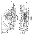
- Fig. 5 is a diagram illustrating the principal components of the loading unit 40 shown in Fig. 1, with (A) being a plan view and (B) being a side view.
- Fig. 6 is a diagram illustrating the configuration of the driving block 45 shown in Fig. 5, with (A) being a plan view and (B) being a side view.
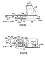
- Fig. 7 is a diagram illustrating the positional relation between the loading gear 54 shown in Fig. 5, the control plate 55, and the motor bracket 46, wherein (A) is a plan view, and (B) is a side view.
- Fig. 8 is a diagram illustrating the positional relation between the swing plate 51 shown in Fig. 5 and the transporting plate 43, (A) being a plan view, and (B) being a side view.
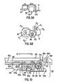
- Fig. 9 (A) is a plan view illustrating the positional relation between the loading pinion 50 shown in Fig. 5, swing plate 51, and the swing gear 52, and (B) is a side view illustrating the three positions of the swing plate 51.
- Fig. 10 is a side view illustrating the state of the swing plate 51 shown in Fig. 5 having rotated and the swing gear 52 being linked with the loading gear 54.
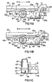
- Fig. 11 is a diagram illustrating the positional relation between the transporting plate 43 and the control plate 55 shown in Fig. 5, with (A) being a side view illustrating the time at which the control plate 55 begins to move, (B) being a side view illustrating the time at which movement of the control plate 55 is completed, and (C) being a side view illustrating (B) from a different direction.
- Fig. 12 is a plan view illustrating the position relation between the loading gear 54 shown in Fig. 5, the chucking plate 44, and the drive unit 70, wherein (A) illustrates the chucking disengagement state, and (B) illustrates the chucking state.
- Fig. 13 is a side view illustrating the positional relation between the chucking plate 44 and the loading gear 54 shown in Fig. 12, wherein (A) illustrates the chucking disengagement state, and (B) illustrates the chucking state.
- Fig. 14 is a side view illustrating the position relation between the chucking plate 44 and the drive unit 70 shown in Fig. 12, wherein (A) illustrates the chucking disengagement state, and (B) illustrates the chucking state.
- Fig. 15 (A) is a plan view illustrating both guide rails 59 and 60 attached to the loading unit 40 shown in Fig. 1, and (B) is a side view illustrating one guide rail 59.
- Fig. 16 (A) is a plan view of the starter rack 61 attached to the guide rail 59 and the starter link 62 shown in Fig. 15, and (B) is a side view.
- Fig. 17 is a diagram illustrating the positional relation between the starter rack 61 and starter link 62 shown in Fig 16, the swing gear 52, and the transporting plate 43 shown in Fig 8, with (A) being a plan view illustrating the state of the swing gear 52 meshing with the starter rack 61, (B) being a side view thereof, and (C) being a side view illustrating the state wherein the starter rack 61 has moved from the state shown in (B) and the starter link 62 has been rotated.
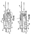
- Fig. 18 is a side view illustrating the gear mechanism 81 of the disk changer device relating to the second embodiment according to the present invention, in the initial state.
- Fig. 19 is a diagram illustrating the gear mechanism 81 shown in Fig. 18, showing a side view of a state wherein the transporting plate 82 of the gear mechanism 81 has moved in the X 1 direction from the state shown in Fig. 18 by a certain amount, enabling rotation of the swing gear 87.
- Fig. 20 is a diagram illustrating the gear mechanism 81 shown in Fig. 18, showing a side view of a state wherein the swing gear 87 of the gear mechanism 81 has rotated from the state shown in Fig. 19 and transfer of the output has been switched.
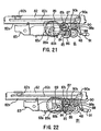
- Fig. 21 is a diagram illustrating the gear mechanism 81 shown in Fig. 18, showing a side view of a state wherein the loading gear 89 of the gear mechanism 81 has started driving of the chucking plate 83 from the state shown in Fig. 20.
- Fig. 22 is a diagram illustrating the gear mechanism 81 shown in Fig. 18, showing a side view of a chucking state wherein the loading gear 89 of the gear mechanism 81 has completed driving of the chucking plate 83 from the state shown in Fig. 21.
- Fig. 23 is a diagram illustrating the gear mechanism 81 shown in Fig. 18, showing a side view of a state wherein the swing gear 87 of the gear mechanism 81 has rotated from the state shown in Fig. 22 and transfer of the output has been switched.
- Fig. 24 is a diagram illustrating the gear mechanism 81 shown in Fig. 18, showing a side view of a state wherein the transporting plate 82 of the gear mechanism 81 has moved in the X 2 direction from the state shown in Fig. 23 by a certain amount.
- Fig. 25 is a diagram illustrating the transporting plate 82 driven by the gear mechanism 81 shown in Fig. 18, with (A) being a plan view and (B) being a side view.
- Fig. 26 is a diagram illustrating the chucking plate 83 driven by the gear mechanism 81 shown in Fig. 18, with (A) being a side view, (B) being a plan view, and (C) being a side view illustrating only the side wall having the cam groove 83b.
- Fig. 27 is a plan view illustrating the lock plate 90 of the gear mechanism 81 shown in Fig. 18.
- Fig. 28 is a plan view illustrating an example of a conventional disk changer device.
- Fig. 29 is a plan view illustrating the positional relation between the turntable and the disk holding member of the disk changer device shown in Fig. 28.
- Fig. 30 is a side view illustrating the driving construction of the transporting / chucking mechanism of the disk changer device shown in Fig. 28.
- Fig. 1 is a plan view illustrating a schematic construction of a disk changer device relating to a first embodiment of the present invention, this disk changer device being configured so as to work with a magazine 10 having a configuration such as illustrated in Fig. 2.
- the disk changer device is comprised of a base unit 20 which has functions of selecting the disk holding member and ejecting the magazine, a loading unit 40 which performs loading of the disk holding member, and a drive unit 70 which plays the disk.
- the base unit 20 is configured to movably support the leading unit 40 and mount the magazine 10 as shown in Fig. 2, and is arranged so as to vertically move the loading unit 40 as to the mounted magazine 10, thus conducting position with one of the disk holding members 11 of the magazine 10.
- the drive unit 70 is constructed of a drive plate 72 having a turntable 71, and a clamp arm 73 and so forth, and is rotatably attached to the loading unit 40 by means of a pair of rotation supporting members 74.
- X 1 denotes the direction of extracting the disk from the magazine 10
- X 2 denotes the direction of returning the disk to the magazine 10.
- Fig. 2 is an internal plan view illustrating the schematic construction of the magazine 10.
- a plurality of disk holding members 11 stored in a layered manner so as to be each extractable and replaceable.
- the disk holding member 11 is formed in a cylindrical shape which can store only one disk 12.
- the disk holding member 11 is provided with a disk insertion opening 11a situated on the side of the opening 10a of the magazine 10, and first and second fitting portions 11b and 11c which fit the loading unit 40.
- This disk holding member 11 is also provided internally with a holding arm 13 rotatably mounted by means of a shaft 13a, and a spring 14 which presses the holding arm 13 toward the disk holding side, and at the point that the disk 12 is inserted from the insertion opening 11a to the predetermined holding position shown in the Figure with a single-dot broken line, the disk 12 is held by the holding arm 13. Further, the side wall 10b inside the magazine 10 is constructed to come into contact with the side plane of the holding arm 13 so as to restrict the rotation thereof in the event that the disk holding member 11 is held, thereby preventing the disk 12 from falling.
- a pair of spring portions 15 for holding the plurality of disk holding members 11 individually, and a single-unit lock arm 16 for holding all of the plurality of disk holding members 11 all at once, these members being rotatable by means of shafts 15a and 16a.
- the lock arm 16 is provided in order to prevent the disk holding members 11 from falling out when not mounted to the device, and the lock is disengaged when the magazine 10 is mounted to the base unit 20 shown in Fig. 1.
- FIG. 3 is a plan view illustrating the schematic construction of the mounting portion of the magazine 10 and base unit 20.
- a locking groove 10d for locking the magazine 10 to the base unit 20 is provided at one edge of the base plane 10c of the magazine 10, shown in the Figure by a single-dot broken line.
- the base unit 20 shown in Fig. 1 by a single-dot broken line is comprised of a base plate 21, a shift motor 22 provided to the rear side of the base plate 21, a gear mechanism 22, and a shift link 24, and is also provided with a pair of shift plates 25 and 26 slidably provided to the inner plane of each of the inner walls 21a and 22b of the base plate 21.
- the shift link 24 is constructed so as to be rotatable around the shaft 24a via the gear mechanism 23, by means of driving by the shift motor 22.
- the shift plates 25, 26 respectively fit the pins 24b and 24c provided to the rotatable edges on both sides of the shift link 24, so as to slide along the side surface of the base plate according to the rotational direction of the shift link 24, thereby vertically moving the loading unit 40 and the drive unit 70 attached thereto.
- FIG. 4 are side views illustrating the elevating construction of the loading unit 40 by means of the shift plates 25 and 26.
- Fig. 4 (A) two stepped cam grooves 27a and 27b are formed to one shift plate 25, and as shown in Fig. 4 (B), the other shift plate 26 is provided with one stepped cam groove 27c.
- the stepped cam grooves 27a through 27c Inserted to each of the stepped cam grooves 27a through 27c are pins 42a through 42c provided to the chassis 41 of the loading unit 40.
- the loading unit 40 moves vertically accordingly to the horizontal movement of the cam groves 27a through 27c owing to the pair of shift plates 25 and 26 shifting horizontally, thereby being positioned at the height of a certain disk holding member 11 within the magazine 10.
- pins 42a through 42c of the loading unit 40 are also inserted into guide grooves 28a through 28c provided on the side walls 21a and 21b of the base plate 21 and extending vertically, thus serving not only as driving force transmitting means, but also as guiding means for the loading unit 40 as to the base plate 21.
- an ejecting plate 29 is provided to the rear side of the base plate 21 so as to be slidable in the Y direction intersecting the X axis at right angles, and further, a magazine loading plate 30 is provided slidably in the X direction.
- a contact portion 29a which comes into contact with one side plane of the magazine 10 inserted at the Y 1 direction as to the base unit 20.
- This ejecting plate 29 is pressed in the Y 2 direction which is the ejecting direction of the magazine 10, by means of a spring 31 provided between the ejecting plate 29 and the base plate 21.
- FIG. 3 is a plan view illustrating the positional relation between the magazine loading plate 30 and the shifting plate 25.
- a lock shaft 30a which fits to a locking groove 10d formed in the base surface 10c of the magazine 10 so as to lock the magazine 10
- a fitting portion 30b which fits the shift plate 25 is provided.
- This magazine loading plate 30 is pressed in the X 1 direction which is the locking direction of the magazine 10 by means of a spring provided between the magazine loading plate 30 and the base plate 21, and is also pressed in the X 2 direction which is the disengaging direction by means of the shift plate 25.
- a damper unit 33 for inhibiting the operation speed of the ejecting plate 29 so as to inhibit the shock generated between the ejecting plate 29 and the magazine 10, this damper unit 33 being linked with the ejecting plate 29.
- Fig. 5 is a diagram illustrating the principal components of the loading unit 40, with (A) being a plan view and (B) being a side view.
- the loading unit 40 is comprised of a transporting plate 43 (disk holding member transporting means) for transporting the disk holding members 11, a chucking plate 44 for driving a drive plate 72 and clamp arm 73, a driving block 45 for driving the plates 43 and 44, and so forth.
- the transporting plate 43 and the chucking plate 44 are both provided slidable in the X direction as to the chassis 41.
- the transporting plate 43 is provided with a rack (transporting driving rack) 43a which is linked with a later-described loading pinion 50 of the driving block 45, an arm unit 43b for pressing the first and second fitting portions 11b and 11c of the disk holding member 11, and a cam groove 43c for controlling the rotational position of a later-described swing plate 51.
- a fitting groove 44a for fitting with later-described loading gear 54 of the driving block 45.
- the driving block (driving means) 45 is comprised of a motor bracket 46 fixed to the chassis 41, a loading motor (driving source) 47 attached to this motor bracket 46, and a plurality of types of gears and movable plates for transferring the output of this loading motor 47 to the transporting plate 43 and chucking plate 44 in a separate and selective manner.
- driving block 45 is comprised of a motor bracket 46 fixed to the chassis 41, a loading motor (driving source) 47 attached to this motor bracket 46, and a plurality of types of gears and movable plates for transferring the output of this loading motor 47 to the transporting plate 43 and chucking plate 44 in a separate and selective manner.
- Fig. 6 is a diagram illustrating the configuration of the driving block 45, with (A) being a plan view and (B) being a side view.
- the driving block 45 is comprised of a motor bracket 46 and a loading motor 47, and further a worm mechanism 48, pinion shaft 49, loading pinion 50, swing plate 51, swing gear 52, linkage gear 53, loading gear 54, control plate 55, and so forth.
- a worm mechanism 48 which passes through the main wall of the motor bracket 46 which extends parallel to the loading motor 47, and extends to the opposite side of the loading motor 47.
- a pinion shaft 49 is provided to the main wall of the motor bracket 46, attached so as to extend to the opposite side of the loading motor 47, with a loading pinion (output gear) 50 which drives the transporting plate 43 being attached to this pinion shaft 49.
- This loading pinion 50 is comprised of a large diameter gear member and a small diameter gear member, with the large diameter gear member perpetually meshing with the worm mechanism 48, and the small diameter gear member perpetually meshing with a later-described swing gear 52 and also meshing with the rack 43a of the transporting plate 43. i.e., the output of the loading motor 47 is transferred to this loading pinion 50 via the worm mechanism 48, so as to drive the transporting plate 43 in the X direction.
- the pinion shaft 49 is provided with the swing plate 51 so as to press against the loading pinion 50, and so as to rotate in the direction of rotation of the loading pinion 50.
- a position restricting pin 51a is provided to one rotational free end of the swing plate 51, so as to be inserted into the cam groove 43c of the transporting plate 43 and thus restricting the rotational position of the swing plate 51.
- a swing gear (planetary gear) 52 is provided to the other rotational free end of the swing plate 51.
- This swing gear 52 is comprised of a large diameter gear member and a small diameter gear member, with the large diameter gear member perpetually meshing with the small diameter gear member of the loading pinion 50, and the small diameter gear member being capable of meshing with the linkage gear 53 depending on the rotational position of the swing plate 51.
- This linkage gear 53 is perpetually meshing with the loading gear 54, these gears 53 and 54 both being attached to the motor bracket 46.
- the loading gear (chucking driving gear) 54 comprises on one side a cam 54a for driving the control plate 55, and comprises on the other side a driving pin 54b for driving the chucking plate 44.
- This driving pin 54b is inserted into the fitting groove 44a of the chucking plate 44 as shown in Fig. 5 (B), and is arranged so as to drive the chucking plate 44 in the X direction according to rotation of the loading gear 54.
- Fig. 7 is a diagram illustrating the positional relation between the loading gear 54 of the driving block 45, the control plate 55, and the motor bracket 46.
- (A) is a plan view
- (B) is a side view.
- the control plate 55 is positioned so as to overlap with the main wall of the motor bracket 46, and is provided so as to be slidable in the X direction as to the motor bracket 46.
- This control plate 55 is provided with a fitting potion 55a which fits to the cam 54a of the loading gear 54, and a pressing portion 55b which presses the later-described transporting plate holder 57.
- the control late 55 is pressed in the X 2 direction which is the direction of contact with the cam 54a of the loading gear 54, by means of the spring 56 provided between the control plate 55 and the motor bracket 46.
- Fig. 8 is a diagram illustrating the positional relation between the swing plate 51 of the driving block 45 and The transporting plate 43, (A) being a plan view, and (B) being a side view.
- the transporting plate 43 is a member which extends in the X direction which is the sliding direction thereof, and the rack 43a and the cam 43c are formed so as to extend in the X direction following this transporting plate 43.
- a gullet 43d for disengaging the transporting plate 43 from the loading pinion 50 of the driving block 45 is provided to the end potion of the rack 43a, and a release portion 43e for releasing the position restricting pin 51a so as to allow the swing plate 51 to rotate in the case that the loading pinion 50 has reached the gullet 43d of the transpiration plate 43 is provided to the cam groove 43c.
- a fitting portion 43f for fitting with a later-described transporting plate holder 57 is provided near the release portion 43e of the transporting plate 43.
- Fig. 9 (A) is a plan view illustrating the positional relation between the loading pinion 50, swing plate 51, and the swing gear 52
- Fig. 9 (B) is a side view illustrating the three positions of the swing plate 51.
- the swing plate 51 is arranged so as to take three positions, namely an idling position P 1 which is an intermediate position, and on either side thereof are the chucking position P 2 and the eject position P 3 .
- Fig. 8 (B) shows the position of the position restricting pin 51a corresponding to such positions of the swing plate 51.
- Fig. 10 is a side view illustrating the state of the swing plate 51 having rotated and the swing gear 52 being linked with the loading gear 54, partway though the disk loading operation. i.e., at the initial state of disk loading, the swing plate 51 which had been restricted to the idling position P 1 as shown in Fig 8 (B) is rotated in the rotational direction of the loading pinion 50, and moves to the chucking position P 2 .
- Fig. 11 is a diagram illustrating the positional relation between the transporting plate 43 and the control plate 55, with (A) being a side view illustrating the time at which the control plate 55 begins to move, (B) being a side view illustrating the time at which movement of the control plate 55 is completed, and (C) illustrating (B) from a different direction.
- rotatably provided to the output plane of the transporting plate 43 of the loading shaft 49 is a transporting plate holder 57 for moving the transporting plate 43 after being disengaged from the loading pinion 50 and holding the transporting plate 43 at this position.
- This transporting plate holder 57 is provided with a spring-like fitting portion 57a which is pressed in the X 1 direction by means of the pressing portion 55b of the control plate 55, and a pressing portion 57b which presses the fitting portion 43f of the transporting plate 43 in the X 1 direction. Also, the transporting plate holder 57 is pressed by means of a transporting plate holder spring 58 provided between the transporting plate holder 57 and the chassis 41, so as to press the transporting plate 43.
- Fig. 12 is a plan view illustrating the position relation between the loading gear 54 of the driving block 45, the chucking plate 44, and the drive unit 70
- Fig. 13 is a side view illustrating the positional relation between the chucking plate 44 and the loading gear 54
- Fig. 14 is a plan view illustrating the position relation between the chucking plate 44 and the drive unit 70.
- (A) illustrates the chucking disengagement state
- (B) illustrates the chucking state, respectively.
- the driving pin 54b of the loading ear 54 is inserted into a fitting groove 44a provided to one side wall of the chucking plate 44, so that the chucking plate 44 is driven in the X direction by means of driving pin 54b moving in the X direction according to rotation of the loading gear 54.
- a fitting groove 44b is provided to the other side wall of the chucking plate 44 with a pin 72a attached to the side surface of the drive plate 72 being inserted into the cam groove 44b, this drive plate 72 being vertically movable by means of the X-directional movement of the chucking plate 44.
- a pressing portion 44c which presses the contact portion 73a provided to the clamp arm 73 in the chucking disengaging direction.
- a spring 75 is provided between the clamp arm 73 and the chassis 41, pressing the clamp arm 73 in the chucking direction.
- Fig. 15 (A) is a plan view illustrating both guide rails 59 and 60, and (B) is a side view illustrating one guide rail 59.
- two spring-like pinching portions 59a and 59b are provided to the one guide rail 59, and a single spring-like pinching portion 60a is provided to the other guide rail 60.
- These spring-like pinching portions 59a, 59b, and 60a are each formed of a pair of vertically opposing finger-like members, as shown in Fig.
- a positioning portion 59c which performs positioning of the disk holding member 11 in the X direction by coming into contact with the edge surface of the first fitting portion 11b of the disk holding member 11, and a positioning portion 59d which performs positioning of the disk holding member 11 in the Y direction by coming into contact with the side surface of the disk holding member 11.
- a starter rack 61 and starter link 62 for meshing the transporting plate 43 with the loading pinion 50.
- (A) in Fig. 16 is a plan view
- the starter rack 61 is an elongated member extended in the X direction, and is slidably attached to the guide rail 59.
- the starter link 62 is attached so as to be rotatable around the shaft 62a attached to the guide rail 59.
- Fig. 17 is a diagram illustrating the positional relation between the starter link 62, the swing gear 52, and the transporting plate 43, with (A) being a plan view illustrating the state of the swing gear 52 meshing with the starter rack 61, (B) being a side view thereof, and (C) being a side view illustrating the state wherein the starter rack 61 has moved from the state shown in (B) and the starter link 62 has been rotated.
- the starter rack 61 is provided with a fitting groove 61a so as to fit with the starter link 62, and a tooth 61b capable of engaging the swing gear 52, whereby the starter rack 61 meshes with the swing gear 52 and moves in the X 1 direction, and rotates the starter link 62.
- the starter link 62 is comprised of a pin 62b inserted into the fitting groove 61a of the starter rack 61, and a pressing portion 62c for pressing the arm unit 43b of the transporting plate 43, and also is pressed in a non-pressing direction by means of a spring 63 provided between the starter link 62 and the guide rail 59.
- this starter link 62 is arranged so that when it is rotated by the movement of the starter rack 61 in the X 1 direction, the pressing portion 62c thereof presses the arm unit 43b of the transporting plate 43 in the X 2 direction, thus moving the transporting plate 43.
- operations of mounting the magazine operations of selecting the disk holding member, operations of disk loading, operations of disk ejecting, and operations of ejecting the magazine can be performed well.
- the disk loading operation and the disk ejecting operation share much in common. The following is separate descriptions of the details of each operation and the initial state before operation, and the commonness between the disk loading operation and the disk ejecting operation.
- the height of the base surface 10c of the magazine 10 shown in fig. 3 and the X-directional position thereof is positioned as to the base plate 21, and then the magazine 10 is slid in the Y 1 direction.
- the side on the Y 1 direction comes into contact with the contact portion 29a of the ejecting plate 29 provided to the base plate 21. Accordingly, the ejecting plate 29 is pressed against the force of the spring 31 and thus the magazine 10 is moved to the predetermined mounting position as shown in Fig. 3.
- the lock shaft 30a of the magazine locking plate 30 provided to the base plate 21 enters the depth of the fitting groove 10d provided to the base surface 10c of the magazine 10 via the slanted side surface thereof, so that the magazine 10 is locked to the mounting position thereof by means of the magazine locking plate 30.
- the shift link 24 is driven by means of rotation of the shift motor 22 shown in Fig. 1 by means of the gear mechanism 23, and this shift link is moved by a certain mount in a certain direction corresponding with the disk holding member 11 which is the object of this shift link 24. Consequently, the pair of shift plates 25 and 26 which are fit to either side of the shift link 24 via pins 24b and 24c move in the X 1 direction or the X 2 direction according to the direction and amount of rotation of the shift link 24, by a certain amount. Also, in this case, the pair of shift plates 25 and 26 are driven in opposite direction. Then, accompanying the movement of this pair of shift plates 25 and 26 in the X direction, the loading unit 40 is vertically driven via the cam grooves 27a through 27c shown in Fig. 4 and the pins 42a through 42c thereof, thus positioning the loading unit 40 at the height corresponding with the disk holding member 11 in question.
- the transporting plate 43 In the initial state before disk loading, the transporting plate 43 is at the most X 2 direction-wise position, as shown in Fig. 8 (B), and the rack 43a thereof meshes with the loading pinion 50 at the farthest X 1 direction-wise end. Also, the position restricting pin 51a of the swing plate 51 is at the farthest X 1 direction-wise end of the cam groove 43c of the transporting plate 43, with the swing plate 51 being restricted at the idling position P 1 . Consequently, the small diameter gear member of the swing gear 52 is not meshed with the linkage gear 53, as shown in Fig. 6 (B), and as a result, is disengaged from the loading gear 54.
- the large diameter gear member of the swing gear 52 is also disengaged from the starter rack 61 as shown in Fig. 17, so that the starter link 62 is at a counter-clockwise directional position such as shown in Fig. 17 (B), due to the pressing of the spring 63.
- the leading end of the arm unit 43b of the transporting plate 43 is between the first and second fitting portions 11b and 11c (Fig. 2) of the selected disk holding member 11.
- the chucking plate 44 is at the most X 2 direction-wise position, so as shown in Fig. 14 (A), the drive unit 70 is in a chucking disengagement state wherein the clamp arm 73 and the drive plate 72 are vertically distanced. i.e., the clamp arm 73 has the contacting portion 73a thereof fitting the pressing portion 44c of the chucking plate 44, and is held in an upward position by means of this pressing portion 44c. Also, the drive plate 72 has the pin 72a thereof below the cam groove 44b of the chucking plate 44, and thus is held in a lower position.
- the disk holding member 11 is selected by the aforementioned selecting operation, and then a disk loading operation is performed, this disk loading operation comprising a three-step operation of: (1) operation of extracting the disk holding member; (2) operation of chucking the disk; and (3) operation of returning the disk holding member.
- this disk loading operation comprising a three-step operation of: (1) operation of extracting the disk holding member; (2) operation of chucking the disk; and (3) operation of returning the disk holding member.
- the loading motor 47 shown in Fig. 5 (A) is rotated in the predetermined direction, the output thereof is transferred to the loading pinion 50 via the worm mechanism 48, and the loading pinion 50 is rotated in a counter-clockwise direction in the Figure, as shown by an arrow in Fig. 8 (B).
- the transporting plate 43 moves in the X 1 direction via the rack 43a, and the leading end of the arm unit 43b presses out the first fitting member 11b of the disk holding member 11, thus extracting the disk holding member 11 holding the disk 12 from the magazine 10.
- the position restricting pin 51a of the swing plate 51 reaches the release portion 43e of the cam groove 43c and becomes rotatable, as shown in Fig. 10, so the swing plate 51 rotates on a counter-clockwise direction according to the rotational direction of the loading pinion 50, and moves from the idling position P 1 to the chucking position P 2 .
- the loading pinion 50 reaches the gullet 43d of the transporting plate 43, so the transporting plate 43 stops approximately 1 mm before the predetermined transporting position.
- the swing gear 52 meshes with the linkage gear 53 by means of the swing plate 51 rotating to the chucking position P 2 and is linked with the loading gear 54, so a driving path is formed, starting with the loading pinion 50, passing through the swing gear 52 and linkage gear 53, and reaching the loading gear 54. i.e., the loading being begins clockwise rotation by means of rotation of the loading pinion 50 in the counter-clockwise direction, via this driving path.
- the control plate 55 starts motion in the X 1 direction via a cam 54a formed on one side thereof and a contact portion 55a, as shown in Fig. 11 (A).
- the pressing portion 55b presses the spring-like fitting portion 57a of the transporting plate holder 57 as shown in Fig. 11 (B), so as to rotate the transporting plate holder 57. Due to the rotation of this transporting plate holder 57, the pressing portion 57b thereof presses out the fitting portion 43f of the transporting plate 43, thereby moving the transporting plate 43 approximately 1 mm in the X 1 direction, thus reaching the predetermined transporting position.
- the control plate 55 moves in the X 1 direction with the loading gear 54 rotating 90 , and then moves in the X 1 direction with the loading gear 54 rotating the next 90 , thus returning to the initial position. i.e., the control plate 55 makes one reciprocal movement in the X direction with one 180 rotation of the leading gear 54.
- the transporting plate holder 57 does not follow the movement of the control plate 55 in the X 2 direction, but is held by the force of the transporting plate holder spring 58, and thus the transporting plate 43 is maintained at the predetermined transporting position until the transporting plate 43 is driven again.
- the driving pin 54b formed on the side of the loading gear 54 opposite to the side on which the cam 54a is formed begins to move in the X 1 direction, and thereby the chucking plate 44 begins to move in the X 1 direction via the driving pin 54b and fitting groove 44a.
- the clamp arm 73 and the driving plate 72 which were in the chucking disengaging state opened vertically, perform the chucking operation.
- the clamp arm 73 has the contact portion 73a thereof released from the pressing portion 44c of the chucking plate 44, thereby rotating downwards by means of the pressing force of the spring 75, and the driver plate 72 has the pin 72a thereof rise through the cam groove 44b, thereby rotating upwards.
- the chucking of the disk 12 onto the turntable 71 is completed at the point that the leading gear 54 has rotated 180 and the chucking plate 44 has moved farthest in the X 1 direction.
- the disk holding member extracted from within the magazine 10 as described above is guided by a pair of guide rails 59 and 60, as shown in Fig. 15.
- a pair of guide rails 59 and 60 as shown in Fig. 15.
- height offset is absorbed by the three spring-like pinching portions 59a, 59b, and 60a provided to the guide rails 59 and 60, and the disk holding member 11 is held at a constant height.
- the disk holding member 11 is pressed against the positioning portion 59c of the guide rail 59 by means of slight final movement of the transporting plate 43 at the time of the chucking operation, thereby conducting positioning thereof in the X direction. Also, by means of the side of the disk holding member 11 being pressed against the positioning portion 59c of the guide rail 59, positioning thereof in the Y direction is also carried out. Thus, positioning of the disk holding member 11 in the height direction and X/Y directions can be automatically conducted in an excellent manner at the time of transporting the disk holding member 11 by means of a pair of guide rails 59 and 60, thereby enabling chucking operation to be conducted in a desirable manner at an optimal position.
- inverse rotation of the loading motor 47 causes the loading pinion 50, which had rotated in a counter-clockwise direction such as shown in Fig. 10 during the chucking operation, to rotate in a clockwise direction.
- the position restricting pin 51a of the swing plate 51 is situated at the release portion 43e of the cam groove 43c, so the swing plate 51 rotates in a clockwise direction according to the direction of rotation of the loading pinion 50, so as to move to an eject position P 3 such as shown in Fig. 17 (B), and the swing gear 52 meshes with the tooth 61b of the starter rack 61 at the large diameter gear member.
- the transporting plate 43 moves in the X 2 direction by means of the clockwise rotation of the loading pinion 50, and the leading end of the arm unit 43b presses out the second fitting portion 11c of the disk holding member 11, thereby returning the disk holding member 11 into the magazine 10.
- the swing plate 51 is returned from the eject position P 3 to the idling position P 1 once more by means of the cam groove 43c, and thus the swing gear 52 is maintained at a state disengaged from the loading gear. Consequently, the loading gear 54 is held at a stopped state, so the drive unit 70 is held in a chucking state as shown in Fig. 14 (B).
- the disk holding member 11 moves in the X 2 direction which is the returning direction to the magazine 10
- the disk 12 is chucked on the turntable 71 in a sure manner, so the disk 12 remains on the turntable 71 having been extracted from the disk holding member 11, by means of the holding arm 13 of the disk holding member 11 rotating out of the way. Accordingly, the disk holding member 11 alone is returned into the magazine 10.
- this disk ejecting operation comprising a three-step operation of: (4) operation of extracting the disk holding member, (5) operation of disengaging disk chucking, and (6) operation of returning the disk holding member.
- This disk ejecting operation is as described below.
- the operation of extracting the disk holding member 11 when performing the disk ejecting operation is basically the same as the operation of extracting the disk holding member 11 when performing the disk loading operation. i.e., the loading motor 47 shown in Fig. 5 (A) is rotated in the predetermined direction, and the loading pinion 50 is rotated in a counter-clockwise direction in the Figure, as shown by the arrow in Fig. 8 (B), thereby moving the transporting plate 43 in the X 1 direction via the rack 43a, thus extracting the disk holding member 11 from the magazine 10.
- the disk holding member 11 extracted from the magazine 10 is not a disk holding member 11 holding the disk 12, but an empty disk holding member 11, and that the disk 12 on the turntable 71 is inserted into the holding member 11, and thus is stored within the disk holding member 11. i.e., once the holding arm 13 of the holding member 11 is pushed outwards temporarily, the disk 12 is stored within the disk holding member 11 by means of this holding arm 13 and spring 14.
- the loading gear 54 which has been rotated 180 at the time of the chucking operation is further rotated 180 so as to return to the initial position and thus perform chucking disengagement operation. Except for this, the basic flow of the operations of the driving block 45 is the same as that at the time of the operation of disk loading.
- the swing plate 51 rotates in the counter-clockwise direction as shown in Fig. 10, and moves from the idling position P 1 to the chucking position P 2 .
- the loading pinion 50 reaches the gullet 43d of the transporting plate 43, so the transporting plate 43 stops approximately 1 mm before the predetermined transporting position.
- the swing gear 52 meshes with the linkage gear 53 by means of rotation of the swing plate 51, and is linked with the loading gear 54, so the loading gear 54 starts rotation in the clockwise direction by means of the loading pinion 50 rotating in the counter-clockwise direction.
- the loading gear 54 is at a position rotated 180 from the initial position as shown in Fig. 13 (B), and therefore the loading gear 54 performs an operation of rotating 180 further from this position, thus returning to the initial position.
- the control plate 55 returns to the X direction exactly in the same manner of the first half rotation of 180 of the loading gear, owing to the form of the cam 54a of the loading gear 54. i.e., the control plate 55 presses the transporting plate 43 out to the predetermined transporting position via the transporting plate holder 57, and the returns to the initial position.
- the driving pin 54b of the loading gear 54 and the catching plate 44 fit thereto are at the most X 1 direction-wise position, as shown in Fig. 13 (B), so the chucking plate 44 moves in the X 2 direction accompanying the later half 180 rotation of the loading gear 54, reverse to the first half 180 rotation.
- the clamp arm 73 and the drive plate 72 which were in the chucking state as shown in Fig. 14 (B), perform chucking disengaging operation.
- the clamp arm 73 has the contact portion 73a thereof fit again to the pressing portion 44c of the chucking plate 44, thereby rotating by being lifted up.
- the drive plate 72 rotates downwards by means of the pin 72a thereof descending through the cam groove 44b. Consequently, as shown in Fig. 14 (A), the loading gear 54 rotates 180 and returns to the initial position, and at the point that the chucking plate 44 has moved to the most X 1 direction-wise position, the chucking disengagement of the disk 12 from the turntable 71 is completed.
- the operation of guiding the disk holding member during the disk ejecting operation is exactly the same as that during the disk loading operation. i.e., positioning of the disk holding member 11 in the height direction and X/Y directions can be automatically conducted in an excellent manner by means of a pair of guide rails 59 and 60.
- the disk 12 which had been chucked on the turn table 71 can be inserted into this disk holding member 11 at an optimal position, thereby holding the disk 12 within the disk holding member 11 in a sure manner.
- the operation of returning the disk holding member 11 during the disk ejecting operation is basically the same as the operation of returning the disk holding member 11 during the aforementioned disk loading operation. i.e., at the point that chucking of the disk 12 has been completed, inverse rotation of the loading motor 47 causes the loading pinion 50 to rotate in a clockwise direction, causing the swing plate 51 to rotate in a clockwise direction, so as to move to an eject position P 3 such as shown in Fig. 17 (B), and meshes with the tooth 61b of the starter rack 61.
- the transporting plate 43 moves in the X 2 direction by means of the clockwise rotation of the loading pinion 50, thereby returning the disk holding member 11 into the magazine 10.
- the swing plate 51 is returned from the eject position P 3 to the idling position P 1 once more by means of the cam groove 43c of transporting plate 43, and thus the swing gear 52 is maintained at a state disengaged from the loading gear 54. Consequently, the drive unit 70 is held in a chucking disengagement state as shown in Fig. 14 (A).
- the disk holding member 11 moves in the X 2 direction which is the returning direction to the magazine 10
- the disk 12 stored in the disk holding member 11 returns into the magazine 10 along with the disk holding member 11, since the disk 12 is released from the drive unit 70.
- the transporting plate 43 is directly driven via the rack 43a by means of rotation of the loading pinion 50 in the counter-clockwise direction, thereby extracting the disk holding member 11 from the magazine 10 and transporting it to the predetermined transporting position, following which the transporting plate 43 is automatically disengaged by means of the gullet 43d.
- the swing gear 52 is linked to the loading gear 54, and the chucking plate 44 is driven to the going path or returning path via the first half or latter half 180 rotation of the loading gear by means of the counter-clockwise rotation of the loading pinion 50, thereby performing chucking of the disk 12 or disengagement thereof according to the direction of motion of this chucking plate 44.
- the loading pinion 50 is inversely rotated in the clockwise direction, thereby disengaging the loading gear 54 and maintaining the position of the chucking plate 44, and also meshing the loading pinion 50 with the rack 43a once more so as to drive the transporting plate 43 in the reverse direction, thereby returning the disk holding member 11 into the magazine 10.
- a 1-to-1 corresponding relation is constantly maintained between the rotation direction of the loading pinion 50 which is the output gear and the operating direction of the transporting plate 43 which is the disk holding member transporting means in both the disk loading operation and the disk ejecting operation, and is arranged so that only the operating direction of the chucking plate 44 switches alternately each time the loading gear 54 rotates 180 , as to the loading pinion 50 rotating in the same direction.
- the transporting plate 43 while the transporting plate 43 is caused to make one reciprocal movement to perform extracting / returning operation of the disk holding member 11, the chucking plate 44 can be driven on the going path or the returning path to perform chucking operation of chucking disengagement operation. Accordingly, the transporting plate 43 is caused-to carry out the same reciprocal movement at all times by means of a certain rotation control of causing the loading pinion 50 to rotate in the first direction by a certain amount and then causing the loading pinion 50 to rotate in the second direction by a certain amount, and further, the chucking plate 44 can be caused to alternately perform chucking operation and chucking disengagement operation.
- the shift link 24 is rotated to the end portion of the rotation range thereof, by means of rotation of the shift motor 22 shown in Fig. 1. Consequently, as shown in Fig. 3 (B), the shift plate 25 moves to the farthest end in the X 2 direction within the movement range thereof, presses the fitting portion 30b of the magazine locking plate 25, thus moving the magazine locking plate 25 in the X 2 direction.
- the lock shaft 30a is released from the fitting groove 10d provided to the base surface 10c of the magazine 10 ° , the eject plate 29 moves in the Y 2 direction by means of the force of the spring 31, ejecting the magazine 10.
- the operation speed of the ejecting plate 29 is inhibited by the damper unit 33, so the shock generated between the ejecting plate 29 and the magazine 10 can be sufficiently inhibited, thus ejecting the magazine 10 in a desirable manner.
- a 1-to-1 corresponding relation can be constantly maintained between the rotation direction of the loading pinion 50 which is the output gear and the operating direction of the transporting plate 43 which is the disk holding member transporting means in both the disk loading operation and the disk ejecting operation. Accordingly, control is easy, and even in the event that the power is turned off the operation being performed before power outage can be resumed, thus facilitating securing of continuity of control.
- the transporting plate 43 is caused to carry out the same reciprocal movement at all times by means of a certain rotation control of causing the loading pinion 50 to rotate in the first direction by a certain amount and then causing it to rotate in the second direction by a certain amount, and further, the chucking plate 44 is caused to alternately perform chucking operation and chucking disengagement operation, thereby enabling alternately performing disk loading operation and disk ejecting operation. i.e., control is further simplified, since disk loading operation and disk ejecting operation can be alternately performed by means of the same rotation control of the loading pinion 50.
- each member comprising the driving block 45 is sufficiently small, and even taking operation space into consideration, this does not effect the dimensions of the lading unit 40.
- the number of parts comprising the driving block 45 is few, and the configuration is simplified. Accordingly, the overall device can be reduced in size and complexity due to such a small and simplified structure of the driving block 45, and the operational reliability thereof is also excellent.
- the magazine is constructed so as to be detachably provided to the device proper, and thus is advantageous in that replacement of the disks 12 can be easily performed by removing the magazine 10 from the device. Further, it is possible to use a magazine 10 which is separate from this magazine 10, this magazine 10 having a plurality of disks 12 stored therein beforehand, and in such a case, a plurality of disks 12 can be changed all at once simply by replacing the magazine 10.
- Fig. 18 through Fig. 24 are side views progressively illustrating different operation states of the gear mechanism 81 of the disk changer device relating to the second embodiment according to the present invention, with Fig. 18 shown in the initial state.
- the gear mechanism according to the present embodiment is a simplified from of the driving force transferring system (selecting mechanism) of the loading unit in the above-described first embodiment.
- the forms of the transporting plate 82 which is driven by the gear mechanism 81 and the chucking plate 83 likewise, are changed somewhat.
- the transporting plate 82 is provided with a rack 82a which does not have a gulleted portion, an arm unit 82b which fits with the disk holding member, and an L-shaped cam groove 82c extending in the X direction.
- a fitting groove 83a for fitting with a later-described loading gear 89 of the gear mechanism 81 is provided to one wall of the chucking plate 83.
- a cam groove 83b is provided to the other wall of the chucking plate 83 for driving a drive unit 70 such as illustrated in Fig.
- the form of the cam groove 83b is arranged so as to cause the drive unit to perform chucking operation by moving from the position at the direction X 1 in the Figure of the chucking plate to the direction X 2 in the Figure.
- the following is a detailed description of the construction of the gear mechanism 81.
- the gear mechanism 81 is comprised of a pinion shaft 84, loading pinion 85, swing plate 86, swing gear 87, linkage gear 88, loading gear 89, lock plate 90, etc.
- the pinion shaft 84 is attached to a main wall or the like of the motor bracket as shown in Fig. 5, and a loading pinion (output gear) 85 is provided to this pinion shaft 84.
- This loading pinion 85 is constructed from a large diameter gear member and a small diameter gear member, being linked to a loading motor (driving source) 47 such as shown in Fig. 5 via a worm mechanism 48 or the like such as shown in Fig. 19 through Fig. 25 by means of the outer diameter gear member, and also is perpetually meshed with a later-described swing gear 87 by means of the small diameter gear member.
- the pinion shaft 85 is provided with a swing plate 86 so as to press against the loading pinion 85, and rotated in the rotation direction of the loading pinion 85.
- a swing gear 87 is provided to the rotational free end of this swing plate 86, and a linkage gear 88 and loading gear 89 are positioned in an opposing manner with this swing gear 87 between.
- the swing gear 87 perpetually meshes with the loading pinion 85 and selectively meshes with the linkage gear 88 and loading gear 89 according to the rotational position.
- the swing gear 87 is arranged such that in the event that the swing gear 87 has rotated in the clockwise direction in the Figure, it is meshed with the linkage gear 88 in the first rotational position as shown in Fig. 18, and in the event that the swing gear 87 has rotated in the counter-clockwise direction in the Figure, it is meshed with the loading gear 89 in the second rotational position as shown in Fig. 20.
- the linkage gear 88 is perpetually meshed with the rack 82a of the transporting plate 82, and is arranged so as to drive the transporting plate 82 in the X direction in the Figure by means of meshing with the swing gear 87 and rotating.
- X 1 and X 2 each indicate the extracting direction of the disk and the returning direction thereof.
- the loading gear (chucking driving gear) 89 has a driving pin 89a for driving the chucking plate 83. This driving pin 89a is inserted into the fitting groove 83a of the chucking plate 83, as shown in Fig.
- the width dimensions in the X direction of the fitting groove 82a of the chucking plate 83 is set at around twice the diameter of the driving pin 89a, thereby the driving pin 89a driving the chucking plate 83 only at the central portion of the end position of the X 1 direction to the end position of the X 2 direction, being arranged so as to release the chucking plate 83 near each end position.
- the lock plate 90 is rotatably provided to the shaft 88a of the linkage gear 88.
- a position restricting pin 90a is provided to one rotational free end of this lock plate 90, so as to be inserted into the cam groove 82 of the transporting plate 82 and restrict the rotational position of the lock plate 90.
- an L-shaped lock groove 90b formed of a side portion and a narrow portion, with a locked pin 87a equivalent to the shaft of the swing gear 87 being inserted into this lock groove 90b.
- the lock plate 90 is held at the clockwise direction locking position in the Figure by means of position restricting of the position restricting pin 90a by the long narrow-width portion of the cam groove 82c when the transporting plate 82 is moving in the X direction, and as shown in Fig. 19, the position restricting pin 90a can be moved to the counter-clockwise direction disengaging position in the Figure by means of the short wide-width portion of the cam groove 82c when transporting of the transporting plate 82 is completed.
- the lock plate 90 is at a locking position as shown in Fig.
- the lock plate 90 locks the locked pin 87a of the swing gear 87, thereby locking the swing gear 87 to the first rotational position (a position meshing with the linkage gear 88) by means of the narrow-width portion of the lock groove 90b. Also, at the disengaging position as shown in Fig. 19, the lock plate 90 releases the locked pin 87a of the swing gear 87, thus enabling the swing gear 87 to move to the second rotational position (a position meshing with the loading gear 89) by means of the wide-width portion of the lock groove 90b. In this case, the lock plate 90 is pressed to the release position side which is the counter-clockwise direction in the Figure, by means of a spring 91 provided between the lock plate 90 and the chassis 41, as shown in Fig. 5.
- the transporting plate 82 and the linkage gear 88 are perpetually meshed, and a gullet is not provided to the rack 82a of the transporting plate 82, so there is no provision of members for performing moving or holding of the transporting plate 82 following disengagement by gulleting, nor is there provision of members for re-meshing with the driving side. i.e., members used in the first embodiment such as the control plate 55 and transporting plate holder 57, or starter rack 61 and starter link 62, etc. are omitted in the present embodiment.
- the units other than the loading unit 40 i.e., the magazine 10 and base unit 20, and the drive unit 70 and so forth are constructed exactly the same as the first embodiment.
- disk loading operation and disk ejecting operation can be conducted in a desirable manner. Also, the same as with the first embodiment, there is also a high degree of commonly shared items in the disk loading operation and the disk ejecting operation. The following is separate descriptions of the details of each operation and the initial state before operation, and the commonness between the disk loading operation and the disk ejecting operation.
- the transporting plate 82 In the initial state before disk loading, as shown in Fig. 18, the transporting plate 82 is at the most X 2 direction-wise position, and the rack 82a thereof is meshed with the linkage gear 88 at the end in the X 1 direction. Also, the position restricting pin 90a of the lock plate 90 is at the end of the cam groove 82c of the transporting plate 82 in the X 1 direction, the lock plate 90 being restricted at the locking position. Accordingly, the locked pin 87a of the swing gear 87 is situated at the narrow-width portion of the lock groove 90b, the swing gear 87 being restricted to the first rotational position, and engaged with the linkage gear 88.
- a chucking plate 83 which is not shown in this Figure 18 is also at the X 1 direction position, and the drive unit 70 is at a chucking disengaging state such as shown in Fig. 14 (A).
- a disk holding member 11 such as illustrated in Fig. 2 is selected by procedures such as described with the above-described first embodiment, and then and then a disk loading operation is performed, this disk loading operation comprising a three-step operation of: (1) operation of extracting the disk holding member; (2) operation of chucking the disk; and (3) operation of returning the disk holding member.
- this disk loading operation comprising a three-step operation of: (1) operation of extracting the disk holding member; (2) operation of chucking the disk; and (3) operation of returning the disk holding member.
- the loading motor 47 shown in Fig. 5 is rotated, causing the loading pinion 85 to be rotated in a counter-clockwise direction in the Figure, as shown by an arrow in Fig. 18.
- the transporting plate 82 moves in the X 1 direction via the swing gear 87, linkage gear 88, and rack 82a, and the leading end of the arm unit 82b presses out the disk holding member 11 shown in Fig. 2, thus extracting the disk holding member 11 holding the disk 12 from the magazine 10.
- the position restricting pin 90a of the lock plate 90 reaches the wide-width portion of the cam groove 82c and becomes rotatable, as shown in Fig. 19, so the lock plate 90 rotates to the release position by means of the force of the spring 91. Consequently, the locked pin 87a of the swing gear 87 reaches the wide-width portion of the lock groove 90b and becomes rotatable, so the swing gear 87 rotates in a counter-clockwise direction according to the rotational direction of the loading pinion 85 and is disengaged from the linkage gear 88, and as shown in Fig. 20, meshes with the loading gear 89 at the second rotational position. Accordingly, subsequently, accompanying the rotation to the counter-clockwise direction in the Figure of the loading pinion 85 in the Figure, the loading gear 89 begins rotating in the counter-clockwise direction in the Figure, via the swing gear 87.
- the driving pin 89a which was situated at the X 1 direction position at the initial state begins movement-to the X 2 direction, as shown in Fig. 21, and thus the chucking plate 83 begins movement to the X 2 direction, via the driving pin 89a and the fitting groove 83a.
- the width dimensions of the fitting groove 83a is set at around twice the diameter of the driving pin 89a, thereby the driving pin 89a efficiently driving the chucking plate 83 only at the central portion of the end position of the X 1 direction to the end position of the X 2 direction, i.e., at the fastest portion in the X direction, being arranged so as to release the chucking plate 83 near each end position.
- the drive unit 70 is driven following the cam groove 83b thereof as shown in Fig. 14, thus performing chucking operation. i.e., the process shifts from the chucking disengagement state shown in Fig.
- Fig. 22 illustrates the state of the gear mechanism 41 at the time of chucking.
- inverse rotation of the loading motor 47 shown in Fig. 5 causes the loading pinion 85, which had rotated in a counter-clockwise direction such as shown in Fig. 18 during the chucking operation, to rotate in a clockwise direction.
- the lock plate 90 is at the disengagement position, and the locked pin 87a of the swing gear 87 is situated at the wide-width portion of the lock groove 90b of the lock plate 90, so the swing gear 87 rotates in a clockwise direction according to the direction of rotation of the loading pinion 85, so as to mesh with the linkage gear 88 at the first rotational position as shown in Fig. 23.
- the transporting plate 82 moves in the X 2 direction by means of the clockwise rotation of the loading pinion 85, and the leading end of the arm unit 82b presses out the second fitting portion 11c of the disk holding member 11 shown in Fig. 2, thereby returning the disk holding member 11 into the magazine 10.
- the lock plate 90 is returned from the release position to the lock position once more by means of the cam groove 82c, and thus the swing gear 87 is disengaged from the loading gear 89 and held at a first rotational position meshed with the linkage gear 88. Consequently, the loading gear 89 is held at a stopped state, so the drive unit 70 is held in a chucking state as shown in Fig. 14 (B). Accordingly, as with the aforementioned first embodiment, when the disk holding member 11 moves in the X 2 direction which is the returning direction to the magazine 10, the disk 12 is chucked on the turntable 71 in a sure manner, the disk holding member 11 alone is returned into the magazine 10.
- this disk ejecting operation comprising a three-step operation of: (4) operation of extracting the disk holding member, (5) operation of disengaging disk chucking, and (6) operation of returning the disk holding member.
- This disk ejecting operation is as described below.
- the operation of extracting the disk holding member 11 when performing the disk ejecting operation is basically the same as the operation of extracting the disk holding member 11 when performing the disk loading operation.
- the only thing that is different with the disk loading operation is that the disk holding member 11 extracted from the magazine 10 is not a disk holding member 11 holding the disk 12, but an empty disk holding member 11, and that the disk 12 on the turntable 71 is inserted into the holding member 11, and thus is stored within the disk holding member 11.
- the loading gear 89 which has been rotated half a rotation at the time of the chucking operation is further rotated half a rotation so as to return to the initial position and thus perform chucking disengagement operation. Except for this, the basic flow of the operations of the gear mechanism 41 is the same as that at the time of the operation of disk loading.
- the lock plate 90 rotates to the disengagement position as shown in Fig. 19, and the locked pin 87a of the swing gear 87 becomes rotatable so the swing gear 87 rotates in a counter-clockwise direction according to the rotation of the loading pinion 85 and is disengaged from the linkage gear 88, and as shown in Fig. 20, meshes with the loading gear 89 in the second rotating position. Accordingly, subsequently, accompanying the rotation to the counter-clockwise direction in the Figure of the loading pinion 85 in the Figure, the loading gear 89 begins rotating in the counter-clockwise direction in the Figure, via the swing gear 87.
- the driving pin 89a which was situated at the X 2 direction position at the initial state begins movement to the X 1 direction, and thus the chucking plate 83 begins movement to the X 1 direction, via the driving pin 89a and the fitting groove 93a.
- the driving pin 89a efficiently drives the chucking plate 83 only at the central portion of the end position of the X 1 direction to the end position of the X 2 direction, i.e., at the fastest portion in the X direction, being arranged so as to release the chucking plate 83 near each end position.
- the drive unit 70 is driven following the cam groove 83b thereof as shown in Fig. 14, thus performing chucking disengaging operation. i.e., the process shifts from the chucking state shown in Fig. 14 (B) to the chucking disengagement state shown in (A).
- the details of the chucking disengagement operation of the drive unit 70 at this time are the same as those of the first embodiment, and description thereof will be omitted here.
- the returning operation of the disk holding member 11 when performing the disk ejecting operation is basically the same as the returning operation of the disk holding member 11 when performing the disk loading operation. i.e., at the point that chucking disengagement of the disk 12 has been completed, inverse rotation of the loading motor 47 shown in Fig. 5 causes the loading pinion 85, which had rotated in a counter-clockwise direction during the chucking operation, to rotate in a clockwise direction.
- the lock plate 90 is at the disengagement position, and the locked pin 87a of the swing gear 87 is situated at the wide-width portion of the lock groove 90b of the lock plate 90, so the swing gear 87 rotates in a clockwise direction according to the direction of rotation of the loading pinion 85, so as to mesh with the linkage gear 88 at the first rotational position.
- the transporting plate 82 moves in the X 2 direction by means of the clockwise rotation of the loading pinion 85, and the leading end of the arm unit 82b presses out the second fitting portion 11c of the disk holding member 11 shown in Fig. 2, thereby returning the disk holding member 11 into the magazine 10.
- the lock plate 90 is returned from the release position to the lock position once more by means of the cam groove, and thus the swing gear 87 is disengaged from the loading gear 89 and held at a first rotational position meshed with the linkage gear 88. Consequently, the loading gear 89 is held at a stopped state, so the drive unit 70 is held in a chucking disengagement state as shown in Fig. 14 (A). Accordingly, as with the aforementioned first embodiment, when the disk holding member 11 moves in the X 2 direction which is the returning direction to the magazine 10, the disk 12 is released from the drive unit 70, and is returned into the magazine 10 with the disk holding member 11.
- the transporting plate 82 is directly driven via the swing gear 87, linkage gear 88, and rack 82a by means of rotation of the loading pinion 85 in the counter-clockwise direction, thereby extracting the disk holding member 11 from the magazine 10 and transporting it to the predetermined transporting position.
- the lock plate 90 is disengaged so as to disengage the swing gear 87 from the linkage gear 88 and mesh it with the loading gear 89, and the chucking plate 83 is driven to the going path or returning path using part of the first half or latter half half-rotation of the loading gear 89 by means of the counter-clockwise rotation of the loading pinion 85, thereby performing chucking of the disk 12 or disengagement thereof according to the direction of motion of this chucking plate 83.
- the loading pinion 85 is inversely rotated in the clockwise direction, thereby disengaging the loading gear 89 and maintaining the position of the chucking plate 83, and also meshing the loading pinion 85 with the rack 82a once more so as to drive the transporting plate 82 in the reverse direction, thereby returning the disk holding member 11 into the magazine 10.
- a 1-to-1 corresponding relation is constantly maintained between the rotation direction of the loading pinion 85 which is the output gear and the operating direction of the transporting plate 82 which is the disk holding member transporting means in both the disk loading operation and the disk ejecting operation, and is arranged so that only the operating direction of the chucking plate 83 switches alternately each time the loading gear 89 rotates a half-rotation, as to the loading pinion 85 rotating in the same direction.
- the transporting plate 82 is caused to make one reciprocal movement to perform extracting / returning operation of the disk holding member 11, the chucking plate 83 can be driven on the going path or the returning path to perform chucking operation of chucking disengagement operation.
- the transporting plate 82 is caused to carry out the same reciprocal movement at all times by means of a certain rotation control of causing the loading pinion 95 to rotate in the first direction by a certain amount and then in the second direction by a certain amount, and further, the chucking plate 83 can be caused to alternately perform chucking operation and chucking disengagement operation.
- an arrangement is employed wherein the swing gear 87 is made to alternately mesh with the linkage gear 88 on the transporting plate 82 driving side, and the loading gear 89 on the chucking plate 83 driving side, so the transfer of output to the transporting plate 82 and chucking plate 83 can be selectively switched between the two.
- a 1-to-1 corresponding relation can be constantly maintained between the rotation direction of the loading pinion 85 which is the output gear and the operating direction of the transporting plate 82 which is the disk holding member transporting means in both the disk loading operation and the disk ejecting operation. Accordingly, control is easy, and even in the event that the power is turned off the operation being performed before power outage can be resumed, thus facilitating securing of continuity of control.
- the transporting plate 82 is caused to carry out the same reciprocal movement at all times by means of a certain rotation control of causing the loading pinion 85 to rotate in the first direction by a certain amount and then in the second direction by a certain amount, and further, the chucking plate 83 is caused to alternately perform chucking operation and chucking disengagement operation, whereby disk loading operation and disk ejecting operation can be performed alternately. i.e., control is further simplified, since disk loading operation and disk ejecting operation can be alternately performed by means of the same rotation control of the loading pinion 85. This point is also the same as with the aforementioned Fig. 1.
- the construction of the gear mechanism 41 is simplified, and further, the surrounding construction has also been simplified. i.e., the disengagement and linking of the transporting plate 82 and the driving side is conducted by switching of the rotational position of the swing gear 87, so there is no need for members for performing moving or holding of the transporting plate 82 following disengagement by gulleting, as with the first embodiment which has provided the rack 43a of the transporting plate 43 with a gullet portion 43d, nor is there need for members for re-meshing with the driving side.
- members used in the first embodiment such as the control plate 55 and transporting plate holder 57, or starter rack 61 and starter link 62, etc. are all unnecessary. Accordingly, the construction of the loading unit 40 can be further markedly reduced in size and complexity as compared to the aforementioned first embodiment, and thus the overall apparatus can be reduced in size and simplified.
- the swing gear 87 can be appropriately rotated at appropriate timing by means of the combination of the cam groove 82c of the transporting plate 82, the lock plate 90, and the spring 91, so that the transfer of output to the transporting plate 82 and chucking plate 83 can be switched in a sure manner at appropriate timing, and thus has excellent operational reliability.
- the assembly work is fundamentally simple for the device according to the present embodiment which is of a simple construction and has few parts. Further, with the present embodiment, space is provided between the fitting groove 83a of the chucking plate 83 and the driving pin 89a of the loading gear, so high precision is not required for the attachment position of the loading gear 89, making the assembly work easier in this aspect, as well.
- the present invention is by no means restricted to the above embodiments, for example, in the above embodiments, the specific construction, positional relationship, etc. of the transporting plates 43 and 82, the chucking plates 44 and 83, the driving block 45 and the gear mechanism 81, etc., can be freely altered, and the fitting configuration between the transporting plates 43, 82 and the disk holding member 11 or the fitting configuration between the chucking plates 44, 83 and the driving unit 70 can be freely altered.
- the present invention is by no means limited to a combination of the transporting plates 43 and 82, the chucking plates 44 and 83, the driving block 45 and the gear mechanism 81 of the above embodiment.
- the magazine may be of a structure which is fixed to the device proper and cannot be detached. i.e., according to the present invention, the specific construction of the recording /replay means, chucking means, magazine, disk holding member transporting means, moving means, driving means and the selecting means thereof, etc., may be freely selected.
- the present invention is by no means limited to a disk changer device for a CD player, rather, the present invention can be applied in the same manner to various types of disk players, such as LD players, MD players, and so forth, exhibiting the same excellent advantages.
- a selecting mechanism for separately and selectively transferring the output of a single driving source to the disk holding member transporting means and chucking means is provided, thereby providing a disk changer device which is capable of maintaining continuity of control, small, and simple, by means of perpetually maintaining a 1-to-1 correspondence relation between the direction of rotation of the driving source and the direction of operation of the disk holding member.
Landscapes
- Automatic Disk Changers (AREA)
Description
- The present invention relates to a disk changer device which is mounted with a magazine storing a plurality of disk holding members which hold disks and which extracts disks from this magazine and performs recording / replay of these disks, and particularly relates to a loading mechanism for performing the operation of extracting disk holding members from the magazine, the operation of chucking the disks, and the operation of returning the empty disk holding members to the magazine.
- In recent years, there are many disk devices such as CD players wherein a magazine capable of storing a plurality of disks is provided thereto and automatic selection of one of the plurality of disks stored within the magazine is selected according to selection made by the user so that recording / replay thereof can be made, in order to reduce disk exchanging operations by the user as much as possible, thereby increasing ease of use. With such disk devices, a disk changer device is provided for selectively extracting the desired disk from the magazine mounted to the magazine mounting portion and transporting this disk to the recording / replay means, and returning the disk to the magazine again following recording / replay thereof, in order to perform sequential recording / replay of a plurality of disks by means of common recording / replay means which conducts recording / replay of the disks.
- The configuration of such a disk changer device differs according to the configuration of the magazine to be used. For example, a disk changer device is disclosed in Japanese Unexamined Patent Publication 6-290528 employing a magazine provided with disk holding members which can easily hold disks simply by inserting the disks in the plate surface direction thereof. Fig. 28 is a drawing illustrating this device disclosed in the Publication.
- This disk changer device illustrated in Fig. 28 is provided with a recording /
replay unit 2 capable of moving vertically as to achassis 1, and a transporting /chucking mechanism 3. Themagazine 4 is constructed such that a plurality ofdisk holding members 5 such as shown in Fig. 29 are arrayed so as to be extractable therefrom and replaceable thereto. - In this case, as shown in Fig. 29, the
disk holding member 5 is formed in a cylindrical shape which can store only one disk 6, and is provided with disk insertion opening 5a situated on the side of the opening 4a of themagazine 4, and with aspring 5b provided internally. At the point that the disk 6 is inserted to the predetermined position from the insertion opening 5a, the disk 6 is held by thespring 5b. Thisdisk holding member 5 is also configured so as to be extracted to the position above a turntable 2a of the recording /replay unit 2 by means of a transporting member 3a of the transporting /chucking mechanism 3, as shown in Fig. 28. - Further, regarding the device shown in Fig. 28 and Fig. 29, a cam gear 7 provided with two gullet portions 7a, two
cam grooves arm linkage 7d is used as a single driving source, as shown in Fig. 30, and the arrangement is such that the transporting /chucking mechanism 3 is driven by means of the rotation of this cam gear 7. In this case, as shown in Fig. 30, thearm linkage 7d on the periphery of the cam gear 7 is linked to one end of thearm 3b of the transporting /chucking mechanism 3, with the other end of thisarm 3b being linked to the transporting member 3a via agear mechanism 3f comprised of a large andsmall gear 3c, fixedrack 3d, and arack 3e provided to the transporting member 3a, and so forth. The arrangement of thegear mechanism 3f is such that the motion stroke of thearm linkage 7d in the transportation direction is doubled and transferred to the transporting member 3a. Also, the twocam grooves - Regarding the device having a construction such as shown in Fig. 28 through Fig. 30, in the event that one of the disks 6 within the
magazine 4 is to be played, the recording /replay unit 2 and transporting /chucking mechanism 3 are vertically moved, and positioned at a position corresponding with one of thedisk holding members 5 of themagazine 4, and then the following disk loading operation is performed by means of the cam gear 7 turning on the first direction by 360 . That is to say, in the disk loading operation, first, the transporting member 3a is driven by means of the cam gear 7 rotating in the first direction by 180 so as to extract thedisk holding member 5 holding the disk 6 from themagazine 4. Next, the chucking unit is driven by the gullet portion 7a of the cam gear 7 so as to perform chucking of the disk 6 on the turntable 2a. following this, the transporting member 3a is driven by means of the cam gear 7 rotating in the first direction by 180 so as to cause thedisk holding member 5 to move in the direction opposite to the extracting direction (i.e., the returning direction), thereby returning thedisk holding member 5 to within themagazine 4. Consequently, the disk 6 chucked onto the turntable 2a is extracted from thedisk holding member 5 during this moving of thedisk holding member 5 and left on the turntable 2a, so thedisk holding member 5 alone is returned into themagazine 4. - Also, in order to return the disk 6 which has been chucked onto the recording /
replay unit 2 to the magazine, the following disk ejecting operation is performed. In this disk ejecting operation, the transporting member 3a is driven by means of the cam gear 7 rotating in the second direction by 180 so as to extract the emptydisk holding member 5 from themagazine 4, thus inserting the disk 6 which has been chucked on the turntable 2a into theholding member 5 in accordance with the movement of theholding member 5, thereby the disk 6 being held within theholding member 5. Next, the chucking unit is driven by the gullet portion 7a of the cam gear 7 so as to disengage chucking of the disk 6. Following this, the transporting member 3a is driven by means of the cam gear 7 rotating in the second direction by 180 so as to return thedisk holding member 5 to themagazine 4. In this case, the disk 6 is not extracted from theholding member 5, so thedisk holding member 5 is returned into themagazine 4 with the disk 6 therein. - As described above, with the device described with reference to Fig. 28 through Fig. 30, the recording /
replay unit 2 and transporting /chucking mechanism 3 are vertically moved, and positioned at positions corresponding with each of thedisk holding members 5 of themagazine 4, thereby allowing the disks 6 to be extracted from themagazine 4 in a horizontal manner and chucked onto the turntable 2a of the recording /replay unit 2 in that same state. Consequently, the complicated disk transportation operation of extracting the disk from the disk holding member and lowering the disk to the turntable becomes unnecessary, and there is no need to form a gap between this disk holding member and the disk for returning the disk holding member to the magazine. Thus, this arrangement is advantageous in that the amount of space necessary for transporting disks can be reduced, and the number of parts can be reduced. - However, there are problems with the conventional disk changer shown in Fig. 28 through Fig. 30, such as (1) increased dimensions owing to usage of a cam gear, and (2) non-continuity of control owing to non-correspondence of the direction of rotation of the driving source and the transporting direction. These problems will be described below.
- For example, in the event that the conventional device shown in Fig. 28 through Fig. 30 is applied to a CD changer device, the diameter of the disk is approximately 120 mm and the diameter of the chucking area at the center of the disk is approximately 40 mm, so even in the event that playing is performed in a state wherein the disk extracted from the magazine and chucked is partially overlapping the disks stored in the magazine, the disk must be extracted from the magazine by at least approximately 80 mm.
- In this case, regarding the conventional device shown in Fig. 28 through Fig. 30, as described above, following the cam gear 7 making a half-rotation to extract the
disk holding member 5 and chucking the disk 6, the cam gear 7 is arranged such as to return thedisk holding member 5 into themagazine 4 with the remaining half-rotation. Accordingly, the transporting member 3a needs to be moved 80 mm or more with the half rotation of the cam gear 7. Conversely, as described above, the motion stroke in the transporting direction of thearm linkage 7d at the periphery of the cam gear 7 is doubled by thegear mechanism 3f and transferred to the transporting member 3a, but even in this case, the cam gear 7 needs to have a diameter of at least 40 mm or more. Accordingly, a large-diameter cam gear 7 needs to be provided in the vertical direction, thus increasing the height-wise dimensions. - Regarding the conventional device shown in Fig. 28 through Fig. 30, there is no corresponding relation between the direction of rotation of the cam gear 7 which serves as the driving source and the transporting direction of the
disk holding member 5 by means of the transporting member 3a. For example, regarding the disk loading operation, thedisk holding member 5 is moved in the extracting direction with the first half rotation of the cam gear 7 in the first direction, and thedisk holding member 5 is moved in the opposite (returning) direction with the second half rotation, so that thedisk holding member 5 is moved in two directions whereas the cam gear 7 rotates in one direction. Accordingly, the transporting direction of the disk holding member cannot be immediately determined from the direction of rotation of the cam gear 7 alone, so data regarding both the direction of rotation of the cam gear 7 and the amount of rotation from the predetermined position is required for making determination. Consequently, in the event that the user desires to change the operation which is presently begin performed, there is the possibility that appropriate and speed control may not be able to be conducted. Specifically, in the event that the power goes of or so forth during an operation, the data regarding the contents of operations performed so far is lost, and in such a case, the operation being performed before power outage cannot be resumed due to the necessity of returning the mechanism to the initial state and then initiating operations, etc., and continuity of control cannot be maintained. - The present invention has been made in order to solve the above-described problems of the conventional art, and it is an object thereof to provide a disk changer device which is capable of maintaining continuity of control, small, and simple, by means of perpetually maintaining a 1-to-1 correspondence relation between the direction of rotation of the driving source and the direction of operation of the disk holding member.
- In order to solve the above problems, the present invention extracts the disk from the magazine and performs chucking to the recording / replay means, and also improves the construction of the driving means for driving the disk holding member transporting means and chucking means in the loading mechanism for returning the chucked disk to the magazine, thereby providing a 1-to-1 correspondence relation between the direction of rotation of the driving source and the direction of operation of the disk holding member.
- In other words, the present invention according to
Claim 1 first comprises recording / replay means for performing either or both of recording to and playing from a disk. The present invention also comprises chucking means for chucking a disk to the aforementioned recording / replay means, and disk holding member transporting means for extracting disk holding members from a magazine in which a plurality of the aforementioned disk holding members each for holding disks by means of insertion of the aforementioned disks in the plate surface direction thereof are stored in an array so as to be extractable from and replaceable to the magazine, and transporting the aforementioned disk holding members to a certain transporting position within the device. Further, the present invention comprises moving means for supporting the aforementioned recording / replay means, chucking means, and disk holding member transporting means, and allowing these to be movable in the direction of array of the disk holding members within the aforementioned magazine in order to do away with vertical transportation of the disk. - Additionally, the present invention comprises driving means for driving the aforementioned disk holding member transporting means and chucking means so as to extract the aforementioned disk holding member transporting means holding a disk from the aforementioned magazine, chucking the disk held by the aforementioned disk holding member to the aforementioned recording / replay means, and subsequently returning the aforementioned disk holding member alone to the aforementioned magazine. The driving means comprises a single driving source and a selecting mechanism for separately and selectively transferring the output of the driving source to the aforementioned disk holding member transporting means and chucking means.
- According to the invention described in
Claim 1 having the above configuration, the following effects can be obtained. - First, when performing replay of a disk within the magazine, the recording / replay means, chucking means, and disk holding member transporting means are moved all at once, positioned with the disk holding member holding the disk within the magazine which is to be played, and then the output of the driving source is selectively transmitted to the disk holding member transporting means and chucking means via the selecting mechanism, whereby the following disk loading operation is performed. i.e., in the disk loading operation, the output of the driving source is transferred via the selecting mechanism to the disk holding member transporting means, chucking means, and disk holding member transporting means in that order, thereby extracting the disk holding member from the magazine, and following the disk being chucked to the recording / replay means, the disk holding member is returned to the magazine.
- Also, In the disk ejection operation of returning the disk chucked to the recording / replay means to the magazine, the output of the driving source is transferred via the selecting mechanism to the disk holding member transporting means, chucking means, and disk holding member transporting means in that order, thereby extracting the disk holding member from the magazine, and following the disk being chucked to the recording / replay means, the disk holding member is returned to the magazine.
- Thus, with the invention described in
Claim 1, the output of the single driving source is not directly transferred to the disk holding member transporting means and chucking means, but a selecting mechanism is provided between both means, so that directional independence of both means can be secured, as compared to cases wherein both means are directly driven by using a single driving source such as a cam gear or the like. i.e., the disk holding member transporting means and chucking means can be driven separately and selectively including the corresponding relation of the directionality with the driving source according to the construction of the selecting mechanism, and accordingly, there is no limitation die to the operation of the chucking means, and a 1-to-1 correspondence relation can easily be maintained between the direction of rotation of the,driving source and the direction of operation of the disk holding member. Also, such a selecting mechanism can be easily realized with a small and simple construction using various gears such as gears or cam gears having gullets, planetary gears, etc. - With the invention described in
Claim 2, the invention according toClaim 1 has the driving means and chucking means thereof constructed as follows. i.e., the driving means is constructed so as to rotate in a certain direction, and the chucking means is constructed so as to continuously perform chucking operation and chucking disengaging operation, based on the rotation in the certain direction of the driving source. - According to the invention described in
Claim 2 having the above configuration, the following effects can be obtained. - i.e., in the above described disk loading operation and disk ejecting operation, the chucking means performs chucking operations and chucking disengaging operations, which are entirely opposite operations. In such a case, in the event that the chucking operation and chucking disengaging operation are simply corresponded with the two rotational directions of the driving source, the chucking means has to perform chucking operation or chucking disengaging operation each time the driving source is reversed in the direction of rotation thereof, making it difficult to maintain a directional corresponding relation between the driving source and the disk holding member transporting means. Also, in order to avoid undesirable chucking operation or chucking disengaging operation due to reversal in the direction of rotation of the driving source, it becomes necessary to restrict the operation of the chucking means according to the operational direction, position, etc. of the disk holding member, resulting in a complicated structure.
- Conversely, regarding the invention described in
Claim 2, the arrangement is such that chucking operation and chucking disengaging operation is performed continuously regarding rotation of the driving source in a certain direction, so that chucking operation or chucking disengaging operation can be performed in a sure manner at a position appropriately matched with the operation of the disk holding member, simply by appropriately setting the relation between the amount of rotation of the driving source necessary for operation of the disk holding member transporting means, and the amount of rotation of the driving source between the chucking operation and chucking disengaging operation. - With the invention described in
Claim 3, the invention according toClaim 1 orClaim 2 has the driving means and disk holding member transporting means thereof constructed as follows. i.e., the driving means thereof is constructed so as to perform rotation in two directions, and the aforementioned disk holding member transporting means being constructed so as to extract the aforementioned disk holding members from the aforementioned magazine based on rotation of the aforementioned driving source in one direction, and to return the aforementioned disk holding members to the aforementioned magazine based on rotation of the aforementioned driving source in the other direction. - According to the invention described in
Claim 3 having the above configuration, the following effects can be obtained. - i.e., in the above described disk loading operation and disk ejecting operation, the disk holding member transporting means only needs to perform the same reciprocal operation for both disk loading operation and disk ejecting operation, of transporting the disk holding member in the direction of extracting, and then transporting in the reverse direction (return direction). In the invention described in
Claim 3, the direction of operation of the disk holding member transporting means and the direction of rotation of the driving source are corresponded, so that in both cases of disk loading operation and disk ejecting operation, the operation direction of the disk holding member can be easily switched simply by switching the rotation direction of the driving source, and even in the event that the power is turned off, the operation being performed before power outage can be resumed. - More specifically, in order to correspond the direction of operation of the disk holding member transporting means and the direction of rotation of the driving source, the selecting mechanism is provided with functions to transfer the directionality of the output of the driving source to the disk holding member transporting means as is, and to disengage the driving source with the disk holding member transporting means when performing chucking or disengaging. Such functions can be easily realized with a small and simple construction using gears having gullets, etc. Particularly, in a combination with the invention described in
Claim 2, only the directional corresponding relation between the driving source and the disk holding member transporting means needs to be taken into consideration, with no restriction whatsoever from the chucking operations, thus further reducing the size and complexity of the selecting mechanism. - With the invention described in
Claim 4, the invention according to any of theClaims 1 through 3 has the selecting mechanism thereof comprised of an output gear, transporting driving rack, gullet, planetary gear, chucking driving gear, and cam. - Of these, the output gear is constructed so as to rotate in a direction corresponding with the rotation of the aforementioned driving source. Also, the transporting driving rack is provided to the aforementioned disk holding member transporting means and is linked with the aforementioned output gear so as to move the aforementioned disk holding member transporting means by the rotation of the aforementioned output gear. Further, the gullet portion is provided to the linkage portion between the aforementioned output gear and the aforementioned transporting driving rack and is constructed so as to disengage the linkage between the output gear and transporting driving rack in the event that the disk holding member transporting means completes transporting of the aforementioned disk holding member to the aforementioned certain transporting position.
- On the other hand, the planetary gear is linked with the aforementioned output gear, and is provided so as to rotate around the periphery of the aforementioned output gear. Also, the chucking driving gear is provided so as to be able to be linked with the aforementioned planetary gear according to the rotational position of the planetary gear, and is constructed so as to drive the aforementioned chucking means by means of the rotation of the aforementioned planetary gear when linked with the planetary gear. Further, the cam is provided so as to move according to the position of the aforementioned disk holding member transporting means. This can is constructed so as to restrict the rotation of the aforementioned planetary gear while the aforementioned disk holding member transporting means transports the aforementioned disk holding member to the aforementioned certain transporting position, and which allows rotation of the aforementioned planetary gear in the direction of linkage with the aforementioned chucking driving gear in the event that the aforementioned disk holding member transporting means completes transporting of the aforementioned disk holding member to the certain transporting position.
- According to the invention described in
Claim 4 having the above configuration, regarding the disk holding member transporting means, the output from the output gear is transferred via the transporting driving rack and the linkage with the output gear is disengaged by means of the gullet, and regarding the chucking means, the output from the output gear is transferred via the planetary gear and chucking driving gear and the linkage with the output gear is disengaged by means of the cam which restricts rotation of the planetary gear. - i.e., in the disk loading operation, first, the disk holding member transporting means moves in the extracting direction by means of the rotation of the output gear linked via the transporting driving rack, and at the point that the disk holding member reaches the predetermined transporting position, disengagement with the output gear is conducted by means of the gullet portion. In this case, the rotation of the planetary gear is restricted by means of the cam during operation of the disk holding member transporting means, so the chucking means chucks the disk to the recording / replay means by means of the rotation of the output gear. Subsequently, the disk holding member transporting means is lined to the output gear once more via the transporting driving rack, the disk holding member transporting means is moved in the direction opposite to the extracting direction (return direction) by means of the rotation of this output gear, thereby returning the empty disk holding member to the magazine. Also, the same operation is conducted for the disk ejecting operation as with the disk loading operation, except that chucking disengaging operation is performed instead of chucking operation.
- According to the invention described in
Claim 4, transfer and disengagement of power to the disk holding member transporting means and chucking means can be realized in a sure manner with a small and simple construction comprised of an output gear, transporting driving rack, gullet, planetary gear, chucking driving gear, and cam. - With the invention described in
Claim 5, the invention according toClaims 5 has the output gear and planetary gear comprised as follows. i.e., the output gear is constructed so as to directly mesh with the aforementioned transporting driving rack and also to directly mesh with the aforementioned planetary gear, and wherein the planetary gear is provided so as to rotate around the periphery of the output gear. - According to the invention described in
Claim 5 having the above configuration, in addition to the effects of the invention described inClaim 4, a separate gear for linking between the output gear and transporting driving rack or a separate gear for linking between the output gear and planetary gear are unnecessary, so that the number of parts can be reduced, and the selecting mechanism can be reduced in size and simplified. - With the invention described in Claim 6, the invention according to any of the
Claims 1 through 3 has the selecting mechanism thereof comprised of an output gear, planetary gear, transporting driving rack, chucking driving gear, and cam, as described below. - Of these, the output gear is configured so as to rotate in a direction corresponding with the rotation of the aforementioned driving source. Also, the planetary gear is linked with the aforementioned output gear, and is provided so as to rotate around the periphery of the aforementioned output gear between first and second rotating positions. Further, the transporting driving rack is provided to the aforementioned disk holding member transporting means and is linked with the aforementioned planetary gear in the event that the planetary gear is at the aforementioned first rotational position so as to move the aforementioned disk holding member transporting means by the rotation of the planetary gear. Also, the chucking driving gear is provided so as to be able to be linked with the aforementioned planetary gear in the event that the planetary gear is at the aforementioned second rotational position, and drive the aforementioned chucking means by means of the rotation of the aforementioned planetary gear when linked with the planetary gear.
- Further, the cam is provided so as to move according to the position of the aforementioned disk holding member transporting means. The cam retains the aforementioned planetary gear at the aforementioned first rotational position while the aforementioned disk holding member transporting means transports the aforementioned disk holding member to the aforementioned certain transporting position, and which allows rotation of the planetary gear to the aforementioned second rotational position in the event that the disk holding member transporting means completes transporting of the aforementioned disk holding member to the certain transporting position.
- According to the invention described in Claim 6, output from the output gear can be selectively transferred to the disk holding member transporting means and chucking means, via the planetary gear. i.e., when causing transportation of the disk holding member, the planetary gear is held at the first rotational position by means of control by the cam and is linked with the transporting driving rack, thereby transferring the output from the output gear to the disk holding member transporting means, and at the point that the disk holding member has been transported to the predetermined transporting position, the planetary gear is released so as to rotate to the second rotational position and is linked with the chucking driving gear, thereby transferring the output from the output gear to the chucking means.
- i.e., in the disk loading operation, first, the disk holding member transporting means is moved in the extracting direction by means of the rotation of the output gear which is linked via the transporting driving rack and the planetary gear which is at the first rotational position, and the disk holding member is transported to the certain transporting position. In this case, the planetary gear is held at the first rotational position by means of control by the cam during transportation of the disk holding member, and is linked with the transporting driving rack, and on the other hand is disengaged from the chucking driving gear. At the point that the disk holding member transporting means has transported the disk holding member to the predetermined transporting position, the planetary gear is released so as to rotate to the second rotational position and is linked with the chucking driving gear, thereby linking the chucking means to the output gear, whereby the chucking means performs chucking of the disk to the recording / replay means by means of the rotation of the output gear. Subsequently, the planetary gear is retained at the first rotational position once more, thereby linking the disk holding member transporting means to the output gear via the transporting driving rack and the planetary gear, and moving the disk holding member transporting means in the direction reverse to the extracting direction (return direction) by means of the rotation of this output gear, thus returning the empty disk holding member to the magazine. Also, the same operation is conducted for the disk ejecting operation as with the disk loading operation, except that chucking disengaging operation is performed instead of chucking operation.
- According to the invention described in Claim 6, selective switching of transfer of output to the disk holding member transporting means and chucking means can be realized with a small and simple construction comprised of an output gear, planetary gear, transporting driving rack, chucking driving gear, and cam.
- With the invention described in Claim 7, the invention according to Claim 6 has the planetary gear thereof configured as follows. i.e., the planetary gear is provided so as to directly mesh with the output gear and is provided so as to rotate around the periphery thereof.
- According to the invention described in Claim 7 having the above configuration, in addition to the effects of the invention described in Claim 6, a separate gear for linking between the output gear and planetary gear becomes unnecessary, so that the number of parts can be reduced, and the selecting mechanism can be reduced in size and simplified.
- With the invention described in Claim 8, the invention according to either Claim 6 or Claim 7 is provided with a locking member as described next. i.e., a locking member is provided between the aforementioned cam and the aforementioned planetary gear, and is rotatably configured between a locking position which locks the planetary gear at the aforementioned first rotational position, and a disengaging position which disengages the lock on the planetary gear and allows rotation of the planetary gear to the aforementioned second rotational position, the motion of the locking mechanism being synchronous with the cam.
- According to the invention described in Claim 8 having the above configuration, providing a locking member between the cam and planetary gear allows for the position and form of the locking member to be selected, whereby the position and rotational range of the planetary gear can be freely set, thus improving freedom in designing of the selecting mechanism.
- With the invention described in Claim 9, the invention according to any of the
Claims 1 through 8 has the magazine thereof detachably provided to the disk changer device. - According to the invention described in Claim 9 having the above configuration, the magazine is detachably provided to the disk changer device so that exchange of the disks can be easily conducted by removing the magazine from the device.
- Specific description will now be made regarding embodiments of the disk changer device according to the present invention applied to a CD player, with reference to the drawings :
- Fig. 1 is a plan view illustrating a schematic construction of a disk changer.device applied to a first embodiment of the present invention.
- Fig. 2 is an internal plan view illustrating the schematic construction of the
magazine 10 used in the disk changer device shown in Fig. 1. - Fig. 3 (A) is a plan view illustrating the schematic construction of the mounting portion of the
magazine 10 shown in Fig. 2 andbase unit 20, and (B) is a plan view illustrating the positional relation between themagazine lock plate 30 shown in (A) and theshift plate 25 shown in Fig. 1. - Fig. 4 (A) is a side view illustrating the elevating construction of the
loading unit 40 by means of theshift plate 25 shown in Fig. 1, and (B) is a side view illustrating the elevating construction of theloading unit 40 by means of theshift plate 26 shown in Fig. 1. - Fig. 5 is a diagram illustrating the principal components of the
loading unit 40 shown in Fig. 1, with (A) being a plan view and (B) being a side view. - Fig. 6 is a diagram illustrating the configuration of the driving
block 45 shown in Fig. 5, with (A) being a plan view and (B) being a side view. - Fig. 7 is a diagram illustrating the positional relation between the
loading gear 54 shown in Fig. 5, thecontrol plate 55, and themotor bracket 46, wherein (A) is a plan view, and (B) is a side view. - Fig. 8 is a diagram illustrating the positional relation between the
swing plate 51 shown in Fig. 5 and the transportingplate 43, (A) being a plan view, and (B) being a side view. - Fig. 9 (A) is a plan view illustrating the positional relation between the
loading pinion 50 shown in Fig. 5,swing plate 51, and theswing gear 52, and (B) is a side view illustrating the three positions of theswing plate 51. - Fig. 10 is a side view illustrating the state of the
swing plate 51 shown in Fig. 5 having rotated and theswing gear 52 being linked with theloading gear 54. - Fig. 11 is a diagram illustrating the positional relation between the transporting
plate 43 and thecontrol plate 55 shown in Fig. 5, with (A) being a side view illustrating the time at which thecontrol plate 55 begins to move, (B) being a side view illustrating the time at which movement of thecontrol plate 55 is completed, and (C) being a side view illustrating (B) from a different direction. - Fig. 12 is a plan view illustrating the position relation between the
loading gear 54 shown in Fig. 5, the chuckingplate 44, and thedrive unit 70, wherein (A) illustrates the chucking disengagement state, and (B) illustrates the chucking state. - Fig. 13 is a side view illustrating the positional relation between the chucking
plate 44 and theloading gear 54 shown in Fig. 12, wherein (A) illustrates the chucking disengagement state, and (B) illustrates the chucking state. - Fig. 14 is a side view illustrating the position relation between the chucking
plate 44 and thedrive unit 70 shown in Fig. 12, wherein (A) illustrates the chucking disengagement state, and (B) illustrates the chucking state. - Fig. 15 (A) is a plan view illustrating both
guide rails loading unit 40 shown in Fig. 1, and (B) is a side view illustrating oneguide rail 59. - Fig. 16 (A) is a plan view of the
starter rack 61 attached to theguide rail 59 and thestarter link 62 shown in Fig. 15, and (B) is a side view. - Fig. 17 is a diagram illustrating the positional relation between the
starter rack 61 andstarter link 62 shown in Fig 16, theswing gear 52, and the transportingplate 43 shown in Fig 8, with (A) being a plan view illustrating the state of theswing gear 52 meshing with thestarter rack 61, (B) being a side view thereof, and (C) being a side view illustrating the state wherein thestarter rack 61 has moved from the state shown in (B) and thestarter link 62 has been rotated. - Fig. 18 is a side view illustrating the
gear mechanism 81 of the disk changer device relating to the second embodiment according to the present invention, in the initial state. - Fig. 19 is a diagram illustrating the
gear mechanism 81 shown in Fig. 18, showing a side view of a state wherein the transportingplate 82 of thegear mechanism 81 has moved in the X1 direction from the state shown in Fig. 18 by a certain amount, enabling rotation of theswing gear 87. - Fig. 20 is a diagram illustrating the
gear mechanism 81 shown in Fig. 18, showing a side view of a state wherein theswing gear 87 of thegear mechanism 81 has rotated from the state shown in Fig. 19 and transfer of the output has been switched. - Fig. 21 is a diagram illustrating the
gear mechanism 81 shown in Fig. 18, showing a side view of a state wherein theloading gear 89 of thegear mechanism 81 has started driving of the chuckingplate 83 from the state shown in Fig. 20. - Fig. 22 is a diagram illustrating the
gear mechanism 81 shown in Fig. 18, showing a side view of a chucking state wherein theloading gear 89 of thegear mechanism 81 has completed driving of the chuckingplate 83 from the state shown in Fig. 21. - Fig. 23 is a diagram illustrating the
gear mechanism 81 shown in Fig. 18, showing a side view of a state wherein theswing gear 87 of thegear mechanism 81 has rotated from the state shown in Fig. 22 and transfer of the output has been switched. - Fig. 24 is a diagram illustrating the
gear mechanism 81 shown in Fig. 18, showing a side view of a state wherein the transportingplate 82 of thegear mechanism 81 has moved in the X2 direction from the state shown in Fig. 23 by a certain amount. - Fig. 25 is a diagram illustrating the transporting
plate 82 driven by thegear mechanism 81 shown in Fig. 18, with (A) being a plan view and (B) being a side view. - Fig. 26 is a diagram illustrating the chucking
plate 83 driven by thegear mechanism 81 shown in Fig. 18, with (A) being a side view, (B) being a plan view, and (C) being a side view illustrating only the side wall having thecam groove 83b. - Fig. 27 is a plan view illustrating the
lock plate 90 of thegear mechanism 81 shown in Fig. 18. - Fig. 28 is a plan view illustrating an example of a conventional disk changer device.
- Fig. 29 is a plan view illustrating the positional relation between the turntable and the disk holding member of the disk changer device shown in Fig. 28.
- Fig. 30 is a side view illustrating the driving construction of the transporting / chucking mechanism of the disk changer device shown in Fig. 28.
- Fig. 1 is a plan view illustrating a schematic construction of a disk changer device relating to a first embodiment of the present invention, this disk changer device being configured so as to work with a
magazine 10 having a configuration such as illustrated in Fig. 2. i.e., as shown in Fig. 1, the disk changer device is comprised of abase unit 20 which has functions of selecting the disk holding member and ejecting the magazine, aloading unit 40 which performs loading of the disk holding member, and adrive unit 70 which plays the disk. - Of these, the
base unit 20 is configured to movably support the leadingunit 40 and mount themagazine 10 as shown in Fig. 2, and is arranged so as to vertically move theloading unit 40 as to the mountedmagazine 10, thus conducting position with one of thedisk holding members 11 of themagazine 10. Also, thedrive unit 70 is constructed of adrive plate 72 having aturntable 71, and aclamp arm 73 and so forth, and is rotatably attached to theloading unit 40 by means of a pair ofrotation supporting members 74. In Fig. 1 and Fig. 2, X1 denotes the direction of extracting the disk from themagazine 10, and X2 denotes the direction of returning the disk to themagazine 10. - Fig. 2 is an internal plan view illustrating the schematic construction of the
magazine 10. As shown here in Fig. 2, provided within themagazine 10 are a plurality ofdisk holding members 11 stored in a layered manner so as to be each extractable and replaceable. In this case, thedisk holding member 11 is formed in a cylindrical shape which can store only onedisk 12. Thedisk holding member 11 is provided with adisk insertion opening 11a situated on the side of theopening 10a of themagazine 10, and first and secondfitting portions 11b and 11c which fit theloading unit 40. Thisdisk holding member 11 is also provided internally with a holdingarm 13 rotatably mounted by means of a shaft 13a, and aspring 14 which presses the holdingarm 13 toward the disk holding side, and at the point that thedisk 12 is inserted from theinsertion opening 11a to the predetermined holding position shown in the Figure with a single-dot broken line, thedisk 12 is held by the holdingarm 13. Further, theside wall 10b inside themagazine 10 is constructed to come into contact with the side plane of the holdingarm 13 so as to restrict the rotation thereof in the event that thedisk holding member 11 is held, thereby preventing thedisk 12 from falling. - Also provided within the
magazine 10 is a pair ofspring portions 15 for holding the plurality ofdisk holding members 11 individually, and a single-unit lock arm 16 for holding all of the plurality ofdisk holding members 11 all at once, these members being rotatable by means ofshafts 15a and 16a. Thelock arm 16 is provided in order to prevent thedisk holding members 11 from falling out when not mounted to the device, and the lock is disengaged when themagazine 10 is mounted to thebase unit 20 shown in Fig. 1. - Also, (A) of Fig. 3 is a plan view illustrating the schematic construction of the mounting portion of the
magazine 10 andbase unit 20. As shown in Fig. 3 (A), a lockinggroove 10d for locking themagazine 10 to thebase unit 20 is provided at one edge of thebase plane 10c of themagazine 10, shown in the Figure by a single-dot broken line. - As shown in Fig. 1, the
base unit 20 shown in Fig. 1 by a single-dot broken line is comprised of a base plate 21, ashift motor 22 provided to the rear side of the base plate 21, agear mechanism 22, and ashift link 24, and is also provided with a pair ofshift plates shift link 24 is constructed so as to be rotatable around the shaft 24a via thegear mechanism 23, by means of driving by theshift motor 22. Also, theshift plates pins shift link 24, so as to slide along the side surface of the base plate according to the rotational direction of theshift link 24, thereby vertically moving theloading unit 40 and thedrive unit 70 attached thereto. - (A) and (B) in Fig. 4 are side views illustrating the elevating construction of the
loading unit 40 by means of theshift plates cam grooves 27a and 27b are formed to oneshift plate 25, and as shown in Fig. 4 (B), theother shift plate 26 is provided with one steppedcam groove 27c. Inserted to each of the stepped cam grooves 27a through 27c are pins 42a through 42c provided to thechassis 41 of theloading unit 40. i.e., theloading unit 40 moves vertically accordingly to the horizontal movement of the cam groves 27a through 27c owing to the pair ofshift plates disk holding member 11 within themagazine 10. Further, pins 42a through 42c of theloading unit 40 are also inserted into guide grooves 28a through 28c provided on theside walls 21a and 21b of the base plate 21 and extending vertically, thus serving not only as driving force transmitting means, but also as guiding means for theloading unit 40 as to the base plate 21. - Also, as shown in Fig. 3 (A), an ejecting
plate 29 is provided to the rear side of the base plate 21 so as to be slidable in the Y direction intersecting the X axis at right angles, and further, amagazine loading plate 30 is provided slidably in the X direction. Of these, provided to the ejectingplate 29 is acontact portion 29a which comes into contact with one side plane of themagazine 10 inserted at the Y1 direction as to thebase unit 20. This ejectingplate 29 is pressed in the Y2 direction which is the ejecting direction of themagazine 10, by means of aspring 31 provided between the ejectingplate 29 and the base plate 21. - Also, (B) of Fig. 3 is a plan view illustrating the positional relation between the
magazine loading plate 30 and the shiftingplate 25. As shown in this Fig. 3 (B), provided to themagazine loading plate 30 is alock shaft 30a which fits to a lockinggroove 10d formed in thebase surface 10c of themagazine 10 so as to lock themagazine 10, and also, afitting portion 30b which fits theshift plate 25 is provided. Thismagazine loading plate 30 is pressed in the X1 direction which is the locking direction of themagazine 10 by means of a spring provided between themagazine loading plate 30 and the base plate 21, and is also pressed in the X2 direction which is the disengaging direction by means of theshift plate 25. Further provided to the rear side of the base plate 21 is adamper unit 33 for inhibiting the operation speed of the ejectingplate 29 so as to inhibit the shock generated between the ejectingplate 29 and themagazine 10, thisdamper unit 33 being linked with the ejectingplate 29. - Fig. 5 is a diagram illustrating the principal components of the
loading unit 40, with (A) being a plan view and (B) being a side view. As shown in Fig. 5, theloading unit 40 is comprised of a transporting plate 43 (disk holding member transporting means) for transporting thedisk holding members 11, a chuckingplate 44 for driving adrive plate 72 and clamparm 73, a drivingblock 45 for driving theplates - In this case, the transporting
plate 43 and the chuckingplate 44 are both provided slidable in the X direction as to thechassis 41. The transportingplate 43 is provided with a rack (transporting driving rack) 43a which is linked with a later-describedloading pinion 50 of the drivingblock 45, anarm unit 43b for pressing the first and secondfitting portions 11b and 11c of thedisk holding member 11, and acam groove 43c for controlling the rotational position of a later-describedswing plate 51. Also, provided on one side wall of the chuckingplate 44 is afitting groove 44a for fitting with later-describedloading gear 54 of the drivingblock 45. - Also, the driving block (driving means) 45 is comprised of a
motor bracket 46 fixed to thechassis 41, a loading motor (driving source) 47 attached to thismotor bracket 46, and a plurality of types of gears and movable plates for transferring the output of thisloading motor 47 to the transportingplate 43 and chuckingplate 44 in a separate and selective manner. The following is a sequential and detailed description of each portion of theloading unit 40, beginning with the drivingblock 45. - Fig. 6 is a diagram illustrating the configuration of the driving
block 45, with (A) being a plan view and (B) being a side view. As shown in Fig. 6, the drivingblock 45 is comprised of amotor bracket 46 and aloading motor 47, and further aworm mechanism 48,pinion shaft 49,loading pinion 50,swing plate 51,swing gear 52,linkage gear 53,loading gear 54,control plate 55, and so forth. - First, provided to the output side of the
loading motor 47 on themotor bracket 46 is aworm mechanism 48, which passes through the main wall of themotor bracket 46 which extends parallel to theloading motor 47, and extends to the opposite side of theloading motor 47. Also, provided to the main wall of themotor bracket 46 is apinion shaft 49, attached so as to extend to the opposite side of theloading motor 47, with a loading pinion (output gear) 50 which drives the transportingplate 43 being attached to thispinion shaft 49. Thisloading pinion 50 is comprised of a large diameter gear member and a small diameter gear member, with the large diameter gear member perpetually meshing with theworm mechanism 48, and the small diameter gear member perpetually meshing with a later-describedswing gear 52 and also meshing with therack 43a of the transportingplate 43. i.e., the output of theloading motor 47 is transferred to thisloading pinion 50 via theworm mechanism 48, so as to drive the transportingplate 43 in the X direction. - The
pinion shaft 49 is provided with theswing plate 51 so as to press against theloading pinion 50, and so as to rotate in the direction of rotation of theloading pinion 50. Aposition restricting pin 51a is provided to one rotational free end of theswing plate 51, so as to be inserted into thecam groove 43c of the transportingplate 43 and thus restricting the rotational position of theswing plate 51. Also, provided to the other rotational free end of theswing plate 51 is a swing gear (planetary gear) 52. Thisswing gear 52 is comprised of a large diameter gear member and a small diameter gear member, with the large diameter gear member perpetually meshing with the small diameter gear member of theloading pinion 50, and the small diameter gear member being capable of meshing with thelinkage gear 53 depending on the rotational position of theswing plate 51. Thislinkage gear 53 is perpetually meshing with theloading gear 54, thesegears motor bracket 46. - Now, as shown in Fig. 6 (A), the loading gear (chucking driving gear) 54 comprises on one side a
cam 54a for driving thecontrol plate 55, and comprises on the other side adriving pin 54b for driving the chuckingplate 44. This drivingpin 54b is inserted into thefitting groove 44a of the chuckingplate 44 as shown in Fig. 5 (B), and is arranged so as to drive the chuckingplate 44 in the X direction according to rotation of theloading gear 54. - Fig. 7 is a diagram illustrating the positional relation between the
loading gear 54 of the drivingblock 45, thecontrol plate 55, and themotor bracket 46. (A) is a plan view, and (B) is a side view. A shown in Fig. 7, thecontrol plate 55 is positioned so as to overlap with the main wall of themotor bracket 46, and is provided so as to be slidable in the X direction as to themotor bracket 46. Thiscontrol plate 55 is provided with afitting potion 55a which fits to thecam 54a of theloading gear 54, and apressing portion 55b which presses the later-described transportingplate holder 57. Also, the control late 55 is pressed in the X2 direction which is the direction of contact with thecam 54a of theloading gear 54, by means of thespring 56 provided between thecontrol plate 55 and themotor bracket 46. - Fig. 8 is a diagram illustrating the positional relation between the
swing plate 51 of the drivingblock 45 and The transportingplate 43, (A) being a plan view, and (B) being a side view. As shown in this Fig. 8, the transportingplate 43 is a member which extends in the X direction which is the sliding direction thereof, and therack 43a and thecam 43c are formed so as to extend in the X direction following this transportingplate 43. Of these, agullet 43d for disengaging the transportingplate 43 from theloading pinion 50 of the drivingblock 45 is provided to the end potion of therack 43a, and arelease portion 43e for releasing theposition restricting pin 51a so as to allow theswing plate 51 to rotate in the case that theloading pinion 50 has reached thegullet 43d of thetranspiration plate 43 is provided to thecam groove 43c. Further, afitting portion 43f for fitting with a later-described transportingplate holder 57 is provided near therelease portion 43e of the transportingplate 43. - Fig. 9 (A) is a plan view illustrating the positional relation between the
loading pinion 50,swing plate 51, and theswing gear 52, and Fig. 9 (B) is a side view illustrating the three positions of theswing plate 51. As shown in this Fig. 9 (B), theswing plate 51 is arranged so as to take three positions, namely an idling position P1 which is an intermediate position, and on either side thereof are the chucking position P2 and the eject position P3. i.e., in the event that theposition restricting pin 51a inserted into thecam groove 43c of the transportingplate 43 is at the long and narrow position of the cam groove, theswing plate 51 is at the idling position P1, and at the point that theposition restricting ping 51a reaches therelease potion 43e of thecam groove 43c, theswing plate 51 can move to either the chucking position P2 or the eject position P3. Fig. 8 (B) shows the position of theposition restricting pin 51a corresponding to such positions of theswing plate 51. - Also, Fig. 10 is a side view illustrating the state of the
swing plate 51 having rotated and theswing gear 52 being linked with theloading gear 54, partway though the disk loading operation. i.e., at the initial state of disk loading, theswing plate 51 which had been restricted to the idling position P1 as shown in Fig 8 (B) is rotated in the rotational direction of theloading pinion 50, and moves to the chucking position P2. - Further, Fig. 11 is a diagram illustrating the positional relation between the transporting
plate 43 and thecontrol plate 55, with (A) being a side view illustrating the time at which thecontrol plate 55 begins to move, (B) being a side view illustrating the time at which movement of thecontrol plate 55 is completed, and (C) illustrating (B) from a different direction. As shown in this Fig 11, rotatably provided to the output plane of the transportingplate 43 of theloading shaft 49 is a transportingplate holder 57 for moving the transportingplate 43 after being disengaged from theloading pinion 50 and holding the transportingplate 43 at this position. This transportingplate holder 57 is provided with a spring-likefitting portion 57a which is pressed in the X1 direction by means of thepressing portion 55b of thecontrol plate 55, and apressing portion 57b which presses thefitting portion 43f of the transportingplate 43 in the X1 direction. Also, the transportingplate holder 57 is pressed by means of a transportingplate holder spring 58 provided between the transportingplate holder 57 and thechassis 41, so as to press the transportingplate 43. - Fig. 12 is a plan view illustrating the position relation between the
loading gear 54 of the drivingblock 45, the chuckingplate 44, and thedrive unit 70, Fig. 13 is a side view illustrating the positional relation between the chuckingplate 44 and theloading gear 54, and Fig. 14 is a plan view illustrating the position relation between the chuckingplate 44 and thedrive unit 70. In the Figures 12 through 14, (A) illustrates the chucking disengagement state, and (B) illustrates the chucking state, respectively. - First, as shown in Fig. 13, the driving
pin 54b of theloading ear 54 is inserted into afitting groove 44a provided to one side wall of the chuckingplate 44, so that the chuckingplate 44 is driven in the X direction by means of drivingpin 54b moving in the X direction according to rotation of theloading gear 54. Also, as shown in Fig. 14, afitting groove 44b is provided to the other side wall of the chuckingplate 44 with apin 72a attached to the side surface of thedrive plate 72 being inserted into thecam groove 44b, thisdrive plate 72 being vertically movable by means of the X-directional movement of the chuckingplate 44. Further, provided to the chuckingplate 44 is apressing portion 44c which presses the contact portion 73a provided to theclamp arm 73 in the chucking disengaging direction. Also, aspring 75 is provided between theclamp arm 73 and thechassis 41, pressing theclamp arm 73 in the chucking direction. - As shown in Fig. 15, attached on either side of the
chassis 41 of theloading unit 40 is a pair ofguide rails disk holding member 11. Now, Fig. 15 (A) is a plan view illustrating bothguide rails guide rail 59. As shown in this Fig. 15, two spring-like pinching portions guide rail 59, and a single spring-like pinching portion 60a is provided to theother guide rail 60. These spring-like pinching portions disk holding member 11 from both above and below, thereby maintaining thedisk holding member 11 at a constant height. Further, provided to theguide rail 59 are a positioningportion 59c which performs positioning of thedisk holding member 11 in the X direction by coming into contact with the edge surface of the firstfitting portion 11b of thedisk holding member 11, and apositioning portion 59d which performs positioning of thedisk holding member 11 in the Y direction by coming into contact with the side surface of thedisk holding member 11. - As shown in Fig. 16, provided to the one
guide rail 59 are astarter rack 61 andstarter link 62 for meshing the transportingplate 43 with theloading pinion 50. Now, (A) in Fig. 16 is a plan view, and (B) is a side view. As shown in this Fig. 16, thestarter rack 61 is an elongated member extended in the X direction, and is slidably attached to theguide rail 59. Also, thestarter link 62 is attached so as to be rotatable around theshaft 62a attached to theguide rail 59. - Fig. 17 is a diagram illustrating the positional relation between the
starter link 62, theswing gear 52, and the transportingplate 43, with (A) being a plan view illustrating the state of theswing gear 52 meshing with thestarter rack 61, (B) being a side view thereof, and (C) being a side view illustrating the state wherein thestarter rack 61 has moved from the state shown in (B) and thestarter link 62 has been rotated. - As shown in Fig. 17, the
starter rack 61 is provided with afitting groove 61a so as to fit with thestarter link 62, and a tooth 61b capable of engaging theswing gear 52, whereby thestarter rack 61 meshes with theswing gear 52 and moves in the X1 direction, and rotates thestarter link 62. Also, thestarter link 62 is comprised of apin 62b inserted into thefitting groove 61a of thestarter rack 61, and apressing portion 62c for pressing thearm unit 43b of the transportingplate 43, and also is pressed in a non-pressing direction by means of aspring 63 provided between thestarter link 62 and theguide rail 59. i.e., thisstarter link 62 is arranged so that when it is rotated by the movement of thestarter rack 61 in the X1 direction, thepressing portion 62c thereof presses thearm unit 43b of the transportingplate 43 in the X2 direction, thus moving the transportingplate 43. - According to the embodiment of the present intention having a construction such as described above, operations of mounting the magazine, operations of selecting the disk holding member, operations of disk loading, operations of disk ejecting, and operations of ejecting the magazine can be performed well. Particularly according to the present embodiment, the disk loading operation and the disk ejecting operation share much in common. The following is separate descriptions of the details of each operation and the initial state before operation, and the commonness between the disk loading operation and the disk ejecting operation.
- In the event of mounting the
magazine 10 shown in Fig. 2 to the base plate 21 shown in Fig. 1, the height of thebase surface 10c of themagazine 10 shown in fig. 3 and the X-directional position thereof is positioned as to the base plate 21, and then themagazine 10 is slid in the Y1 direction. Once themagazine 10 is slid to the predetermined position, the side on the Y1 direction comes into contact with thecontact portion 29a of the ejectingplate 29 provided to the base plate 21. Accordingly, the ejectingplate 29 is pressed against the force of thespring 31 and thus themagazine 10 is moved to the predetermined mounting position as shown in Fig. 3. In this case, thelock shaft 30a of themagazine locking plate 30 provided to the base plate 21 enters the depth of thefitting groove 10d provided to thebase surface 10c of themagazine 10 via the slanted side surface thereof, so that themagazine 10 is locked to the mounting position thereof by means of themagazine locking plate 30. - When of performing replay of the
disk 12 held by one of thedisk holding members 11 within themagazine 10, there is the necessity to perform vertical positioning of the leadingunit 40, such operation of selecting thedisk holding member 11 is performed as follows with the present embodiment. - First, the
shift link 24 is driven by means of rotation of theshift motor 22 shown in Fig. 1 by means of thegear mechanism 23, and this shift link is moved by a certain mount in a certain direction corresponding with thedisk holding member 11 which is the object of thisshift link 24. Consequently, the pair ofshift plates shift link 24 viapins shift link 24, by a certain amount. Also, in this case, the pair ofshift plates shift plates loading unit 40 is vertically driven via the cam grooves 27a through 27c shown in Fig. 4 and the pins 42a through 42c thereof, thus positioning theloading unit 40 at the height corresponding with thedisk holding member 11 in question. - In the initial state before disk loading, the transporting
plate 43 is at the most X2 direction-wise position, as shown in Fig. 8 (B), and therack 43a thereof meshes with theloading pinion 50 at the farthest X1 direction-wise end. Also, theposition restricting pin 51a of theswing plate 51 is at the farthest X1 direction-wise end of thecam groove 43c of the transportingplate 43, with theswing plate 51 being restricted at the idling position P1. Consequently, the small diameter gear member of theswing gear 52 is not meshed with thelinkage gear 53, as shown in Fig. 6 (B), and as a result, is disengaged from theloading gear 54. In this case, the large diameter gear member of theswing gear 52 is also disengaged from thestarter rack 61 as shown in Fig. 17, so that thestarter link 62 is at a counter-clockwise directional position such as shown in Fig. 17 (B), due to the pressing of thespring 63. - Also, after selecting the
disk holding member 11 as described above, the leading end of thearm unit 43b of the transportingplate 43 is between the first and secondfitting portions 11b and 11c (Fig. 2) of the selecteddisk holding member 11. - On the other hand, as shown in Fig. 12 (A), the chucking
plate 44 is at the most X2 direction-wise position, so as shown in Fig. 14 (A), thedrive unit 70 is in a chucking disengagement state wherein theclamp arm 73 and thedrive plate 72 are vertically distanced. i.e., theclamp arm 73 has the contacting portion 73a thereof fitting thepressing portion 44c of the chuckingplate 44, and is held in an upward position by means of thispressing portion 44c. Also, thedrive plate 72 has thepin 72a thereof below thecam groove 44b of the chuckingplate 44, and thus is held in a lower position. - In order to play the
disk 12 from an initial state such as described above, thedisk holding member 11 is selected by the aforementioned selecting operation, and then a disk loading operation is performed, this disk loading operation comprising a three-step operation of: (1) operation of extracting the disk holding member; (2) operation of chucking the disk; and (3) operation of returning the disk holding member. The details of the disk loading operation are as described below. - First, the loading
motor 47 shown in Fig. 5 (A) is rotated in the predetermined direction, the output thereof is transferred to theloading pinion 50 via theworm mechanism 48, and theloading pinion 50 is rotated in a counter-clockwise direction in the Figure, as shown by an arrow in Fig. 8 (B). Along with this rotation of theloading pinion 50, the transportingplate 43 moves in the X1 direction via therack 43a, and the leading end of thearm unit 43b presses out the firstfitting member 11b of thedisk holding member 11, thus extracting thedisk holding member 11 holding thedisk 12 from themagazine 10. - When the transporting
plate 43 moves in the X1 direction by a predetermined amount, theposition restricting pin 51a of theswing plate 51 reaches therelease portion 43e of thecam groove 43c and becomes rotatable, as shown in Fig. 10, so theswing plate 51 rotates on a counter-clockwise direction according to the rotational direction of theloading pinion 50, and moves from the idling position P1 to the chucking position P2. Immediately afterwards, theloading pinion 50 reaches thegullet 43d of the transportingplate 43, so the transportingplate 43 stops approximately 1 mm before the predetermined transporting position. - Also, as shown in Fig. 10, the
swing gear 52 meshes with thelinkage gear 53 by means of theswing plate 51 rotating to the chucking position P2 and is linked with theloading gear 54, so a driving path is formed, starting with theloading pinion 50, passing through theswing gear 52 andlinkage gear 53, and reaching theloading gear 54. i.e., the loading being begins clockwise rotation by means of rotation of theloading pinion 50 in the counter-clockwise direction, via this driving path. - Then, once the
loading gear 54 starts clockwise rotation as described above, thecontrol plate 55 starts motion in the X1 direction via acam 54a formed on one side thereof and acontact portion 55a, as shown in Fig. 11 (A). Thus, once thecontrol plate 55 moves in the X1 direction, thepressing portion 55b presses the spring-likefitting portion 57a of the transportingplate holder 57 as shown in Fig. 11 (B), so as to rotate the transportingplate holder 57. Due to the rotation of this transportingplate holder 57, thepressing portion 57b thereof presses out thefitting portion 43f of the transportingplate 43, thereby moving the transportingplate 43 approximately 1 mm in the X1 direction, thus reaching the predetermined transporting position. - Now, in this case, due to the form of the
cam 54a of theloading gear 54, thecontrol plate 55 moves in the X1 direction with theloading gear 54 rotating 90 , and then moves in the X1 direction with theloading gear 54 rotating the next 90 , thus returning to the initial position. i.e., thecontrol plate 55 makes one reciprocal movement in the X direction with one 180 rotation of the leadinggear 54. Also, the transportingplate holder 57 does not follow the movement of thecontrol plate 55 in the X2 direction, but is held by the force of the transportingplate holder spring 58, and thus the transportingplate 43 is maintained at the predetermined transporting position until the transportingplate 43 is driven again. - Also, once the
loading gear 54 begins rotation in the clockwise direction as described above, the drivingpin 54b formed on the side of theloading gear 54 opposite to the side on which thecam 54a is formed begins to move in the X1 direction, and thereby the chuckingplate 44 begins to move in the X1 direction via thedriving pin 54b andfitting groove 44a. Accompanying this motion of the chuckingplate 44 in the X1 direction, theclamp arm 73 and the drivingplate 72 which were in the chucking disengaging state, opened vertically, perform the chucking operation. - i.e., the
clamp arm 73 has the contact portion 73a thereof released from thepressing portion 44c of the chuckingplate 44, thereby rotating downwards by means of the pressing force of thespring 75, and thedriver plate 72 has thepin 72a thereof rise through thecam groove 44b, thereby rotating upwards. As a result, as shown in Fig. 14 (B), the chucking of thedisk 12 onto theturntable 71 is completed at the point that the leadinggear 54 has rotated 180 and the chuckingplate 44 has moved farthest in the X1 direction. - Now, the disk holding member extracted from within the
magazine 10 as described above is guided by a pair ofguide rails magazine 10 and theloading unit 40 due to the structure of the device, but such height offset is absorbed by the three spring-like pinching portions disk holding member 11 is held at a constant height. - Further, the
disk holding member 11 is pressed against thepositioning portion 59c of theguide rail 59 by means of slight final movement of the transportingplate 43 at the time of the chucking operation, thereby conducting positioning thereof in the X direction. Also, by means of the side of thedisk holding member 11 being pressed against thepositioning portion 59c of theguide rail 59, positioning thereof in the Y direction is also carried out. Thus, positioning of thedisk holding member 11 in the height direction and X/Y directions can be automatically conducted in an excellent manner at the time of transporting thedisk holding member 11 by means of a pair ofguide rails - At the point that chucking of the
disk 12 has been completed, inverse rotation of theloading motor 47 causes theloading pinion 50, which had rotated in a counter-clockwise direction such as shown in Fig. 10 during the chucking operation, to rotate in a clockwise direction. In this case, theposition restricting pin 51a of theswing plate 51 is situated at therelease portion 43e of thecam groove 43c, so theswing plate 51 rotates in a clockwise direction according to the direction of rotation of theloading pinion 50, so as to move to an eject position P3 such as shown in Fig. 17 (B), and theswing gear 52 meshes with the tooth 61b of thestarter rack 61 at the large diameter gear member. - In this state, rotating the
loading pinion 50 further in the clockwise direction causes thestarter rack 61 to move in the X1 direction, and thestarter link 62 rotates in the clockwise direction via thefitting groove 61a and thepin 62a. As a result, thearm unit 43b of the transportingplate 43 is pressed by thepressing portion 62c of thestarter link 62, causing the transportingplate 43 to move somewhat in the X2 direction, and the small diameter gear member of theloading pinion 50 meshes with the edge portion of therack 43a once more. - Accordingly, subsequently, the transporting
plate 43 moves in the X2 direction by means of the clockwise rotation of theloading pinion 50, and the leading end of thearm unit 43b presses out the second fitting portion 11c of thedisk holding member 11, thereby returning thedisk holding member 11 into themagazine 10. - Also, when the transporting
plate 43 begins to move in the X2 direction, theswing plate 51 is returned from the eject position P3 to the idling position P1 once more by means of thecam groove 43c, and thus theswing gear 52 is maintained at a state disengaged from the loading gear. Consequently, theloading gear 54 is held at a stopped state, so thedrive unit 70 is held in a chucking state as shown in Fig. 14 (B). - i.e., when the
disk holding member 11 moves in the X2 direction which is the returning direction to themagazine 10, thedisk 12 is chucked on theturntable 71 in a sure manner, so thedisk 12 remains on theturntable 71 having been extracted from thedisk holding member 11, by means of the holdingarm 13 of thedisk holding member 11 rotating out of the way. Accordingly, thedisk holding member 11 alone is returned into themagazine 10. - In the state of disk loading completion wherein the
disk 12 is chucked on theturntable 71 by means of the aforementioned disk loading operation, members such as the transportingplate 43, theswing plate 51, and the swinginggear 52 are at the aforementioned initial state. Conversely, the chuckingplate 44 is stopped at a position wherein theloading gear 54 has rotated 180 from the initial position, and thus is held at the position which is farthest in the X1 direction, opposite to the initial position. thedrive unit 70 is in a chucking state wherein thelamp arm 73 and thedrive plate 72 are closed, as shown in Fig. 14 (B). - In order to return the
disk 12 chucked on theturntable 71 as shown in Fig. 14 (B) to themagazine 10 when playing has ended, or for some other reason, a disk ejecting operation is performed, this disk ejecting operation comprising a three-step operation of: (4) operation of extracting the disk holding member, (5) operation of disengaging disk chucking, and (6) operation of returning the disk holding member. The details of this disk ejecting operation is as described below. - The operation of extracting the
disk holding member 11 when performing the disk ejecting operation is basically the same as the operation of extracting thedisk holding member 11 when performing the disk loading operation. i.e., the loadingmotor 47 shown in Fig. 5 (A) is rotated in the predetermined direction, and theloading pinion 50 is rotated in a counter-clockwise direction in the Figure, as shown by the arrow in Fig. 8 (B), thereby moving the transportingplate 43 in the X1 direction via therack 43a, thus extracting thedisk holding member 11 from themagazine 10. - Now, what is different with the disk loading operation is that the
disk holding member 11 extracted from themagazine 10 is not adisk holding member 11 holding thedisk 12, but an emptydisk holding member 11, and that thedisk 12 on theturntable 71 is inserted into the holdingmember 11, and thus is stored within thedisk holding member 11. i.e., once the holdingarm 13 of the holdingmember 11 is pushed outwards temporarily, thedisk 12 is stored within thedisk holding member 11 by means of this holdingarm 13 andspring 14. - In the chucking disengagement operation following the extracting operation of the
disk holding member 11, theloading gear 54 which has been rotated 180 at the time of the chucking operation is further rotated 180 so as to return to the initial position and thus perform chucking disengagement operation. Except for this, the basic flow of the operations of the drivingblock 45 is the same as that at the time of the operation of disk loading. - i.e., when the transporting
plate 43 moves in the X1 direction by the predetermined amount, theswing plate 51 rotates in the counter-clockwise direction as shown in Fig. 10, and moves from the idling position P1 to the chucking position P2. Immediately afterwards, theloading pinion 50 reaches thegullet 43d of the transportingplate 43, so the transportingplate 43 stops approximately 1 mm before the predetermined transporting position. - Also, the
swing gear 52 meshes with thelinkage gear 53 by means of rotation of theswing plate 51, and is linked with theloading gear 54, so theloading gear 54 starts rotation in the clockwise direction by means of theloading pinion 50 rotating in the counter-clockwise direction. In this case, theloading gear 54 is at a position rotated 180 from the initial position as shown in Fig. 13 (B), and therefore theloading gear 54 performs an operation of rotating 180 further from this position, thus returning to the initial position. In this case, thecontrol plate 55 returns to the X direction exactly in the same manner of the first half rotation of 180 of the loading gear, owing to the form of thecam 54a of theloading gear 54. i.e., thecontrol plate 55 presses the transportingplate 43 out to the predetermined transporting position via the transportingplate holder 57, and the returns to the initial position. - Conversely, the driving
pin 54b of theloading gear 54 and the catchingplate 44 fit thereto are at the most X1 direction-wise position, as shown in Fig. 13 (B), so the chuckingplate 44 moves in the X2 direction accompanying the later half 180 rotation of theloading gear 54, reverse to the first half 180 rotation. As a result, theclamp arm 73 and thedrive plate 72 which were in the chucking state as shown in Fig. 14 (B), perform chucking disengaging operation. - i.e., the
clamp arm 73 has the contact portion 73a thereof fit again to thepressing portion 44c of the chuckingplate 44, thereby rotating by being lifted up. Also, thedrive plate 72 rotates downwards by means of thepin 72a thereof descending through thecam groove 44b. Consequently, as shown in Fig. 14 (A), theloading gear 54 rotates 180 and returns to the initial position, and at the point that the chuckingplate 44 has moved to the most X1 direction-wise position, the chucking disengagement of thedisk 12 from theturntable 71 is completed. - The operation of guiding the disk holding member during the disk ejecting operation is exactly the same as that during the disk loading operation. i.e., positioning of the
disk holding member 11 in the height direction and X/Y directions can be automatically conducted in an excellent manner by means of a pair ofguide rails disk holding member 11, thedisk 12 which had been chucked on the turn table 71 can be inserted into thisdisk holding member 11 at an optimal position, thereby holding thedisk 12 within thedisk holding member 11 in a sure manner. - The operation of returning the
disk holding member 11 during the disk ejecting operation is basically the same as the operation of returning thedisk holding member 11 during the aforementioned disk loading operation. i.e., at the point that chucking of thedisk 12 has been completed, inverse rotation of theloading motor 47 causes theloading pinion 50 to rotate in a clockwise direction, causing theswing plate 51 to rotate in a clockwise direction, so as to move to an eject position P3 such as shown in Fig. 17 (B), and meshes with the tooth 61b of thestarter rack 61. In this state, thestarter rack 61 moves in the X1 direction due to rotation of theloading pinion 50, and thestarter link 62 rotates in the clockwise direction, whereby the transportingplate 43 moves somewhat in the X2 direction, and meshes with theloading pinion 50 once more. - Accordingly, subsequently, the transporting
plate 43 moves in the X2 direction by means of the clockwise rotation of theloading pinion 50, thereby returning thedisk holding member 11 into themagazine 10. - In this case, the
swing plate 51 is returned from the eject position P3 to the idling position P1 once more by means of thecam groove 43c of transportingplate 43, and thus theswing gear 52 is maintained at a state disengaged from theloading gear 54. Consequently, thedrive unit 70 is held in a chucking disengagement state as shown in Fig. 14 (A). - As described above, when the
disk holding member 11 moves in the X2 direction which is the returning direction to themagazine 10, thedisk 12 stored in thedisk holding member 11 returns into themagazine 10 along with thedisk holding member 11, since thedisk 12 is released from thedrive unit 70. - As described above, according to the present embodiment, in both the disk loading operation and the disk ejecting operation, first, the transporting
plate 43 is directly driven via therack 43a by means of rotation of theloading pinion 50 in the counter-clockwise direction, thereby extracting thedisk holding member 11 from themagazine 10 and transporting it to the predetermined transporting position, following which the transportingplate 43 is automatically disengaged by means of thegullet 43d. Then, in this state, theswing gear 52 is linked to theloading gear 54, and the chuckingplate 44 is driven to the going path or returning path via the first half or latter half 180 rotation of the loading gear by means of the counter-clockwise rotation of theloading pinion 50, thereby performing chucking of thedisk 12 or disengagement thereof according to the direction of motion of this chuckingplate 44. Subsequently, theloading pinion 50 is inversely rotated in the clockwise direction, thereby disengaging theloading gear 54 and maintaining the position of the chuckingplate 44, and also meshing theloading pinion 50 with therack 43a once more so as to drive the transportingplate 43 in the reverse direction, thereby returning thedisk holding member 11 into themagazine 10. - As described above, according to the present invention, a 1-to-1 corresponding relation is constantly maintained between the rotation direction of the
loading pinion 50 which is the output gear and the operating direction of the transportingplate 43 which is the disk holding member transporting means in both the disk loading operation and the disk ejecting operation, and is arranged so that only the operating direction of the chuckingplate 44 switches alternately each time theloading gear 54 rotates 180 , as to theloading pinion 50 rotating in the same direction. - i.e., according to the present embodiment, while the transporting
plate 43 is caused to make one reciprocal movement to perform extracting / returning operation of thedisk holding member 11, the chuckingplate 44 can be driven on the going path or the returning path to perform chucking operation of chucking disengagement operation. Accordingly, the transportingplate 43 is caused-to carry out the same reciprocal movement at all times by means of a certain rotation control of causing theloading pinion 50 to rotate in the first direction by a certain amount and then causing theloading pinion 50 to rotate in the second direction by a certain amount, and further, the chuckingplate 44 can be caused to alternately perform chucking operation and chucking disengagement operation. - In the event of removing the
magazine 10 from the base plate 21 in the event of replacingdisks 12 or so forth, theshift link 24 is rotated to the end portion of the rotation range thereof, by means of rotation of theshift motor 22 shown in Fig. 1. Consequently, as shown in Fig. 3 (B), theshift plate 25 moves to the farthest end in the X2 direction within the movement range thereof, presses thefitting portion 30b of themagazine locking plate 25, thus moving themagazine locking plate 25 in the X2 direction. Thus, thelock shaft 30a is released from thefitting groove 10d provided to thebase surface 10c of themagazine 10°, theeject plate 29 moves in the Y2 direction by means of the force of thespring 31, ejecting themagazine 10. In this case, the operation speed of the ejectingplate 29 is inhibited by thedamper unit 33, so the shock generated between the ejectingplate 29 and themagazine 10 can be sufficiently inhibited, thus ejecting themagazine 10 in a desirable manner. - As described above, according to the present invention, a 1-to-1 corresponding relation can be constantly maintained between the rotation direction of the
loading pinion 50 which is the output gear and the operating direction of the transportingplate 43 which is the disk holding member transporting means in both the disk loading operation and the disk ejecting operation. Accordingly, control is easy, and even in the event that the power is turned off the operation being performed before power outage can be resumed, thus facilitating securing of continuity of control. - Particularly, according to the present embodiment, the transporting
plate 43 is caused to carry out the same reciprocal movement at all times by means of a certain rotation control of causing theloading pinion 50 to rotate in the first direction by a certain amount and then causing it to rotate in the second direction by a certain amount, and further, the chuckingplate 44 is caused to alternately perform chucking operation and chucking disengagement operation, thereby enabling alternately performing disk loading operation and disk ejecting operation. i.e., control is further simplified, since disk loading operation and disk ejecting operation can be alternately performed by means of the same rotation control of theloading pinion 50. - Also, as can be clearly understood from Fig. 5, etc., the dimensions of each member comprising the driving
block 45, particularly the gears, are sufficiently small, and even taking operation space into consideration, this does not effect the dimensions of thelading unit 40. Also, the number of parts comprising the drivingblock 45 is few, and the configuration is simplified. Accordingly, the overall device can be reduced in size and complexity due to such a small and simplified structure of the drivingblock 45, and the operational reliability thereof is also excellent. - On the other hand, regarding the present embodiment, the magazine is constructed so as to be detachably provided to the device proper, and thus is advantageous in that replacement of the
disks 12 can be easily performed by removing themagazine 10 from the device. Further, it is possible to use amagazine 10 which is separate from thismagazine 10, thismagazine 10 having a plurality ofdisks 12 stored therein beforehand, and in such a case, a plurality ofdisks 12 can be changed all at once simply by replacing themagazine 10. - Fig. 18 through Fig. 24 are side views progressively illustrating different operation states of the
gear mechanism 81 of the disk changer device relating to the second embodiment according to the present invention, with Fig. 18 shown in the initial state. As shown in Fig. 18, the gear mechanism according to the present embodiment is a simplified from of the driving force transferring system (selecting mechanism) of the loading unit in the above-described first embodiment. Also, with the present embodiment, as shown in Fig. 25 and Fig. 26, the forms of the transportingplate 82 which is driven by thegear mechanism 81 and the chuckingplate 83 likewise, are changed somewhat. - i.e., as shown in (A) and (B) of Fig. 25, the transporting
plate 82 is provided with arack 82a which does not have a gulleted portion, anarm unit 82b which fits with the disk holding member, and an L-shapedcam groove 82c extending in the X direction. Also, as shown in (A) and (B) of Fig. 26, afitting groove 83a for fitting with a later-describedloading gear 89 of thegear mechanism 81 is provided to one wall of the chuckingplate 83. Also, as shown in Fig. 26 (C), acam groove 83b is provided to the other wall of the chuckingplate 83 for driving adrive unit 70 such as illustrated in Fig. 14 and performing chucking /chucking disengagement. Further, in this case, the form of thecam groove 83b is arranged so as to cause the drive unit to perform chucking operation by moving from the position at the direction X1 in the Figure of the chucking plate to the direction X2 in the Figure. The following is a detailed description of the construction of thegear mechanism 81. - As shown in Fig. 18, the
gear mechanism 81 is comprised of apinion shaft 84,loading pinion 85,swing plate 86,swing gear 87,linkage gear 88,loading gear 89,lock plate 90, etc. - First, the
pinion shaft 84 is attached to a main wall or the like of the motor bracket as shown in Fig. 5, and a loading pinion (output gear) 85 is provided to thispinion shaft 84. Thisloading pinion 85 is constructed from a large diameter gear member and a small diameter gear member, being linked to a loading motor (driving source) 47 such as shown in Fig. 5 via aworm mechanism 48 or the like such as shown in Fig. 19 through Fig. 25 by means of the outer diameter gear member, and also is perpetually meshed with a later-describedswing gear 87 by means of the small diameter gear member. - The
pinion shaft 85 is provided with aswing plate 86 so as to press against theloading pinion 85, and rotated in the rotation direction of theloading pinion 85. Aswing gear 87 is provided to the rotational free end of thisswing plate 86, and alinkage gear 88 andloading gear 89 are positioned in an opposing manner with thisswing gear 87 between. Now, theswing gear 87 perpetually meshes with theloading pinion 85 and selectively meshes with thelinkage gear 88 andloading gear 89 according to the rotational position. i.e., theswing gear 87 is arranged such that in the event that theswing gear 87 has rotated in the clockwise direction in the Figure, it is meshed with thelinkage gear 88 in the first rotational position as shown in Fig. 18, and in the event that theswing gear 87 has rotated in the counter-clockwise direction in the Figure, it is meshed with theloading gear 89 in the second rotational position as shown in Fig. 20. - Of these, the
linkage gear 88 is perpetually meshed with therack 82a of the transportingplate 82, and is arranged so as to drive the transportingplate 82 in the X direction in the Figure by means of meshing with theswing gear 87 and rotating. Now, as with the case of the earlier embodiment, X1 and X2 each indicate the extracting direction of the disk and the returning direction thereof. Also, the loading gear (chucking driving gear) 89 has a drivingpin 89a for driving the chuckingplate 83. This drivingpin 89a is inserted into thefitting groove 83a of the chuckingplate 83, as shown in Fig. 21, thus driving the chuckingplate 83 in the X direction according to the rotation of theloading gear 89, so as to cause the chuckingplate 83 to make one reciprocal movement while theloading gear 89 makes one rotation. Also, in this case, the width dimensions in the X direction of thefitting groove 82a of the chuckingplate 83 is set at around twice the diameter of the drivingpin 89a, thereby the drivingpin 89a driving the chuckingplate 83 only at the central portion of the end position of the X1 direction to the end position of the X2 direction, being arranged so as to release the chuckingplate 83 near each end position. - On the other hand, as shown in Fig. 18, the
lock plate 90 is rotatably provided to theshaft 88a of thelinkage gear 88. As shown in Fig. 27, aposition restricting pin 90a is provided to one rotational free end of thislock plate 90, so as to be inserted into thecam groove 82 of the transportingplate 82 and restrict the rotational position of thelock plate 90. Also, provided to the other rotational free end of thislock plate 90 is an L-shapedlock groove 90b formed of a side portion and a narrow portion, with a lockedpin 87a equivalent to the shaft of theswing gear 87 being inserted into thislock groove 90b. - i.e., as shown in Fig. 18, the
lock plate 90 is held at the clockwise direction locking position in the Figure by means of position restricting of theposition restricting pin 90a by the long narrow-width portion of thecam groove 82c when the transportingplate 82 is moving in the X direction, and as shown in Fig. 19, theposition restricting pin 90a can be moved to the counter-clockwise direction disengaging position in the Figure by means of the short wide-width portion of thecam groove 82c when transporting of the transportingplate 82 is completed. When thelock plate 90 is at a locking position as shown in Fig. 18, thelock plate 90 locks the lockedpin 87a of theswing gear 87, thereby locking theswing gear 87 to the first rotational position (a position meshing with the linkage gear 88) by means of the narrow-width portion of thelock groove 90b. Also, at the disengaging position as shown in Fig. 19, thelock plate 90 releases the lockedpin 87a of theswing gear 87, thus enabling theswing gear 87 to move to the second rotational position (a position meshing with the loading gear 89) by means of the wide-width portion of thelock groove 90b. In this case, thelock plate 90 is pressed to the release position side which is the counter-clockwise direction in the Figure, by means of aspring 91 provided between thelock plate 90 and thechassis 41, as shown in Fig. 5. - Also, according to the present embodiment, the transporting
plate 82 and thelinkage gear 88 are perpetually meshed, and a gullet is not provided to therack 82a of the transportingplate 82, so there is no provision of members for performing moving or holding of the transportingplate 82 following disengagement by gulleting, nor is there provision of members for re-meshing with the driving side. i.e., members used in the first embodiment such as thecontrol plate 55 and transportingplate holder 57, orstarter rack 61 andstarter link 62, etc. are omitted in the present embodiment. - Also, the units other than the
loading unit 40, i.e., themagazine 10 andbase unit 20, and thedrive unit 70 and so forth are constructed exactly the same as the first embodiment. - According to the present embodiment having a construction as described above, disk loading operation and disk ejecting operation can be conducted in a desirable manner. Also, the same as with the first embodiment, there is also a high degree of commonly shared items in the disk loading operation and the disk ejecting operation. The following is separate descriptions of the details of each operation and the initial state before operation, and the commonness between the disk loading operation and the disk ejecting operation.
- In the initial state before disk loading, as shown in Fig. 18, the transporting
plate 82 is at the most X2 direction-wise position, and therack 82a thereof is meshed with thelinkage gear 88 at the end in the X1 direction. Also, theposition restricting pin 90a of thelock plate 90 is at the end of thecam groove 82c of the transportingplate 82 in the X1 direction, thelock plate 90 being restricted at the locking position. Accordingly, the lockedpin 87a of theswing gear 87 is situated at the narrow-width portion of thelock groove 90b, theswing gear 87 being restricted to the first rotational position, and engaged with thelinkage gear 88. Also, since the drivingpin 89a of theloading gear 89 is in the position to the X1 direction in the Figure, a chuckingplate 83 which is not shown in this Figure 18 is also at the X1 direction position, and thedrive unit 70 is at a chucking disengaging state such as shown in Fig. 14 (A). - In order to play disks from the above-described initial state, a
disk holding member 11 such as illustrated in Fig. 2 is selected by procedures such as described with the above-described first embodiment, and then and then a disk loading operation is performed, this disk loading operation comprising a three-step operation of: (1) operation of extracting the disk holding member; (2) operation of chucking the disk; and (3) operation of returning the disk holding member. The details of the disk loading operation are as described below. - First, the loading
motor 47 shown in Fig. 5 is rotated, causing theloading pinion 85 to be rotated in a counter-clockwise direction in the Figure, as shown by an arrow in Fig. 18. Along with this rotation of theloading pinion 85, the transportingplate 82 moves in the X1 direction via theswing gear 87,linkage gear 88, andrack 82a, and the leading end of thearm unit 82b presses out thedisk holding member 11 shown in Fig. 2, thus extracting thedisk holding member 11 holding thedisk 12 from themagazine 10. - When the transporting
plate 82 moves in the X1 direction by a predetermined amount, theposition restricting pin 90a of thelock plate 90 reaches the wide-width portion of thecam groove 82c and becomes rotatable, as shown in Fig. 19, so thelock plate 90 rotates to the release position by means of the force of thespring 91. Consequently, the lockedpin 87a of theswing gear 87 reaches the wide-width portion of thelock groove 90b and becomes rotatable, so theswing gear 87 rotates in a counter-clockwise direction according to the rotational direction of theloading pinion 85 and is disengaged from thelinkage gear 88, and as shown in Fig. 20, meshes with theloading gear 89 at the second rotational position. Accordingly, subsequently, accompanying the rotation to the counter-clockwise direction in the Figure of theloading pinion 85 in the Figure, theloading gear 89 begins rotating in the counter-clockwise direction in the Figure, via theswing gear 87. - Then, once the
loading gear 89 starts counter-clockwise rotation as described above, the drivingpin 89a which was situated at the X1 direction position at the initial state begins movement-to the X2 direction, as shown in Fig. 21, and thus the chuckingplate 83 begins movement to the X2 direction, via thedriving pin 89a and thefitting groove 83a. In this case, the width dimensions of thefitting groove 83a is set at around twice the diameter of the drivingpin 89a, thereby the drivingpin 89a efficiently driving the chuckingplate 83 only at the central portion of the end position of the X1 direction to the end position of the X2 direction, i.e., at the fastest portion in the X direction, being arranged so as to release the chuckingplate 83 near each end position. Accompanying the movement of the chuckingplate 83 in the X2 direction, thedrive unit 70 is driven following thecam groove 83b thereof as shown in Fig. 14, thus performing chucking operation. i.e., the process shifts from the chucking disengagement state shown in Fig. 14 (A) to the chucking state shown in (B). The details of the chucking operation of thedrive unit 70 at this time are the same as those of the first embodiment, and description thereof will be omitted here. Also, Fig. 22 illustrates the state of thegear mechanism 41 at the time of chucking. - At the point that chucking of the
disk 12 has been completed, inverse rotation of theloading motor 47 shown in Fig. 5 causes theloading pinion 85, which had rotated in a counter-clockwise direction such as shown in Fig. 18 during the chucking operation, to rotate in a clockwise direction. In this case, thelock plate 90 is at the disengagement position, and the lockedpin 87a of theswing gear 87 is situated at the wide-width portion of thelock groove 90b of thelock plate 90, so theswing gear 87 rotates in a clockwise direction according to the direction of rotation of theloading pinion 85, so as to mesh with thelinkage gear 88 at the first rotational position as shown in Fig. 23. - Accordingly, subsequently, the transporting
plate 82 moves in the X2 direction by means of the clockwise rotation of theloading pinion 85, and the leading end of thearm unit 82b presses out the second fitting portion 11c of thedisk holding member 11 shown in Fig. 2, thereby returning thedisk holding member 11 into themagazine 10. - Also, when the transporting
plate 82 begins to move in the X2 direction, thelock plate 90 is returned from the release position to the lock position once more by means of thecam groove 82c, and thus theswing gear 87 is disengaged from theloading gear 89 and held at a first rotational position meshed with thelinkage gear 88. Consequently, theloading gear 89 is held at a stopped state, so thedrive unit 70 is held in a chucking state as shown in Fig. 14 (B). Accordingly, as with the aforementioned first embodiment, when thedisk holding member 11 moves in the X2 direction which is the returning direction to themagazine 10, thedisk 12 is chucked on theturntable 71 in a sure manner, thedisk holding member 11 alone is returned into themagazine 10. - In the state of disk loading completion wherein the
disk 12 is chucked on theturntable 71 by means of the aforementioned disk loading operation, members such as the transportingplate 82, theswing plate 86, theswing gear 87, and lockplate 90 are at the aforementioned initial state. Conversely, the chuckingplate 83 is stopped at a position wherein theloading gear 89 has rotated half of a rotation from the initial position, and the drivingpin 89a is held at the position in the X2 direction which is opposite to the initial position. Thedrive unit 70 is in a chucking state wherein thelamp arm 73 and thedrive plate 72 are closed, as shown in Fig. 14. - In order to return the
disk 12 chucked on theturntable 71 as shown in Fig. 14 (B), a disk ejecting operation is performed, this disk ejecting operation comprising a three-step operation of: (4) operation of extracting the disk holding member, (5) operation of disengaging disk chucking, and (6) operation of returning the disk holding member. The details of this disk ejecting operation is as described below. - The operation of extracting the
disk holding member 11 when performing the disk ejecting operation is basically the same as the operation of extracting thedisk holding member 11 when performing the disk loading operation. The only thing that is different with the disk loading operation is that thedisk holding member 11 extracted from themagazine 10 is not adisk holding member 11 holding thedisk 12, but an emptydisk holding member 11, and that thedisk 12 on theturntable 71 is inserted into the holdingmember 11, and thus is stored within thedisk holding member 11. - In the chucking disengagement operation following the above-described extracting operation of the
disk holding member 11, theloading gear 89 which has been rotated half a rotation at the time of the chucking operation is further rotated half a rotation so as to return to the initial position and thus perform chucking disengagement operation. Except for this, the basic flow of the operations of thegear mechanism 41 is the same as that at the time of the operation of disk loading. - i.e., when the transporting
plate 82 moves in the X1 direction by the predetermined amount, thelock plate 90 rotates to the disengagement position as shown in Fig. 19, and the lockedpin 87a of theswing gear 87 becomes rotatable so theswing gear 87 rotates in a counter-clockwise direction according to the rotation of theloading pinion 85 and is disengaged from thelinkage gear 88, and as shown in Fig. 20, meshes with theloading gear 89 in the second rotating position. Accordingly, subsequently, accompanying the rotation to the counter-clockwise direction in the Figure of theloading pinion 85 in the Figure, theloading gear 89 begins rotating in the counter-clockwise direction in the Figure, via theswing gear 87. - Then, once the
loading gear 89 starts counter-clockwise rotation as described above, the drivingpin 89a which was situated at the X2 direction position at the initial state begins movement to the X1 direction, and thus the chuckingplate 83 begins movement to the X1 direction, via thedriving pin 89a and the fitting groove 93a. In this case, the drivingpin 89a efficiently drives the chuckingplate 83 only at the central portion of the end position of the X1 direction to the end position of the X2 direction, i.e., at the fastest portion in the X direction, being arranged so as to release the chuckingplate 83 near each end position. Accompanying the movement of the chuckingplate 83 in the X2 direction, thedrive unit 70 is driven following thecam groove 83b thereof as shown in Fig. 14, thus performing chucking disengaging operation. i.e., the process shifts from the chucking state shown in Fig. 14 (B) to the chucking disengagement state shown in (A). The details of the chucking disengagement operation of thedrive unit 70 at this time are the same as those of the first embodiment, and description thereof will be omitted here. - The returning operation of the
disk holding member 11 when performing the disk ejecting operation is basically the same as the returning operation of thedisk holding member 11 when performing the disk loading operation. i.e., at the point that chucking disengagement of thedisk 12 has been completed, inverse rotation of theloading motor 47 shown in Fig. 5 causes theloading pinion 85, which had rotated in a counter-clockwise direction during the chucking operation, to rotate in a clockwise direction. In this case, thelock plate 90 is at the disengagement position, and the lockedpin 87a of theswing gear 87 is situated at the wide-width portion of thelock groove 90b of thelock plate 90, so theswing gear 87 rotates in a clockwise direction according to the direction of rotation of theloading pinion 85, so as to mesh with thelinkage gear 88 at the first rotational position. - Accordingly, subsequently, the transporting
plate 82 moves in the X2 direction by means of the clockwise rotation of theloading pinion 85, and the leading end of thearm unit 82b presses out the second fitting portion 11c of thedisk holding member 11 shown in Fig. 2, thereby returning thedisk holding member 11 into themagazine 10. - In this case, the
lock plate 90 is returned from the release position to the lock position once more by means of the cam groove, and thus theswing gear 87 is disengaged from theloading gear 89 and held at a first rotational position meshed with thelinkage gear 88. Consequently, theloading gear 89 is held at a stopped state, so thedrive unit 70 is held in a chucking disengagement state as shown in Fig. 14 (A). Accordingly, as with the aforementioned first embodiment, when thedisk holding member 11 moves in the X2 direction which is the returning direction to themagazine 10, thedisk 12 is released from thedrive unit 70, and is returned into themagazine 10 with thedisk holding member 11. - As described above, according to the present embodiment, in both the disk loading operation and the disk ejecting operation, first, starting with an initial state of the
swing gear 87 being meshed with thelinkage gear 88 by means of thelock plate 90, the transportingplate 82 is directly driven via theswing gear 87,linkage gear 88, andrack 82a by means of rotation of theloading pinion 85 in the counter-clockwise direction, thereby extracting thedisk holding member 11 from themagazine 10 and transporting it to the predetermined transporting position. Then, in this predetermined transporting position, thelock plate 90 is disengaged so as to disengage theswing gear 87 from thelinkage gear 88 and mesh it with theloading gear 89, and the chuckingplate 83 is driven to the going path or returning path using part of the first half or latter half half-rotation of theloading gear 89 by means of the counter-clockwise rotation of theloading pinion 85, thereby performing chucking of thedisk 12 or disengagement thereof according to the direction of motion of this chuckingplate 83. Subsequently, theloading pinion 85 is inversely rotated in the clockwise direction, thereby disengaging theloading gear 89 and maintaining the position of the chuckingplate 83, and also meshing theloading pinion 85 with therack 82a once more so as to drive the transportingplate 82 in the reverse direction, thereby returning thedisk holding member 11 into themagazine 10. - As described above, according to the present invention, a 1-to-1 corresponding relation is constantly maintained between the rotation direction of the
loading pinion 85 which is the output gear and the operating direction of the transportingplate 82 which is the disk holding member transporting means in both the disk loading operation and the disk ejecting operation, and is arranged so that only the operating direction of the chuckingplate 83 switches alternately each time theloading gear 89 rotates a half-rotation, as to theloading pinion 85 rotating in the same direction. - i.e., according to the present embodiment, while the transporting
plate 82 is caused to make one reciprocal movement to perform extracting / returning operation of thedisk holding member 11, the chuckingplate 83 can be driven on the going path or the returning path to perform chucking operation of chucking disengagement operation. Accordingly, as with the first embodiment, the transportingplate 82 is caused to carry out the same reciprocal movement at all times by means of a certain rotation control of causing the loading pinion 95 to rotate in the first direction by a certain amount and then in the second direction by a certain amount, and further, the chuckingplate 83 can be caused to alternately perform chucking operation and chucking disengagement operation. Particularly, according to the present embodiment, an arrangement is employed wherein theswing gear 87 is made to alternately mesh with thelinkage gear 88 on the transportingplate 82 driving side, and theloading gear 89 on the chuckingplate 83 driving side, so the transfer of output to the transportingplate 82 and chuckingplate 83 can be selectively switched between the two. - As described above, according to the present embodiment, a 1-to-1 corresponding relation can be constantly maintained between the rotation direction of the
loading pinion 85 which is the output gear and the operating direction of the transportingplate 82 which is the disk holding member transporting means in both the disk loading operation and the disk ejecting operation. Accordingly, control is easy, and even in the event that the power is turned off the operation being performed before power outage can be resumed, thus facilitating securing of continuity of control. - Also, the transporting
plate 82 is caused to carry out the same reciprocal movement at all times by means of a certain rotation control of causing theloading pinion 85 to rotate in the first direction by a certain amount and then in the second direction by a certain amount, and further, the chuckingplate 83 is caused to alternately perform chucking operation and chucking disengagement operation, whereby disk loading operation and disk ejecting operation can be performed alternately. i.e., control is further simplified, since disk loading operation and disk ejecting operation can be alternately performed by means of the same rotation control of theloading pinion 85. This point is also the same as with the aforementioned Fig. 1. - Particularly, regarding the present embodiment, the construction of the
gear mechanism 41 is simplified, and further, the surrounding construction has also been simplified. i.e., the disengagement and linking of the transportingplate 82 and the driving side is conducted by switching of the rotational position of theswing gear 87, so there is no need for members for performing moving or holding of the transportingplate 82 following disengagement by gulleting, as with the first embodiment which has provided therack 43a of the transportingplate 43 with agullet portion 43d, nor is there need for members for re-meshing with the driving side. Specifically, members used in the first embodiment such as thecontrol plate 55 and transportingplate holder 57, orstarter rack 61 andstarter link 62, etc. are all unnecessary. Accordingly, the construction of theloading unit 40 can be further markedly reduced in size and complexity as compared to the aforementioned first embodiment, and thus the overall apparatus can be reduced in size and simplified. - Also, the
swing gear 87 can be appropriately rotated at appropriate timing by means of the combination of thecam groove 82c of the transportingplate 82, thelock plate 90, and thespring 91, so that the transfer of output to the transportingplate 82 and chuckingplate 83 can be switched in a sure manner at appropriate timing, and thus has excellent operational reliability. Further, according to the present embodiment, there is space provided between thefitting groove 83a of the chuckingplate 83 and the drivingpin 89a of theloading gear 89, so that the chuckingplate 83 can be moved using part of the half-rotation of theloading gear 89, thereby giving leeway to the amount of rotation of theloading gear 89, and at the same time,. driving the chuckingplate 83 is a sure manner. - On the other hand, the assembly work is fundamentally simple for the device according to the present embodiment which is of a simple construction and has few parts. Further, with the present embodiment, space is provided between the
fitting groove 83a of the chuckingplate 83 and the drivingpin 89a of the loading gear, so high precision is not required for the attachment position of theloading gear 89, making the assembly work easier in this aspect, as well. i.e., in the event that there is no space provided between theloading gear 89 and the drivingpin 89a, high precision is required for the attachment position of theloading gear 89 in order to drive the chuckingplate 83 accurately, but since with the present embodiment, space is provided at this place, so the chuckingplate 83 can be driven accurately even if the attachment position of theloading gear 89 is off-position, doing away with the need to attach theloading gear 89 with high precision. - The present invention is by no means restricted to the above embodiments, for example, in the above embodiments, the specific construction, positional relationship, etc. of the transporting
plates plates block 45 and thegear mechanism 81, etc., can be freely altered, and the fitting configuration between the transportingplates disk holding member 11 or the fitting configuration between the chuckingplates unit 70 can be freely altered. Moreover, the present invention is by no means limited to a combination of the transportingplates plates block 45 and thegear mechanism 81 of the above embodiment. Again, the magazine may be of a structure which is fixed to the device proper and cannot be detached. i.e., according to the present invention, the specific construction of the recording /replay means, chucking means, magazine, disk holding member transporting means, moving means, driving means and the selecting means thereof, etc., may be freely selected. - Also, the present invention is by no means limited to a disk changer device for a CD player, rather, the present invention can be applied in the same manner to various types of disk players, such as LD players, MD players, and so forth, exhibiting the same excellent advantages.
- As described above, according to the present invention, a selecting mechanism for separately and selectively transferring the output of a single driving source to the disk holding member transporting means and chucking means is provided, thereby providing a disk changer device which is capable of maintaining continuity of control, small, and simple, by means of perpetually maintaining a 1-to-1 correspondence relation between the direction of rotation of the driving source and the direction of operation of the disk holding member.
-
- 10
- Magazine
- 10a
- Opening
- 10b
- Protrusion
- 11
- Disk holding member
- 11a
- Insertion opening
- 11b
- First fitting portion
- 11c
- Second fitting portion
- 12
- Disk
- 13
- Holding arm
- 14
- Spring
- 15
- Spring portion
- 16
- Lock arm
- 20
- Base unit
- 21
- Base plate
- 21a, 21b
- Side walls
- 22
- Shift motor
- 23
- Gear mechanism
- 24
- Shift link
- 24a
- Shaft
- 24b, 24c
- Pins
- 25, 26
- Shift plates
- 27a∼27c
- Cam grooves
- 28a∼28c
- Guide grooves
- 29
- Eject plate
- 29a
- Contact portion
- 30
- Magazine lock plate
- 30a
- Locking pin
- 30b
- Fitting portion
- 31, 32
- Springs
- 33
- Damper unit
- 40
- Loading unit
- 41
- Chassis
- 42a∼42c
- Pins
- 43
- Transporting plate
- 43a
- Rack
- 43b
- Arm unit
- 43c
- Cam groove
- 43d
- Gullet
- 43e
- Releasing portion
- 43f
- Fitting portion
- 44
- Chucking plate
- 44a
- Fitting groove
- 44b
- Cam groove
- 44c
- Pressing portion
- 45
- Driving block
- 46
- Motor bracket
- 47
- Loading motor
- 48
- Worm mechanism
- 49
- Pinion shaft
- 50
- Loading pinion
- 51
- Swing plate
- 51a
- Position restricting pin
- 52
- Swing gear
- 53
- Linkage gear
- 54
- Loading gear
- 54a
- Cam
- 54b
- Driving pin
- 55
- Control plate
- 55a
- Contact portion
- 55b
- Pressing portion
- 56
- Spring
- 57
- Transporting plate holder
- 57a
- Spring-like fitting portion
- 57b
- Pressing portion
- 58
- Transporting plate holder spring
- 59, 60
- Guide rails
- 59a, 59b, 60a
- Spring-like pinching portions
- 59c
- Positioning portion
- 59d
- Spring-like positioning portion
- 61
- Starter rack
- 61a
- fitting groove
- 61b
- Tooth
- 62
- Starter link
- 62a
- Shaft
- 62b
- Pin
- 62c
- Pressing portion
- 63
- Spring
- 70
- Drive unit
- 71
- Turntable
- 72
- Drive plate
- 72a
- Pin
- 73
- Clamp arm
- 73a
- Contact portion
- 74
- Rotation supporting portion
- 75
- Spring
- 81
- Gear mechanism
- 82
- Transporting plate
- 82a
- Rack
- 82b
- Arm portion
- 82c
- Cam groove
- 83
- Chucking plate
- 83a
- Fitting groove
- 83b
- Cam groove
- 84
- Pinion shaft
- 85
- Loading pinion
- 86
- Swing plate
- 87
- Swing gear
- 87a
- Locked pin
- 88
- Linkage gear
- 88a
- Shaft
- 89
- Loading gear
- 89a
- Driving pin
- 90
- Lock plate
- 90a
- Position restricting pin
- 90b
- Lock groove
- 91
- Spring
Claims (9)
- A disk changer device comprising:characterised in that said driving means comprises:recording/replay means for performing at least one of recording on and playing back from a disk;chucking means (44) for chucking a disk to said recording/replay means;disk holding member transporting means (43, 82) for extracting disk holding members (11) from a magazine in which a plurality of said disk holding members, each capable of holding disks by insertion of said disks in a plate surface direction thereof, are stored in an array so as to be extractable from and replaceable to said magazine, and transporting said disk holding members (11) to a transporting position within the device; moving means for supporting said recording/replay means, said chucking means, and said disk holding member transporting means, said moving means allowing said recording/replay means, said chucking means (44) and said disk holding member transporting means (43, 82) to be moveable in the direction of said array of the disk holding members (11) within said magazine; anddriving means for driving said disk holding member transporting means (43, 82) and said chucking means (44) to extract said disk holding member transporting means, while holding a disk, from said magazine, to chuck a disk held by said disk holding member to said recording/replay means, and to subsequently return said disk holding member, without a disk, to-said magazine;a single driving source (47); anda selecting mechanism for separately and selectively transferring the output of said driving source (47) to said disk holding member transporting means (43, 82) and to said chucking means.
- A disk changer device according to claim 1, wherein said driving means is constructed so as to rotate in a certain direction, and said chucking means (44) is constructed so as to continuously perform a chucking operation and a chucking disengaging operation, based on rotation in the certain direction of said driving source.
- A disk changer device according to claim 1, wherein said driving means is constructed so as to perform rotation in two directions, and said disk holding member transporting means (43, 82) is constructed so as to extract said disk holding members (11) from said magazine based on rotation of said driving source (47) in one direction, and to return said disk holding members (11) to said magazine based on rotation of said driving source (47) in the other direction.
- A disk changer device according to claim 1, wherein said selecting mechanism comprises:an output gear (50, 88) which rotates in a direction corresponding with the rotation of said driving source (47);a transporting driving rack (43a, 82a) which is provided to said disk holding member transporting means (43, 82) and is linked with said output gear (50, 88) so as to move said disk holding member transporting means (43, 82) by the rotation of said output gear (50, 88);a gullet portion (43d) which is provided to the linkage portion between said output gear (50, 88) and said transporting driving rack (43a, 82a) and which disengages the linkage between the output gear (50, 88) and transporting driving rack (43a, 82a) in the event that the disk holding member transporting means (43, 82) completes transporting of said disk holding member (11) to said certain transporting position;a planetary gear (52, 85) which is linked with said output gear (50, 88), and which is provided so as to rotate around the periphery of said output gear (50, 88);a chucking driving gear (54) which is capable of being linked with said planetary gear (52, 85) according to the rotational position of said planetary gear (52, 85), and which drives said chucking means (44) by means of the rotation of said planetary gear (52, 85) when linked with the planetary gear (52, 85); anda cam (43c) which is capable of movement according to the position of said disk holding member transporting means (43, 82), and which restricts the rotation of said planetary gear (52, 85) while said disk holding member transporting means (43, 82) transports said disk holding member (11) to said certain transporting position, and which allows rotation of said planetary gear (52, 85) in the direction of linkage with said chucking driving gear (54) in the event that said disk holding member transporting means (43, 82) completes transporting of said disk holding member (11) to said certain transporting position.
- A disk changer device according to claim 4, wherein said output gear (50) is constructed so as to directly mesh with said transporting driving rack (43a) and also to directly mesh with said planetary gear (52),
and wherein said planetary gear (52) is provided so as to rotate around the periphery of said output gear (50). - A disk changer device according to claim 1, wherein said selecting mechanism comprises:an output gear (50, 88) which rotates in a direction corresponding with the rotation of said driving source (47);a planetary gear (52, 85) which is linked with said output gear (50, 88), and which is provided so as to rotate around the periphery of said output gear (50, 88) between first and second rotating positions;a transporting driving rack (43a, 82a) which is provided to said disk holding member transporting means (43, 82) and is linked with said planetary gear (52, 85) when said planetary gear (52, 85) is at said first rotational position so as to move said disk holding member transporting means (43, 82) with rotation of said planetary gear (52, 85);a chucking driving gear (54, 89) which is capable of being linked with said planetary gear (52, 85) in the event that the said planetary gear (52, 85) is at said second rotational position, and which drives said chucking means (44) by means of the rotation of said planetary gear (52, 85) when linked with the planetary gear (52, 85); anda cam (43c, 82c) which is capable of movement according to the position of said disk holding member transporting means (43, 82), and which retains said planetary gear (52, 85) at said first rotational position while said disk holding member transporting means (43, 82) transports said disk holding member (11) to said certain transporting position, and which allows rotation of said planetary gear (52, 85) to said second rotational position in the event that said disk holding member transporting means (43, 82) completes transporting of said disk holding member (11) to said certain transporting position.
- A disk changer device according to claim 6, wherein said planetary gear (52) is provided so as to directly mesh with said output gear (50) and is provided to rotate around the periphery of said output gear (50).
- A disk changer device according to claim 6, wherein a locking member is provided between said cam (43c, 82c) and said planetary gear (52, 85), said locking member being rotatably configured between a locking position which locks said planetary gear (52, 85) at said first rotational position, and a disengaging position which disengages the lock on the planetary gear (52, 85) allows rotation of the planetary gear (52, 85) to said second rotational position, the motion of said locking mechanism being synchronous with said cam.
- A disk changer device according to claim 1, wherein said magazine is detachably provided to said disk changer device.
Applications Claiming Priority (6)
| Application Number | Priority Date | Filing Date | Title |
|---|---|---|---|
| JP30223796 | 1996-11-13 | ||
| JP30223796 | 1996-11-13 | ||
| JP302237/96 | 1996-11-13 | ||
| JP1945597 | 1997-01-31 | ||
| JP01945597A JP3630896B2 (en) | 1996-11-13 | 1997-01-31 | Disc changer device |
| JP19455/97 | 1997-01-31 |
Publications (3)
| Publication Number | Publication Date |
|---|---|
| EP0843308A2 EP0843308A2 (en) | 1998-05-20 |
| EP0843308A3 EP0843308A3 (en) | 1998-10-21 |
| EP0843308B1 true EP0843308B1 (en) | 2003-03-26 |
Family
ID=26356287
Family Applications (1)
| Application Number | Title | Priority Date | Filing Date |
|---|---|---|---|
| EP97309125A Expired - Lifetime EP0843308B1 (en) | 1996-11-13 | 1997-11-13 | Disk changer device |
Country Status (5)
| Country | Link |
|---|---|
| US (1) | US6246643B1 (en) |
| EP (1) | EP0843308B1 (en) |
| JP (1) | JP3630896B2 (en) |
| DE (1) | DE69720141T2 (en) |
| ES (1) | ES2195092T3 (en) |
Families Citing this family (11)
| Publication number | Priority date | Publication date | Assignee | Title |
|---|---|---|---|---|
| US6560171B2 (en) * | 1996-11-13 | 2003-05-06 | Clarion Co., Ltd. | Disk changer device having a transport and a disk chucking mechanism seperately and selectively operated by a single driving source |
| ES2256899T3 (en) * | 1997-01-31 | 2006-07-16 | Clarion Co., Ltd. | DISC APPARATUS AND DISC SUPPORT FOR THIS APPLIANCE. |
| JP3816277B2 (en) * | 1999-08-06 | 2006-08-30 | パイオニア株式会社 | Disc changer |
| JP3816276B2 (en) * | 1999-08-06 | 2006-08-30 | パイオニア株式会社 | Cartridge storage mechanism and cartridge disc player using the cartridge storage mechanism |
| JP4657476B2 (en) | 2000-09-26 | 2011-03-23 | クラリオン株式会社 | Disc player loading mechanism |
| JP4218204B2 (en) * | 2000-11-14 | 2009-02-04 | ソニー株式会社 | Disk drive device |
| DE60202347T2 (en) * | 2001-10-19 | 2005-12-15 | Sanyo Electric Co., Ltd., Moriguchi | A disc recording or reproducing apparatus and method of assembling the apparatus |
| KR100427360B1 (en) * | 2002-02-25 | 2004-04-13 | 삼성전기주식회사 | Clamp driving device of compact disk player for vehicle |
| JP3875671B2 (en) | 2003-09-02 | 2007-01-31 | ソニー株式会社 | Disk drive device and cam for disk drive device |
| TWI276050B (en) * | 2004-12-02 | 2007-03-11 | Lite On It Corp | Disc changer and disc identification device |
| US7711280B2 (en) * | 2005-10-25 | 2010-05-04 | Ricoh Company, Ltd. | Image forming apparatus, fixation device and heat control method for a fixation device |
Family Cites Families (7)
| Publication number | Priority date | Publication date | Assignee | Title |
|---|---|---|---|---|
| KR900002980B1 (en) | 1985-01-23 | 1990-05-03 | Sanyo Electric Co | Disc player |
| JPH0814915B2 (en) * | 1989-09-29 | 1996-02-14 | アルパイン株式会社 | Disc loading device for disc player |
| JPH04302851A (en) | 1991-03-29 | 1992-10-26 | Sony Corp | Disk auto-changing player |
| JPH06259865A (en) * | 1993-03-05 | 1994-09-16 | Nakamichi Corp | Disk reproducing device |
| JP2590361Y2 (en) | 1993-03-10 | 1999-02-10 | アルパイン株式会社 | Disk unit |
| JP2899497B2 (en) | 1993-03-31 | 1999-06-02 | クラリオン株式会社 | Disk autochanger device |
| KR100199836B1 (en) * | 1995-04-29 | 1999-06-15 | 전주범 | A clamp drive unit of compact disc player |
-
1997
- 1997-01-31 JP JP01945597A patent/JP3630896B2/en not_active Expired - Fee Related
- 1997-11-12 US US08/967,835 patent/US6246643B1/en not_active Expired - Lifetime
- 1997-11-13 ES ES97309125T patent/ES2195092T3/en not_active Expired - Lifetime
- 1997-11-13 DE DE69720141T patent/DE69720141T2/en not_active Expired - Lifetime
- 1997-11-13 EP EP97309125A patent/EP0843308B1/en not_active Expired - Lifetime
Also Published As
| Publication number | Publication date |
|---|---|
| JPH10199095A (en) | 1998-07-31 |
| US6246643B1 (en) | 2001-06-12 |
| EP0843308A3 (en) | 1998-10-21 |
| JP3630896B2 (en) | 2005-03-23 |
| DE69720141D1 (en) | 2003-04-30 |
| EP0843308A2 (en) | 1998-05-20 |
| DE69720141T2 (en) | 2004-01-08 |
| ES2195092T3 (en) | 2003-12-01 |
Similar Documents
| Publication | Publication Date | Title |
|---|---|---|
| US6246643B1 (en) | Disk changer device | |
| EP0481640B1 (en) | Disk player having a plurality of movable disk holding trays | |
| EP0936609B1 (en) | Disk apparatus and disk magazine | |
| US6560171B2 (en) | Disk changer device having a transport and a disk chucking mechanism seperately and selectively operated by a single driving source | |
| EP1143435A1 (en) | Recording and/or reproducing device for disks | |
| JPH10162478A (en) | Disc loading device | |
| JP3608493B2 (en) | Disc tray | |
| JP2001266449A (en) | Disk changer device | |
| EP1074987B1 (en) | Apparatus for transferring a movable body | |
| JP2003173609A (en) | Disk device | |
| US6633518B1 (en) | Disk recording and/or reproducing apparatus having a movable tray | |
| EP1058252A2 (en) | Disc player | |
| JP3636488B2 (en) | Information recording medium recording / reproducing apparatus | |
| JP3556971B2 (en) | Information recording medium recording / reproducing device | |
| JPH0944948A (en) | Loading/ejecting mechanism of tape recorder | |
| JP3417644B2 (en) | Drive for recording medium | |
| JP3627925B2 (en) | Disk unit | |
| KR100575644B1 (en) | Disc changer with power diverter and power diverter | |
| JP2657073B2 (en) | Cassette tape loading device | |
| JP2002343010A (en) | Temporary locking structure when the drive path is not operating | |
| JP2007280542A (en) | Disc changer device | |
| JP2000276823A (en) | Loading device | |
| JPH03290862A (en) | Disc player disc loading device | |
| JP2002319220A (en) | Disc recording and / or reproducing apparatus | |
| JPH08106704A (en) | Disc playing device |
Legal Events
| Date | Code | Title | Description |
|---|---|---|---|
| PUAI | Public reference made under article 153(3) epc to a published international application that has entered the european phase |
Free format text: ORIGINAL CODE: 0009012 |
|
| AK | Designated contracting states |
Kind code of ref document: A2 Designated state(s): DE ES FR GB |
|
| AX | Request for extension of the european patent |
Free format text: AL;LT;LV;MK;RO;SI |
|
| PUAL | Search report despatched |
Free format text: ORIGINAL CODE: 0009013 |
|
| AK | Designated contracting states |
Kind code of ref document: A3 Designated state(s): AT BE CH DE DK ES FI FR GB GR IE IT LI LU MC NL PT SE |
|
| AX | Request for extension of the european patent |
Free format text: AL;LT;LV;MK;RO;SI |
|
| 17P | Request for examination filed |
Effective date: 19981118 |
|
| AKX | Designation fees paid |
Free format text: DE |
|
| RBV | Designated contracting states (corrected) |
Designated state(s): DE ES FR GB |
|
| 17Q | First examination report despatched |
Effective date: 20011217 |
|
| GRAH | Despatch of communication of intention to grant a patent |
Free format text: ORIGINAL CODE: EPIDOS IGRA |
|
| GRAH | Despatch of communication of intention to grant a patent |
Free format text: ORIGINAL CODE: EPIDOS IGRA |
|
| GRAA | (expected) grant |
Free format text: ORIGINAL CODE: 0009210 |
|
| AK | Designated contracting states |
Designated state(s): DE ES FR GB |
|
| REG | Reference to a national code |
Ref country code: GB Ref legal event code: FG4D |
|
| REF | Corresponds to: |
Ref document number: 69720141 Country of ref document: DE Date of ref document: 20030430 Kind code of ref document: P |
|
| ET | Fr: translation filed | ||
| PLBE | No opposition filed within time limit |
Free format text: ORIGINAL CODE: 0009261 |
|
| STAA | Information on the status of an ep patent application or granted ep patent |
Free format text: STATUS: NO OPPOSITION FILED WITHIN TIME LIMIT |
|
| 26N | No opposition filed |
Effective date: 20031230 |
|
| PGFP | Annual fee paid to national office [announced via postgrant information from national office to epo] |
Ref country code: GB Payment date: 20141112 Year of fee payment: 18 Ref country code: DE Payment date: 20141105 Year of fee payment: 18 Ref country code: ES Payment date: 20141013 Year of fee payment: 18 Ref country code: FR Payment date: 20141110 Year of fee payment: 18 |
|
| REG | Reference to a national code |
Ref country code: DE Ref legal event code: R119 Ref document number: 69720141 Country of ref document: DE |
|
| GBPC | Gb: european patent ceased through non-payment of renewal fee |
Effective date: 20151113 |
|
| REG | Reference to a national code |
Ref country code: FR Ref legal event code: ST Effective date: 20160729 |
|
| PG25 | Lapsed in a contracting state [announced via postgrant information from national office to epo] |
Ref country code: DE Free format text: LAPSE BECAUSE OF NON-PAYMENT OF DUE FEES Effective date: 20160601 Ref country code: GB Free format text: LAPSE BECAUSE OF NON-PAYMENT OF DUE FEES Effective date: 20151113 |
|
| PG25 | Lapsed in a contracting state [announced via postgrant information from national office to epo] |
Ref country code: FR Free format text: LAPSE BECAUSE OF NON-PAYMENT OF DUE FEES Effective date: 20151130 |
|
| REG | Reference to a national code |
Ref country code: ES Ref legal event code: FD2A Effective date: 20161229 |
|
| PG25 | Lapsed in a contracting state [announced via postgrant information from national office to epo] |
Ref country code: ES Free format text: LAPSE BECAUSE OF NON-PAYMENT OF DUE FEES Effective date: 20151114 |