EP0843281B2 - Device for producing surface structures - Google Patents
Device for producing surface structures Download PDFInfo
- Publication number
- EP0843281B2 EP0843281B2 EP97119325.5A EP97119325A EP0843281B2 EP 0843281 B2 EP0843281 B2 EP 0843281B2 EP 97119325 A EP97119325 A EP 97119325A EP 0843281 B2 EP0843281 B2 EP 0843281B2
- Authority
- EP
- European Patent Office
- Prior art keywords
- data carrier
- embossing
- embossing die
- support
- surface structure
- Prior art date
- Legal status (The legal status is an assumption and is not a legal conclusion. Google has not performed a legal analysis and makes no representation as to the accuracy of the status listed.)
- Expired - Lifetime
Links
Images

Classifications
-
- G—PHYSICS
- G06—COMPUTING; CALCULATING OR COUNTING
- G06K—GRAPHICAL DATA READING; PRESENTATION OF DATA; RECORD CARRIERS; HANDLING RECORD CARRIERS
- G06K19/00—Record carriers for use with machines and with at least a part designed to carry digital markings
- G06K19/06—Record carriers for use with machines and with at least a part designed to carry digital markings characterised by the kind of the digital marking, e.g. shape, nature, code
- G06K19/08—Record carriers for use with machines and with at least a part designed to carry digital markings characterised by the kind of the digital marking, e.g. shape, nature, code using markings of different kinds or more than one marking of the same kind in the same record carrier, e.g. one marking being sensed by optical and the other by magnetic means
- G06K19/10—Record carriers for use with machines and with at least a part designed to carry digital markings characterised by the kind of the digital marking, e.g. shape, nature, code using markings of different kinds or more than one marking of the same kind in the same record carrier, e.g. one marking being sensed by optical and the other by magnetic means at least one kind of marking being used for authentication, e.g. of credit or identity cards
- G06K19/14—Record carriers for use with machines and with at least a part designed to carry digital markings characterised by the kind of the digital marking, e.g. shape, nature, code using markings of different kinds or more than one marking of the same kind in the same record carrier, e.g. one marking being sensed by optical and the other by magnetic means at least one kind of marking being used for authentication, e.g. of credit or identity cards the marking being sensed by radiation
Definitions
- the invention relates to a device for producing a surface structure according to the preamble of claim 1.
- ID cards such.
- bank cards or credit cards are used in various areas of everyday life. For example, they serve to identify the holder or to carry out cashless transactions. It is therefore of utmost importance to provide such data carriers with special security features, so that a forgery of such data carriers to the greatest extent difficult and falsification is easily detected.
- a multilayer data carrier with a transparent cover film in which a surface relief in the form of a lens structure, preferably a cylindrical lens grid, is introduced.
- a surface relief in the form of a lens structure preferably a cylindrical lens grid
- a laser information is placed in underlying volume areas of the disk, which are visually recognizable as blackened areas. Due to the focus effect of the lenses, only narrow regions of the data carrier are blackened, so that the information can only be observed at the viewing angle corresponding to the angle of incidence of the laser on the lens structure. In this way, when using different labeling angle several recognizable only at certain viewing angles information can be written. This effect will be referred to as a "flip picture" below.
- This tilting image has a number of safety-relevant advantages. Thus, for example, it can not be reproduced either with photographic or with copying technology, since at a recording angle, there is never at the same time all image information available. The fake data carrier thus shows only one of the information and this under all viewing angles. The tilt image effect has disappeared.
- the laser marking offers additional protection against counterfeiting. For in laser inscription visible changes are caused inside the data carrier material that can neither be removed chemically nor mechanically without complete destruction of the data carrier or changed.
- This security feature also offers some advantages in terms of economical production of data carriers. Because the labeling of the lenticular array is carried out only after the completion of the disk, so that any resulting Committee not labeled and therefore complicated processes for subsequent production of a new disk with the same record can be avoided. This is especially true for the case that the tilt image information is executed user-related.
- the manufacture of the lens structure was previously either during the production of the data carrier or after its completion by impressing with an embossing die. Due to the heating of the data carrier material and the pressure exerted thereon, however, irreparable distortion and disturbing indentations on the back of the data carrier, which is frequently used as a printing surface, can easily occur.
- the present invention is therefore based on the object to propose a simpler apparatus for the production of data carriers with a surface structure, but nevertheless avoids distortion of the data carrier.
- the invention is based on the basic idea to limit the effects of the embossing process for a data carrier on the formation of an embossed structure by appropriate formation of the edge region of embossing tools and to minimize or eliminate secondary effects.
- the surface structure is within the card surface and the die is circumferentially bevelled, the bevel angle preferably being 10 to 30 degrees.
- the counter bearing can be chamfered all around.
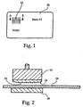
- Fig.1 shows a data carrier 24 with a lens structure 12 and various other information applied.
- Fig. 2 shows as a sectional view along the line AB of Fig. 1 a device for producing an embossed structure on a data carrier 24.
- the device comprises an embossing die 10 with unvergargender base structure 12 and an abutment 26.
- the punch 10 is pressed from above onto the disk 24 and optionally heated, so that the negative relief 12 in the Disk 24 abpresses.
- the stamp 10 is chamfered in a circumferential edge region 14.
- the material is better distributed by the chamfer 14, so that there is no beading on the peripheral edge of the die on the disk surface and corresponding deformations or warping of the disk can be avoided.
- the chamfer 14 extends around the entire peripheral edge of the embossing die 10 and thus forms a circumferential phase 14. This ensures a uniform distribution of the displaced material on the surface of the treated data carrier.
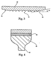
- Fig. 3 shows in an enlarged sectional view of the lower part of the die 10 of Fig.1 which is provided with a lens structure 12 on its surface. This surface is indicated by an imaginary line 18.
- This bevel includes the angle 16 with the line 18 of the imaginary surface.
- This chamfer reduces the pressure on the data carrier 24 in the edge region of the embossing die 10. As a result, warping, especially on the back of the data carrier 24, already avoided during the embossing process. Immediately after the embossing process, a practically undeformed or undulating data carrier 24 can be removed without further necessary treatment steps with respect to the warping.
- embossing forces of the order of 10 KN / cm 2 are advantageous.
- the formed by the stamp beads of the lenses spring back when removing the punch from the surface. This leads to a reduction in the accuracy of the formed lens geometry and accordingly to optical distortions when viewing a tilted image through this lens structure.
- By high frequencies with a small stroke of the oscillating die 10 can be reduced or eliminated with the ultrasound technique of this spring back, so that the formed lens structures have a very accurate, desired geometry.
- Fig. 5 it is provided to carry out a rebound step only locally in a region of the data carrier 24 after the embossing process, in which an embossing step was previously carried out.
- the data carrier 24 bears against a stop 30 and a bending punch 32 presses in the direction of the arrow 36 onto the data carrier 24 in a local, predetermined region in which a lens structure 34 has been previously impressed.
- stop 30 and punch 32 other suitable configurations than those in Fig. 5 exemplified possible.
- the re-bending step is preferably carried out during the cooling phase of the data carrier 24 after an embossing step.
Abstract
Description
Die Erfindung betrifft eine Vorrichtung zur Herstellung einer Oberflächenstruktur gemäß dem Oberbegriff von Anspruch 1.The invention relates to a device for producing a surface structure according to the preamble of claim 1.
Datenträger, wie z. B. Ausweiskarten, Bank- oder Kreditkarten werden in den verschiedensten Bereichen des täglichen Lebens eingesetzt. Beispielsweise dienen sie der Identifizierung des Inhabers oder der Durchführung bargeldloser Transaktionen. Es ist deshalb von größter Bedeutung, derartige Datenträger mit besonderen Sicherheitsmerkmalen zu versehen, so daß eine Fälschung derartiger Datenträger in größtmöglichem Maße erschwert und eine Verfälschung einfach erkannt wird.Disk, such. ID cards, bank cards or credit cards are used in various areas of everyday life. For example, they serve to identify the holder or to carry out cashless transactions. It is therefore of utmost importance to provide such data carriers with special security features, so that a forgery of such data carriers to the greatest extent difficult and falsification is easily detected.
Im Zusammenhang mit optischen Speichersystemen beschreibt die
Aus der
Dieses Kippbild besitzt eine Reihe von sicherheitstechnisch relevanten Vorteilen. So ist es beispielsweise weder mit fotografischen noch mit kopiertechnischen Mitteln reproduzierbar, da unter einem Aufnahmewinkel nie gleichzeitig alle Kippbild-Informationen vorliegen. Der gefälschte Datenträger zeigt somit lediglich eine der Informationen und diese unter allen Betrachtungswinkeln. Der Kippbildeffekt ist verschwunden. Zudem bietet die Laserbeschriftung einen zusätzlichen Fälschungsschutz. Denn bei der Laserbeschriftung werden im Inneren des Datenträgermaterials sichtbare Veränderungen hervorgerufen, die weder chemisch noch mechanisch ohne vollständige Zerstörung des Datenträgers entfernt oder geändert werden können.This tilting image has a number of safety-relevant advantages. Thus, for example, it can not be reproduced either with photographic or with copying technology, since at a recording angle, there is never at the same time all image information available. The fake data carrier thus shows only one of the information and this under all viewing angles. The tilt image effect has disappeared. In addition, the laser marking offers additional protection against counterfeiting. For in laser inscription visible changes are caused inside the data carrier material that can neither be removed chemically nor mechanically without complete destruction of the data carrier or changed.
Dieses Sicherheitsmerkmal bietet auch bezüglich der wirtschaftlichen Herstellung von Datenträgern einige Vorteile. Denn die Beschriftung des Linsenrasterbereichs erfolgt erst nach der Fertigstellung des Datenträgers, so daß hierbei eventuell anfallender Ausschuß nicht beschriftet und daher komplizierte Abläufe für ein nachträgliches Herstellen eines neuen Datenträgers mit dem gleichen Datensatz vermieden werden. Dies gilt insbesondere für den Fäll, daß die Kippbildinformation benutzerbezogen ausgeführt ist.This security feature also offers some advantages in terms of economical production of data carriers. Because the labeling of the lenticular array is carried out only after the completion of the disk, so that any resulting Committee not labeled and therefore complicated processes for subsequent production of a new disk with the same record can be avoided. This is especially true for the case that the tilt image information is executed user-related.
Die Herstellung der Linsenstruktur erfolgte bisher entweder während der Herstellung des Datenträgers oder nach seiner Fertigstellung durch Einprägen mit einem Prägestempel. Durch die Erhitzung des Datenträgermaterials und den hierauf ausgeübten Druck kommt es allerdings leicht zu irreparablen Verzügen und zu störenden Durchprägungen auf die Datenträgerrückseite, die häufig als Druckfläche benutzt wird.The manufacture of the lens structure was previously either during the production of the data carrier or after its completion by impressing with an embossing die. Due to the heating of the data carrier material and the pressure exerted thereon, however, irreparable distortion and disturbing indentations on the back of the data carrier, which is frequently used as a printing surface, can easily occur.
Um diesen Nachteil zu beseitigen, wurde in der
Der vorliegenden Erfindung liegt daher die Aufgabe zugrunde, eine einfachere Vorrichtung zur Herstellung von Datenträgern mit einer Oberflächenstruktur vorzuschlagen, die aber dennoch Verzüge des Datenträgers vermeidet.The present invention is therefore based on the object to propose a simpler apparatus for the production of data carriers with a surface structure, but nevertheless avoids distortion of the data carrier.
Diese Aufgabe wird durch die in den unabhängigen Ansprüchen definierten Merkmale gelöst. Vorteilhafte Weiterbildung und Ausführungsformen ergeben sich aus den abhängigen Ansprüchen.This object is achieved by the features defined in the independent claims. Advantageous development and embodiments emerge from the dependent claims.
Die Erfindung beruht auf dem Grundgedanken, durch entsprechendes Ausbilden des Randbereiches von Prägewerkzeugen die Auswirkungen des Prägevorgangs für einen Datenträger auf die Ausbildung einer Prägestruktur zu begrenzen und sekundäre Effekte zu minimieren bzw. zu eliminieren.The invention is based on the basic idea to limit the effects of the embossing process for a data carrier on the formation of an embossed structure by appropriate formation of the edge region of embossing tools and to minimize or eliminate secondary effects.
Dies hat den Vorteil kurzer Taktzeiten, bei gleichzeitiger Vermeidung von Verzügen auf der Rückseite und von Verwölbungen im Übergangsbereich zwischen Oberflächenstruktur und Karte, so daß ein kontinuierlicher Übergang entsteht.This has the advantage of short cycle times, while avoiding distortion on the back and warping in the transition region between the surface structure and the card, so that a continuous transition arises.
In einer bevorzugten Ausführungsform liegt die Oberflächenstruktur innerhalb der Kartenoberfläche und der Prägestempel ist rundumlaufend abgeschrägt, wobei der Winkel der Abschrägung vorzugsweise 10 bis 30 Grad beträgt.In a preferred embodiment, the surface structure is within the card surface and the die is circumferentially bevelled, the bevel angle preferably being 10 to 30 degrees.
Alternativ kann auch das Gegenlager rundumlaufend abgeschrägt sein.Alternatively, the counter bearing can be chamfered all around.
Weitere Vorteile und vorteilhafte Ausgestaltung der vorliegenden Erfindung ergeben sich aus der nachfolgenden Beschreibung bevorzugter Ausführungsbeispiele anhand der Figuren.Further advantages and advantageous embodiment of the present invention will become apparent from the following description of preferred embodiments with reference to FIGS.
Es zeigen:
- Fig. 1
- eine Aufsicht eines Datenträgers,
- Fig. 2
- eine Schnittansicht entlang Linie A-B von
Fig. 1 einer Vorrichtung mit Prägestempel und Gegenlager, - Fig. 3
- eine Schnittansicht einer bevorzugten Ausführungsform eines erfindungsgemäßen Prägestempels,
- Fig. 4
- eine Schnittansicht eines Prägestempels mit Ultraschall-Sonotrode und
- Fig. 5
- einen Datenträger während eines erfindungsgemäßen lokalen Rückbiegeschrittes.
- Fig. 1
- a top view of a data carrier,
- Fig. 2
- a sectional view taken along line AB of
Fig. 1 a device with die and counter bearing, - Fig. 3
- a sectional view of a preferred embodiment of an embossing stamp according to the invention,
- Fig. 4
- a sectional view of a stamping die with ultrasonic sonotrode and
- Fig. 5
- a data carrier during a local Rückbiegeschrittes invention.
Beim Aufsetzen dieses Prägestempels 10 auf eine zu behandelnde Oberfläche des Datenträgers 24 wird durch die Abschrägung 14 das Material besser verteilt, so daß es zu keiner Wulstbildung am umlaufenden Rand des Prägestempels auf der Datenträgeroberfläche kommt und entsprechende Verformungen bzw. Verwölbungen des Datenträgers vermieden werden. Die Abschrägung 14 verläuft um den gesamten umlaufenden Rand des Prägestempels 10 und bildet so eine umlaufende Phase 14. Dies gewährleistet eine gleichmäßige Verteilung des verdrängten Materials an der Oberfläche des behandelten Datenträgers.When placing this
Im Randbereich ist der erfindungsgemäße Prägestempel 10 mit einer Abschrägung 14 ausgebildet. Diese Abschrägung schließt mit der Linie 18 der gedachten Oberfläche den Winkel 16 ein.In the edge region of the embossing die 10 according to the invention is formed with a
Diese Abschrägung reduziert den Druck auf den Datenträger 24 im Randbereich des Prägestempels 10. Dadurch werden Verwölbungen, insbesondere auf der Rückseite des Datenträgers 24, bereits beim Prägevorgang vermieden. Unmittelbar nach dem Prägevorgang kann ein praktisch unverbogener bzw. unverwölbter Datenträger 24 ohne weitere notwendige Behandlungsschritte bezüglich der Verwölbung entnommen werden. -This chamfer reduces the pressure on the
Hierbei sind insbesondere Prägekräfte in der Größenordnung von 10 KN/cm2 vorteilhaft.In particular, embossing forces of the order of 10 KN / cm 2 are advantageous.
- 1. Es entsteht an einem Berührungspunkt zwischen Datenträgeroberfläche und Spitzen des Stempels 10 eine Mikroreibung, die zu einer entsprechenden Erwärmung des Kunststoffes führt.
- 2. Es wird die Struktur des Stempels 10 durch die oszillierende Bewegung des Prägestempels 10 an
der Sonotrode 20 aufgrund desvon dem Piezokristall 22 erzeugten Ultraschalls sozusagen eingetrieben. Dies erzeugt zusätzlich hohe Druckspitzen an den Berührungspunkten zwischen Datenträger und Prägestempel 10.
- 1. At a point of contact between the data carrier surface and the tips of the
punch 10, a micro friction occurs, which leads to a corresponding heating of the plastic. - 2. The structure of the
punch 10 is so to speak driven by the oscillating movement of the stamping die 10 on thesonotrode 20 due to the ultrasound generated by thepiezoelectric crystal 22. This additionally generates high pressure peaks at the points of contact between the data carrier and die 10.
Beim Heißprägen ohne Ultraschall wird häufig folgender Effekt beobachtet:Hot stamping without ultrasound often has the following effect:
Die durch den Stempel ausgebildeten Wülste der Linsen federn beim Abnehmen des Stempels von der Oberfläche zurück. Dies führt zu einer Reduzierung der Genauigkeit der ausgebildeten Linsengeometrie und entsprechend zu optischen Verzerrungen bei Betrachtung eines Kippbildes durch diese Linsenstruktur. Durch hohe Frequenzen mit geringem Hub des oszillierenden Prägestempels 10 kann mit der Ultraschalltechnik dieses Zurückfedern vermindert bzw. beseitigt werden, so daß die ausgebildeten Linsenstrukturen eine sehr genaue, gewünschte Geometrie aufweisen.The formed by the stamp beads of the lenses spring back when removing the punch from the surface. This leads to a reduction in the accuracy of the formed lens geometry and accordingly to optical distortions when viewing a tilted image through this lens structure. By high frequencies with a small stroke of the oscillating die 10 can be reduced or eliminated with the ultrasound technique of this spring back, so that the formed lens structures have a very accurate, desired geometry.
Wie in
Selbstverständlich sind bezüglich der Ausbildung von Anschlag 30 und Biegestempel 32 auch andere geeignete Konfigurationen als die in
Der Rückbiegeschritt wird bevorzugt während der Abkühlphase des Datenträgers 24 nach einem Prägeschritt ausgeführt.The re-bending step is preferably carried out during the cooling phase of the
Zur nachträglichen Beseitigung einer lokalen Verwölbung wird ferner vorgeschlagen, den verwölbten Bereich 34 gleichmäßig zu erwärmen und wieder abkühlen zu lassen. Durch Erwärmen des Materials, z. B. über Infrarotlicht, bis zur Plastizitätsgrenze wird eine Tendenz des Materials des Datenträgers 24 erzeugt, bei der sich dieses Material ausdehnen möchte. Da der Umgebungsbereich des verwölbten Bereichs 34 jedoch nicht erwärmt wird, ist eine Ausdehnung nur in Form einer dicken Änderung möglich. Beim Abkühlen zieht sich das Material gleichmäßig zusammen und glättet dabei lokale Verwölbungen.For the subsequent elimination of a local warping, it is also proposed to heat the
In besonders bevorzugter Weise, werden die eben geschilderten Temperaturbehandlungsschritte mit den zuvor in Zusammenhang mit
Claims (9)
- An apparatus for producing a surface structure in the form of a lens structure (12) on a data carrier with an embossing die (10) and a support (26), characterized in that the embossing die (10) and/or the support (26) is beveled in the total all-around edge area (14).
- The apparatus according to claim 1, characterized in that the beveled edge area (14) extends in such a way that the thickness of the embossing die (10) and/or of the support (26) tapers outwardly.
- The apparatus according to at least one of claims 1 to 2, characterized in that the embossing die (10) and/or the support (26) are covered with a protective layer, in particular chromium-plated.
- The apparatus according to at least one of claims 1 to 3, characterized in that the embossing die (10) has a sonotrode (20) connected to an ultrasound source (22).
- The apparatus according to claim 4, characterized in that the ultrasound source is a piezoelectric crystal (22).
- A data carrier having a surface structure (12) formed in at least a predetermined area of the surface thereof, characterized in that the surface structure (12) has in the total all-around edge area a beveled portion which continuously connects the surface without the surface structure to the surface with the surface structure.
- The data carrier according to claim 6, characterized in that the surface structure (12) is an embossed structure, in particular a lens structure, in particular a cylinder lens structure and/or spherical lens structure.
- The data carrier according to claim 6 or 7, characterized in that the beveled portion has an angle of 1 to 30°, in particular 10°, with respect to the surrounding surface of the data carrier (24).
- A method for producing a surface structure in the form of a lens structure (12) on a data carrier, the surface structure being embossed with an embossing die (10) and a support (26) in an embossing step, characterized in that the embossing die (10) and/or the support (26) is beveled in the total all-around edge area (14).
Priority Applications (1)
| Application Number | Priority Date | Filing Date | Title |
|---|---|---|---|
| EP05019761A EP1605398B1 (en) | 1996-11-14 | 1997-11-05 | Method for producing a data carrier |
Applications Claiming Priority (2)
| Application Number | Priority Date | Filing Date | Title |
|---|---|---|---|
| DE19647154 | 1996-11-14 | ||
| DE19647154A DE19647154A1 (en) | 1996-11-14 | 1996-11-14 | Device for the production of surface structures |
Related Child Applications (2)
| Application Number | Title | Priority Date | Filing Date |
|---|---|---|---|
| EP05019761A Division-Into EP1605398B1 (en) | 1996-11-14 | 1997-11-05 | Method for producing a data carrier |
| EP05019761A Division EP1605398B1 (en) | 1996-11-14 | 1997-11-05 | Method for producing a data carrier |
Publications (5)
| Publication Number | Publication Date |
|---|---|
| EP0843281A2 EP0843281A2 (en) | 1998-05-20 |
| EP0843281A3 EP0843281A3 (en) | 2000-12-06 |
| EP0843281B1 EP0843281B1 (en) | 2006-04-19 |
| EP0843281B9 EP0843281B9 (en) | 2007-02-21 |
| EP0843281B2 true EP0843281B2 (en) | 2015-03-11 |
Family
ID=7811710
Family Applications (2)
| Application Number | Title | Priority Date | Filing Date |
|---|---|---|---|
| EP97119325.5A Expired - Lifetime EP0843281B2 (en) | 1996-11-14 | 1997-11-05 | Device for producing surface structures |
| EP05019761A Expired - Lifetime EP1605398B1 (en) | 1996-11-14 | 1997-11-05 | Method for producing a data carrier |
Family Applications After (1)
| Application Number | Title | Priority Date | Filing Date |
|---|---|---|---|
| EP05019761A Expired - Lifetime EP1605398B1 (en) | 1996-11-14 | 1997-11-05 | Method for producing a data carrier |
Country Status (3)
| Country | Link |
|---|---|
| EP (2) | EP0843281B2 (en) |
| AT (2) | ATE357029T1 (en) |
| DE (3) | DE19647154A1 (en) |
Families Citing this family (6)
| Publication number | Priority date | Publication date | Assignee | Title |
|---|---|---|---|---|
| DE102004041434B4 (en) | 2004-08-27 | 2013-10-10 | Credit Card Supplies | Method for producing a embossing plate for a hot-cold laminating press with three-dimensional structures |
| DE202004021955U1 (en) | 2004-08-27 | 2013-07-16 | Credit Card Supplies | Embossing plate with three-dimensional structure for the production of documents by means of hot-cold laminating press |
| DE102008008044B4 (en) | 2008-02-05 | 2022-09-22 | Bundesdruckerei Gmbh | Process for embossing surface structures in a substrate for the production of a card-shaped data carrier |
| DE102008031653A1 (en) | 2008-07-03 | 2010-01-14 | Bundesdruckerei Gmbh | Method and device for introducing a security feature into a value or security document |
| DE102008031656B4 (en) * | 2008-07-03 | 2016-07-28 | Bundesdruckerei Gmbh | Polymer layer composite for a security and / or value document and method and apparatus for its production |
| DE102017130298A1 (en) | 2017-12-18 | 2019-06-19 | Bundesdruckerei Gmbh | Apparatus and method for measuring image data |
Citations (2)
| Publication number | Priority date | Publication date | Assignee | Title |
|---|---|---|---|---|
| EP0219012A2 (en) † | 1985-10-15 | 1987-04-22 | GAO Gesellschaft für Automation und Organisation mbH | Data carrier with an optical authenticity feature, and method of making and checking the data carrier |
| WO1996015912A2 (en) † | 1994-11-18 | 1996-05-30 | Giesecke & Devrient Gmbh | Data carrier production process |
Family Cites Families (2)
| Publication number | Priority date | Publication date | Assignee | Title |
|---|---|---|---|---|
| JPS5425380B2 (en) * | 1972-02-15 | 1979-08-28 | ||
| DE4441198A1 (en) * | 1994-11-18 | 1996-05-23 | Giesecke & Devrient Gmbh | Data carrier and process equipment mfr. |
-
1996
- 1996-11-14 DE DE19647154A patent/DE19647154A1/en not_active Withdrawn
-
1997
- 1997-11-05 EP EP97119325.5A patent/EP0843281B2/en not_active Expired - Lifetime
- 1997-11-05 DE DE59712828T patent/DE59712828D1/en not_active Expired - Lifetime
- 1997-11-05 AT AT05019761T patent/ATE357029T1/en not_active IP Right Cessation
- 1997-11-05 EP EP05019761A patent/EP1605398B1/en not_active Expired - Lifetime
- 1997-11-05 DE DE59712620T patent/DE59712620D1/en not_active Expired - Lifetime
- 1997-11-05 AT AT97119325T patent/ATE323914T1/en not_active IP Right Cessation
Patent Citations (2)
| Publication number | Priority date | Publication date | Assignee | Title |
|---|---|---|---|---|
| EP0219012A2 (en) † | 1985-10-15 | 1987-04-22 | GAO Gesellschaft für Automation und Organisation mbH | Data carrier with an optical authenticity feature, and method of making and checking the data carrier |
| WO1996015912A2 (en) † | 1994-11-18 | 1996-05-30 | Giesecke & Devrient Gmbh | Data carrier production process |
Also Published As
| Publication number | Publication date |
|---|---|
| EP1605398B1 (en) | 2007-03-14 |
| ATE357029T1 (en) | 2007-04-15 |
| EP0843281B1 (en) | 2006-04-19 |
| DE59712620D1 (en) | 2006-05-24 |
| EP0843281B9 (en) | 2007-02-21 |
| DE59712828D1 (en) | 2007-04-26 |
| ATE323914T1 (en) | 2006-05-15 |
| EP1605398A2 (en) | 2005-12-14 |
| EP0843281A3 (en) | 2000-12-06 |
| DE19647154A1 (en) | 1998-05-28 |
| EP1605398A3 (en) | 2005-12-21 |
| EP0843281A2 (en) | 1998-05-20 |
Similar Documents
| Publication | Publication Date | Title |
|---|---|---|
| EP0330738B1 (en) | Document | |
| EP0537439B1 (en) | Security element | |
| EP2265999B1 (en) | Holographic security element and method for producing same | |
| EP1501045B1 (en) | Optically variable element with non-holographic data and its production method | |
| EP1629994B1 (en) | Method of manufacturing an embossed metal plate with a three dimensional structure for producing documents using a hot-cold laminating press | |
| EP2002310B1 (en) | Method of manufacturing a multi-layer body with a volume hologram, and security element | |
| DE102013200980B4 (en) | Process for subsequent holographic labeling and device for subsequent holographic labeling | |
| EP2164705B1 (en) | A method for manufacturing a seamless continuous material for security elements, a seamless continuous material for security elements and methods for manufacturing impression or embossing cylinders | |
| WO1994018609A1 (en) | Process, printing material and device for reproducing holographic fine structures and other diffraction grids on print products | |
| EP2027562A2 (en) | Method for production of documents with a hologram and a document with a hologram | |
| DE102019110833A1 (en) | Method and device for producing a hologram, hologram and lighting device for a vehicle | |
| EP0843281B2 (en) | Device for producing surface structures | |
| EP3828002B1 (en) | Value document | |
| WO2005029135A2 (en) | Method and film system for producing a personalised, optically variable element | |
| EP0715232A2 (en) | Master hologram for the fabrication of copy-protected holograms | |
| WO2014041079A1 (en) | Master for producing a volume reflection hologram having improved marker formation | |
| EP0683903A1 (en) | Process, printing material and device for reproducing holographic fine structures and other diffraction grids on print products | |
| EP2054845B1 (en) | Card-like data storage medium, and method for recording information on such a data storage medium | |
| WO2024033357A1 (en) | Device for replicating a plurality of holograms according to a type-case principle | |
| WO2024033354A1 (en) | Method for replicating a plurality of holograms by means of a typecase principle | |
| DE102022002471A1 (en) | Method for producing a security feature, security feature for a data carrier, data carrier and laminating sheet | |
| DE202004021955U1 (en) | Embossing plate with three-dimensional structure for the production of documents by means of hot-cold laminating press | |
| WO2019162143A1 (en) | Device and method for recording information in a data carrier | |
| DE10250476A1 (en) | The laser assisted security marking assembly, for individual markings on a substrate, has a laser beam directed at the replicating surface to form shaping zones to be imposed on the substrate by pressure |
Legal Events
| Date | Code | Title | Description |
|---|---|---|---|
| PUAI | Public reference made under article 153(3) epc to a published international application that has entered the european phase |
Free format text: ORIGINAL CODE: 0009012 |
|
| AK | Designated contracting states |
Kind code of ref document: A2 Designated state(s): AT BE CH DE DK ES FI FR GB GR IE IT LI LU MC NL PT SE |
|
| AX | Request for extension of the european patent |
Free format text: AL;LT;LV;MK;RO;SI |
|
| PUAL | Search report despatched |
Free format text: ORIGINAL CODE: 0009013 |
|
| AK | Designated contracting states |
Kind code of ref document: A3 Designated state(s): AT BE CH DE DK ES FI FR GB GR IE IT LI LU MC NL PT SE |
|
| AX | Request for extension of the european patent |
Free format text: AL;LT;LV;MK;RO;SI |
|
| 17P | Request for examination filed |
Effective date: 20010606 |
|
| AKX | Designation fees paid |
Free format text: AT BE CH DE DK ES FI FR GB GR IE IT LI LU MC NL PT SE |
|
| 17Q | First examination report despatched |
Effective date: 20031103 |
|
| GRAP | Despatch of communication of intention to grant a patent |
Free format text: ORIGINAL CODE: EPIDOSNIGR1 |
|
| GRAS | Grant fee paid |
Free format text: ORIGINAL CODE: EPIDOSNIGR3 |
|
| GRAA | (expected) grant |
Free format text: ORIGINAL CODE: 0009210 |
|
| AK | Designated contracting states |
Kind code of ref document: B1 Designated state(s): AT BE CH DE DK ES FI FR GB GR IE IT LI LU MC NL PT SE |
|
| PG25 | Lapsed in a contracting state [announced via postgrant information from national office to epo] |
Ref country code: NL Free format text: LAPSE BECAUSE OF FAILURE TO SUBMIT A TRANSLATION OF THE DESCRIPTION OR TO PAY THE FEE WITHIN THE PRESCRIBED TIME-LIMIT Effective date: 20060419 Ref country code: IT Free format text: LAPSE BECAUSE OF FAILURE TO SUBMIT A TRANSLATION OF THE DESCRIPTION OR TO PAY THE FEE WITHIN THE PRE;WARNING: LAPSES OF ITALIAN PATENTS WITH EFFECTIVE DATE BEFORE 2007 MAY HAVE OCCURRED AT ANY TIME BEFORE 2007. THE CORRECT EFFECTIVE DATE MAY BE DIFFERENT FROM THE ONE RECORDED.SCRIBED TIME-LIMIT Effective date: 20060419 Ref country code: IE Free format text: LAPSE BECAUSE OF FAILURE TO SUBMIT A TRANSLATION OF THE DESCRIPTION OR TO PAY THE FEE WITHIN THE PRESCRIBED TIME-LIMIT Effective date: 20060419 Ref country code: GB Free format text: LAPSE BECAUSE OF FAILURE TO SUBMIT A TRANSLATION OF THE DESCRIPTION OR TO PAY THE FEE WITHIN THE PRESCRIBED TIME-LIMIT Effective date: 20060419 |
|
| REG | Reference to a national code |
Ref country code: GB Ref legal event code: FG4D Free format text: NOT ENGLISH |
|
| REG | Reference to a national code |
Ref country code: CH Ref legal event code: NV Representative=s name: PATENTANWAELTE SCHAAD, BALASS, MENZL & PARTNER AG |
|
| REF | Corresponds to: |
Ref document number: 59712620 Country of ref document: DE Date of ref document: 20060524 Kind code of ref document: P |
|
| REG | Reference to a national code |
Ref country code: IE Ref legal event code: FG4D Free format text: LANGUAGE OF EP DOCUMENT: GERMAN |
|
| PG25 | Lapsed in a contracting state [announced via postgrant information from national office to epo] |
Ref country code: SE Free format text: LAPSE BECAUSE OF FAILURE TO SUBMIT A TRANSLATION OF THE DESCRIPTION OR TO PAY THE FEE WITHIN THE PRESCRIBED TIME-LIMIT Effective date: 20060719 Ref country code: DK Free format text: LAPSE BECAUSE OF FAILURE TO SUBMIT A TRANSLATION OF THE DESCRIPTION OR TO PAY THE FEE WITHIN THE PRESCRIBED TIME-LIMIT Effective date: 20060719 |
|
| PG25 | Lapsed in a contracting state [announced via postgrant information from national office to epo] |
Ref country code: ES Free format text: LAPSE BECAUSE OF FAILURE TO SUBMIT A TRANSLATION OF THE DESCRIPTION OR TO PAY THE FEE WITHIN THE PRESCRIBED TIME-LIMIT Effective date: 20060730 |
|
| PG25 | Lapsed in a contracting state [announced via postgrant information from national office to epo] |
Ref country code: PT Free format text: LAPSE BECAUSE OF FAILURE TO SUBMIT A TRANSLATION OF THE DESCRIPTION OR TO PAY THE FEE WITHIN THE PRESCRIBED TIME-LIMIT Effective date: 20060919 |
|
| ET | Fr: translation filed | ||
| NLV1 | Nl: lapsed or annulled due to failure to fulfill the requirements of art. 29p and 29m of the patents act | ||
| GBV | Gb: ep patent (uk) treated as always having been void in accordance with gb section 77(7)/1977 [no translation filed] |
Effective date: 20060419 |
|
| REG | Reference to a national code |
Ref country code: IE Ref legal event code: FD4D |
|
| PG25 | Lapsed in a contracting state [announced via postgrant information from national office to epo] |
Ref country code: MC Free format text: LAPSE BECAUSE OF NON-PAYMENT OF DUE FEES Effective date: 20061130 Ref country code: BE Free format text: LAPSE BECAUSE OF NON-PAYMENT OF DUE FEES Effective date: 20061130 |
|
| PLAX | Notice of opposition and request to file observation + time limit sent |
Free format text: ORIGINAL CODE: EPIDOSNOBS2 |
|
| PLBI | Opposition filed |
Free format text: ORIGINAL CODE: 0009260 |
|
| PLBB | Reply of patent proprietor to notice(s) of opposition received |
Free format text: ORIGINAL CODE: EPIDOSNOBS3 |
|
| 26 | Opposition filed |
Opponent name: BUNDESDRUCKEREI GMBH Effective date: 20070119 |
|
| BERE | Be: lapsed |
Owner name: GIESECKE & DEVRIENT G.M.B.H. Effective date: 20061130 |
|
| PG25 | Lapsed in a contracting state [announced via postgrant information from national office to epo] |
Ref country code: AT Free format text: LAPSE BECAUSE OF NON-PAYMENT OF DUE FEES Effective date: 20061105 |
|
| PG25 | Lapsed in a contracting state [announced via postgrant information from national office to epo] |
Ref country code: GR Free format text: LAPSE BECAUSE OF FAILURE TO SUBMIT A TRANSLATION OF THE DESCRIPTION OR TO PAY THE FEE WITHIN THE PRESCRIBED TIME-LIMIT Effective date: 20060720 |
|
| PG25 | Lapsed in a contracting state [announced via postgrant information from national office to epo] |
Ref country code: LU Free format text: LAPSE BECAUSE OF NON-PAYMENT OF DUE FEES Effective date: 20061105 |
|
| APBM | Appeal reference recorded |
Free format text: ORIGINAL CODE: EPIDOSNREFNO |
|
| APBP | Date of receipt of notice of appeal recorded |
Free format text: ORIGINAL CODE: EPIDOSNNOA2O |
|
| APAH | Appeal reference modified |
Free format text: ORIGINAL CODE: EPIDOSCREFNO |
|
| APBQ | Date of receipt of statement of grounds of appeal recorded |
Free format text: ORIGINAL CODE: EPIDOSNNOA3O |
|
| PLAB | Opposition data, opponent's data or that of the opponent's representative modified |
Free format text: ORIGINAL CODE: 0009299OPPO |
|
| APBU | Appeal procedure closed |
Free format text: ORIGINAL CODE: EPIDOSNNOA9O |
|
| R26 | Opposition filed (corrected) |
Opponent name: BUNDESDRUCKEREI GMBH Effective date: 20070119 |
|
| REG | Reference to a national code |
Ref country code: DE Ref legal event code: R082 Ref document number: 59712620 Country of ref document: DE |
|
| APAN | Information on closure of appeal procedure modified |
Free format text: ORIGINAL CODE: EPIDOSCNOA9O |
|
| PGFP | Annual fee paid to national office [announced via postgrant information from national office to epo] |
Ref country code: DE Payment date: 20141130 Year of fee payment: 18 Ref country code: FI Payment date: 20141119 Year of fee payment: 18 Ref country code: CH Payment date: 20141120 Year of fee payment: 18 |
|
| PUAH | Patent maintained in amended form |
Free format text: ORIGINAL CODE: 0009272 |
|
| STAA | Information on the status of an ep patent application or granted ep patent |
Free format text: STATUS: PATENT MAINTAINED AS AMENDED |
|
| PGFP | Annual fee paid to national office [announced via postgrant information from national office to epo] |
Ref country code: FR Payment date: 20141118 Year of fee payment: 18 |
|
| 27A | Patent maintained in amended form |
Effective date: 20150311 |
|
| AK | Designated contracting states |
Kind code of ref document: B2 Designated state(s): AT BE CH DE DK ES FI FR GB GR IE IT LI LU MC NL PT SE |
|
| REG | Reference to a national code |
Ref country code: DE Ref legal event code: R102 Ref document number: 59712620 Country of ref document: DE |
|
| REG | Reference to a national code |
Ref country code: CH Ref legal event code: AELC |
|
| REG | Reference to a national code |
Ref country code: DE Ref legal event code: R102 Ref document number: 59712620 Country of ref document: DE Effective date: 20150311 |
|
| PG25 | Lapsed in a contracting state [announced via postgrant information from national office to epo] |
Ref country code: FI Free format text: LAPSE BECAUSE OF FAILURE TO SUBMIT A TRANSLATION OF THE DESCRIPTION OR TO PAY THE FEE WITHIN THE PRESCRIBED TIME-LIMIT Effective date: 20150311 |
|
| REG | Reference to a national code |
Ref country code: DE Ref legal event code: R119 Ref document number: 59712620 Country of ref document: DE |
|
| REG | Reference to a national code |
Ref country code: CH Ref legal event code: PL |
|
| PG25 | Lapsed in a contracting state [announced via postgrant information from national office to epo] |
Ref country code: LI Free format text: LAPSE BECAUSE OF NON-PAYMENT OF DUE FEES Effective date: 20151130 Ref country code: CH Free format text: LAPSE BECAUSE OF NON-PAYMENT OF DUE FEES Effective date: 20151130 |
|
| REG | Reference to a national code |
Ref country code: FR Ref legal event code: ST Effective date: 20160729 |
|
| PG25 | Lapsed in a contracting state [announced via postgrant information from national office to epo] |
Ref country code: DE Free format text: LAPSE BECAUSE OF NON-PAYMENT OF DUE FEES Effective date: 20160601 |
|
| PG25 | Lapsed in a contracting state [announced via postgrant information from national office to epo] |
Ref country code: FR Free format text: LAPSE BECAUSE OF NON-PAYMENT OF DUE FEES Effective date: 20151130 |