EP0843172A1 - Flow cell as well as device for generating evanescent stimulated radiation - Google Patents
Flow cell as well as device for generating evanescent stimulated radiation Download PDFInfo
- Publication number
- EP0843172A1 EP0843172A1 EP96810807A EP96810807A EP0843172A1 EP 0843172 A1 EP0843172 A1 EP 0843172A1 EP 96810807 A EP96810807 A EP 96810807A EP 96810807 A EP96810807 A EP 96810807A EP 0843172 A1 EP0843172 A1 EP 0843172A1
- Authority
- EP
- European Patent Office
- Prior art keywords
- flow cell
- radiation
- recess
- waveguide
- coupling
- Prior art date
- Legal status (The legal status is an assumption and is not a legal conclusion. Google has not performed a legal analysis and makes no representation as to the accuracy of the status listed.)
- Withdrawn
Links
Images


Classifications
-
- G—PHYSICS
- G01—MEASURING; TESTING
- G01N—INVESTIGATING OR ANALYSING MATERIALS BY DETERMINING THEIR CHEMICAL OR PHYSICAL PROPERTIES
- G01N21/00—Investigating or analysing materials by the use of optical means, i.e. using sub-millimetre waves, infrared, visible or ultraviolet light
- G01N21/62—Systems in which the material investigated is excited whereby it emits light or causes a change in wavelength of the incident light
- G01N21/63—Systems in which the material investigated is excited whereby it emits light or causes a change in wavelength of the incident light optically excited
- G01N21/64—Fluorescence; Phosphorescence
- G01N21/645—Specially adapted constructive features of fluorimeters
- G01N21/648—Specially adapted constructive features of fluorimeters using evanescent coupling or surface plasmon coupling for the excitation of fluorescence
-
- G—PHYSICS
- G01—MEASURING; TESTING
- G01N—INVESTIGATING OR ANALYSING MATERIALS BY DETERMINING THEIR CHEMICAL OR PHYSICAL PROPERTIES
- G01N21/00—Investigating or analysing materials by the use of optical means, i.e. using sub-millimetre waves, infrared, visible or ultraviolet light
- G01N21/01—Arrangements or apparatus for facilitating the optical investigation
- G01N21/03—Cuvette constructions
- G01N21/05—Flow-through cuvettes
-
- G—PHYSICS
- G01—MEASURING; TESTING
- G01N—INVESTIGATING OR ANALYSING MATERIALS BY DETERMINING THEIR CHEMICAL OR PHYSICAL PROPERTIES
- G01N21/00—Investigating or analysing materials by the use of optical means, i.e. using sub-millimetre waves, infrared, visible or ultraviolet light
- G01N21/75—Systems in which material is subjected to a chemical reaction, the progress or the result of the reaction being investigated
- G01N21/77—Systems in which material is subjected to a chemical reaction, the progress or the result of the reaction being investigated by observing the effect on a chemical indicator
- G01N21/7703—Systems in which material is subjected to a chemical reaction, the progress or the result of the reaction being investigated by observing the effect on a chemical indicator using reagent-clad optical fibres or optical waveguides
-
- G—PHYSICS
- G01—MEASURING; TESTING
- G01N—INVESTIGATING OR ANALYSING MATERIALS BY DETERMINING THEIR CHEMICAL OR PHYSICAL PROPERTIES
- G01N21/00—Investigating or analysing materials by the use of optical means, i.e. using sub-millimetre waves, infrared, visible or ultraviolet light
- G01N21/01—Arrangements or apparatus for facilitating the optical investigation
- G01N21/03—Cuvette constructions
- G01N2021/0346—Capillary cells; Microcells
Definitions
- the invention relates to a flow cell and a device for generating evanescently excited radiation with at least one coupling element and with a waveguide the sample substance can be applied, with the or each coupling element Excitation radiation can be coupled into the waveguide.
- the invention has for its object a flow cell and a device of the beginning mentioned type in such a way that routine handling, especially in Screening is easily possible.
- the flow cell also the or each decoupling element covered.
- the recess completely between the or each coupling element and the or each Coupling element is arranged so that both the or each coupling element as well the or each decoupling element is free of sample material. This has the advantage of both in the coupling as well as in the coupling of excitation radiation respectively Coupling conditions that remain evanescently excited by radiation and are unaffected by the sample material to rule.
- recesses are provided, which are longitudinal or transverse to the Direction of propagation of excitation radiation are arranged.
- absorbent material to provide a coupling prevent radiation components between the recesses.
- absorbent layer between the flow cell and the waveguide is applied.
- the Flow cell consists of a pliable material that has the at least one recess tightly seals when applied to the waveguide. This makes it like no other aids Seals possible, leak-free by placing a flow cell on the waveguide Guide sample material through the flow cell.
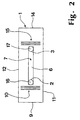
- Fig. 1 shows a perspective view of one made of a pliable material existing flow cell 1.
- the flow cell 1 shown in FIG. 1 is made of an elastic, flexible polymeric material made, at least in visible and near infrared Spectral range is transparent to electromagnetic radiation.
- a polydimethylsiloxane such as Sylgard 182 or Sylgard 184 (Dow Corning) or from the RTVE series (room temperature crosslinkable elastomers, Wacker Chemitronic).
- Flow cell 1 that can be produced is also a single use in addition to reuse economically reasonable.
- the flow cell 1 has an inlet channel 2 as the first sample channel and an outlet channel 3 as a second sample channel for the inlet or outlet of Sample liquid, these functions are interchangeable.
- the inlet duct 2 and the Outlet channel 3 extend between a top surface 4 and one in one of the top surface 4 opposite support surface 5 introduced recess 6 as a flow channel.
- the Recess 6 is open on its side facing the support surface 5 and extends between the inlet duct 2 and the outlet duct 3.
- the flow cell 1 is attached in a self-adhesive manner to a layer waveguide 7, for example made of TiO 2 or Ta 2 O 5 .
- a layer waveguide 7 for example made of TiO 2 or Ta 2 O 5 .
- the flow cell 1 is attached to the layer waveguide with an adhesive such as, for example, a transparent adhesive.
- the recess 6 is tightly closed, so that a liquid stream which contains a sample material to be examined can flow through the inlet channel 2, the recess 6 and the outlet channel 3. Since the material of the flow cell 1 is pliable, it flexibly adapts to the surface structure of the waveguide 7 and thus leads to a seal without the need for additional sealing elements.
- the relatively thin layer waveguide 7 is on a mechanically stable substrate 8 For example, applied from glass or a polycarbonate and firmly connected to this.
- the flow cell 1, the waveguide 7 and the substrate 8 is a cuboid body with flush-fitting lateral ones Boundary surfaces.
- Other geometries such as ellipsoids, regular or irregular polygons also provided with a trapezoidal cross-section.
- the layer waveguide 7 according to FIG. 1 is transverse to the orientation of the recess 6 between an end face 9 adjacent to the inlet duct 2 and the inlet duct 2
- Coupling grating 10 introduced as a dispersive coupling element, which is essentially between the two side surfaces 11, 12 running parallel to the recess 6 by the flow cell 1, the layer waveguide 7 and the substrate 8 analysis unit 13 extends.
- a decoupling grating 15 is introduced into the layer waveguide 7.
- a plurality of coupling-in gratings and / or coupling-out gratings are provided, which act as Coupling elements or coupling elements are used.
- Coupling elements or coupling elements are used.
- FIG. 2 shows a top view of the top surface 4 of the flow cell 1. From FIG. 2 it can be seen that the recess 6 each with an edge distance between the coupling grid 10 and the coupling-out grating 15 extends, so that both the coupling-in grating 10 and that Auskoppelgitter 15 free of one through the inlet channel 2, the recess 6 and Outlet channel 3 is flowing sample liquid.
- Both the inlet duct 2 and the outlet duct 3 have a round one or not polygonal cross section shown and open in an inlet opening 16 as the first Sample passage opening or an outlet opening 17 as the second Sample passage opening into the recess 6.
- the inlet opening 16 and the outlet opening 17 directly to the coupling grid 10 and the coupling grid 15 facing ends of the recess 6 arranged, the inlet channel 2 and the outlet channel 3 perpendicular to the recess 6 are introduced into the flow cell 1.
- the inlet channel 2 and the Outlet channel 3 is arranged at an oblique angle to the recess 6 to the flow resistance in the area of the inlet opening 16 and the outlet opening 17 with respect to a right-angled one Decrease arrangement.
- FIG. 3 shows a side view of the transparent flow cell 1 according to FIGS. 1 and 2. In this view clearly shows the right-angled alignment of the recess 6 with the inlet duct 2 and the outlet duct 3 can be seen.
- the depth of the recess 6 depends essentially of the flow properties of a sample liquid flowing through and the Diffusion properties of the molecules to be analyzed and is between about 1 ⁇ m and 1000 ⁇ m.
- FIG. 4 shows the flow cell 1 according to FIG. 3 in a view of the end face 9.
- the cross section The recess 6 shown in Fig. 4 is substantially square, but the Width, that is, the extent between the side surfaces 11, 12 depending on the Flow properties and / or optical properties of a sample liquid flowing through is between 10 ⁇ m and 40 mm.
- the transition from the flow cell 1 to the or each recess 6 is preferably through a tapering tongue piece pointing in the direction of the recess is designed that the change in the refractive index in the area of the evanescent field at the transition of material of the flow cell 1 to one contained in the or each recess 6 Sample liquid is carried out continuously without cracks. This is done, for example, by a ellipsoidal profile achieved in the area of the evanescent field.
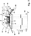
- FIG. 5 shows a perspective view of one in the area of the coupling grating 10 with excitation radiation 18 from a light source not shown in FIG. 5 for generating evanescently excited radiation with the flow cell 1, that on a substrate 8 applied waveguide 7 and with a through the inlet channel 2, the recess 6 and the sample liquid 19 flowing through the outlet channel 3.
- the sample liquid 19 contains for example symbolically represented luminescent molecules 20 to be analyzed.
- the excitation radiation 18 impinging on the coupling grating 10 is diffracted into the Layer waveguide 7 is coupled in and spreads as a guided wave in the direction of Auskoppelgitters 15 from.
- Recess 6 of the flow cell 1 are those contained in the sample liquid 19 luminescent molecules 20 due to the so-called evanescent portion of the excitation radiation 18, that is to say the material entering the waveguide 7, exponentially decaying radiation component, stimulated to luminescence.
- a detection unit is in the direction of propagation of the evanescently excited radiation 21 22 provided with which, for example, the intensity and its spectral distribution is analyzable.
- n the refractive index denoted by "n” and plotted on the ordinate 23 depending on the position on the abscissa 24 marked with "X” in Shown in the longitudinal direction in the penetration area of the evanescently excited radiation 21.
- the different areas in the longitudinal direction with respect to the flow cell 1 are shown with dashed lines Lines indicated on the abscissa 24.
- n 1.4
- the coupling of the output radiation 18 at a certain fixed angle enables that is independent of properties of the sample liquid 19.
- the arrangement shown in FIG. 5 results in a largely reflection-free one Coupling of the excitation radiation 18 into the waveguide 7 and only because of the relatively small jump in the refractive index when the evanescent portion of the Excitation radiation 18 in the sample liquid a high proportion of continued Output radiation 18, so that a high yield of evanescently excited radiation 21 is achieved by the relatively small refractive index jump at the coupling-out grating 15 facing end of the recess 6 is the disturbance of the evanescently excited Radiation 21 is also relatively low, so that when deflected by the coupling-out grating 15 an overall high signal yield is achieved. This makes it possible, too detect low concentrations of luminescent molecules 20 in the sample liquid 19.
- Fig. 6 shows a modification of a flow cell 1, the recess 6 of which the inlet opening 16 arranged between the coupling grid 10 and the coupling grid 15 adjacent end in the area between the coupling grid 15 and the Auskoppelgitter 15 extends adjacent end face 14 so that the recess 6 Coupling grid 15 covers.
- This configuration also results in a high one coupled intensity of excitation radiation 18, which is for the intensity of evanescent excited radiation 21 is of primary importance because of certain optical impairments in the area of the coupling-out grating 15 against interference in the area of the coupling-in grating 10 are of minor importance.
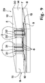
- FIG. 7 shows a simultaneous analysis unit 25, which is placed next to that on the substrate 8
- Layer waveguide 7 with coupling grating 10 and coupling grating 15 via a flow cell 26 has, each with three inlet channels 2, outlet channels 3 and between one Inlet channel 2 and an outlet channel 3 extending recesses 6 is provided.
- the layer waveguide 7 is structured in a strip shape such that a strip of the layer waveguide 7 is opposite a recess 6.
- each recess 6 an im Spectral range of excitation radiation 18 and evanescently excited radiation 21 absorbing damping layer 27 applied in order to over-coupling in particular evanescently excited radiation 21 from one recess 6 to the other two recesses 6 to prevent that would lead to a falsification of the measurement results.
- damping layer 27 which delimits each recess 6 on the longitudinal side, is thick Absorption of radiation components emerging from the area of the recesses 6. This makes it possible to have 6 different sample liquids 19 in the three recesses 6 to be investigated at the same time, since even when decoupled through the decoupling grid 15 evanescently excited radiation 21 spatially separated transversely to the direction of propagation are.
- FIG. 8 shows a plan view of the layer waveguide 7 of the simultaneous analysis unit 25 according to FIG Fig. 7.
- the between the coupling grid 10 and the coupling grid 15 essentially Attenuation layer 27 extending over the full width of the layer waveguide 7 is in each case parallel to the side surfaces 11, 12 aligned guide areas 28 with a rectangular Base area interrupted.
- the dimensions of the guide areas 28 correspond to Dimensions of the side facing the layer waveguide 7 according to the flow cell 26 according to Fig. 7 recesses 6.
- the damping layer 27 extends over the coupling grating 10 and that Coupling grid 15, the guide areas 28 also up to the coupling grid 10 and the decoupling grid 15 are extended.
- Fig. 9 shows a perspective view of another embodiment of a Simultaneous analysis unit 29, the structure of which of the simultaneous analysis unit 25 except for the Measures to prevent crosstalk. As a result, is only on the differences entered.
- the simultaneous analysis unit 29 has a flow cell 30, the one between the three inlet channels 2, outlet channels 3 and recesses 6 Damping inlet duct 31, a damping outlet duct 32 and in the illustration according to Fig. 9 covered by the recesses 6, open to the layer waveguide 7 out Has damping recess. 9 is in the Damping inlet channels 31, damping outlet channels 32 and the damping recess blackened damping agent, for example with a in the spectral range of Excitation radiation 18 and evanescently excited radiation 21 absorbing dye Liquid, filled.
- FIG. 10 shows a top view of the flow cell 30 in a layer waveguide 7 parallel, through the recesses 6 and the damping recesses 33 Cutting plane. From Fig. 10 it can be seen that in this embodiment, the Damping fluid filled damping recesses 33 in parallel and in between are arranged between two recesses 6, so that coupling of Excitation radiation 18 or evanescently excited radiation 21 from one Recess 6 to other recesses 6 due to the absorption or damping of the evanescent field through the introduced in the damping recesses 33 and the Layer waveguide 7 covering damping liquid is prevented.
- FIG. 11 shows a further simultaneous analysis unit 34 with a flow cell 35 in a top view a cut parallel to a layer waveguide 7.
- the flow cell 35 has a number of recesses 36, which are expediently equidistant between the Coupling grating 10 and the coupling grating 15 spaced apart and transverse to the direction of propagation of excitation radiation 18 coupled in via the coupling grating 10 are.
- there are also different recesses 36 introduced sample liquids 19 simultaneously via the evanescently excited Radiations 21 can be examined, with a defined superposition of the different ones Radiation components of the evanescently excited radiation 21 are brought about.
- FIG. 12 shows a further exemplary embodiment of a simultaneous analysis unit 37 in a section through a flow cell 38 in plan view of a parallel to the layer waveguide 7 Cut.
- the flow cell 38 has a number of recesses 39 which are parallel between the side surfaces 11, 12 are aligned, but in each case only over a fraction of the Distance between the coupling grid 10 and the coupling grid 15 extend.
- the length of each recess 39 is approximately one Fifth of the distance between the coupling grid 10 and the coupling grid 15.
- Die Recesses 39 are in three each transverse to the direction of propagation via the coupling grating 10 extending into the layer waveguide 7 coupled excitation radiation 18 Groups arranged, the recesses 39 of the coupling grating 10 and the Auskoppelgitter 15 adjacent edge groups in alignment and the recesses 39 of middle group are arranged transversely offset in gap areas of the marginal groups.
- the Simultaneous analysis unit 37 shown in FIG. 12 is particularly suitable for examination a large number of sample liquids 19 with already relatively short Interaction paths for the detection of sufficiently intensely evanescently excited Radiation 21.
- the flow cells shown in FIGS. 7 and 8, 9 and 10, 11 and 12 26, 30, 35, 38 are also preferably made of the material shown in FIG. 1 and there flow cell 1 discussed.
- the different geometries are a particularly simple way of taking an impression and arrangements of the recesses 6, 36, 39 can be produced, so that they are also proportionate complicated geometries or orientations for a single use are still economical.
- the low Manufacturing costs is also appropriate in the manufacture of a device for production evanescently excited radiation 21 with a flow cell 1, 26, 30, 35, 38 even before Use in some applications required marker molecules for the detection of specific Reactions or recognition elements for specific binding to be detected later Apply analytes to the waveguide 7. These marker molecules are through the overlying flow cell 1, 26, 30, 35, 38 protected.
- all flow cells 1, 26, 30, 35, 38 consist of an almost fluorescence-free one Material are made to overlap in the flow cells 1, 26, 30, 35, 38 evanescently excited fluorescence radiation with evanescently excited in sample liquid 19 for analysis Avoid radiation 21 to any significant extent. It is also appropriate that the Flow cells 1, 26, 30, 35, 38, for example on the end faces 9, 14, the side surfaces 11, 12 and the top surface 4 are radiation-absorbing in order to couple ambient radiation to prevent in the layer waveguide 7.
Landscapes
- Chemical & Material Sciences (AREA)
- Health & Medical Sciences (AREA)
- Physics & Mathematics (AREA)
- Immunology (AREA)
- Analytical Chemistry (AREA)
- Biochemistry (AREA)
- General Health & Medical Sciences (AREA)
- General Physics & Mathematics (AREA)
- Life Sciences & Earth Sciences (AREA)
- Pathology (AREA)
- Engineering & Computer Science (AREA)
- Chemical Kinetics & Catalysis (AREA)
- Plasma & Fusion (AREA)
- Nuclear Medicine, Radiotherapy & Molecular Imaging (AREA)
- Optical Measuring Cells (AREA)
- Investigating, Analyzing Materials By Fluorescence Or Luminescence (AREA)
Abstract
Description
Die Erfindung betrifft eine Flusszelle sowie eine Vorrichtung zur Erzeugung evaneszent angeregter Strahlung mit wenigstens einem Einkoppelelement und mit einem Wellenleiter, auf den Probensubstanz aufbringbar ist, wobei mit dem oder jedem Einkoppelelement Anregungsstrahlung in den Wellenleiter einkoppelbar ist.The invention relates to a flow cell and a device for generating evanescently excited radiation with at least one coupling element and with a waveguide the sample substance can be applied, with the or each coupling element Excitation radiation can be coupled into the waveguide.
Auf dem Gebiet der insbesondere biochemischen Analytik sind in jüngerer Zeit Vorrichtungen zur Erzeugung evaneszent angeregter Strahlung, wie beispielsweise in der WO 95/33198 offenbart, entwickelt worden, die einen mit Probenmaterial bedeckten Wellenleiter aufweisen, in den Anregungsstrahlung einkoppelbar ist. In diesem Zusammenhang sind bislang zum Aufbringen von Probenmaterialien auf den Wellenleiter auch Flusszellen gebräuchlich, in die Probenmaterial einleitbar und auf den Wellenleiter aufbringbar sind. Die in den Wellenleiter eingekoppelte Anregungsstrahlung tritt in einen Randbereich der an den Wellenleiter angrenzenden Materie und insbesondere auch des Probenmaterials mit einem sogenannten evaneszenten Anteil, das heisst einem exponentiell abklingenden Anteil, ein und kann dort insbesondere bei fluoreszierende und/oder lumineszierende Moleküle enthaltenden Probenmaterialien sogenannte evaneszent angeregte Strahlung induzieren. Diese evaneszent angeregte Strahlung koppelt bei entsprechender Dimensionierung des Wellenleiters teilweise in diesen zurück, ist über ein Auskoppelelement aus dem Wellenleiter auskoppelbar und mit einer Detektionseinheit analysierbar. Alternativ oder zusätzlich ist in Abwandlungen eine Detektionseinheit vorgesehen, die mit isotrop in den Raum ausgestrahlten Anteilen von evaneszent angeregter Strahlung beaufschlagbar ist.Devices have recently been used in the field of biochemical analysis in particular for generating evanescently excited radiation, as for example in WO 95/33198 , which have a waveguide covered with sample material, in the excitation radiation can be coupled. In this context, so far Application of sample materials to the waveguide is also common in the flow cells Sample material can be introduced and applied to the waveguide. The one coupled into the waveguide Excitation radiation occurs in an edge area of the waveguide adjacent matter and in particular also the sample material with a so-called evanescent part, that is, an exponentially decaying part, and can be there especially in the case of sample materials containing fluorescent and / or luminescent molecules induce so-called evanescently excited radiation. This evanescent If the waveguide is appropriately dimensioned, excited radiation partially couples into this back, can be coupled out of the waveguide via a coupling element and with a Detection unit can be analyzed. As an alternative or in addition, one is in modifications Detection unit is provided which isotropically emitted in the room with portions of evanescently excited radiation can be applied.
Obwohl mit auf diesem Verfahren arbeitenden herkömmlichen Vorrichtungen genaue Analysewerte im Forschungsbereich gewinnbar sind, besteht ein Bedarf nach einer Weiterentwicklung in Richtung eines routinemässigen Einsatzes mit entsprechend hohen Anforderungen an die mechanische und/oder messtechnische Handhabbarkeit.Although accurate with conventional devices operating on this method Analysis values are obtainable in the research area, there is a need for one Further development towards a routine use with correspondingly high Requirements for mechanical and / or metrological handling.
Der Erfindung liegt die Aufgabe zugrunde, eine Flusszelle und eine Vorrichtung der eingangs genannten Art so weiterzubilden, dass eine routinemässige Handhabung insbesondere auch in Reihenuntersuchungen problemlos möglich ist. The invention has for its object a flow cell and a device of the beginning mentioned type in such a way that routine handling, especially in Screening is easily possible.
Diese Aufgabe wird erfindungsgemäss mit einer Flusszelle nach Patentanspruch 1 gelöst. Diese
Aufgabe wird bei einer Vorrichtung der eingangs genannten Art dadurch gelöst, dass eine Flusszelle
gemäss Patentanspruch 1 auf den Wellenleiter aufgebracht ist.This object is achieved with a flow cell according to
Dadurch, dass die erste Probendurchtrittsöffnung sowie der an die erste Probendurchtrittsöffnung angrenzende Bereich der Ausnehmung dem Einkoppelelement bezüglich der Ausbreitungsrichtung von Anregungsstrahlung nachgeordnet und dass das Einkoppelelement von der Flusszelle bedeckt ist, ergeben sich zum einen bei dem Einkoppelelement gleichbleibende Einkoppelbedingungen für die Anregungsstrahlung, zum anderen sind Brechungsindexsprünge im Eindringbereich von Anregungsstrahlung in die an den Wellenleiter angrenzende Materie weitestgehend minimiert, so dass eine weitgehend störungsfreie Führung der Anregungsstrahlung und evaneszent angeregter Strahlung in dem Wellenleiter geschaffen ist, die zu einer hohen Signalausbeute führt und beispielsweise auch unter häufig nicht ganz optimalen Untersuchungsbedingungen im routinemässigen Einsatz noch verwertbare Analyseergebnisse liefert.The fact that the first sample passage opening and the one to the first Area of the recess adjacent to the coupling element downstream with respect to the direction of propagation of excitation radiation and that the coupling element is covered by the flow cell, on the one hand arise in the coupling element constant coupling conditions for the excitation radiation, on the other hand Refractive index jumps in the area of penetration of excitation radiation into the waveguide adjacent matter is largely minimized, so that largely trouble-free guidance the excitation radiation and evanescently excited radiation created in the waveguide which leads to a high signal yield and, for example, often not quite optimal examination conditions in routine use still usable Provides analysis results.
Bei einer Vorrichtung zur Erzeugung evaneszent angeregter Strahlung, die wenigstens ein Auskoppelelement zur Auskopplung von evaneszent angeregter Strahlung aus dem Wellenleiter aufweist, ist es zweckmässig, dass die Flusszelle auch das oder jedes Auskoppelelement bedeckt. In einer diesbezüglichen Weiterbildung ist vorgesehen, dass die Ausnehmung vollständig zwischen dem oder jedem Einkoppelelement und dem oder jedem Auskoppelelement angeordnet ist, so dass sowohl das oder jedes Einkoppelelement als auch das oder jedes Auskoppelelement frei von Probenmaterial ist. Dies hat den Vorteil, dass sowohl bei der Einkopplung als auch bei der Auskopplung von Anregungsstrahlung beziehungsweise evaneszent angeregter Strahlung gleichbleibende, vom Probenmaterial unbeeinflusste Kopplungsbedingungen herrschen.In a device for generating evanescently excited radiation, the at least one Coupling element for coupling evanescently excited radiation from the waveguide , it is expedient that the flow cell also the or each decoupling element covered. In a related development it is provided that the recess completely between the or each coupling element and the or each Coupling element is arranged so that both the or each coupling element as well the or each decoupling element is free of sample material. This has the advantage of both in the coupling as well as in the coupling of excitation radiation respectively Coupling conditions that remain evanescently excited by radiation and are unaffected by the sample material to rule.
In Weiterbildungen sind mehrere Ausnehmungen vorgesehen, die längs oder quer zu der Ausbreitungsrichtung von Anregungsstrahlung angeordnet sind. Bei parallel zu der Ausbreitungsrichtung von Anregungsstrahlung ausgerichteten Ausnehmungen ist es zweckmässig, zwischen den Ausnehmungen im Eindringbereich von Anregungsstrahlung und evaneszent angeregter Strahlung im Spektralbereich dieser Strahlungen, beispielsweise vom ultravioletten bis infraroten Spektralbereich, absorbierendes Material vorzusehen, um ein Überkoppeln von Strahlungsanteilen zwischen den Ausnehmungen zu unterbinden. Dies kann beispielsweise durch eine absorbierende Schicht, die zwischen der Flusszelle und dem Wellenleiter aufgebracht wird, erfolgen. In einem anderen Ausführungsbeispiel sind zwischen mehreren parallel zu der Ausbreitungsrichtung von der Anregungsstrahlung ausgerichteten Ausnehmungen mit einer strahlungsabsorbierenden Flüssigkeit füllbare Dämpfungsausnehmungen in die Flusszelle eingebracht, die zu der gleichen Oberflächenseite wie die Ausnehmungen geöffnet sind.In further developments, several recesses are provided, which are longitudinal or transverse to the Direction of propagation of excitation radiation are arranged. At parallel to the Direction of propagation of recesses aligned with excitation radiation is expedient between the recesses in the penetration area of excitation radiation and evanescently excited radiation in the spectral range of this radiation, for example from ultraviolet to infrared spectral range, absorbent material to provide a coupling prevent radiation components between the recesses. For example through an absorbent layer between the flow cell and the waveguide is applied. In another embodiment there are between several aligned parallel to the direction of propagation from the excitation radiation Damping recesses which can be filled with a radiation-absorbing liquid introduced into the flow cell, on the same surface side as the recesses are open.
Für einen Einsatz im routinemässigen Analysebetrieb ist es weiterhin zweckmässig, dass die Flusszelle aus einem schmiegsamen Material besteht, das die wenigstens eine Ausnehmung bei Aufbringen auf den Wellenleiter dicht verschliesst. Dadurch ist es ohne weitere Hilfsmittel wie Dichtungen möglich, durch Auflegen einer Flusszelle auf den Wellenleiter leckfrei Probenmaterial durch die Flusszelle zu leiten.For use in routine analysis operations, it is also advisable that the Flow cell consists of a pliable material that has the at least one recess tightly seals when applied to the waveguide. This makes it like no other aids Seals possible, leak-free by placing a flow cell on the waveguide Guide sample material through the flow cell.
Weitere Vorteile und zweckmässige Ausgestaltungen sind Gegenstand der Unteransprüche sowie der nachfolgenden Beschreibung von Ausführungsbeispielen unter Bezug auf die Figuren der Zeichnung. Es zeigen:
- Fig. 1
- in einer perspektivischen Darstellung eine Vorrichtung zur Erzeugung evaneszent angeregter Strahlung mit einer auf einem Schichtwellenleiter angebrachten Flusszelle,
- Fig. 2
- die Vorrichtung gemäss Fig. 1 in Draufsicht,
- Fig. 3
- die Flusszelle gemäss Fig. 1 in einer Seitenansicht auf eine Längsseite,
- Fig. 4
- die Flusszelle gemäss Fig. 1 in einer Seitenansicht auf eine Stirnseite,
- Fig. 5
- die Vorrichtung gemäss Fig. 1 mit dem Verlauf des Brechungsindex in Längsrichtung in dem an den Wellenleiter angrenzenden Material,
- Fig. 6
- eine gegenüber Fig. 2 abgewandelte Anordnung des Auslasskanales,
- Fig. 7
- eine Vorrichtung zur Erzeugung evaneszent angeregter Strahlung mit einer auf einem Schichtwellenleiter angeordneten Flusszelle mit jeweils drei Probenkanälen und zwischenliegenden Ausnehmungen sowie mit einer auf den Schichtwellenleiter aufgebrachten Dämpfungsschicht,
- Fig. 8
- die Vorrichtung gemäss Fig. 7 in Draufsicht,
- Fig. 9
- eine Vorrichtung zur Erzeugung evaneszent angeregter Strahlung mit einer auf einem Schichtwellenleiter aufgebrachten Flusszelle mit jeweils drei Probenkanälen und drei zwischenliegenden Ausnehmungen sowie mit zwischen zwei Ausnehmungen vorgesehenen Dämpfungskanalanordnungen,
- Fig. 10
- die Vorrichtung gemäss Fig. 10 in Draufsicht, und
- Fig. 11 und 12
- verschiedene Anordnungen von Ausnehmungen in Flusszellen für Simultanmessungen.
- Fig. 1
- a perspective view of a device for generating evanescently excited radiation with a flow cell attached to a layer waveguide,
- Fig. 2
- 1 in top view,
- Fig. 3
- 1 in a side view on a long side,
- Fig. 4
- 1 in a side view of an end face,
- Fig. 5
- 1 with the course of the refractive index in the longitudinal direction in the material adjacent to the waveguide,
- Fig. 6
- a modified arrangement of the outlet duct compared to FIG. 2,
- Fig. 7
- a device for generating evanescently excited radiation with a flow cell arranged on a layer waveguide, each with three sample channels and intermediate recesses, and with an attenuation layer applied to the layer waveguide,
- Fig. 8
- 7 in top view,
- Fig. 9
- a device for generating evanescently excited radiation with a flow cell applied to a layer waveguide, each with three sample channels and three intermediate recesses and with damping channel arrangements provided between two recesses,
- Fig. 10
- 10 in top view, and
- 11 and 12
- different arrangements of recesses in flow cells for simultaneous measurements.
Fig. 1 zeigt in einer perspektivischen Ansicht eine aus einem schmiegsamen Material
bestehende Flusszelle 1. Die in Fig. 1 dargestellte Flusszelle 1 ist aus einem elastischen,
biegsamen Polymermaterial gefertigt, das wenigstens in sichtbaren und nahen infraroten
Spektralbereich für elektromagnetische Strahlung transparent ist. Als Polymermaterial ist vorzugsweise
ein Polydimethylsiloxan wie beispielsweise Sylgard 182 beziehungsweise Sylgard
184 (Dow Corning) oder aus der RTVE-Serie (Raumtemperatur-Vernetzbare Elastomere,
Wacker Chemitronic) vorgesehen. Insbesondere durch die einfach durch ein Abformverfahren
herstellbare Flusszelle 1 ist neben einer Wiederverwendung auch eine Einmalbenutzung noch
wirtschaftlich sinnvoll. Die Flusszelle 1 verfügt über einen Einlasskanal 2 als ersten Probenkanal
und einen Auslasskanal 3 als zweiten Probenkanal zum Einlass beziehungsweise Auslass von
Probenflüssigkeit, wobei diese Funktionen austauschbar sind. Der Einlasskanal 2 und der
Auslasskanal 3 erstrecken sich zwischen einer Deckfläche 4 und einer in einer der Deckfläche 4
gegenüberliegenden Auflagefläche 5 eingebrachten Ausnehmung 6 als Fliesskanal. Die
Ausnehmung 6 ist an ihrer der Auflagefläche 5 zugewandten Seite offen und erstreckt sich zwischen
dem Einlasskanal 2 und dem Auslasskanal 3.Fig. 1 shows a perspective view of one made of a pliable material
existing
In der Darstellung gemäss Fig.1 ist die Flusszelle 1 selbsthaftend an einem Schichtwellenleiter
7 beispielsweise aus TiO2 oder Ta2O5 angebracht. In einer Abwandlung ist vorgesehen, die
Flusszelle 1 mit einem Haftmittel wie beispielsweise einem transparenten Klebstoff an dem
Schichtwellenleiter zu befestigen. Dadurch ist die Ausnehmung 6 dicht verschlossen, so dass
ein Flüssigkeitsstrom, der ein zu untersuchendes Probenmaterial enthält, durch den
Einlasskanal 2, die Ausnehmung 6 und den Auslasskanal 3 strömen kann. Da das Material der
Flusszelle 1 schmiegsam ist, passt es sich flexibel der Oberflächenstruktur des Wellenleiters 7
an und führt somit zu einer Abdichtung, ohne dass weitere Dichtelemente notwendig sind.In the illustration according to FIG. 1, the
Der verhältnismässig dünne Schichtwellenleiter 7 ist auf einem mechanisch stabilen Substrat 8
beispielsweise aus Glas oder einem Polykarbonat aufgebracht und mit diesem fest verbunden.
In dem in Fig. 1 dargestellten Ausführungsbeispiel bilden die Flusszelle 1, der Wellenleiter 7 und
das Substrat 8 einen quaderförmigen Körper mit bündig abschliessenden seitlichen
Begrenzungsflächen. In Abwandlungen sind andere Geometrien wie beispielsweise Ellipsoide,
regelmässige oder unregelmässige Vielecke auch mit trapezförmigem Querschnitt vorgesehen.The relatively
In den Schichtwellenleiter 7 gemäss Fig.1 ist quer zu der Ausrichtung der Ausnehmung 6
zwischen einer dem Einlasskanal 2 benachbarten Stirnseite 9 und dem Einlasskanal 2 ein
Einkoppelgitter 10 als dispersives Einkoppelelement eingebracht, das sich im wesentlichen
zwischen den beiden parallel zu der Ausnehmung 6 verlaufenden Seitenflächen 11, 12 einer
durch die Flusszelle 1, den Schichtwellenleiter 7 und das Substrat 8 gebildeten Analyseeinheit
13 erstreckt. In dem in Fig. 1 dargestellten Ausführungsbeispiel ist parallel zu dem Einkoppelgitter
10 zwischen dem Auslasskanal 3 und einer auslasseitigen Stirnseite 14 als dispersives
Auskoppelelement ein Auskoppelgitter 15 in den Schichtwellenleiter 7 eingebracht.In the
In Abwandlungen sind mehrere Einkoppelgitter und/oder Auskoppelgitter vorgesehen, die als Einkoppelelemente beziehungsweise Auskoppelelemente dienen. Bei einem Erfassen von isotrop in den Raum gestreuten Anteilen von evaneszent angeregter Strahlung sind Auskoppelelemente verzichtbar.In modifications, a plurality of coupling-in gratings and / or coupling-out gratings are provided, which act as Coupling elements or coupling elements are used. When capturing are isotropically scattered portions of evanescently excited radiation Decoupling elements are dispensable.
Fig. 2 zeigt eine Draufsicht auf die Deckfläche 4 der Flusszelle 1. Aus Fig. 2 ist ersichtlich, dass
sich die Ausnehmung 6 jeweils mit einem Randabstand zwischen dem Einkoppelgitter 10 und
dem Auskoppelgitter 15 erstreckt, so dass sowohl das Einkoppelgitter 10 als auch das
Auskoppelgitter 15 frei von einer durch den Einlasskanal 2, die Ausnehmung 6 und den
Auslasskanal 3 strömenden Probenflüssigkeit ist. FIG. 2 shows a top view of the
Sowohl der Einlasskanal 2 als auch der Auslasskanal 3 weisen einen runden oder einen nicht
dargestellten vieleckigen Querschnitt auf und münden in einer Einlassöffnung 16 als erster
Probendurchtrittsöffnung beziehungsweise einer Auslassöffnung 17 als zweiter
Probendurchtrittsöffnung in die Ausnehmung 6. In dem in Fig. 2 dargestellten Ausführungsbeispiel
sind die Einlassöffnung 16 und die Auslassöffnung 17 unmittelbar an den jeweils dem Einkoppelgitter
10 und dem Auskoppelgitter 15 zugewandten Enden der Ausnehmung 6
angeordnet, wobei der Einlasskanal 2 und der Auslasskanal 3 rechtwinklig zu der Ausnehmung
6 in die Flusszelle 1 eingebracht sind. In einer Abwandlung sind der Einlasskanal 2 und der
Auslasskanal 3 schiefwinklig zu der Ausnehmung 6 angeordnet, um den Strömungswiderstand
im Bereich der Einlassöffnung 16 und der Auslassöffnung 17 gegenüber einer rechtwinkligen
Anordnung zu verringern.Both the
Fig. 3 zeigt in einer Seitenansicht die transparente Flusszelle 1 gemäss Fig. 1 und Fig. 2. In
dieser Ansicht ist deutlich die rechtwinklige Ausrichtung der Ausnehmung 6 zu dem Einlasskanal
2 und dem Auslasskanal 3 zu erkennen. Die Tiefe der Ausnehmung 6 hängt im wesentlichen
von den Fliesseigenschaften einer durchströmenden Probenflüssigkeit und den
Diffussionseigenschaften von zu analysierenden Molekülen ab und liegt zwischen etwa 1 µm
und 1000 µm.FIG. 3 shows a side view of the
Fig. 4 zeigt in einer Ansicht auf die Stirnfläche 9 die Flusszelle 1 gemäss Fig 3. Der Querschnitt
der in Fig. 4 dargestellten Ausnehmung 6 ist im wesentlichen quadratisch, wobei jedoch die
Breite, das heisst die Erstreckung zwischen den Seitenflächen 11, 12 in Abhängigkeit der
Fliesseigenschaften und/oder optischer Eigenschaften einer durchströmenden Probenflüssigkeit
zwischen 10 µm und 40 mm liegt.FIG. 4 shows the
Dabei ist der Übergang von der Flusszelle 1 zu der oder jeder Ausnehmung 6 bevorzugt durch
ein in Richtung der Ausnehmung weisendes, sich verjüngendes Zungenstück so ausgestaltet,
dass die Änderung des Brechungsindex im Bereich des evaneszenten Feldes beim Übergang
von Material der Flusszelle 1 zu einer in der oder jeder Ausnehmung 6 enthaltenen
Probenflüssigkeit kontinuierlich ohne Sprünge erfolgt. Dies wird beispielsweise durch ein
ellipsoides Profil im Bereich des evaneszenten Feldes erreicht. The transition from the
Fig. 5 zeigt in einer perspektivischen Ansicht eine im Bereich des Einkoppelgitters 10 mit Anregungsstrahlung
18 aus einer in Fig. 5 nicht dargestellten Lichtquelle beaufschlagte Vorrichtung
zum Erzeugen evaneszent angeregter Strahlung mit der Flusszelle 1, dem auf einem Substrat 8
aufgebrachten Schichtwellenleiter 7 sowie mit einer durch den Einlasskanal 2, die Ausnehmung
6 und den Auslasskanal 3 strömenden Probenflüssigkeit 19. Die Probenflüssigkeit 19 enthält
beispielsweise symbolisch dargestellte lumineszierende, zu analysierende Moleküle 20.5 shows a perspective view of one in the area of the coupling grating 10 with
Die auf das Einkoppelgitter 10 auftreffende Anregungsstrahlung 18 ist durch Beugung in den
Schichtwellenleiter 7 eingekoppelt und breitet sich als geführte Welle in Richtung des
Auskoppelgitters 15 aus. Im Bereich der in Richtung des Schichtwellenleiters 7 offenen
Ausnehmung 6 der Flusszelle 1 werden die in der Probenflüssigkeit 19 enthaltenen
lumineszierenden Moleküle 20 durch den sogenannten evaneszenten Anteil der Anregungsstrahlung
18, das heisst dem in das an den Wellenleiter 7 angrenzende Material eintretenden,
exponentiell abklingenden Strahlungsanteil, zur Lumineszenz angeregt. Aufgrund der
Transparenz des an den Wellenleiter 7 angrenzendes Bereiches der Flusszelle 1 sowohl für die
Anregungsstrahlung 18 als auch für die Lumineszenzstrahlung erreicht die im Wellenleiter 7
geführte Anregungsstrahlung 18 den Bereich der Ausnehmung 6, in dem im evaneszent
abklingenden Strahlungsteil Moleküle 20 angeregt werden können, deren Lumineszenzstrahlung
als evaneszent angeregte Strahlung 21 teilweise in den Wellenleiter 7 zurückkoppelt.
Aufgrund der Transparenz des an den Wellenleiter 7 angrenzenden Bereiches der Flusszelle 1
ist sowohl die transmittierte Anregungsstrahlung 18 als auch die in den Wellenleiter 7
eingekoppelte, evaneszent angeregte Strahlung 21 zu dem Auskoppelgitter 15 geführt.The
Aufgrund der dispergierenden Wirkung des Auskoppelgitters 15 wird die Anregungsstrahlung 18
von der in der Regel frequenzverschobenen, evaneszent angeregten Strahlung 21 räumlich
getrennt. In Ausbreitungsrichtung der evaneszent angeregten Strahlung 21 ist eine Detektionseinheit
22 vorgesehen, mit der beispielsweise die Intensität sowie deren spektrale Verteilung
analysierbar ist.Due to the dispersing effect of the coupling-out grating 15, the
Weiterhin ist in Fig. 5 der mit "n" bezeichnete, auf der Ordinate 23 abgetragene Brechungsindex
in Abhängigkeit der auf der Abszisse 24 abgetragenen, mit "X" gekennzeichneten Position in
Längsrichtung im Eindringbereich der evaneszent angeregten Strahlung 21 dargestellt. Die
unterschiedlichen Bereiche in Längsrichtung in bezug auf die Flusszelle 1 sind mit gestrichelten
Linien auf die Abszisse 24 angedeutet. Ausserhalb der Flusszelle 1 herrscht in Luft ein
Brechungsindex von n = 1,0. Zwischen der dem Einlasskanal 2 zugewandten Stirnseite 9 und
dem der Stirnseite 9 zugewandten Ende der Ausnehmung 6 liegt ein Brechungsindex von n =
1,4 vor, der dem Brechungsindex des Materiales entspricht, aus dem die Flusszelle 1 hergestellt
ist. Somit liegt in dem Bereich des Einkoppelgitters 10 ein gleichbleibender Brechungsindex vor,
der die Einkopplung der Ausgangsstrahlung 18 unter einem bestimmten festen Winkel
ermöglicht, der unabhängig von Eigenschaften der Probenflüssigkeit 19 ist.5 is the refractive index denoted by "n" and plotted on the
Entsprechend liegen zwischen der dem Auslasskanal 3 benachbarten Stirnseite 14 und dem der
Stirnseite 14 zugewandten Ende der Ausnehmung 6 der gleiche Brechungsindex n = 1,4 des
Materiales der Flusszelle 1 vor, so dass auch hier konstante Brechungsindexverhältnisse im
Bereich des Auskoppelgitters 15 herrschen. Im Bereich der Ausnehmung 6 herrscht der durch
die optischen Eigenschaften der Probenflüssigkeit 19 bestimmte Brechungsindex, der bei dem
in Fig. 5 dargestellten Ausführungsbeispiel bei n = 1,33 liegt.Correspondingly, there are between the
Bei der in Fig. 5 dargestellten Anordnung ergibt sich eine weitgehend reflexionsfreie
Einkopplung der Anregungsstrahlung 18 in den Wellenleiter 7 und eine aufgrund des nur
verhältnismässig geringen Brechungsindexsprunges bei Eintritt des evaneszenten Anteiles der
Anregungsstrahlung 18 in die Probenflüssigkeit ein hoher Anteil an weitergeführter
Ausgangsstrahlung 18, so dass eine hohe Ausbeute an evaneszent angeregter Strahlung 21
erzielt ist Durch den verhältnismässig geringen Brechungsindexsprung an dem dem Auskoppelgitter
15 zugewandten Ende der Ausnehmung 6 ist die Störung der evaneszent angeregten
Strahlung 21 ebenfalls verhältnismässig gering, so dass bei Ablenkung durch das Auskoppelgitter
15 eine insgesamt hohe Signalausbeute erzielt ist. Dadurch ist es möglich, auch noch
geringe Konzentrationen von lumineszierenden Molekülen 20 in der Probenflüssigkeit 19 nachzuweisen.The arrangement shown in FIG. 5 results in a largely reflection-free one
Coupling of the
Die unterschiedlichen Bereiche in Längsrichtung in bezug auf die Flusszelle 1 sind mit
gestrichelten Linien auf die Abszisse 24 angedeutet.The different areas in the longitudinal direction with respect to the
Fig. 6 zeigt in einer Abwandlung eine Flusszelle 1, deren Ausnehmung 6 sich von ihrem der
zwischen dem Einkoppelgitter 10 und dem Auskoppelgitter 15 angeordneten Einlassöffnung 16
benachbarten Ende in den Bereich zwischen dem Auskoppelgitter 15 und der dem
Auskoppelgitter 15 benachbarten Stirnseite 14 erstreckt, so dass die Ausnehmung 6 das
Auskoppelgitter 15 überdeckt. Auch bei dieser Ausgestaltung ergibt sich eine hohe
eingekoppelte Intensität von Anregungsstrahlung 18, die für die Intensität von evaneszent
angeregter Strahlung 21 von vorrangiger Bedeutung ist, da gewisse optische Beeinträchtigungen
im Bereich des Auskoppelgitters 15 gegenüber Störungen im Bereich des Einkoppelgitters
10 von untergeordneter Bedeutung sind.Fig. 6 shows a modification of a
Fig. 7 zeigt eine Simultananalyseeinheit 25, die neben dem auf dem Substrat 8 aufgebrachten
Schichtwellenleiter 7 mit Einkoppelgitter 10 und Auskoppelgitter 15 über eine Flusszelle 26
verfügt, die mit jeweils drei Einlasskanälen 2, Auslasskanälen 3 und sich zwischen einem
Einlasskanal 2 und einem Auslasskanal 3 erstreckenden Ausnehmungen 6 versehen ist. In
einer Abwandlung ist der Schichtwellenleiter 7 So in Streifenform strukturiert, dass ein Streifen
des Schichtwellenleiters 7 einer Ausnehmung 6 gegenüberliegt.FIG. 7 shows a
Weiterhin ist auf den Schichtwellenleiter 7 beidseitig jeder Ausnehmung 6 eine im
Spektralbereich von Anregungsstrahlung 18 und evaneszent angeregter Strahlung 21
absorbierende Dämpfungsschicht 27 aufgebracht, um ein Überkoppeln insbesondere von
evaneszent angeregter Strahlung 21 von einer Ausnehmung 6 zu den beiden anderen Ausnehmungen
6 zu verhindern, das zu einer Verfälschung der Messergebnisse führen würde. Durch
die jede Ausnehmung 6 längsseitig begrenzende Dämpfungsschicht 27 erfolgt eine starke
Absorption von aus dem Bereich der Ausnehmungen 6 heraustretenden Strahlungsanteilen.
Dadurch ist es möglich, in den drei Ausnehmungen 6 unterschiedliche Probenflüssigkeiten 19
gleichzeitig zu untersuchen, da auch bei Auskopplung durch das Auskoppelgitter 15 die jeweils
evaneszent angeregten Strahlungen 21 räumlich quer zu der Ausbreitungsrichtung separiert
sind.Furthermore, on the
Fig. 8 zeigt eine Draufsicht auf den Schichtwellenleiter 7 der Simultananalyseeinheit 25 gemäss
Fig. 7. Die sich zwischen dem Einkoppelgitter 10 und dem Auskoppelgitter 15 im wesentlichen
über die volle Breite des Schichtwellenleiters 7 erstreckende Dämpfüngsschicht 27 ist in jeweils
parallel zu den Seitenflächen 11, 12 ausgerichteten Führungsbereichen 28 mit rechteckiger
Grundfläche unterbrochen. Die Abmessungen der Führungsbereiche 28 entsprechen dabei den
Dimensionen der dem Schichtwellenleiter 7 zugewandten Seite der in die Flusszelle 26 gemäss
Fig. 7 eingebrachten Ausnehmungen 6. Somit wird über das Einkoppelgitter 10 in den
Schichtwellenleiter 7 eingekoppelte Anregungsstrahlung 18 in Längsrichtung in den Führungsbereichen
28 zu dem Auskoppelgitter 15 geführt, ohne dass ein nennenswertes
Übersprechen zwischen den Führungsbereichen 28 und somit den durch in den Ausnehmungen
strömenden Probenflüssigkeiten 19 stattfinden kann.8 shows a plan view of the
In einer gegenüber dem in Fig. 7 und Fig. 8 dargestellten Ausführungsbeispiel modifizierten
Abwandlung erstreckt sich die Dämpfungsschicht 27 bis über das Einkoppelgitter 10 und das
Auskoppelgitter 15, wobei die Führungsbereiche 28 ebenfalls bis zu dem Einkoppelgitter 10 und
dem Auskoppelgitter 15 verlängert sind.In a modified embodiment compared to the embodiment shown in FIGS. 7 and 8
Modification, the damping
Fig. 9 zeigt in einer perspektivischen Darstellung ein weitere Ausführungsbeispiel einer
Simultananalyseeinheit 29, deren Aufbau dem der Simultananalyseeinheit 25 bis auf die
Massnahmen zum Verhindern eines Übersprechens entspricht. Demzufolge wird lediglich auf
die Unterschiede eingegangen. Die Simultananalyseeinheit 29 verfügt über eine Flusszelle 30,
die zwischen den drei Einlasskanälen 2, Auslasskanälen 3 und Ausnehmungen 6 jeweils einen
Dämpfungseinlasskanal 31, einen Dämpfüngsauslasskanal 32 und in der Darstellung gemäss
Fig. 9 durch die Ausnehmungen 6 verdeckten, zu dem Schichtwellenleiter 7 hin offene
Dämpfungsausnehmung aufweist. In der Darstellung gemäss Fig. 9 ist in die
Dämpfungseinlasskanäle 31, Dämpfungsauslasskanäle 32 und die Dämpfungsausnehmung ein
geschwärzt dargestelltes Dämpfungsmittel, beispielsweise mit einem im Spektralbereich von
Anregungsstrahlung 18 und evaneszent angeregter Strahlung 21 absorbierenden Farbstoff versehene
Flüssigkeit, eingefüllt.Fig. 9 shows a perspective view of another embodiment of a
Fig. 10 zeigt eine Draufsicht auf die Flusszelle 30 in einer zu dem Schichtwellenleiter 7
parallelen, durch die Ausnehmungen 6 und die Dämpfungsausnehmungen 33 gelegten
Schnittebene. Aus Fig. 10 ist ersichtlich dass in diesem Ausführungsbeispiel die mit
Dämpfungsflüssigkeit gefüllten Dämpfungsausnehmungen 33 parallel und zwischenliegend
zwischen jeweils zwei Ausnehmungen 6 angeordnet sind, so dass ein Überkoppeln von
Anregungsstrahlung 18 beziehungsweise evaneszent angeregter Strahlung 21 von einer
Ausnehmung 6 zu anderen Ausnehmungen 6 aufgrund der Absorption oder Dämpfung des
evaneszenten Feldes durch die in den Dämpfüngsausnehmungen 33 eingebrachte und den
Schichtwellenleiter 7 bedeckende Dämpfüngsflüssigkeit unterbunden ist.FIG. 10 shows a top view of the
In einer Abwandlung des in Fig. 9 und Fig. 10 dargestellten Ausführungsbeispiels sind die
Dämpfungsausnehmungen 33 bis in den Bereich des Einkoppelgitters 10 und des
Auskoppelgitters 15 unter entsprechendem Versatz der Dämpfungseinlasskanäle 31 und
Dämpfungsauslasskanäle 32 verlängert, so dass auch insbesondere im Bereich des Auskoppelgitters
15 keine Überlagerung von im Bereich von verschiedenen Ausnehmungen 6 erzeugter
evaneszent angeregter Strahlung 21 stattfinden kann.In a modification of the exemplary embodiment shown in FIGS. 9 and 10, these are
Damping
Fig. 11 zeigt eine weitere Simultananalyseeinheit 34 mit einer Flusszelle 35 in Draufsicht auf
einen parallel zu einem Schichtwellenleiter 7 gelegten Schnitt. Die Flusszelle 35 verfügt über
eine Anzahl von Ausnehmungen 36, die zweckmässigerweise äquidistant zwischen dem
Einkoppelgitter 10 und dem Auskoppelgitter 15 beabstandet und quer zu der Ausbreitungsrichtung
von über das Einkoppelgitter 10 eingekoppelte Anregungsstrahlung 18 ausgerichtet
sind. Bei der Simultananalyseeinheit 34 sind ebenfalls unterschiedliche, in den Ausnehmungen
36 eingebrachte Probenflüssigkeiten 19 gleichzeitig über die evaneszent angeregten
Strahlungen 21 untersuchbar, wobei hier eine definierte Überlagerung der verschiedenen
Strahlungsanteile der evaneszent angeregten Strahlungen 21 herbeigeführt ist.FIG. 11 shows a further
Fig. 12 zeigt ein weiteres Ausführungsbeispiel einer Simultananalyseeinheit 37 in einem Schnitt
durch eine Flusszelle 38 in Draufsicht auf einen parallel zu dem Schichtwellenleiter 7 gelegten
Schnitt. Die Flusszelle 38 verfügt über eine Anzahl von Ausnehmungen 39, die parallel zwischen
den Seitenflächen 11, 12 ausgerichtet sind, sich jedoch jeweils nur über einen Bruchteil des
Abstandes zwischen dem Einkoppelgitter 10 und dem Auskoppelgitter 15 erstrecken. In dem in
Fig. 12 dargestellten Ausführungsbeispiel beträgt die Länge jeder Ausnehmung 39 etwa ein
Fünftel des Abstandes zwischen dem Einkoppelgitter 10 und dem Auskoppelgitter 15. Die
Ausnehmungen 39 sind in drei jeweils quer zu der Ausbreitungsrichtung von über das Einkoppelgitter
10 in den Schichtwellenleiter 7 eingekoppelter Anregungsstrahlung 18 verlaufenden
Gruppen angeordnet, wobei die Ausnehmungen 39 der dem Einkoppelgitter 10 sowie dem
Auskoppelgitter 15 benachbarten Randgruppen fluchtend und die Ausnehmungen 39 der
mittleren Gruppe dazu in Lückenbereiche der Randgruppen quer versetzt angeordnet sind. Die
in Fig. 12 dargestellte Simultananalyseeinheit 37 eignet sich insbesondere zum Untersuchen
einer Vielzahl von Probenflüssigkeiten 19 mit bereits auf verhältnismässig kurzen
Wechselwirkungsstrecken zum Nachweis ausreichend intensiver evaneszent angeregter
Strahlung 21.12 shows a further exemplary embodiment of a
Insbesondere bei den in Fig. 11 und Fig. 12 dargestellten Ausführungsbeispielen von
Simultananalyseeinheiten 34, 37 ist es zweckmässig, anstatt eines Auskoppelgitters 15 oder
zusätzlich eine optische Sammeleinrichtung von in den freien Raum abgestrahlter, evaneszent
angeregter Strahlung 21 vorzusehen, wobei die im Bereich jeder der Ausnehmungen 36, 39
evaneszent angeregte Strahlung einzeln analysierbar ist.In particular in the exemplary embodiments of FIGS. 11 and 12 shown in FIG
Die in den in Fig. 7 und Fig. 8, Fig. 9 und Fig. 10, Fig. 11 sowie Fig. 12 dargestellten Flusszellen
26, 30, 35, 38 sind ebenfalls vorzugsweise aus dem Material der in Fig. 1 dargestellten und dort
besprochenen Flusszelle 1 hergestellt. Bei der Herstellung der Flusszellen 1, 26, 30, 35, 38 in
einem Abformverfahren sind in besonders einfacher Weise die unterschiedlichen Geometrien
und Anordnungen der Ausnehmungen 6, 36, 39 herstellbar, so dass auch verhältnismässig
komplizierte Geometrien beziehungsweise Ausrichtungen bei einer einmaligen Verwendung
noch wirtschaftlich sind. In diesem Zusammenhang sei angemerkt, dass es bei den geringen
Herstellungskosten auch zweckmässig ist, bei der Herstellung einer Vorrichtung zur Erzeugung
evaneszent angeregter Strahlung 21 mit einer Flusszelle 1, 26, 30, 35, 38 bereits vor dem
Einsatz in einigen Anwendungen erforderliche Markermoleküle zum Nachweis spezifischer
Reaktionen oder Erkennungselemente zur spezifischen Bindung später nachzuweisender
Analyten auf den Wellenleiter 7 aufzubringen. Diese Markermoleküle sind durch die
darüberliegende Flusszelle 1, 26, 30, 35, 38 geschützt.The flow cells shown in FIGS. 7 and 8, 9 and 10, 11 and 12
26, 30, 35, 38 are also preferably made of the material shown in FIG. 1 and there
flow
Es ist zweckmässig, dass alle Flusszellen 1, 26, 30, 35, 38 aus einem nahezu fluoreszenzfreien
Material gefertigt sind, um Überlagerungen von in den Flusszellen 1, 26, 30, 35, 38 evaneszent
angeregter Fluoreszenzstrahlung mit in Probenflüssigkeit 19 zur Analyse evaneszent angeregter
Strahlung 21 in nennenswerten Umfang zu vermeiden. Es ist weiterhin zweckmässig, dass die
Flusszellen 1, 26, 30, 35, 38 beispielsweise an den Stirnseiten 9, 14, den Seitenflächen 11, 12
sowie der Deckfläche 4 strahlungsabsorbierend sind, um Einkopplungen von Umgebungsstrahlung
in den Schichtwellenleiter 7 zu unterbinden.It is expedient that all
In diesem Zusammenhang ist in Abwandlungen vorgesehen, dass die Flusszellen 1, 26, 30, 35,
38 bis auf einen unmittelbar an den Schichtwellenleiter 7 angrenzenden Eindringbereich für den
evaneszenten Anteil der Anregungsstrahlung 18 und der evaneszent angeregten Strahlung 21
bei der Herstellung im Innenbereich mit einem über den genutzten Spektralbereich
absorbierenden Farbstoff versehen ist. Dadurch wird eine so gut wie vollständige Unterdrückung
von Streulichteinkopplungen erzielt, die auch bei Beschädigungen der nach aussen weisenden
Oberflächen 4, 9, 11, 12, 14 der Flusszellen 1, 26, 30, 35, 38 aufrechterhalten bleibt.In this connection, modifications are provided that the
Claims (19)
Priority Applications (9)
| Application Number | Priority Date | Filing Date | Title |
|---|---|---|---|
| EP96810807A EP0843172A1 (en) | 1996-11-18 | 1996-11-18 | Flow cell as well as device for generating evanescent stimulated radiation |
| EP97954883A EP0938656B1 (en) | 1996-11-18 | 1997-11-18 | Measurement device comprising a planar optical waveguide |
| PCT/EP1997/006443 WO1998022799A2 (en) | 1996-11-18 | 1997-11-18 | Measurement device and its use |
| DE59712460T DE59712460D1 (en) | 1996-11-18 | 1997-11-18 | MEASURING DEVICE WITH A PLANAR OPTICAL WAVEGUIDE |
| JP52320998A JP3748571B2 (en) | 1996-11-18 | 1997-11-18 | Measuring device and method of use thereof |
| AT97954883T ATE308039T1 (en) | 1996-11-18 | 1997-11-18 | MEASURING DEVICE WITH A PLANAR OPTICAL WAVEGUIDE |
| US09/308,096 US6198869B1 (en) | 1996-11-18 | 1997-11-18 | Measuring device and its use |
| AU62914/98A AU6291498A (en) | 1996-11-18 | 1997-11-18 | Measurement device and its use |
| US09/742,391 US6384912B2 (en) | 1996-11-18 | 2000-12-22 | Measuring device and the use thereof |
Applications Claiming Priority (1)
| Application Number | Priority Date | Filing Date | Title |
|---|---|---|---|
| EP96810807A EP0843172A1 (en) | 1996-11-18 | 1996-11-18 | Flow cell as well as device for generating evanescent stimulated radiation |
Publications (1)
| Publication Number | Publication Date |
|---|---|
| EP0843172A1 true EP0843172A1 (en) | 1998-05-20 |
Family
ID=8225754
Family Applications (1)
| Application Number | Title | Priority Date | Filing Date |
|---|---|---|---|
| EP96810807A Withdrawn EP0843172A1 (en) | 1996-11-18 | 1996-11-18 | Flow cell as well as device for generating evanescent stimulated radiation |
Country Status (1)
| Country | Link |
|---|---|
| EP (1) | EP0843172A1 (en) |
Citations (3)
| Publication number | Priority date | Publication date | Assignee | Title |
|---|---|---|---|---|
| EP0584654A1 (en) * | 1992-08-24 | 1994-03-02 | Bayer Ag | Method and device for continuous IR spectroscopic ATR analysis of highly viscous liquids |
| WO1996035940A1 (en) * | 1995-05-12 | 1996-11-14 | Novartis Ag | Sensor platform and method for the parallel detection of a plurality of analytes using evanescently excited luminescence |
| WO1997001087A1 (en) * | 1995-06-23 | 1997-01-09 | Novartis Ag | Flow cell |
-
1996
- 1996-11-18 EP EP96810807A patent/EP0843172A1/en not_active Withdrawn
Patent Citations (3)
| Publication number | Priority date | Publication date | Assignee | Title |
|---|---|---|---|---|
| EP0584654A1 (en) * | 1992-08-24 | 1994-03-02 | Bayer Ag | Method and device for continuous IR spectroscopic ATR analysis of highly viscous liquids |
| WO1996035940A1 (en) * | 1995-05-12 | 1996-11-14 | Novartis Ag | Sensor platform and method for the parallel detection of a plurality of analytes using evanescently excited luminescence |
| WO1997001087A1 (en) * | 1995-06-23 | 1997-01-09 | Novartis Ag | Flow cell |
Non-Patent Citations (1)
| Title |
|---|
| YANG L ET AL: "CHEMICAL SENSING USING SOL-GEL DERIVED PLANAR WAVEGUIDES AND INDICATOR PHASES", ANALYTICAL CHEMISTRY, vol. 67, no. 8, 15 April 1995 (1995-04-15), pages 1307 - 1314, XP000509993 * |
Similar Documents
| Publication | Publication Date | Title |
|---|---|---|
| EP0938656B1 (en) | Measurement device comprising a planar optical waveguide | |
| DE69405087T2 (en) | Optical detector | |
| DE3537710C2 (en) | Means for continuously determining the ratio between a diluent and a colloidal fluid | |
| DE2364069C3 (en) | Spectrophotometer | |
| EP1344046B1 (en) | Device and method for analysing the qualitative and/or quantitative composition of liquids | |
| EP0793090A1 (en) | Measuring system with probe carrier transparent for excitation and measurement beam | |
| DE2739585A1 (en) | SPECTROPHOTOMETER | |
| DE4345151A1 (en) | Device for colorimetric gas detection in composite film construction with capillaries | |
| DE19601873C2 (en) | Gas analyzer | |
| DE69533119T2 (en) | Spectroscopic measuring device for analysis of media | |
| EP0135101A2 (en) | Fluorometer | |
| DE3914147A1 (en) | SENSOR FOR DETECTING REAGENT CONCENTRATIONS | |
| DE112014004680B4 (en) | ATR element, immersion probe and spectrophotometer | |
| DE2260561A1 (en) | FLOW CELL FOR PHOTOMETRIC ANALYSIS OF FLUID SAMPLES | |
| WO2008135566A2 (en) | Measuring unit and method for optical investigation of a liquid for an analyte concentration | |
| EP0843173A1 (en) | Flow cell and device for producing evanescently excited radiation | |
| EP1530714A1 (en) | X-ray fluorescence analysis using a waveguide connected to the source and to the detector | |
| DE69422922T2 (en) | FLUORESCENCE DETECTOR AND DEVICE FOR HOLDING A REPLACEABLE SAMPLE CUVETTE IN A FLUORESCENCE DETECTOR | |
| DE3152738T1 (en) | Device for photometric scanning of gels | |
| DE4425462C2 (en) | Spectrophotometer cell | |
| DE19732470A1 (en) | Non-dispersive infrared gas analyser | |
| DE3902609A1 (en) | DEVICE FOR AUTOMATIC PHOTOMETRIC ANALYSIS OF SMALLEST SAMPLES | |
| DE10206464A1 (en) | Method for producing a sensor or actuator arrangement and sensor or actuator arrangement | |
| DE2744168C3 (en) | Magneto-optical spectrophotometer | |
| EP0843172A1 (en) | Flow cell as well as device for generating evanescent stimulated radiation |
Legal Events
| Date | Code | Title | Description |
|---|---|---|---|
| PUAI | Public reference made under article 153(3) epc to a published international application that has entered the european phase |
Free format text: ORIGINAL CODE: 0009012 |
|
| AK | Designated contracting states |
Kind code of ref document: A1 Designated state(s): AT BE CH DE DK ES FI FR GB GR IE IT LI LU MC NL PT SE |
|
| AKX | Designation fees paid | ||
| RBV | Designated contracting states (corrected) | ||
| STAA | Information on the status of an ep patent application or granted ep patent |
Free format text: STATUS: THE APPLICATION IS DEEMED TO BE WITHDRAWN |
|
| 18D | Application deemed to be withdrawn |
Effective date: 19981121 |