EP0842879B1 - Rotary electromagnetic head with improved mechanical expulsion device for automatic stackers of iron sections originating from a rolling mill - Google Patents
Rotary electromagnetic head with improved mechanical expulsion device for automatic stackers of iron sections originating from a rolling mill Download PDFInfo
- Publication number
- EP0842879B1 EP0842879B1 EP97203121A EP97203121A EP0842879B1 EP 0842879 B1 EP0842879 B1 EP 0842879B1 EP 97203121 A EP97203121 A EP 97203121A EP 97203121 A EP97203121 A EP 97203121A EP 0842879 B1 EP0842879 B1 EP 0842879B1
- Authority
- EP
- European Patent Office
- Prior art keywords
- head
- bar
- expulsion device
- rolling mill
- electromagnetic head
- Prior art date
- Legal status (The legal status is an assumption and is not a legal conclusion. Google has not performed a legal analysis and makes no representation as to the accuracy of the status listed.)
- Expired - Lifetime
Links
- XEEYBQQBJWHFJM-UHFFFAOYSA-N Iron Chemical compound [Fe] XEEYBQQBJWHFJM-UHFFFAOYSA-N 0.000 title claims abstract description 10
- 229910052742 iron Inorganic materials 0.000 title claims abstract description 5
- 238000005096 rolling process Methods 0.000 title claims abstract description 5
- 230000005347 demagnetization Effects 0.000 description 2
- 230000004913 activation Effects 0.000 description 1
- 230000015572 biosynthetic process Effects 0.000 description 1
- 230000009849 deactivation Effects 0.000 description 1
- 238000010586 diagram Methods 0.000 description 1
- 238000007599 discharging Methods 0.000 description 1
- 230000005484 gravity Effects 0.000 description 1
- 238000004519 manufacturing process Methods 0.000 description 1
- 230000036316 preload Effects 0.000 description 1
Images






Classifications
-
- B—PERFORMING OPERATIONS; TRANSPORTING
- B65—CONVEYING; PACKING; STORING; HANDLING THIN OR FILAMENTARY MATERIAL
- B65G—TRANSPORT OR STORAGE DEVICES, e.g. CONVEYORS FOR LOADING OR TIPPING, SHOP CONVEYOR SYSTEMS OR PNEUMATIC TUBE CONVEYORS
- B65G57/00—Stacking of articles
- B65G57/02—Stacking of articles by adding to the top of the stack
- B65G57/16—Stacking of articles of particular shape
- B65G57/18—Stacking of articles of particular shape elongated, e.g. sticks, rods, bars
- B65G57/183—Angle irons
Definitions
- This invention relates to a rotary electromagnetic head provided with a mechanical expulsion device, for application to automatic stackers for rolled iron sections cut to commercial length.
- the rotary electromagnetic heads withdraw an ordered layer of sections from a transport system and position it inverted on a layer of sections previously deposited in an upright position on a descender provided in a formation region for the stack to be packaged.
- the rotary heads cooperate with to and fro traversing carriages provided with lances able to withdraw from said transport system, alternately with the heads, those section layers to be deposited on the descender in an upright position.
- the heads are rotated by linkages able to cause the heads to move forward to a certain distance from the top of the last section layer deposited on the descender, from which distance the section layer is allowed to fall by demagnetizing the heads and with the aid of a mechanical expulsion device.
- expulsion devices are used which, by means of separate drives (for example pneumatic or hydraulic), are inserted and activated when the electromagnetic head has reached its final position for discharging the rolled product.
- Known expulsion devices are of two types, namely a first type mounted directly on the rotary head and a second type applied in a fixed position, close to the rotary head.
- the first type with its drive (normally a pneumatic cylinder) applied to a movable part (the electromagnetic head), requires feed hoses which, because of the ever increasing production rate required, are subject to breakage which limits the reliability of this type of expulsion device with time.
- the object of the present invention is therefore to provide an expulsion device able to satisfy the reliability and productivity requirements of modern plants.
- the reference numeral 10 indicates an electromagnetic head extending radially from a hub 11 rigid with a shaft 12.
- the section expulsion device consisting of a bar 13 idly mounted on the shaft 12 via a hub 14.
- a cam 15 extending laterally from a pair of arms 16 idly mounted on the shaft 12.
- the cam 15 is rotated, together with the head 10, by a drive chain 17 extending between a sprocket wheel 18 rigid with the shaft 12 and a sprocket wheel 19 provided at the free end of the pair of arms 16.
- a counteracting spring 20 acts between the head 10 and the free end of the pair of arms 16, in correspondence with the cam 15.
- the bar 13 is driven relative to the head 10 with rotary movement guided and limited by a slot 21 provided in the bar 13 and engaging the pin 22 extending from the head 10.
- the shaft 12 can be rotated for example by a motorized gearwheel 23 engaging a driven gearwheel 24 rigid with the shaft 12.
- An ordered layer of sections 25 is deposited on the electromagnetic head 10 in the position shown in Figures 1, 4 and 6, in known manner, for example as described and illustrated in patent application MI96A 001422 filed on 10 July 1996 in the name of the present applicant.
- the electromagnetic head 10 is rotated through about 180° by the driven gearwheel 24, as shown in the sequence illustrated in Figures 6-10 and, by virtue of the action of the cam 15 on the expulsion bar 13 (action counteracted by the rear stop 26 of the spring 20 rigid with the electromagnetic head 10 and by the magnetized sections 25), preloads the spring 20.
- the expulsion bar 13 detaches the layer of sections 25 from the electromagnetic head 10, simultaneously with its demagnetization.
- the electromagnetic head 10 By rotating in the reverse direction, the electromagnetic head 10 is then returned to its rest position of Figures 1, 4 and 6 ready to receive a further layer 25 of sections. During this rotation the action of the cam 15 also ensures that the expulsion bar 13 becomes repositioned by gravity.
Landscapes
- Engineering & Computer Science (AREA)
- Mechanical Engineering (AREA)
- Manipulator (AREA)
- De-Stacking Of Articles (AREA)
- Vending Machines For Individual Products (AREA)
- Investigating Or Analyzing Materials By The Use Of Magnetic Means (AREA)
- Specific Conveyance Elements (AREA)
- Manufacture Of Iron (AREA)
- Stacking Of Articles And Auxiliary Devices (AREA)
Abstract
Description
- This invention relates to a rotary electromagnetic head provided with a mechanical expulsion device, for application to automatic stackers for rolled iron sections cut to commercial length.
- Automatic stackers for iron sections originating from a rolling mill are well known to the expert of the art, for example from EP 0099863, EP 0196685 and EP 0318722.
- In these stackers the rotary electromagnetic heads withdraw an ordered layer of sections from a transport system and position it inverted on a layer of sections previously deposited in an upright position on a descender provided in a formation region for the stack to be packaged.
- Generally, the rotary heads cooperate with to and fro traversing carriages provided with lances able to withdraw from said transport system, alternately with the heads, those section layers to be deposited on the descender in an upright position.
- In these stackers of known type, the heads are rotated by linkages able to cause the heads to move forward to a certain distance from the top of the last section layer deposited on the descender, from which distance the section layer is allowed to fall by demagnetizing the heads and with the aid of a mechanical expulsion device.
- Currently expulsion devices are used which, by means of separate drives (for example pneumatic or hydraulic), are inserted and activated when the electromagnetic head has reached its final position for discharging the rolled product.
- Known expulsion devices are of two types, namely a first type mounted directly on the rotary head and a second type applied in a fixed position, close to the rotary head.
- The first type, with its drive (normally a pneumatic cylinder) applied to a movable part (the electromagnetic head), requires feed hoses which, because of the ever increasing production rate required, are subject to breakage which limits the reliability of this type of expulsion device with time.
- To obviate this drawback, fixed expulsion devices separate from the electromagnetic head have been used, acting by means of mechanical arms on the sections carried by the electromagnetic head, to detach the sections.
- However in this latter case the time required for positioning the expulsion arms reduces the system productivity.
- The object of the present invention is therefore to provide an expulsion device able to satisfy the reliability and productivity requirements of modern plants.
- Said object is attained by an expulsion device with the characteristics defined in the accompanying claims.
- The structural and operational characteristics of the invention and its advantages over the known art will be more apparent from an examination of the following description given with reference to the accompanying drawings, which show one embodiment of the invention. On the drawings:
- Figure 1 is a side elevation showing a magnetic head according to the invention in the position for receiving a group of sections originating from a rolling mill;
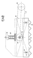
- Figure 2 is a view showing the head of Figure 1 in the 180°-rotated position for detaching the group of sections from it;
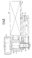
- Figure 3 is a partly sectional plan view on the plane III-III of Figure 1;
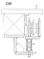
- Figure 4 is an enlarged section taken on the plane IV-IV of Figure 1;
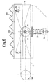
- Figure 5 is an enlarged section taken on the plane V-V of Figure 2; and
- Figures 6 to 10 are example diagrams showing in greater detail and in sequence the operating stages of the head according to the invention shown in Figures 1 to 5.
-
- On the drawings the
reference numeral 10 indicates an electromagnetic head extending radially from ahub 11 rigid with ashaft 12. - On said
shaft 12 there is mounted the section expulsion device consisting of abar 13 idly mounted on theshaft 12 via ahub 14. - With said
bar 13 there cooperates acam 15 extending laterally from a pair ofarms 16 idly mounted on theshaft 12. Thecam 15 is rotated, together with thehead 10, by adrive chain 17 extending between asprocket wheel 18 rigid with theshaft 12 and asprocket wheel 19 provided at the free end of the pair ofarms 16. - A
counteracting spring 20 acts between thehead 10 and the free end of the pair ofarms 16, in correspondence with thecam 15. - As will be explained hereinafter, the
bar 13 is driven relative to thehead 10 with rotary movement guided and limited by aslot 21 provided in thebar 13 and engaging thepin 22 extending from thehead 10. - The
shaft 12 can be rotated for example by a motorizedgearwheel 23 engaging a drivengearwheel 24 rigid with theshaft 12. - The operation of the device according to the invention is clear from the aforegoing description given with reference to the figures, and is briefly as follows.
- An ordered layer of
sections 25 is deposited on theelectromagnetic head 10 in the position shown in Figures 1, 4 and 6, in known manner, for example as described and illustrated in patent application MI96A 001422 filed on 10 July 1996 in the name of the present applicant. - The
electromagnetic head 10 is rotated through about 180° by the drivengearwheel 24, as shown in the sequence illustrated in Figures 6-10 and, by virtue of the action of thecam 15 on the expulsion bar 13 (action counteracted by therear stop 26 of thespring 20 rigid with theelectromagnetic head 10 and by the magnetized sections 25), preloads thespring 20. As a result, as shown in Figures 2, 5 and 10, theexpulsion bar 13 detaches the layer ofsections 25 from theelectromagnetic head 10, simultaneously with its demagnetization. - By rotating in the reverse direction, the
electromagnetic head 10 is then returned to its rest position of Figures 1, 4 and 6 ready to receive afurther layer 25 of sections. During this rotation the action of thecam 15 also ensures that theexpulsion bar 13 becomes repositioned by gravity. - The object stated in the introduction to the description is therefore attained, ie of providing an extremely reliable expulsion device able to satisfy current productivity requirements of modern plants in which, without additional drives but by being connected to the rotary drive for the electromagnetic head, the result is achieved of automatically causing system deactivation during product withdrawal, its preloading during rotation, and then its activation, implemented by the demagnetization of the electromagnetic head.
Claims (3)
- A rotary electromagnetic head (10) with a mechanical expulsion device for automatic stackers of iron sections (25) originating from a rolling mill, characterised in that said expulsion device comprises a bar (13) rotating together with the head (10) but also provided with simultaneous movement relative to the head (10), said relative movement being caused by a cam (15) against the action of a counteracting spring (20).
- An electromagnetic head (10) as claimed in claim 1, characterised in that said bar (13) is idly mounted on a shaft (12) to which the magnetic head (10) is fixed, said cam (15) extending laterally from a pair of arms (16) idly mounted on the shaft (12) and caused to rotate together with the head (10) by a drive chain (17) extending between a sprocket wheel (18) rigid with the shaft (12) and a sprocket wheel (19) provided at the free end of the pair of arms (16), said counteracting spring (20) acting between the head (10) and the free end of the pair of arms (16), in correspondence with the cam (15).
- An electromagnetic head (10) as claimed in claim 1, characterised in that the rotary movement of the bar (13) relative to the head (10) is guided and limited by a slot (21) provided in the bar (13) and engaging a pin (22) extending from the head (10).
Applications Claiming Priority (2)
| Application Number | Priority Date | Filing Date | Title |
|---|---|---|---|
| ITMI962102 | 1996-10-11 | ||
| IT96MI002102A IT1284972B1 (en) | 1996-10-11 | 1996-10-11 | ROTATING ELECTROMAGNETIC HEAD WITH MECHANICAL EJECTOR DEVICE PERFECTED FOR AUTOMATIC STACKERS OF FERROUS PROFILES |
Publications (2)
| Publication Number | Publication Date |
|---|---|
| EP0842879A1 EP0842879A1 (en) | 1998-05-20 |
| EP0842879B1 true EP0842879B1 (en) | 2001-02-28 |
Family
ID=11375016
Family Applications (1)
| Application Number | Title | Priority Date | Filing Date |
|---|---|---|---|
| EP97203121A Expired - Lifetime EP0842879B1 (en) | 1996-10-11 | 1997-10-08 | Rotary electromagnetic head with improved mechanical expulsion device for automatic stackers of iron sections originating from a rolling mill |
Country Status (5)
| Country | Link |
|---|---|
| US (1) | US5915772A (en) |
| EP (1) | EP0842879B1 (en) |
| AT (1) | ATE199361T1 (en) |
| DE (1) | DE69704146D1 (en) |
| IT (1) | IT1284972B1 (en) |
Families Citing this family (2)
| Publication number | Priority date | Publication date | Assignee | Title |
|---|---|---|---|---|
| US11235873B2 (en) * | 2018-03-22 | 2022-02-01 | King Abdullah University Of Science And Technology | Impulsive release mechanism and method |
| CN115744648A (en) * | 2022-11-14 | 2023-03-07 | 中国二十冶集团有限公司 | Hoisting device for transverse movement of rolling mill frame |
Family Cites Families (9)
| Publication number | Priority date | Publication date | Assignee | Title |
|---|---|---|---|---|
| US3856157A (en) * | 1973-02-05 | 1974-12-24 | Mergan Construction Co | Magnet holder for material handling apparatus |
| SU792793A1 (en) * | 1979-08-30 | 1991-07-07 | Предприятие П/Я А-1955 | Magnetic grip |
| DE2935475A1 (en) * | 1979-09-01 | 1981-03-19 | geb. Deyhle Ursula 5750 Menden Menke | Hand held magnetic lifting block - has handle tilted against leaf spring between magnets to free block from lifted sheet |
| IT1158127B (en) * | 1982-07-09 | 1987-02-18 | Danieli Off Mecc | PERFECTED DEVICE FOR PACKING LAMINATED BARS OR LAMINATED PROFILES |
| IT1210526B (en) * | 1985-03-07 | 1989-09-14 | Danieli Off Mecc | ROBOTIC PACKER. |
| SU1289793A1 (en) * | 1985-06-14 | 1987-02-15 | Ленинградский Филиал Проектно-Технологического Института "Энергомонтажпроект" | Gripping device |
| DE3883172T2 (en) * | 1987-12-03 | 1994-02-10 | Danieli Off Mecc | Packaging machine for alternating section layers with a single set of magnetic heads. |
| SU1504196A1 (en) * | 1987-12-30 | 1989-08-30 | Днепродзержинский Индустриальный Институт Им.М.И.Арсеничева | Automatic magnetic grip |
| SU1583344A1 (en) * | 1988-05-11 | 1990-08-07 | Днепродзержинский Индустриальный Институт Им.М.И.Арсеничева | Automatic magnetic cgripper |
-
1996
- 1996-10-11 IT IT96MI002102A patent/IT1284972B1/en active IP Right Grant
-
1997
- 1997-10-08 AT AT97203121T patent/ATE199361T1/en not_active IP Right Cessation
- 1997-10-08 DE DE69704146T patent/DE69704146D1/en not_active Expired - Lifetime
- 1997-10-08 EP EP97203121A patent/EP0842879B1/en not_active Expired - Lifetime
- 1997-10-10 US US08/948,940 patent/US5915772A/en not_active Expired - Fee Related
Also Published As
| Publication number | Publication date |
|---|---|
| IT1284972B1 (en) | 1998-05-28 |
| US5915772A (en) | 1999-06-29 |
| ITMI962102A1 (en) | 1998-04-11 |
| EP0842879A1 (en) | 1998-05-20 |
| DE69704146D1 (en) | 2001-04-05 |
| ATE199361T1 (en) | 2001-03-15 |
Similar Documents
| Publication | Publication Date | Title |
|---|---|---|
| EP1015365B1 (en) | Plate feeder apparatus | |
| EP0522559B1 (en) | Cloth roll exchange apparatus for a loom | |
| US6030171A (en) | Battery plate feeder having oscillating pick-up head | |
| US5024717A (en) | Labelling apparatus | |
| AU670890B2 (en) | Printer | |
| HU197242B (en) | Welding machine for welding ears to plate parts | |
| EP0057525B1 (en) | Yarn winding apparatus | |
| US5915772A (en) | Rotary electromagnetic head with improved mechanical expulsion device for automatic stackers of iron sections originating from a rolling mill | |
| GB2169626A (en) | A double twist winding machine | |
| DE69705661T2 (en) | Process for conveying products | |
| EP0046334A1 (en) | Method and apparatus for automatically mounting non-lead electronic components on printed-circuit or similar boards | |
| US5366171A (en) | Vehicle mounted reel lifting, driving and braking apparatus | |
| CH659444A5 (en) | MACHINE FOR STRAPPING PACKAGES | |
| CA1162841A (en) | Method and apparatus for separating and feeding wrapped articles from a continuous dispenser sheet | |
| US4526360A (en) | Process and apparatus for feeding bands to a pack | |
| EP0592818B1 (en) | Device for storing and taking out blanks | |
| EP1232093B1 (en) | Tensioning device for strapping machines | |
| CA2327343C (en) | A tool ring and a nail machine comprising such tool ring | |
| US4173426A (en) | Apparatus for the automatic loading of a continuously working machine | |
| EP0102036B1 (en) | Apparatus for strapping unstable stacks of magazines and the like | |
| CA1316796C (en) | Method and system for feeding a coil of metal strip to an un-coiler and un-coiling the metal strip | |
| EP0819631A2 (en) | Automatic stacker with rotary heads for stacking, in an ordered manner in alternate upright and inverted layers, metal sections originating from a rolling mill | |
| US5232325A (en) | Apparatus for stacking flat objects | |
| JP2780635B2 (en) | Scrap coil processing equipment | |
| US4439262A (en) | Labeling station for articles like bottles |
Legal Events
| Date | Code | Title | Description |
|---|---|---|---|
| PUAI | Public reference made under article 153(3) epc to a published international application that has entered the european phase |
Free format text: ORIGINAL CODE: 0009012 |
|
| AK | Designated contracting states |
Kind code of ref document: A1 Designated state(s): AT BE CH DE DK ES FI FR GB GR IE IT LI LU MC NL PT SE |
|
| AX | Request for extension of the european patent |
Free format text: AL;LT;LV;RO;SI |
|
| 17P | Request for examination filed |
Effective date: 19981105 |
|
| AKX | Designation fees paid |
Free format text: AT BE CH DE DK ES FI FR GB GR IE IT LI LU MC NL PT SE |
|
| RBV | Designated contracting states (corrected) |
Designated state(s): AT BE CH DE DK ES FI FR GB GR IE IT LI LU MC NL PT SE |
|
| GRAG | Despatch of communication of intention to grant |
Free format text: ORIGINAL CODE: EPIDOS AGRA |
|
| 17Q | First examination report despatched |
Effective date: 19991210 |
|
| GRAG | Despatch of communication of intention to grant |
Free format text: ORIGINAL CODE: EPIDOS AGRA |
|
| GRAH | Despatch of communication of intention to grant a patent |
Free format text: ORIGINAL CODE: EPIDOS IGRA |
|
| GRAH | Despatch of communication of intention to grant a patent |
Free format text: ORIGINAL CODE: EPIDOS IGRA |
|
| RAP1 | Party data changed (applicant data changed or rights of an application transferred) |
Owner name: TECHINT COMPAGNIA TECNICA INTERNAZIONALE S.P.A. |
|
| GRAA | (expected) grant |
Free format text: ORIGINAL CODE: 0009210 |
|
| AK | Designated contracting states |
Kind code of ref document: B1 Designated state(s): AT BE CH DE DK ES FI FR GB GR IE IT LI LU MC NL PT SE |
|
| PG25 | Lapsed in a contracting state [announced via postgrant information from national office to epo] |
Ref country code: SE Free format text: LAPSE BECAUSE OF FAILURE TO SUBMIT A TRANSLATION OF THE DESCRIPTION OR TO PAY THE FEE WITHIN THE PRESCRIBED TIME-LIMIT Effective date: 20010228 Ref country code: NL Free format text: LAPSE BECAUSE OF FAILURE TO SUBMIT A TRANSLATION OF THE DESCRIPTION OR TO PAY THE FEE WITHIN THE PRESCRIBED TIME-LIMIT Effective date: 20010228 Ref country code: LI Free format text: LAPSE BECAUSE OF FAILURE TO SUBMIT A TRANSLATION OF THE DESCRIPTION OR TO PAY THE FEE WITHIN THE PRESCRIBED TIME-LIMIT Effective date: 20010228 Ref country code: IT Free format text: LAPSE BECAUSE OF FAILURE TO SUBMIT A TRANSLATION OF THE DESCRIPTION OR TO PAY THE FEE WITHIN THE PRE;WARNING: LAPSES OF ITALIAN PATENTS WITH EFFECTIVE DATE BEFORE 2007 MAY HAVE OCCURRED AT ANY TIME BEFORE 2007. THE CORRECT EFFECTIVE DATE MAY BE DIFFERENT FROM THE ONE RECORDED.SCRIBED TIME-LIMIT Effective date: 20010228 Ref country code: FR Free format text: LAPSE BECAUSE OF FAILURE TO SUBMIT A TRANSLATION OF THE DESCRIPTION OR TO PAY THE FEE WITHIN THE PRESCRIBED TIME-LIMIT Effective date: 20010228 Ref country code: FI Free format text: LAPSE BECAUSE OF FAILURE TO SUBMIT A TRANSLATION OF THE DESCRIPTION OR TO PAY THE FEE WITHIN THE PRESCRIBED TIME-LIMIT Effective date: 20010228 Ref country code: ES Free format text: THE PATENT HAS BEEN ANNULLED BY A DECISION OF A NATIONAL AUTHORITY Effective date: 20010228 Ref country code: CH Free format text: LAPSE BECAUSE OF FAILURE TO SUBMIT A TRANSLATION OF THE DESCRIPTION OR TO PAY THE FEE WITHIN THE PRESCRIBED TIME-LIMIT Effective date: 20010228 Ref country code: BE Free format text: LAPSE BECAUSE OF FAILURE TO SUBMIT A TRANSLATION OF THE DESCRIPTION OR TO PAY THE FEE WITHIN THE PRESCRIBED TIME-LIMIT Effective date: 20010228 Ref country code: AT Free format text: LAPSE BECAUSE OF FAILURE TO SUBMIT A TRANSLATION OF THE DESCRIPTION OR TO PAY THE FEE WITHIN THE PRESCRIBED TIME-LIMIT Effective date: 20010228 |
|
| REF | Corresponds to: |
Ref document number: 199361 Country of ref document: AT Date of ref document: 20010315 Kind code of ref document: T |
|
| REG | Reference to a national code |
Ref country code: CH Ref legal event code: EP |
|
| REF | Corresponds to: |
Ref document number: 69704146 Country of ref document: DE Date of ref document: 20010405 |
|
| REG | Reference to a national code |
Ref country code: IE Ref legal event code: FG4D |
|
| PG25 | Lapsed in a contracting state [announced via postgrant information from national office to epo] |
Ref country code: PT Free format text: LAPSE BECAUSE OF FAILURE TO SUBMIT A TRANSLATION OF THE DESCRIPTION OR TO PAY THE FEE WITHIN THE PRESCRIBED TIME-LIMIT Effective date: 20010528 |
|
| PG25 | Lapsed in a contracting state [announced via postgrant information from national office to epo] |
Ref country code: DE Free format text: LAPSE BECAUSE OF FAILURE TO SUBMIT A TRANSLATION OF THE DESCRIPTION OR TO PAY THE FEE WITHIN THE PRESCRIBED TIME-LIMIT Effective date: 20010529 |
|
| PG25 | Lapsed in a contracting state [announced via postgrant information from national office to epo] |
Ref country code: DK Free format text: LAPSE BECAUSE OF FAILURE TO SUBMIT A TRANSLATION OF THE DESCRIPTION OR TO PAY THE FEE WITHIN THE PRESCRIBED TIME-LIMIT Effective date: 20010531 |
|
| PG25 | Lapsed in a contracting state [announced via postgrant information from national office to epo] |
Ref country code: GR Free format text: LAPSE BECAUSE OF FAILURE TO SUBMIT A TRANSLATION OF THE DESCRIPTION OR TO PAY THE FEE WITHIN THE PRESCRIBED TIME-LIMIT Effective date: 20010601 |
|
| EN | Fr: translation not filed | ||
| NLV1 | Nl: lapsed or annulled due to failure to fulfill the requirements of art. 29p and 29m of the patents act | ||
| REG | Reference to a national code |
Ref country code: CH Ref legal event code: PL |
|
| PG25 | Lapsed in a contracting state [announced via postgrant information from national office to epo] |
Ref country code: MC Free format text: LAPSE BECAUSE OF NON-PAYMENT OF DUE FEES Effective date: 20011008 Ref country code: LU Free format text: LAPSE BECAUSE OF NON-PAYMENT OF DUE FEES Effective date: 20011008 Ref country code: IE Free format text: LAPSE BECAUSE OF FAILURE TO SUBMIT A TRANSLATION OF THE DESCRIPTION OR TO PAY THE FEE WITHIN THE PRESCRIBED TIME-LIMIT Effective date: 20011008 Ref country code: GB Free format text: LAPSE BECAUSE OF NON-PAYMENT OF DUE FEES Effective date: 20011008 |
|
| REG | Reference to a national code |
Ref country code: GB Ref legal event code: IF02 |
|
| PLBE | No opposition filed within time limit |
Free format text: ORIGINAL CODE: 0009261 |
|
| STAA | Information on the status of an ep patent application or granted ep patent |
Free format text: STATUS: NO OPPOSITION FILED WITHIN TIME LIMIT |
|
| 26N | No opposition filed | ||
| GBPC | Gb: european patent ceased through non-payment of renewal fee |
Effective date: 20011008 |
|
| REG | Reference to a national code |
Ref country code: IE Ref legal event code: MM4A |