EP0842675A2 - System and method for adjusting sensor threshold in a rate responsive pacemaker - Google Patents
System and method for adjusting sensor threshold in a rate responsive pacemaker Download PDFInfo
- Publication number
- EP0842675A2 EP0842675A2 EP97118367A EP97118367A EP0842675A2 EP 0842675 A2 EP0842675 A2 EP 0842675A2 EP 97118367 A EP97118367 A EP 97118367A EP 97118367 A EP97118367 A EP 97118367A EP 0842675 A2 EP0842675 A2 EP 0842675A2
- Authority
- EP
- European Patent Office
- Prior art keywords
- activity
- threshold
- sensor
- data
- pacemaker
- Prior art date
- Legal status (The legal status is an assumption and is not a legal conclusion. Google has not performed a legal analysis and makes no representation as to the accuracy of the status listed.)
- Granted
Links
Images


Classifications
-
- A—HUMAN NECESSITIES
- A61—MEDICAL OR VETERINARY SCIENCE; HYGIENE
- A61N—ELECTROTHERAPY; MAGNETOTHERAPY; RADIATION THERAPY; ULTRASOUND THERAPY
- A61N1/00—Electrotherapy; Circuits therefor
- A61N1/18—Applying electric currents by contact electrodes
- A61N1/32—Applying electric currents by contact electrodes alternating or intermittent currents
- A61N1/36—Applying electric currents by contact electrodes alternating or intermittent currents for stimulation
- A61N1/362—Heart stimulators
- A61N1/365—Heart stimulators controlled by a physiological parameter, e.g. heart potential
- A61N1/36514—Heart stimulators controlled by a physiological parameter, e.g. heart potential controlled by a physiological quantity other than heart potential, e.g. blood pressure
- A61N1/36542—Heart stimulators controlled by a physiological parameter, e.g. heart potential controlled by a physiological quantity other than heart potential, e.g. blood pressure controlled by body motion, e.g. acceleration
Definitions
- This invention relates to rate responsive cardiac pacemakers and, more particularly, to adjustment of the sensor or sensors used for controlling pacing rate.
- Rate responsive cardiac pacemakers provide the benefit of varying pacing rate in accordance with patient cardiac demand.
- the rate responsive (RR) pacemaker increases pacing rate, resulting in increased cardiac output.
- the pacing rate is allowed to drop to a low rate, which has the dual benefit of corresponding to reduced patient demand and also saving pacemaker battery energy.
- RR pacing systems have become very popular, and are designated by the letter R, e.g., VVIR, DDDR, etc.
- the reliability of a rate responsive pacemaker is understandably tied to the sensor, or sensors used to monitor one or more parameters indicative of desired pacing rate.
- the preferred sensor used in the pacemaker system and method of this invention is the activity sensor, which is a transducer that provides an output corresponding to body movement or activity, which output is transformed into an activity count which is representative of desired pacing rate.
- the activity sensor which is a transducer that provides an output corresponding to body movement or activity, which output is transformed into an activity count which is representative of desired pacing rate.
- ACT refers to the number of counts from the activity sensor during a unit of time, specifically 20 seconds.
- an activity-type sensor means a transducer and circuit which provides an output each time the transducer output rises above a predetermined level.
- a problem that must be solved in a rate responsive pacemaker utilizing an activity-type sensor is that of properly setting the sensor threshold, ACT_Th, for producing a count.
- the transducer delivers an analog signal that rises in amplitude and/or frequency in response to body movement, and when the signal exceeds ACT-Th, a count is produced.
- the problem is to set or program a threshold that is optimum for the pacemaker and patient involved, i.e., one which is sensitive enough to properly detect body movement, but which is sufficiently insensitive so that it does not sense small extraneous movements such as due to the patient's own heart contraction, or respiration. While often the threshold can be set at a median, or nominal acceptable level at the time of implant, circumstances may change which indicate a change in ACT_Th.
- the initial setting might not be optimal. It is noted that for some rate response pacemakers, automatic correlation optimization may correct for an incorrect sensor setting. However, for sensors such as activity, if threshold is incorrectly set, the response can be simply on or off, and the correlation algorithm cannot provide correction. Further, there is a chance that the pocket characteristics may change in time, particularly after implant, by healing of the pocket and further by change in weight, or a change in life style or fitness level. Note also that it is desired to provide automatic adjustment to save the physician programming valuable time. We have made studies of patients with implanted pacemakers where data was recorded at different activity threshold settings.
- the counts decrease from the lowest bin to the highest bin, except for the circumstance where the sensor is providing false positives due to the patient heart contractions.
- the percentage of rest can be defined as the percentage of time where the number of activity counts is less than 5 counts/20 sec. Even when the patient is presumed to be sitting quietly, there may be extra events that are counted, but an ACT of 5 appears to be an accurate break point between rest and activity, even though absolute rest can better be indicated as less than 2 counts/20 sec.
- This data also reflects that when cardiac contractions are detected by the activity sensor, i.e., false positives, a relatively large peak can be seen in a bin around the heart frequency, i.e., 20-40 counts/20 sec.
- a rate responsive pacemaker having at least one sensor responsive to patient activity for deriving a signal indicative of desired pacing rate, the sensor output feeding a circuit for providing an activity output whenever the sensor signal exceeds a given threshold, and for providing automatic adjustment of the activity sensor threshold when conditions indicate that an adjustment would provide an improved indication of desired pacing rate.
- a rate responsive pacemaker having at least an activity-type sensor which produces a signal corresponding to patient activity, and processing circuitry for processing the signal to provide an indication of desired pacing rate.
- the processing circuitry provides an output count whenever the sensor exceeds a given threshold, and a determination is made of the rate of counts, from which the desired pacing rate is determined.
- the activity counts are processed over a predetermined adjustment period, e.g., a week, and analyzed to provide an activity count profile, or history.
- a count histogram is accumulated with the counts in different histogram bins representing the number of counts per a given increment of time which had occurred within respective different count ranges. From this histogram data a determination is made as to whether the activity threshold should be adjusted, and if so, in what direction and by how much. The determination is made by comparing the accumulated histogram data to predetermined criteria to see whether the activity count data has a profile within expected ranges. The invention further provides for checking accumulated data to see whether there is an indication of false positives due to counting patient heart contractions as activity.
- FIG. 1 is a block diagram illustrating the basic circuit components of a pacemaker in accordance with this invention.
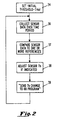
- FIG. 2 is a brief flow diagram showing the primary steps of the process of this invention.
- Figure 3 is a flow diagram that is a more detailed flow diagram of the steps taken in collecting sensor data over a period of time and determining whether sensor threshold should be adjusted.
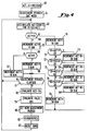
- Figure 4 is a detailed flow diagram showing specific steps for accumulating a count histogram for use in adjustment of an activity sensor threshold, in accordance with this invention.
- Figure 5 is a detailed flow diagram of the steps taken in evaluating activity count data and adjusting activity threshold when indicated.
- Figure 6A is a flow diagram illustrating the steps taken to determine whether it is likely that the pacemaker activity counts contain false positives, i.e., whether activity counts reflect patient cardiac contractions as opposed to actual exercise.
- Figure 6B is a flow diagram illustrating steps taken in response to an indication of false positives from the activity sensor.
- FIG. 1 there are illustrated the primary components of a pacemaker in accordance with this invention, including an activity sensor and an activity amplifier for providing activity counts.
- the pacemaker is illustrated as a dual chamber pacemaker, but it is to be understood that the system and method of this invention are applicable to a single chamber, dual chamber, or indeed multiple chamber pacemaker.
- a ventricular pace generator 15 is illustrated as providing pacing pulses to one or more ventricular electrodes illustrated at 16.
- an atrial pulse generator 18 provides pacing pulses to one or more atrial electrodes illustrated at 19.
- the timing and characteristics of the delivered ventricular and/or atrial pace pulses are controlled by control block 20, which suitably includes a microprocessor in a well-known fashion.
- the microprocessor interconnects with memory 21.
- Sense signals at the ventricular and atrial electrodes are transmitted to QRS sense circuit 24 and P-wave sense circuit 25, respectively, the outputs of which are connected through to control block 20 for controlling timing of the pacemaker, in a known manner.
- an activity sensor 29 is illustrated, which suitably is a transducer that responds to motion and provides an analog output which is inputted to activity amplifier 28.
- Amplifier 28 has an adjustable threshold which is controlled by control block 20, as indicated. Whenever the output of the sensor 29 exceeds the threshold value, the activity amplifier provides a pulse output which is delivered to control block 20, for processing and control purposes.
- the threshold is suitably set so that any signal excursions from the sensor which are truly reflective of activity produce a pulse output, hereinafter referred to as a count; while at the same time the threshold is high enough that the pacemaker is insensitive to noise and random signals which are not reflective of patient activity, e. g., respiration, cardiac contraction, and other extraneous events. Circuits for providing adjustment of thresholds are well known in the art, and many present day pacemakers provide for programmability of amplifier thresholds.
- a pacemaker may utilize an activity sensor together with a second sensor, obtaining information from each of the two or more sensors.
- QT interval is a second rate-indicating parameter, in which case a T-sense amplifier is also provided, as illustrated at 26.
- the invention specifically contemplates application to a dual or multiple sensor rate responsive pacemaker, where one or more of the sensors is of the type that generates an output pulse, or count, when the sensor signal exceeds a predetermined threshold.
- a programmer receiver for receiving data from an external programmer and connecting it through to the control block 20, in a known manner.
- the initial threshold (Th 0 ) is set.
- the pacemaker is initially set at the factory; it may be set to a default setting when switching the Activity sensor on, or may be set by the physician at another setting. Following implant, it is necessary to let conditions stabilize, since ACT threshold should be set only after initial variations caused by healing of the pocket and recovering of the patient after implant have faded.
- sensor data is collected over a period of time, e.g., two weeks, as represented at block 36. After expiration of the collection time period, the sensor data is processed and compared to one or more references to determine whether it is suitable.
- the pacemaker looks to determine whether the data appears to reflect excessive activity counts, which would represent too low a threshold, or does not reflect sufficient activity counts for a patient known to have exercised, which would reflect too high a threshold.
- the sensor threshold is adjusted, assuming that the data indicates that an adjustment is desired.
- the change in threshold is sent to the rate response program for adjustment of that program if required.
- a change in sensor threshold may or may not result in a need to change the correlation algorithm, depending upon the nature of the sensor output and also the correlation algorithm itself.
- the process loops back to step 36 and again starts to collect sensor data over a predetermined time period, which time period itself can be adjusted based upon the pacemaker history.
- FIG. 3 there is shown a somewhat more detailed flow diagram of steps taken in gathering data with which to analyze sensor threshold, and subsequent adjustment of sensor threshold where indicated.
- the sensor is activated, as indicated at block 40.
- the pacemaker also sets sensor limits, or criteria for determining whether the sensor threshold is properly set. These sensor limits or criteria are suitably programmed at the time of implant. For example, as discussed above, the bin limits for collecting data in histogram bins, as well as decision percentages, are entered into memory for use in processing of the collected data. Following this, as indicated at 42, a sensor adjustment period is determined and stored in the pacemaker.
- the initial adjustment period may be relatively short, in the range of about one week, although subsequently greater time periods may be adapted on the assumption that conditions have stabilized and less frequent examination is required.
- the sensor threshold is initializied, usually by programming a nominal mid-range value.
- the pacemaker collects sensor data during the adjustment period.
- activity counts are collected over a 20 second interval to provide an ACT value, which is then stored in an appropriate bin, e.g., less than 10, 10-20, etc.
- the ACT counter is then cleared and the next 20 second count is obtained, this being repeated throughout the predetermined adjustment period.
- the sensor data is processed as indicated at block 45. Such processing may, for example, include comparing counts in each histogram bin and determining whether the count in one or more bins reflects a percentage of all counts that is within a prescribed range.
- this involves determining whether the bin representing ACT ⁇ 10 constitutes between 60 and 80% of all counts. It is to be noted that any criteria may be established, simple or complex, for making an evaluation as to whether the sensor output is acceptable and within limits.
- the sensor threshold is adjusted, if at step 48 the data is determined to be not within limits.
- the pacemaker signals the rate response algorithm that an adjustment has been made, i.e., the information concerning the threshold adjustment is given to the rate response algorithm for an adjustment algorithm if necessary.
- the change in threshold is transferred to the RR routine, for possible use in adjusting the RR correlation algorithm.
- the pacemaker determines whether to adapt the adjustment period, i.e., lengthen it, and also carries out any indicated diagnostics. It is noted that with time, and also considering whether there have been any earlier cases where a threshold adjustment has been found to be necessary, the adjustment period can be lengthened. A change in the adjustment period can be made automatically or by physician programming. Likewise, all or any selected portion of the sensor data can be stored for diagnostic evaluation, e.g., in combination with other stored data representative of patient conditions and events. After this, the program exits as indicated at A, resets all bin counters, and starts the collection process again at block 44.
- the activity threshold is initially set to a medium setting.
- the adjustment period is initially set to one week.
- the pacemaker accumulates the activity counts for 20 seconds and provides an ACT output.
- ACT ACT is not ⁇ 5
- the 5-10 bin is incremented as shown at 67.
- the algorithm branches to block 70 and increments the ACT >10 bin.
- 71 it is determined whether 10 ⁇ ACT ⁇ 20. If yes, the 10-20 bin is incremented at 71Y, and if no, at 72 it is determined whether 20 ⁇ ACT ⁇ 30. If yes, the 20-30 bin is incremented at 72Y, and if no, at 73 it is determined whether 30 ⁇ 40. If yes, the 30-40 bin is incremented at 73Y, and if no, at 74 it is determined whether 40 ⁇ 50.
- the routine proceeds to block 77 and determines whether the adjustment period has elapsed. If no, the routine branches back to 62 and loops through again to process the next value of ACT. If yes, the routine goes to block 78 and evaluates the data, adjusting ACT_Th where indicated.
- the illustration of the steps involved in adjustment of ACT_Th is provided in Figure 5. Following this, the routine goes to block 79 and evaluates the data for false positives, and follow-up when indicated. A specific illustration of the steps corresponding to block 79 is set forth in Figures 6A and 6B.
- the pacemaker determines whether a new adjustment period is appropriate, and sets same.
- data is stored in relation to the diagnostics program. Following this, the histogram bins, or counters, are reset to 0 at 83, and the routine branches back to start all over again at block 62.
- the pacemaker gets a percentage defined as the ratio of ACT.low to ACT.low + ACT.high, where ACT.low is the value of the ⁇ 10 bin, and ACT.high is all counts over 10.
- ACT.low is the value of the ⁇ 10 bin
- ACT.high is all counts over 10.
- the premise here is that evaluation of the efficacy of the threshold setting can be made by determining whether the percentage of low counts compared to all counts is within the range of 60-80%.
- the percentage is tested to determine whether it is less thin 40. If yes, this indicates that threshold is much too low and the routine branches to block 87 and increments ACT_Th by 2 units.
- the routine goes to 89 and determines whether % is less than 60. If yes, this means that it is between 40 and 60, threshold is moderately low, and the routine branches to block 90 and increments ACT_Th by 1. If the answer at 89 is no, the routine goes to 92 and determines whether % is greater thin 80. If yes, meaning that the percentage is outside of the established desired range and threshold is too high, the routine goes to block 93 and decrements ACT_Th by 1. If the answer at 92 is no, meaning that the Activity.low percentage is within the desired 60-80% range, the routine branches to block 96 and compares the ⁇ 5 and 5-10 bins. As discussed above, this comparison enables a determination of whether ACT counts while the patient is at rest are where they should be.
- more than half of the low counts should be in the ⁇ 5 bin, based on the premise that the patient is at rest more than in an active state. If more than half of the low counts are in the ⁇ 5 bin, the routine branches to block 98. However, if the 5-10 bin contains more than half the counts, this indicates that some adjustment should be made, and the routine goes to block 97 and increments ACT_Th by one-half unit. At 98 the bins are reset to 0, and the routine exits.
- FIG. 6A there is shown a routine for making a determination whether it is likely that false positives have been counted, i.e., there are counts that reflect sensor pick-up of heart contractions.
- each successively higher bin should contain fewer counts, meaning that there should be more counts in each bin than there are in the next higher bin.
- What has been found in cases where an activity sensor is picking up heart contractions is that there are an unexpected and excessive number of counts in the range of 20-40, which reflects a heart rate of 60-120.
- the routine of Fig. 6A checks for false positives by determining whether any bin contains fewer counts than the next higher bin. First, at 100, the FP flag is set to false.
- the routine branches to block 106 and sets the FP flag true. If no, the routine branches to 102, then to 103, and then to 104, and in each instance makes the corresponding test. If in any case a bin is found to have accumulated fewer counts than the next higher bin, then the routine branches to block 106 and sets the flag true. If not, the routine exists.
- the pacemaker can run an FP test over a predetermined test duration, as indicated at block 111.
- Such test is suitably done by programming rate changes, overdriving the heart with varying rates, and seeing if activity counts corresponding to the pacing rate are detected.
- the pacemaker would look for ACT values in the range of 40 (since ACT, corresponds to 20 second intervals).
- Another manner of carrying out the test is to compare variations of ACT and QT over a period of time, and to analyze the comparison. If ACT does not follow QT to within given criteria, it can be concluded that ACT - Th is influenced by false positives.
- the activity threshold is acceptable, or whether there are indeed too many false positives being detected. If the answer is that ACT_Th is not acceptable, then at 115 one or more steps can be taken.
- a relatively simple step is to increment ACT_Th, and examine the results over a period of time to see whether the decrease in sensitivity solves the problem. Alternate solutions include subtracting a predetermined number of counts corresponding to the heart beat; and blocking the activity sensor during a time window around the instant of each evoked response, and correcting for some real activity counts that would be blanked in such an event.
- the threshold adjustment enables continued accurate correlation between real patient activity and pacing rate.
- the invention also provides for the determination of false positives due to sensing extraneous conditions such as cardiac contractions, and adjusting threshold when such false positives are found.
Abstract
Description
Claims (6)
- A rate responsive cardiac pacemaker having a controllable pulse generator (15, 18) for generating pacing pulses at a controllable rate, and rate control means (20, 28, 29) responsive to patient activity for controlling said rate, said rate control means comprisingactivity sensor means for continuously providing an activity signal representative of patient activity and having a varying amplitude (29), and for producing an output count signal whenever said activity signal exceeds a predetermined amplitude threshold (28),rate means for generating a rate control signal as a function of produced count signals (20),data means (36) for accumulating data reflective of the history of said output count signals, andadjusting means (37, 38; Fig. 5) for adjusting said amplitude threshold as a function of said accumulated history.
- The pacemaker as described in claim 1, wherein said data means accumulates ACT counts which represent count signals per predetermined increment of time (62).
- The pacemaker as described in claim 2, wherein said data means comprises histogram means (Fig. 4) for classifying and accumulating said ACT counts in predetermined histogram bins, and said adjusting means has comparing means (Fig. 5) for comparing accumulated bin counts over a given adjustment period and then comparing said accumulated bin counts to predetermined decision criteria.
- The pacemaker as described in claim 1, wherein said adjustment means (96, 97) comprises rest means for determining whether said accumulated data indicates that said threshold is properly set to produce reliable count signals during patient rest.
- The pacemaker as described in claim 1, wherein said rate responsive means comprises an activity sensor circuit (28) with an activity threshold, and said adjustment means comprises FP means (Fig. 6A) for determining whether said accumulated data indicates that said threshold should be adjusted to prevent false positive counts.
- The pacemaker as described in claim 1, wherein said data means comprises time means (36; 61) for determining a period for accumulating data, and enabling means (77) for enabling said adjusting means when a said period has elapsed.
Applications Claiming Priority (2)
| Application Number | Priority Date | Filing Date | Title |
|---|---|---|---|
| US08/744,090 US5720769A (en) | 1996-11-05 | 1996-11-05 | System and method for adjusting sensor threshold in a rate responsive pacemaker |
| US744090 | 1996-11-05 |
Publications (3)
| Publication Number | Publication Date |
|---|---|
| EP0842675A2 true EP0842675A2 (en) | 1998-05-20 |
| EP0842675A3 EP0842675A3 (en) | 1999-03-03 |
| EP0842675B1 EP0842675B1 (en) | 2006-02-01 |
Family
ID=24991392
Family Applications (1)
| Application Number | Title | Priority Date | Filing Date |
|---|---|---|---|
| EP97118367A Expired - Lifetime EP0842675B1 (en) | 1996-11-05 | 1997-10-22 | System for adjusting sensor threshold in a rate responsive pacemaker |
Country Status (3)
| Country | Link |
|---|---|
| US (1) | US5720769A (en) |
| EP (1) | EP0842675B1 (en) |
| DE (1) | DE69735178T2 (en) |
Cited By (3)
| Publication number | Priority date | Publication date | Assignee | Title |
|---|---|---|---|---|
| DE19938376A1 (en) * | 1999-08-06 | 2001-02-08 | Biotronik Mess & Therapieg | Device for the detection of fusion events when electrostimulation of the heart |
| DE19958735A1 (en) * | 1999-12-06 | 2001-06-07 | Biotronik Mess & Therapieg | Operating method for a cardiological device implant, in particular a pacemaker |
| DE19963245A1 (en) * | 1999-12-17 | 2001-06-21 | Biotronik Mess & Therapieg | Pacemaker with position detector |
Families Citing this family (31)
| Publication number | Priority date | Publication date | Assignee | Title |
|---|---|---|---|---|
| US6247812B1 (en) * | 1997-09-25 | 2001-06-19 | Vismed | System and method for diagnosing and treating a target tissue |
| US6539249B1 (en) * | 1998-05-11 | 2003-03-25 | Cardiac Pacemakers, Inc. | Method and apparatus for assessing patient well-being |
| US7224825B2 (en) * | 2002-04-18 | 2007-05-29 | Lockheed Martin Corporation | Detecting and identifying hazardous substances contained in mail articles |
| US7136705B1 (en) | 2002-05-31 | 2006-11-14 | Pacesetter, Inc. | Method and apparatus for monitoring sensor performance during rate-responsive cardiac stimulation |
| US7189204B2 (en) * | 2002-12-04 | 2007-03-13 | Cardiac Pacemakers, Inc. | Sleep detection using an adjustable threshold |
| US8589174B2 (en) * | 2003-12-16 | 2013-11-19 | Adventium Enterprises | Activity monitoring |
| US7676262B1 (en) | 2004-04-20 | 2010-03-09 | Pacesetter, Inc. | Methods and devices for determining exercise compliance diagnostics |
| US7031766B1 (en) | 2004-04-20 | 2006-04-18 | Pacesetter, Inc. | Methods and devices for determining exercise diagnostic parameters |
| US8504152B2 (en) | 2007-04-04 | 2013-08-06 | Pacesetter, Inc. | System and method for estimating cardiac pressure based on cardiac electrical conduction delays using an implantable medical device |
| US8208999B2 (en) | 2007-04-04 | 2012-06-26 | Pacesetter, Inc. | System and method for estimating electrical conduction delays from immittance values measured using an implantable medical device |
| US9320448B2 (en) | 2008-04-18 | 2016-04-26 | Pacesetter, Inc. | Systems and methods for improved atrial fibrillation (AF) monitoring |
| US20140249838A1 (en) * | 2013-03-04 | 2014-09-04 | David A. Gelb | Medical implant management |
| US20140358472A1 (en) * | 2013-05-31 | 2014-12-04 | Nike, Inc. | Dynamic sampling |
| US10512424B2 (en) | 2013-12-23 | 2019-12-24 | Medtronic, Inc. | Method and apparatus for selecting activity response vector |
| US9814887B2 (en) | 2014-02-06 | 2017-11-14 | Medtronic, Inc. | Selection of optimal accelerometer sensing axis for rate response in leadless pacemaker |
| US9452292B2 (en) | 2014-02-24 | 2016-09-27 | Medtronic, Inc. | Method and apparatus for detecting loss of capture |
| US9724518B2 (en) * | 2014-11-25 | 2017-08-08 | Medtronic, Inc. | Dynamic patient-specific filtering of an activity signal within a beating heart |
| US9750943B2 (en) | 2015-02-26 | 2017-09-05 | Medtronic, Inc. | Monitoring of pacing capture using acceleration |
| US9937352B2 (en) | 2015-10-22 | 2018-04-10 | Medtronic, Inc. | Rate responsive cardiac pacing control using posture |
| US10207116B2 (en) | 2016-12-01 | 2019-02-19 | Medtronic, Inc. | Pacing mode switching in a ventricular pacemaker |
| US10864377B2 (en) | 2016-12-01 | 2020-12-15 | Medtronic, Inc. | Pacing mode switching in a ventricular pacemaker |
| US10328270B2 (en) | 2016-12-13 | 2019-06-25 | Medtronic, Inc. | Input switching in a ventricular intracardiac pacemaker |
| US11185701B2 (en) | 2018-04-09 | 2021-11-30 | Medtronic, Inc. | Pacing mode switching and rate response limit in a ventricular pacemaker |
| EP4257179A3 (en) | 2018-06-28 | 2023-12-13 | Medtronic, Inc. | Pacing mode switching in a ventricular pacemaker |
| US11207526B2 (en) | 2018-11-14 | 2021-12-28 | Medtronic, Inc. | Methods and apparatus for reducing current drain in a medical device |
| US11260234B2 (en) | 2018-12-06 | 2022-03-01 | Medtronic, Inc. | Mode switching in a ventricular pacemaker to promote atrioventricular conduction |
| US11308783B2 (en) | 2019-05-29 | 2022-04-19 | Medtronic, Inc. | Medical device for fall detection |
| US11707628B2 (en) | 2019-05-30 | 2023-07-25 | Medtronic, Inc. | Rate responsive pacing |
| US11717688B2 (en) | 2020-04-07 | 2023-08-08 | Medtronic, Inc. | Medical device and method for detecting atrioventricular block |
| US11819698B2 (en) | 2020-11-09 | 2023-11-21 | Medtronic, Inc. | Medical device and method for determining atrioventricular synchrony |
| WO2023235680A1 (en) | 2022-06-01 | 2023-12-07 | Medtronic, Inc. | Method and apparatus for detecting oversensing |
Citations (1)
| Publication number | Priority date | Publication date | Assignee | Title |
|---|---|---|---|---|
| US5065759A (en) | 1990-08-30 | 1991-11-19 | Vitatron Medical B.V. | Pacemaker with optimized rate responsiveness and method of rate control |
Family Cites Families (6)
| Publication number | Priority date | Publication date | Assignee | Title |
|---|---|---|---|---|
| US5074302A (en) * | 1989-01-25 | 1991-12-24 | Siemens-Pacesetter, Inc. | Self-adjusting rate-responsive pacemaker and method thereof |
| WO1992003182A1 (en) * | 1990-08-14 | 1992-03-05 | Medtronic, Inc. | Rate responsive pacemaker and methods for optimizing its operation |
| US5154170A (en) * | 1990-08-14 | 1992-10-13 | Medtronic, Inc. | Optimization for rate responsive cardiac pacemaker |
| US5226413A (en) * | 1990-08-14 | 1993-07-13 | Medtronic, Inc. | Rate responsive pacemaker and method for automatically initializing the same |
| US5231986A (en) * | 1992-04-27 | 1993-08-03 | Medtronic, Inc. | Method and system for optimizing activity threshold in activity based rate adaptive pacemakers |
| US5514162A (en) * | 1994-06-07 | 1996-05-07 | Pacesetter, Inc. | System and method for automatically determining the slope of a transfer function for a rate-responsive cardiac pacemaker |
-
1996
- 1996-11-05 US US08/744,090 patent/US5720769A/en not_active Expired - Lifetime
-
1997
- 1997-10-22 DE DE69735178T patent/DE69735178T2/en not_active Expired - Lifetime
- 1997-10-22 EP EP97118367A patent/EP0842675B1/en not_active Expired - Lifetime
Patent Citations (1)
| Publication number | Priority date | Publication date | Assignee | Title |
|---|---|---|---|---|
| US5065759A (en) | 1990-08-30 | 1991-11-19 | Vitatron Medical B.V. | Pacemaker with optimized rate responsiveness and method of rate control |
Cited By (4)
| Publication number | Priority date | Publication date | Assignee | Title |
|---|---|---|---|---|
| DE19938376A1 (en) * | 1999-08-06 | 2001-02-08 | Biotronik Mess & Therapieg | Device for the detection of fusion events when electrostimulation of the heart |
| US6445946B1 (en) | 1999-08-06 | 2002-09-03 | Biotronik Mess-Und Therapiegerate Gmbh & Co. Ingenieurburo Berlin | Apparatus for detecting fusion events upon electrostimulation of the heart |
| DE19958735A1 (en) * | 1999-12-06 | 2001-06-07 | Biotronik Mess & Therapieg | Operating method for a cardiological device implant, in particular a pacemaker |
| DE19963245A1 (en) * | 1999-12-17 | 2001-06-21 | Biotronik Mess & Therapieg | Pacemaker with position detector |
Also Published As
| Publication number | Publication date |
|---|---|
| EP0842675A3 (en) | 1999-03-03 |
| EP0842675B1 (en) | 2006-02-01 |
| DE69735178T2 (en) | 2006-11-02 |
| DE69735178D1 (en) | 2006-04-13 |
| US5720769A (en) | 1998-02-24 |
Similar Documents
| Publication | Publication Date | Title |
|---|---|---|
| US5720769A (en) | System and method for adjusting sensor threshold in a rate responsive pacemaker | |
| EP0870516B1 (en) | Pacemaker system with improved evoked response and repolarization signal detection | |
| US6129745A (en) | Medical device for automatic diagnosis of undersensing by timing | |
| US5549649A (en) | Programmable pacemaker including an atrial rate filter for deriving a filtered atrial rate used for switching pacing modes | |
| EP1509280B1 (en) | Implantable medical device with autosensitivity algorithm for controlling sensing of cardiac signals | |
| US6324427B1 (en) | Implantable cardiac stimulation device having T-wave discrimination of fusion events during autocapture/autothreshold assessment | |
| US5330513A (en) | Diagnostic function data storage and telemetry out for rate responsive cardiac pacemaker | |
| US5755738A (en) | Automatic sensing level adjustment for implantable cardiac rhythm management devices | |
| US5741312A (en) | Pacemaker system and method with improved capture detection and threshold search | |
| US7426412B1 (en) | Evoked potential and impedance based determination of diaphragmatic stimulation | |
| US7123963B2 (en) | Method of automatic evoked response sensing vector selection using evoked response waveform analysis | |
| US6731985B2 (en) | Implantable cardiac stimulation system and method for automatic capture verification calibration | |
| US20030120319A1 (en) | Rate-adaptive therapy with sensor cross-checking | |
| EP0621055A2 (en) | Rate adaptive pacemaker with adjustment of sensor rate as a function of sensed sinus rate | |
| EP0830877A2 (en) | Pacemaker with safety pacing | |
| EP0543939A1 (en) | Optimization for rate responsive cardiac pacemaker. | |
| EP2324763A1 (en) | Systems and methods for off-line reprogramming of implantable medical device components to reduce false detections of cardiac events | |
| US4505276A (en) | Device for detecting retrograde conduction | |
| US6865414B1 (en) | Apparatus and method for automatically sensing threshold histogram with differentiation of sinus from ectopic beats | |
| US5454836A (en) | VDD (R) pacing system | |
| US5423867A (en) | Rate-responsive pacemaker having automatic sensor threshold with programmable offset | |
| US8175708B1 (en) | System and method for adjusting automatic sensitivity control parameters based on intracardiac electrogram signals | |
| EP2654888A2 (en) | Rate initialization and overdrive pacing for capture threshold testing | |
| US6266565B1 (en) | Method and apparatus for detecting and displaying P-wave and R-wave histograms for an implant medical device | |
| US5669392A (en) | Device for varying the threshold detection level of a sensor |
Legal Events
| Date | Code | Title | Description |
|---|---|---|---|
| PUAI | Public reference made under article 153(3) epc to a published international application that has entered the european phase |
Free format text: ORIGINAL CODE: 0009012 |
|
| AK | Designated contracting states |
Kind code of ref document: A2 Designated state(s): CH DE FR LI NL SE |
|
| PUAL | Search report despatched |
Free format text: ORIGINAL CODE: 0009013 |
|
| AK | Designated contracting states |
Kind code of ref document: A3 Designated state(s): AT BE CH DE DK ES FI FR GB GR IE IT LI LU MC NL PT SE |
|
| 17P | Request for examination filed |
Effective date: 19990217 |
|
| AKX | Designation fees paid |
Free format text: CH DE FR LI NL SE |
|
| 17Q | First examination report despatched |
Effective date: 20031001 |
|
| GRAP | Despatch of communication of intention to grant a patent |
Free format text: ORIGINAL CODE: EPIDOSNIGR1 |
|
| RTI1 | Title (correction) |
Free format text: SYSTEM FOR ADJUSTING SENSOR THRESHOLD IN A RATE RESPONSIVE PACEMAKER |
|
| GRAS | Grant fee paid |
Free format text: ORIGINAL CODE: EPIDOSNIGR3 |
|
| GRAA | (expected) grant |
Free format text: ORIGINAL CODE: 0009210 |
|
| AK | Designated contracting states |
Kind code of ref document: B1 Designated state(s): CH DE FR LI NL SE |
|
| REG | Reference to a national code |
Ref country code: CH Ref legal event code: EP |
|
| REG | Reference to a national code |
Ref country code: SE Ref legal event code: TRGR |
|
| REF | Corresponds to: |
Ref document number: 69735178 Country of ref document: DE Date of ref document: 20060413 Kind code of ref document: P |
|
| REG | Reference to a national code |
Ref country code: CH Ref legal event code: NV Representative=s name: ING. MARCO ZARDI C/O M. ZARDI & CO. S.A. |
|
| ET | Fr: translation filed | ||
| PGFP | Annual fee paid to national office [announced via postgrant information from national office to epo] |
Ref country code: CH Payment date: 20061026 Year of fee payment: 10 |
|
| PLBE | No opposition filed within time limit |
Free format text: ORIGINAL CODE: 0009261 |
|
| STAA | Information on the status of an ep patent application or granted ep patent |
Free format text: STATUS: NO OPPOSITION FILED WITHIN TIME LIMIT |
|
| 26N | No opposition filed |
Effective date: 20061103 |
|
| PGFP | Annual fee paid to national office [announced via postgrant information from national office to epo] |
Ref country code: NL Payment date: 20070920 Year of fee payment: 11 |
|
| PGFP | Annual fee paid to national office [announced via postgrant information from national office to epo] |
Ref country code: SE Payment date: 20071005 Year of fee payment: 11 |
|
| REG | Reference to a national code |
Ref country code: CH Ref legal event code: PL |
|
| PG25 | Lapsed in a contracting state [announced via postgrant information from national office to epo] |
Ref country code: LI Free format text: LAPSE BECAUSE OF NON-PAYMENT OF DUE FEES Effective date: 20071031 Ref country code: CH Free format text: LAPSE BECAUSE OF NON-PAYMENT OF DUE FEES Effective date: 20071031 |
|
| EUG | Se: european patent has lapsed | ||
| NLV4 | Nl: lapsed or anulled due to non-payment of the annual fee |
Effective date: 20090501 |
|
| PG25 | Lapsed in a contracting state [announced via postgrant information from national office to epo] |
Ref country code: NL Free format text: LAPSE BECAUSE OF NON-PAYMENT OF DUE FEES Effective date: 20090501 |
|
| PG25 | Lapsed in a contracting state [announced via postgrant information from national office to epo] |
Ref country code: SE Free format text: LAPSE BECAUSE OF NON-PAYMENT OF DUE FEES Effective date: 20081023 |
|
| PGFP | Annual fee paid to national office [announced via postgrant information from national office to epo] |
Ref country code: DE Payment date: 20101029 Year of fee payment: 14 |
|
| PGFP | Annual fee paid to national office [announced via postgrant information from national office to epo] |
Ref country code: FR Payment date: 20111028 Year of fee payment: 15 |
|
| REG | Reference to a national code |
Ref country code: FR Ref legal event code: ST Effective date: 20130628 |
|
| PG25 | Lapsed in a contracting state [announced via postgrant information from national office to epo] |
Ref country code: DE Free format text: LAPSE BECAUSE OF NON-PAYMENT OF DUE FEES Effective date: 20130501 |
|
| REG | Reference to a national code |
Ref country code: DE Ref legal event code: R119 Ref document number: 69735178 Country of ref document: DE Effective date: 20130501 |
|
| PG25 | Lapsed in a contracting state [announced via postgrant information from national office to epo] |
Ref country code: FR Free format text: LAPSE BECAUSE OF NON-PAYMENT OF DUE FEES Effective date: 20121031 |