EP0841661A1 - Disk cartridge anti-rattle mechanism - Google Patents
Disk cartridge anti-rattle mechanism Download PDFInfo
- Publication number
- EP0841661A1 EP0841661A1 EP98100977A EP98100977A EP0841661A1 EP 0841661 A1 EP0841661 A1 EP 0841661A1 EP 98100977 A EP98100977 A EP 98100977A EP 98100977 A EP98100977 A EP 98100977A EP 0841661 A1 EP0841661 A1 EP 0841661A1
- Authority
- EP
- European Patent Office
- Prior art keywords
- door
- cartridge
- cam
- hub
- shell
- Prior art date
- Legal status (The legal status is an assumption and is not a legal conclusion. Google has not performed a legal analysis and makes no representation as to the accuracy of the status listed.)
- Granted
Links
- 230000007246 mechanism Effects 0.000 title abstract description 17
- 230000008878 coupling Effects 0.000 claims description 5
- 238000010168 coupling process Methods 0.000 claims description 5
- 238000005859 coupling reaction Methods 0.000 claims description 5
- 230000000452 restraining effect Effects 0.000 claims 1
- 241000237983 Trochidae Species 0.000 description 2
- 238000013500 data storage Methods 0.000 description 2
- 230000004048 modification Effects 0.000 description 2
- 238000012986 modification Methods 0.000 description 2
- 239000010409 thin film Substances 0.000 description 1
Images


Classifications
-
- G—PHYSICS
- G11—INFORMATION STORAGE
- G11B—INFORMATION STORAGE BASED ON RELATIVE MOVEMENT BETWEEN RECORD CARRIER AND TRANSDUCER
- G11B23/00—Record carriers not specific to the method of recording or reproducing; Accessories, e.g. containers, specially adapted for co-operation with the recording or reproducing apparatus ; Intermediate mediums; Apparatus or processes specially adapted for their manufacture
- G11B23/02—Containers; Storing means both adapted to cooperate with the recording or reproducing means
- G11B23/03—Containers for flat record carriers
- G11B23/0301—Details
- G11B23/0306—Means for locking the record carriers
-
- G—PHYSICS
- G11—INFORMATION STORAGE
- G11B—INFORMATION STORAGE BASED ON RELATIVE MOVEMENT BETWEEN RECORD CARRIER AND TRANSDUCER
- G11B23/00—Record carriers not specific to the method of recording or reproducing; Accessories, e.g. containers, specially adapted for co-operation with the recording or reproducing apparatus ; Intermediate mediums; Apparatus or processes specially adapted for their manufacture
- G11B23/02—Containers; Storing means both adapted to cooperate with the recording or reproducing means
- G11B23/03—Containers for flat record carriers
- G11B23/0301—Details
- G11B23/0308—Shutters
-
- G—PHYSICS
- G11—INFORMATION STORAGE
- G11B—INFORMATION STORAGE BASED ON RELATIVE MOVEMENT BETWEEN RECORD CARRIER AND TRANSDUCER
- G11B23/00—Record carriers not specific to the method of recording or reproducing; Accessories, e.g. containers, specially adapted for co-operation with the recording or reproducing apparatus ; Intermediate mediums; Apparatus or processes specially adapted for their manufacture
- G11B23/02—Containers; Storing means both adapted to cooperate with the recording or reproducing means
- G11B23/03—Containers for flat record carriers
- G11B23/0301—Details
- G11B23/0312—Driving features
-
- G—PHYSICS
- G11—INFORMATION STORAGE
- G11B—INFORMATION STORAGE BASED ON RELATIVE MOVEMENT BETWEEN RECORD CARRIER AND TRANSDUCER
- G11B23/00—Record carriers not specific to the method of recording or reproducing; Accessories, e.g. containers, specially adapted for co-operation with the recording or reproducing apparatus ; Intermediate mediums; Apparatus or processes specially adapted for their manufacture
- G11B23/02—Containers; Storing means both adapted to cooperate with the recording or reproducing means
- G11B23/03—Containers for flat record carriers
- G11B23/032—Containers for flat record carriers for rigid discs
- G11B23/0323—Containers for flat record carriers for rigid discs for disc-packs
Definitions
- This invention relates to data storage drives and more particularly, to a removable cartridge for magnetic disk drives.
- Magnetic disk drives which write and read digital data from flexible magnetic disks have been extensively used. "Floppy disk drives” have been extensively used for small, so-called microcomputer systems, for word-processing applications and the like.
- the flexible disk cartridge includes a relatively thin, flexible jacket which is inserted into the floppy disk drive.
- Rigid disk drives such as the IBM 3350, usually have a fixed rigid magnetic media. The magnetic heads do not contact the magnetic surface, but ride on a thin film of air. Because of this, and other features, these disk drives are capable of extremely precise and high speed operation. This type of disk drive is commonly referred to as a "Winchester" drive. Rigid disks enclosed in a rigid, removable cartridge, or shell have also been used. U.S. Patent 4,864,452-Thompson et al is an example of such a drive.
- the cartridges for these drives have a door which closes the cartridge when it is removed from the drive. This prevents debris from contaminating the magnetic recording medium when the cartridge is not in the drive. When the cartridge is inserted into the drive, this door slides to an open position to provide access for the magnetic recording heads to engage the recording medium.
- a clamping mechanism in a data storage cartridge is actuated when the cartridge is removed from the drive.
- the mechanism restrains the recording medium to prevent rattling.
- the clamping mechanism is driven by the motion of the sliding door.
- the mechanism expands and restrains the media from rattling inside the cartridge during handling.
- the door is opened (cartridge inserted in the drive) the mechanism contracts such that it is free of the hub and the media is free to rotate.
- the mechanism is attached to the sliding door by means of a planar wire which provides a spring coupling to allow for mechanism over travel at both ends of the sliding stroke as well as compliance to account for relative changes in the distance between the mechanism and sliding door attachment point as the door travels through its stroke.
- the clamping mechanism includes a rotating cam which rotates in the same axle as the media, a translating cam follower, a return spring, and an actuating wire which connects the rotating cam to the motion of the sliding cartridge door.
- the mechanism is attached to the cartridge top shell half. It is situated in the cavity formed inside the media hub.
- the mechanism has two states; locked and unlocked. In the locked state the translating cam follower applies a force against the media hub effectively trapping the hub against the cartridge bottom shell. This force is sufficient to prevent the media from rattling against the cartridge shell halves when out of the drive. In the unlocked state the translating cam does not contact the hub thus allowing the media to spin freely.
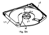
- Figs. 1-4 show a cartridge having two half shells 11 and 12 joined together at 13.
- the cartridge has a front 14, a back 15 and two sides 16 and 17 between substantially flat, planar surfaces 18 and 19.
- An opening 20 in the front of the cartridge provides access by the read/write heads to the recording disks 22, 22A.
- a flexible door 23 covers the opening when the cartridge is removed from the drive.
- a clamping mechanism is actuated as the door 23 is opened and closed.
- This mechanism includes a rotating cam 24 which is rotatable on the same axis as the disks 22.
- the cam 24 has a surface 25 which extends axially as a function of the circumference of the cam.
- Translating cam follower 26 (Fig. 6) is moved axially by the surface 25 as the cam 24 rotates. This axial movement clamps the disk 22 against the bottom half of the shell 11 in the position shown in Fig. 4.
- the rotating cam 24 is connected to the door 23 by the actuating wire 27.
- Actuating wire 27 provides a spring coupling which allows for over-travel at both ends of the stroke of the door 23.
- Spring 27 also provides for relative changes in the distance between the cam 24 and the point 28 at which the actuating wire 27 is attached to the door 23. This distance varies as the door travels through its stroke.
- Recording disks 22 and 22A are mounted on a hub 29 (Figs. 4 and 5A).
- the cam follower 26 applies an axial force to the hub 29 to clamp the recording disk 22 against the bottom wall 11 of the shell.
- a retaining spring 30 is positioned co-axially with the hub 29.
- the retaining spring 30 applies bias to the hub 29 to return it to the position shown in Fig. 3 after it has been translated by the cam follower 26.
- the hub has a cavity at the center thereof in which the clamping mechanism of the present invention is positioned.
Abstract
Description
Claims (10)
- A cartridge for a drive in which read/write heads read/record data on a recording medium comprising:a shell;a recording medium in said shell;said shell having an opening for access by said read/write heads to said recording medium;a door covering said opening when said cartridge is removed from said drive; andclamping means actuated as said door is opened and closed for restraining said medium when said door is closed and freeing said medium for rotation when said door is open.
- The cartridge recited in claim 1 wherein said clamping means comprises:a cam rotatable on the same axis as said recording medium, said cam having a surface which extends axially to clamp said medium when said cam is rotated.
- The cartridge recited in claim 2 further comprising:a translating cam follower which is moved axially by said cam to clamp said medium against one wall of said shell.
- The cartridge recited in claim 2 wherein said cam is connected to said door to rotate said cam as said door is moved between the open and the closed position.
- The cartridge recited in claim 4 wherein said cam is connected to said door by an actuating wire providing a spring coupling which allows for over-travel at both ends of the stroke of said door.
- The actuator recited in claim 5 wherein said door slides in tracks and wherein said spring coupling provides tolerance for relative changes in the distance between said clamping means and the point at which said spring coupling wire is attached to said sliding door as said door travels through its stroke.
- The cartridge recited in claim 3 further comprising:a hub on which said recording medium is mounted, said cam follower applying an axial force to said hub to clamp said medium against a planar wall of said shell.
- The cartridge recited in claim 7 further comprising:a return spring positioned co-axially with said hub, said return spring applying bias to said hub to return it after it has been translated by said cam follower.
- The cartridge recited in claim 8 wherein said surface of said cam extends axially toward said planar wall of said cartridge as a function of the circumference of said cam, said cam urging said hub and attached disk against said planar wall when said door is in the closed position, said return spring urging said hub away from said planar wall as said door is moved to the open position.
- The cartridge recited in claim 8 wherein said hub has a cavity at the center therein and wherein said clamping means is in said cavity.
Priority Applications (1)
| Application Number | Priority Date | Filing Date | Title |
|---|---|---|---|
| EP99202604A EP0977201B1 (en) | 1995-06-07 | 1995-08-14 | Disk cartridge anti-rattle mechanism |
Applications Claiming Priority (3)
| Application Number | Priority Date | Filing Date | Title |
|---|---|---|---|
| US47776495A | 1995-06-07 | 1995-06-07 | |
| US477764 | 1995-06-07 | ||
| EP95650028A EP0747900B1 (en) | 1995-06-07 | 1995-08-14 | Disk cartridge anti-rattle mechanism |
Related Parent Applications (1)
| Application Number | Title | Priority Date | Filing Date |
|---|---|---|---|
| EP95650028A Division EP0747900B1 (en) | 1995-06-07 | 1995-08-14 | Disk cartridge anti-rattle mechanism |
Related Child Applications (1)
| Application Number | Title | Priority Date | Filing Date |
|---|---|---|---|
| EP99202604A Division EP0977201B1 (en) | 1995-06-07 | 1995-08-14 | Disk cartridge anti-rattle mechanism |
Publications (2)
| Publication Number | Publication Date |
|---|---|
| EP0841661A1 true EP0841661A1 (en) | 1998-05-13 |
| EP0841661B1 EP0841661B1 (en) | 1999-10-27 |
Family
ID=23897270
Family Applications (3)
| Application Number | Title | Priority Date | Filing Date |
|---|---|---|---|
| EP99202604A Expired - Lifetime EP0977201B1 (en) | 1995-06-07 | 1995-08-14 | Disk cartridge anti-rattle mechanism |
| EP98100977A Revoked EP0841661B1 (en) | 1995-06-07 | 1995-08-14 | Disk cartridge anti-rattle mechanism |
| EP95650028A Revoked EP0747900B1 (en) | 1995-06-07 | 1995-08-14 | Disk cartridge anti-rattle mechanism |
Family Applications Before (1)
| Application Number | Title | Priority Date | Filing Date |
|---|---|---|---|
| EP99202604A Expired - Lifetime EP0977201B1 (en) | 1995-06-07 | 1995-08-14 | Disk cartridge anti-rattle mechanism |
Family Applications After (1)
| Application Number | Title | Priority Date | Filing Date |
|---|---|---|---|
| EP95650028A Revoked EP0747900B1 (en) | 1995-06-07 | 1995-08-14 | Disk cartridge anti-rattle mechanism |
Country Status (4)
| Country | Link |
|---|---|
| US (1) | US5650899A (en) |
| EP (3) | EP0977201B1 (en) |
| DE (4) | DE69526810T2 (en) |
| HK (2) | HK1009872A1 (en) |
Families Citing this family (18)
| Publication number | Priority date | Publication date | Assignee | Title |
|---|---|---|---|---|
| DE69526810T2 (en) * | 1995-06-07 | 2002-11-21 | Iomega Corp | Record cassette with anti-rattle process |
| US6304417B1 (en) * | 1995-06-07 | 2001-10-16 | Iomega Corporation | Mechanism to clamp magnetic disk against cartridge shell |
| WO1996041344A1 (en) * | 1995-06-07 | 1996-12-19 | Iomega Corporation | Disk cartridge anti-rattle mechanism |
| KR100224829B1 (en) * | 1996-07-10 | 1999-10-15 | 윤종용 | Optical disc drive |
| US6154441A (en) * | 1997-04-17 | 2000-11-28 | Imation Corp. | Method for centering a hub in an optical disc, and an optical storage system using such disc |
| US6339583B1 (en) | 1997-06-20 | 2002-01-15 | Hitachi Maxell, Ltd. | Cartridge for information-recording media having deformable elastic member on shutter |
| US6023398A (en) * | 1997-10-31 | 2000-02-08 | Iomega Corporation | Disk cartridge with rotatable cartridge door |
| US5974026A (en) * | 1997-11-14 | 1999-10-26 | Castlewood Systems, Inc. | Anti-rattle mechanism for a removable video disk cartridge |
| US6243231B1 (en) | 1997-11-25 | 2001-06-05 | Syquest Technology | Disk cartridge with anti-rattle mechanism |
| US6147962A (en) * | 1997-11-26 | 2000-11-14 | Srinivasan; Thiruppathy | Data storage cartridge having a restraining mechanism |
| USD410644S (en) | 1998-05-12 | 1999-06-08 | Castlewood Systems, Inc. | Audio, video, and computer data cartridge |
| USD424048S (en) * | 1998-05-12 | 2000-05-02 | Castlewood Systems, Inc. | Video and computer data cartridge |
| USD411533S (en) | 1998-05-12 | 1999-06-29 | Castlewood Systems, Inc. | Element of an audio video and computer data cartridge |
| USD418828S (en) * | 1998-05-12 | 2000-01-11 | Castlewood Systems, Inc. | Element of an audio, video and computer data cartridge |
| US6154342A (en) * | 1998-06-11 | 2000-11-28 | Imation Corp. | Data storage tape cartridge with reinforcing tape reel lock |
| US6040966A (en) * | 1998-06-11 | 2000-03-21 | Imation Corp. | Data storage tape cartridge with hub alignment insert |
| JP2000067547A (en) * | 1998-08-24 | 2000-03-03 | Sony Corp | Disk cartridge |
| US6141185A (en) | 1998-08-25 | 2000-10-31 | Iomega Corporation | Anti-rattle mechanism for cartridge |
Citations (8)
| Publication number | Priority date | Publication date | Assignee | Title |
|---|---|---|---|---|
| US4400748A (en) * | 1981-04-22 | 1983-08-23 | Iomega Corporation | Flexible magnetic disk drive using a rigid cartridge |
| US4559575A (en) * | 1982-11-22 | 1985-12-17 | Dysan Corporation | Removable disk cartridge with improved door operating mechanism |
| US4608617A (en) * | 1982-08-18 | 1986-08-26 | Fuji Photo Film Co., Ltd. | Magnetic recording disk cartridge |
| JPS62298980A (en) * | 1986-06-18 | 1987-12-26 | Nec Corp | Optical disk cartridge |
| JPS6419572A (en) * | 1987-07-15 | 1989-01-23 | Nec Corp | Optical disk cartridge |
| WO1989008312A1 (en) * | 1988-02-26 | 1989-09-08 | Syquest Technology | Removable cartridge for radial arm voice coil actuated disc drive |
| US4901173A (en) * | 1986-04-21 | 1990-02-13 | Jones David E | Apparatus for coupling record disk to disk drive |
| EP0369651A2 (en) * | 1988-11-14 | 1990-05-23 | Minnesota Mining And Manufacturing Company | Disk locking mechanism for disk cartridge |
Family Cites Families (7)
| Publication number | Priority date | Publication date | Assignee | Title |
|---|---|---|---|---|
| US4320430A (en) * | 1980-04-10 | 1982-03-16 | Memorex Mini Disc Drive Corporation | Recording disc cartridge closure mechanism |
| US4532564A (en) * | 1981-09-16 | 1985-07-30 | Dysan Corporation | Removable disk cartridge |
| JPS598173A (en) * | 1982-07-02 | 1984-01-17 | Mitsubishi Electric Corp | Disc cassette |
| JPS5914167U (en) * | 1982-07-16 | 1984-01-28 | 富士写真フイルム株式会社 | magnetic disk cartridge |
| US4879621A (en) * | 1988-07-11 | 1989-11-07 | Minnesota Mining And Manufacturing Company | Disk restraint |
| US5444586A (en) * | 1992-11-13 | 1995-08-22 | Syquest Technology, Inc. | Removable cartridge for a disk drive with a 1.8 inch form factor |
| DE69526810T2 (en) * | 1995-06-07 | 2002-11-21 | Iomega Corp | Record cassette with anti-rattle process |
-
1995
- 1995-08-14 DE DE69526810T patent/DE69526810T2/en not_active Expired - Fee Related
- 1995-08-14 DE DE69513050T patent/DE69513050T2/en not_active Revoked
- 1995-08-14 DE DE0841661T patent/DE841661T1/en active Pending
- 1995-08-14 DE DE69501886T patent/DE69501886T2/en not_active Revoked
- 1995-08-14 EP EP99202604A patent/EP0977201B1/en not_active Expired - Lifetime
- 1995-08-14 EP EP98100977A patent/EP0841661B1/en not_active Revoked
- 1995-08-14 EP EP95650028A patent/EP0747900B1/en not_active Revoked
- 1995-10-31 US US08/550,818 patent/US5650899A/en not_active Expired - Fee Related
-
1998
- 1998-09-09 HK HK98110544A patent/HK1009872A1/en not_active IP Right Cessation
- 1998-09-10 HK HK98110573A patent/HK1010070A1/en not_active IP Right Cessation
Patent Citations (8)
| Publication number | Priority date | Publication date | Assignee | Title |
|---|---|---|---|---|
| US4400748A (en) * | 1981-04-22 | 1983-08-23 | Iomega Corporation | Flexible magnetic disk drive using a rigid cartridge |
| US4608617A (en) * | 1982-08-18 | 1986-08-26 | Fuji Photo Film Co., Ltd. | Magnetic recording disk cartridge |
| US4559575A (en) * | 1982-11-22 | 1985-12-17 | Dysan Corporation | Removable disk cartridge with improved door operating mechanism |
| US4901173A (en) * | 1986-04-21 | 1990-02-13 | Jones David E | Apparatus for coupling record disk to disk drive |
| JPS62298980A (en) * | 1986-06-18 | 1987-12-26 | Nec Corp | Optical disk cartridge |
| JPS6419572A (en) * | 1987-07-15 | 1989-01-23 | Nec Corp | Optical disk cartridge |
| WO1989008312A1 (en) * | 1988-02-26 | 1989-09-08 | Syquest Technology | Removable cartridge for radial arm voice coil actuated disc drive |
| EP0369651A2 (en) * | 1988-11-14 | 1990-05-23 | Minnesota Mining And Manufacturing Company | Disk locking mechanism for disk cartridge |
Non-Patent Citations (2)
| Title |
|---|
| PATENT ABSTRACTS OF JAPAN vol. 012, no. 194 (P - 713) 7 June 1988 (1988-06-07) * |
| PATENT ABSTRACTS OF JAPAN vol. 013, no. 197 (P - 868) 11 May 1989 (1989-05-11) * |
Also Published As
| Publication number | Publication date |
|---|---|
| EP0977201A1 (en) | 2000-02-02 |
| DE69513050D1 (en) | 1999-12-02 |
| US5650899A (en) | 1997-07-22 |
| EP0747900B1 (en) | 1998-03-25 |
| DE69526810T2 (en) | 2002-11-21 |
| EP0977201B1 (en) | 2002-05-22 |
| EP0841661B1 (en) | 1999-10-27 |
| DE69513050T2 (en) | 2000-04-13 |
| HK1009872A1 (en) | 1999-06-11 |
| EP0747900A1 (en) | 1996-12-11 |
| DE841661T1 (en) | 1998-09-24 |
| DE69526810D1 (en) | 2002-06-27 |
| HK1010070A1 (en) | 1999-06-11 |
| DE69501886D1 (en) | 1998-04-30 |
| DE69501886T2 (en) | 1999-03-18 |
Similar Documents
| Publication | Publication Date | Title |
|---|---|---|
| EP0841661B1 (en) | Disk cartridge anti-rattle mechanism | |
| US5216558A (en) | Drawer loading removable cartridge disk drive | |
| US5768074A (en) | Disk drive cartridge door | |
| US5570252A (en) | Disk drive cartridge door | |
| EP0369651A2 (en) | Disk locking mechanism for disk cartridge | |
| US5862026A (en) | Cam mechanism to clamp magnetic disk against cartridge shell | |
| US5535081A (en) | Immobilizer for a data storage disk in a cartridge using an overcenter spring | |
| US6002556A (en) | Adapter for magnetic disc cartridge | |
| US6141185A (en) | Anti-rattle mechanism for cartridge | |
| US6243231B1 (en) | Disk cartridge with anti-rattle mechanism | |
| US6134081A (en) | Media hub mounting system for minimizing Z-axis during cartridge insertion and ejection translation | |
| US6304417B1 (en) | Mechanism to clamp magnetic disk against cartridge shell | |
| US6172849B1 (en) | Apparatus for retaining a disk cartridge shutter in a closed position | |
| US6160680A (en) | Two-piece media hub and methods of attaching same to a medium | |
| EP0899729A2 (en) | Media hub mounting system for minimizing z-axis translation | |
| US5943197A (en) | Lid assembly for disk cartridge | |
| US20040021986A1 (en) | Disk cartridge and disk drive thereof | |
| US20030021061A1 (en) | Labyrinth seal for removable disk drive cartridge | |
| US20040190200A1 (en) | Magnetic disk cartridge | |
| JPH10320947A (en) | Disk cartridge | |
| JP2001319449A (en) | Magnetic disk cartridge | |
| JPH064951U (en) | Shutter open / close mechanism for disk cartridges | |
| JPH06187759A (en) | Cartridge for disk recording medium |
Legal Events
| Date | Code | Title | Description |
|---|---|---|---|
| PUAI | Public reference made under article 153(3) epc to a published international application that has entered the european phase |
Free format text: ORIGINAL CODE: 0009012 |
|
| AC | Divisional application: reference to earlier application |
Ref document number: 747900 Country of ref document: EP |
|
| AK | Designated contracting states |
Kind code of ref document: A1 Designated state(s): DE FR GB IT |
|
| AX | Request for extension of the european patent |
Free format text: LT PAYMENT 980223;LV PAYMENT 980223;SI PAYMENT 980223 |
|
| DAX | Request for extension of the european patent (deleted) | ||
| EL | Fr: translation of claims filed | ||
| RAX | Requested extension states of the european patent have changed |
Free format text: LT PAYMENT 980223;LV PAYMENT 980223;SI PAYMENT 980223 |
|
| DET | De: translation of patent claims | ||
| 17P | Request for examination filed |
Effective date: 19980917 |
|
| 17Q | First examination report despatched |
Effective date: 19981118 |
|
| GRAG | Despatch of communication of intention to grant |
Free format text: ORIGINAL CODE: EPIDOS AGRA |
|
| GRAG | Despatch of communication of intention to grant |
Free format text: ORIGINAL CODE: EPIDOS AGRA |
|
| GRAH | Despatch of communication of intention to grant a patent |
Free format text: ORIGINAL CODE: EPIDOS IGRA |
|
| GRAG | Despatch of communication of intention to grant |
Free format text: ORIGINAL CODE: EPIDOS AGRA |
|
| GRAH | Despatch of communication of intention to grant a patent |
Free format text: ORIGINAL CODE: EPIDOS IGRA |
|
| GRAA | (expected) grant |
Free format text: ORIGINAL CODE: 0009210 |
|
| AC | Divisional application: reference to earlier application |
Ref document number: 747900 Country of ref document: EP |
|
| AK | Designated contracting states |
Kind code of ref document: B1 Designated state(s): DE FR GB IT |
|
| DAX | Request for extension of the european patent (deleted) | ||
| ITF | It: translation for a ep patent filed |
Owner name: BUGNION S.P.A. |
|
| ET | Fr: translation filed | ||
| REF | Corresponds to: |
Ref document number: 69513050 Country of ref document: DE Date of ref document: 19991202 |
|
| PLBQ | Unpublished change to opponent data |
Free format text: ORIGINAL CODE: EPIDOS OPPO |
|
| PLBI | Opposition filed |
Free format text: ORIGINAL CODE: 0009260 |
|
| 26 | Opposition filed |
Opponent name: CASTLEWOOD SYSTEMS INC. Effective date: 20000131 |
|
| PLBF | Reply of patent proprietor to notice(s) of opposition |
Free format text: ORIGINAL CODE: EPIDOS OBSO |
|
| PLBF | Reply of patent proprietor to notice(s) of opposition |
Free format text: ORIGINAL CODE: EPIDOS OBSO |
|
| PGFP | Annual fee paid to national office [announced via postgrant information from national office to epo] |
Ref country code: FR Payment date: 20010824 Year of fee payment: 7 |
|
| PGFP | Annual fee paid to national office [announced via postgrant information from national office to epo] |
Ref country code: GB Payment date: 20010830 Year of fee payment: 7 |
|
| PGFP | Annual fee paid to national office [announced via postgrant information from national office to epo] |
Ref country code: DE Payment date: 20010907 Year of fee payment: 7 |
|
| REG | Reference to a national code |
Ref country code: GB Ref legal event code: IF02 |
|
| RDAH | Patent revoked |
Free format text: ORIGINAL CODE: EPIDOS REVO |
|
| RDAG | Patent revoked |
Free format text: ORIGINAL CODE: 0009271 |
|
| STAA | Information on the status of an ep patent application or granted ep patent |
Free format text: STATUS: PATENT REVOKED |
|
| 27W | Patent revoked |
Effective date: 20011207 |
|
| GBPR | Gb: patent revoked under art. 102 of the ep convention designating the uk as contracting state |
Free format text: 20011207 |
|
| PLAB | Opposition data, opponent's data or that of the opponent's representative modified |
Free format text: ORIGINAL CODE: 0009299OPPO |