EP0841617A2 - Dynamic allocation of buffer space between requests and responses - Google Patents
Dynamic allocation of buffer space between requests and responses Download PDFInfo
- Publication number
- EP0841617A2 EP0841617A2 EP97111189A EP97111189A EP0841617A2 EP 0841617 A2 EP0841617 A2 EP 0841617A2 EP 97111189 A EP97111189 A EP 97111189A EP 97111189 A EP97111189 A EP 97111189A EP 0841617 A2 EP0841617 A2 EP 0841617A2
- Authority
- EP
- European Patent Office
- Prior art keywords
- request
- response
- limit
- total
- counter
- Prior art date
- Legal status (The legal status is an assumption and is not a legal conclusion. Google has not performed a legal analysis and makes no representation as to the accuracy of the status listed.)
- Granted
Links
Images
Classifications
-
- G—PHYSICS
- G06—COMPUTING; CALCULATING OR COUNTING
- G06F—ELECTRIC DIGITAL DATA PROCESSING
- G06F9/00—Arrangements for program control, e.g. control units
- G06F9/06—Arrangements for program control, e.g. control units using stored programs, i.e. using an internal store of processing equipment to receive or retain programs
- G06F9/46—Multiprogramming arrangements
- G06F9/50—Allocation of resources, e.g. of the central processing unit [CPU]
- G06F9/5005—Allocation of resources, e.g. of the central processing unit [CPU] to service a request
- G06F9/5011—Allocation of resources, e.g. of the central processing unit [CPU] to service a request the resources being hardware resources other than CPUs, Servers and Terminals
- G06F9/5016—Allocation of resources, e.g. of the central processing unit [CPU] to service a request the resources being hardware resources other than CPUs, Servers and Terminals the resource being the memory
Definitions
- This invention relates in general to multi-processor computer systems and in particular to the allocation of queue space between requests and responses.
- the invention partitions a single buffer into space reserved for requests only, space reserved for responses only, and space that can be used for either requests or responses, as needed by the system. Under this arrangement, if at any instant one of the reserved buffers (requests or responses) goes into overflow, the dual use buffers can be used to keep the data flowing efficiently.
- the processor agent chip or PAC has three internal registers that keep track of the status of the buffer space. One counter keeps track of request buffer space, a second counter keeps track of response buffer space, and the third counter keeps track of the total amount of buffer space that is being used. By using the three counters and comparing each of them to three limits, the system is capable of dynamic buffer allocation.
- the limits are set by software and define the maximum number of request packets that can be in the buffer, the maximum number of response packets that can be in the buffer, and the total number of both request and response packets that can be in the buffer.
- the PAC polls counters to insure that the buffer is not full.
- the PAC checks the request counter to ensure that the request limit has not been exceeded, and then the PAC checks the total counter to ensure this packet will not exceed the total limit count for that buffer.
- the limit for the total buffer size is set for ten packets of both response and request types
- the limit for the request count is set for eight packets of the request type. That would mean that the request packet could be sent as long as there was not eight request packets currently in the request buffer and that there was not currently ten total packets of both request and response types in the buffer.
- the limit for the total buffer size is set for ten packets of both response and request types
- the limit for the response count is set for eight packets of the response type. That would mean that the response packet could be sent as long as there was not eight response packets currently in the response buffer and that there was not currently ten total packets of both request and response types in the buffer.
- a technical feature of the invention is to use a single buffer for both request buffer space and response buffer space.
- Another technical feature of the invention is to reserve some buffer space for only requests, to reserve some buffer space for only responses, and to use the remainder of the buffer space for requests or responses, as required by the system.
- a further technical feature of the invention is to use counters to keep track of the status of the different types of buffer spaces, i.e. request, response, and total.
- a further technical feature of the invention is to have the allocation of the different types of buffer spaces software adjustable.
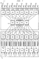
- FIGURE 1 depicts a single node of a multi-node, multi-processor computer system.
- the overall system may have a plurality of these nodes shown in FIGURE 1.
- Each node can support up to sixteen processors 110. These processors are connected to processor agent chips or PACs 111. The function of each PAC 111 is to transmit requests from its associated processors 110 through cross bar router chips (RAC) 112 to the memory access chips (MAC) 113 and then forward the responses back to the requesting processor. Each PAC 111 has an input/output (I/O) subsystem 117. Each MAC 113 controls access to its associated coherent memory 114. When a. processor 110 generates a request to access memory (or other resource), the associated PAC 111 sends the request through the proper RAC 112 to a MAC 113.
- RAC cross bar router chips
- MAC memory access chips
- TAC 115 is the interface between the node and an SCI ring 116.
- TAC 115 is also known as a toroidal access chip or a SCI controller.
- the SCI rings 116 (not shown) interconnect the nodes in the multi-node system.
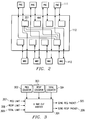
- FIGURE 2 depicts a single RAC chip 112 wherethrough packets flow from PAC 111 to MAC 113, and from MAC 113 to PAC 111.
- RAC chip 112 forms a cross-bar which routes requests and responses in both directions.
- RAC has four PAC input buffers 201, one buffer associated with a respective PAC.
- the RAC also has four MAC input buffers, one buffer associated with a respective MAC.
- Each of the PAC input buffers 201 can hold up to ten packets of both response and request types.
- PAC 111 sends a packet to the RAC 112, and where it is held in the PAC input buffer 201 until only RAC can send the packet on to MAC 113. Similarly for the opposite direction, then the MAC tries to send a packet to a certain PAC, it goes through the proper RAC where it first goes into the input buffer on that RAC and is later on forwarded on to the proper PAC.
- the MAC input buffers are not part of this invention.
- the PAC input buffers will hereinafter be referred to as buffers.
- the processors will make requests for data and provide responses for data. For example, there is a time when processor 110 will make a request for a certain line memory. That request will be forwarded to PAC 111. PAC 111 forwards it to one of the two RACs 112 to which it is connected, and then to the MAC chip 113 that actually has the requested memory line 114. When PAC 111 sends the request to RAC 112, the request is stored in buffer 201, and is later forwarded to the MAC 113. If the request if to a local memory line, MAC will access the memory line from memory and send it back as a response, to the original PAC.
- processor 110 requests a line memory and the line memory is cached in another processor.
- the request goes from PAC 111 to MAC 113, and MAC 113 determines that the line memory is at a remote location, and then sends a request to a second PAC to access the line memory.
- the second PAC routes the request to the appropriate processor, and then sends back the data from the memory line as a response. So in this scenario, the PAC sends response across the RAC to the MAC, where it is eventual delivered to the first PAC wherein the request originated.
- FIGURE 3 depicts the arrangement of cross bar out arbiter 301 that resides in PAC 111.
- Arbiter 301 in conjunction with buffer 201 performs the dynamic buffer allocation.
- Each arbiter 301 has three counter registers 302, 303, 304.
- Counter 302 is a request counter that keeps track of the total number of requests that are currently in use in buffer 201.
- Counter 303 is the response counter that keeps track of the total number of responses that are currently in use in buffer 201.
- Counter 304 is the total counter that keeps track of the total number of buffer locations currently allocated for use by both responses and requests in buffer 201. All three of these counters are used as inputs to cross-bar out arbiter 301.
- the other three inputs to arbiter 301 are the buffer limits, which can, if desired, be set by software.
- Request limit 307 indicates the maximum buffer space that can be used for request packets.
- Response limit 308 indicates the maximum buffer space that can be used for response packets.
- Limit 309 indicates the total size of the buffer or the total amount of both response and request packets that the buffer will hold.
- Cross-bar arbiter 301 uses data from the limit inputs and the counter inputs, decides whether to send a request packet or to send a response packet.
- the PAC has an output directing the dispatch of a request packet and another output directing the dispatch of a response packet. If the request limit is greater than the request counter and the total limit is greater than the total counter, then it is safe to send the request packet. If the response limit is greater than the response counter and the total limit is greater than the total counter, then it is safe to send the response packet. However, if one of these groups of conditions is not met, then the PAC can send the packet with the conditions that are met, thus preventing packet jams. Moreover, when the total limit is the same or less than the total counter, the buffer is full and both packets would be held until the RAC sends information stating that it has freed up some of the buffer locations.
- the buffer space reserved for request packets is the total limit minus the response limit, for the 8/8/10 arrangement discussed previously. This arrangement yields a reserved request space of two.
- the buffer space reserved for response packets is the total limit minus the request limit, for the 8/8/10 arrangement discussed previously, yielding a reserved response space of two.
- the remainder of the buffer space, called the dynamic space is equal to the response limit plus the request limit minus the total limit, for the 8/8/10 arrangement discussed previously and yields a dynamic space of six.
- the 8/8/10 arrangement means at least a total of four spaces are reserved, and six spaces are dynamic. This arrangement has been found to work well at keeping the packets moving.
- a 7/7/10 is less flexible, with only four locations that are dynamically allocable, because three spaces are reserved for requests and three more for responses.
- the PAC Whenever the PAC sends a request packet, it increments both the request counter and the total counter.
- the RAC stores the request until the MAC is ready to receive it.
- the request packet is sent on to the MAC, then the RAC sends a count of the actual number of requests that have been sent out to the MACs.
- the PAC receives this count information from the RAC, the PAC subtracts the number of sent out packets from both the request counter and the total counter. Thus, the counters are decremented when the RAC sends out the request.
- the PAC Whenever the PAC sends a response packet it increments both the response counter and the total counter.
- the RAC stores the response until the MAC is ready to receive it.
- the response packet is sent on to the MAC, then the RAC sends a count of the actual number of responses that have been sent out to the MACs.
- the PAC receives this count information from the RAC, the PAC subtracts the number of sent out packets from both the response counter and the total counter. Thus, the counters are decremented when the RAC sends out the response.
- the RAC has no knowledge of the actual allocation of the buffer space between request and response.
- the RAC knows that it is receiving requests and responses packets, and the number of packets of each type being sent out.
- the RAC sends this information back to the PAC.
- Buffer 201 is ideally physically one buffer and is broken up logically into request buffers and responses buffers. However, the system could work with multiple physical registers.
- the RAC knows which buffer locations are which, and which buffer locations currently contain responses, but it does not receive information about the counters and limits in the PAC.
Abstract
Description
Claims (10)
- A computer system having a processor that creates request packets to access memory and creates response packets that satisfy queries made by the system, the system comprising:a dynamically allocable buffer space for storing and routing the request packets and the response packets; andan arbiter for receiving the request packets and the response packets from the processor, and for making determinations whether to send the request packets and the response packets to the buffer space.
- The computer system of claim 1, wherein said determinations are made in part, under control of:a request counter that stores a number value representing a total number of request packets currently stored in the buffer space;a response counter that stores a number value representing a total number of response packets currently stored in the buffer space;a total counter that stores a number value representing a total number of both request packets and response packets currently stored in the buffer space;a request limit value representing a maximum number of request packets that can be stored in the buffer space;a response limit value representing a maximum number of response packets that can be stored in the buffer space; anda total limit value representing a maximum number of both request packets and response packets that can be stored in the buffer space.
- The computer system of claim 2, wherein:the arbiter compares the request limit with the request counter and compares the total limit with the total counter to determine whether to send the request packet to the buffer space;if the request limit is greater than the request counter, and if the total limit is greater than the total counter, then the arbiter will send the request packet and increment both the request counter and the total counter;if the request limit is not greater than the request counter, then the arbiter compares the response limit with the response counter and compares the total limit with the total counter to determine whether to send the response packet to the buffer space; andif the total limit is not greater than the total counter, then the arbiter will send neither the request packet nor the response packet until the total limit is greater than the total counter.
- The computer system as in claim 2 or 3, wherein:the buffer space transmits the request packet to a location in the system after receiving the request packet from the arbiter, and then relays transmission information to the arbiter; andthe arbiter receives the transmission information and decrements the request counter and the total counter.
- The computer system of claim 2, wherein:the arbiter compares the response limit with the response counter and compares the total limit with the total counter to determine whether to send the response packet to the buffer space;if the response limit is greater than the response counter, and if the total limit is greater than the total counter, then the arbiter will send the response packet and increment both the response counter and the total counter;if the response limit is not grater than the response counter, then the arbiter compares the request limit with the request counter and compares the total limit with the total counter to determine whether to send the request packet to the buffer space; andif the total limit is not greater than the total counter, then the arbiter will send neither the request packet nor the response packet until the total limit is greater than the total counter.
- The computer system as in claim 2 or 5, wherein:the buffer space transmits the response packet to a location in the system after receiving the response packet from the arbiter, and then relays transmission information to the arbiter; andthe arbiter receives the transmission information and decrements the response counter and the total counter.
- The computer system as in one of claims 2-6, wherein:the request limit, the response limit, and the total limit are alterable by software commands.
- The computer system as in one of claims 2-7, wherein:a reserved request space of the buffer space is equal to the total limit minus the response limit;a reserved response space of the buffer space is equal to the total limit minus the request limit; anda dynamically allocable space of the buffer space is equal to the request limit plus the response limit minus the total limit.
- The computer system as in one of claims 2-8, wherein:the request limit is 8;the response limit is 8;the total limit is 10;the reserved request space is 2;the reserved response space is 2; andthe dynamically allocable space is 6.
- A method for dynamically allocating buffer space in a computer system, the method comprising the steps of:accepting request packets to access a memory;accepting response packets that satisfy queries made by the system;determining whether to send the request packets and the response packets to the buffer space;dynamically allocating the buffer space so as to accommodate a maximum number of both request packets and response packets; andstoring the request packets and the response packets in the buffer space.
Applications Claiming Priority (2)
| Application Number | Priority Date | Filing Date | Title |
|---|---|---|---|
| US748226 | 1996-11-12 | ||
| US08/748,226 US5881316A (en) | 1996-11-12 | 1996-11-12 | Dynamic allocation of queue space using counters |
Publications (3)
| Publication Number | Publication Date |
|---|---|
| EP0841617A2 true EP0841617A2 (en) | 1998-05-13 |
| EP0841617A3 EP0841617A3 (en) | 2002-01-16 |
| EP0841617B1 EP0841617B1 (en) | 2004-05-12 |
Family
ID=25008540
Family Applications (1)
| Application Number | Title | Priority Date | Filing Date |
|---|---|---|---|
| EP97111189A Expired - Lifetime EP0841617B1 (en) | 1996-11-12 | 1997-07-03 | Dynamic allocation of buffer space between requests and responses |
Country Status (4)
| Country | Link |
|---|---|
| US (1) | US5881316A (en) |
| EP (1) | EP0841617B1 (en) |
| JP (1) | JPH10187635A (en) |
| DE (1) | DE69729046T2 (en) |
Cited By (5)
| Publication number | Priority date | Publication date | Assignee | Title |
|---|---|---|---|---|
| WO2003034689A1 (en) * | 2001-10-15 | 2003-04-24 | Advanced Micro Devices, Inc. | Apparatus and method for allocating buffer space |
| US6888843B2 (en) | 1999-09-17 | 2005-05-03 | Advanced Micro Devices, Inc. | Response virtual channel for handling all responses |
| US6938094B1 (en) | 1999-09-17 | 2005-08-30 | Advanced Micro Devices, Inc. | Virtual channels and corresponding buffer allocations for deadlock-free computer system operation |
| US6950438B1 (en) | 1999-09-17 | 2005-09-27 | Advanced Micro Devices, Inc. | System and method for implementing a separate virtual channel for posted requests in a multiprocessor computer system |
| US7213098B2 (en) * | 2000-11-28 | 2007-05-01 | Sun Microsystems, Inc. | Computer system and method providing a memory buffer for use with native and platform-independent software code |
Families Citing this family (11)
| Publication number | Priority date | Publication date | Assignee | Title |
|---|---|---|---|---|
| US6345345B1 (en) * | 1999-01-26 | 2002-02-05 | Advanced Micro Devices, Inc. | Data communications device and associated method for arbitrating access using dynamically programmable arbitration scheme and limits on data transfers |
| US6694388B1 (en) * | 2000-05-31 | 2004-02-17 | 3Com Corporation | Dynamic queuing system incorporating multiple queues sharing a single memory |
| US6701387B1 (en) * | 2000-08-31 | 2004-03-02 | Hewlett-Packard Development Company, L.P. | Adaptive data fetch prediction algorithm |
| US6721826B2 (en) * | 2001-09-25 | 2004-04-13 | Lsi Logic Corporation | Buffer partitioning for managing multiple data streams |
| US6877048B2 (en) | 2002-03-12 | 2005-04-05 | International Business Machines Corporation | Dynamic memory allocation between inbound and outbound buffers in a protocol handler |
| US7272496B2 (en) * | 2003-06-12 | 2007-09-18 | Temic Automotive Of North America, Inc. | Vehicle network and method of communicating data packets in a vehicle network |
| US7865684B2 (en) * | 2005-06-27 | 2011-01-04 | Ab Initio Technology Llc | Managing message queues |
| US9069571B2 (en) * | 2010-12-01 | 2015-06-30 | International Business Machines Corporation | Propagation of unique device names in a cluster system |
| US8943082B2 (en) | 2010-12-01 | 2015-01-27 | International Business Machines Corporation | Self-assignment of node identifier in a cluster system |
| US8788465B2 (en) | 2010-12-01 | 2014-07-22 | International Business Machines Corporation | Notification of configuration updates in a cluster system |
| US9183148B2 (en) | 2013-12-12 | 2015-11-10 | International Business Machines Corporation | Efficient distributed cache consistency |
Citations (3)
| Publication number | Priority date | Publication date | Assignee | Title |
|---|---|---|---|---|
| EP0353051A2 (en) * | 1988-07-28 | 1990-01-31 | Oki Electric Industry Co. Ltd. | A method and system for monitoring the number of available buffers |
| US5511214A (en) * | 1992-08-25 | 1996-04-23 | Fujitsu Limited | On-line processing system and overload suppressing method |
| EP0729106A1 (en) * | 1995-02-14 | 1996-08-28 | Nokia Mobile Phones Ltd. | Data interface |
Family Cites Families (6)
| Publication number | Priority date | Publication date | Assignee | Title |
|---|---|---|---|---|
| US4788679A (en) * | 1986-09-02 | 1988-11-29 | Nippon Telegraph And Telephone Corporation | Packet switch with variable data transfer rate links |
| US4922438A (en) * | 1986-12-11 | 1990-05-01 | Siemens Aktiengesellschaft | Method and apparatus for reading packet-oriented data signals into and out of a buffer |
| US5448701A (en) * | 1992-12-22 | 1995-09-05 | International Business Machines Corporation | Flow controller for shared bus used by plural resources |
| US5541932A (en) * | 1994-06-13 | 1996-07-30 | Xerox Corporation | Circuit for freezing the data in an interface buffer |
| US5517615A (en) * | 1994-08-15 | 1996-05-14 | Unisys Corporation | Multi-channel integrity checking data transfer system for controlling different size data block transfers with on-the-fly checkout of each word and data block transferred |
| US5473604A (en) * | 1994-11-21 | 1995-12-05 | At&T Corp. | Method for avoiding node overload in a packet switching network |
-
1996
- 1996-11-12 US US08/748,226 patent/US5881316A/en not_active Expired - Lifetime
-
1997
- 1997-07-03 DE DE69729046T patent/DE69729046T2/en not_active Expired - Fee Related
- 1997-07-03 EP EP97111189A patent/EP0841617B1/en not_active Expired - Lifetime
- 1997-11-05 JP JP30260597A patent/JPH10187635A/en active Pending
Patent Citations (3)
| Publication number | Priority date | Publication date | Assignee | Title |
|---|---|---|---|---|
| EP0353051A2 (en) * | 1988-07-28 | 1990-01-31 | Oki Electric Industry Co. Ltd. | A method and system for monitoring the number of available buffers |
| US5511214A (en) * | 1992-08-25 | 1996-04-23 | Fujitsu Limited | On-line processing system and overload suppressing method |
| EP0729106A1 (en) * | 1995-02-14 | 1996-08-28 | Nokia Mobile Phones Ltd. | Data interface |
Non-Patent Citations (1)
| Title |
|---|
| "BUFFER POOLS: SHARING A COMMON RESOURCE WITH GUARANTEES" IBM TECHNICAL DISCLOSURE BULLETIN, vol. 37, no. 7, 1 July 1994 (1994-07-01), pages 95-97, XP000455451 * |
Cited By (6)
| Publication number | Priority date | Publication date | Assignee | Title |
|---|---|---|---|---|
| US6888843B2 (en) | 1999-09-17 | 2005-05-03 | Advanced Micro Devices, Inc. | Response virtual channel for handling all responses |
| US6938094B1 (en) | 1999-09-17 | 2005-08-30 | Advanced Micro Devices, Inc. | Virtual channels and corresponding buffer allocations for deadlock-free computer system operation |
| US6950438B1 (en) | 1999-09-17 | 2005-09-27 | Advanced Micro Devices, Inc. | System and method for implementing a separate virtual channel for posted requests in a multiprocessor computer system |
| US7213098B2 (en) * | 2000-11-28 | 2007-05-01 | Sun Microsystems, Inc. | Computer system and method providing a memory buffer for use with native and platform-independent software code |
| WO2003034689A1 (en) * | 2001-10-15 | 2003-04-24 | Advanced Micro Devices, Inc. | Apparatus and method for allocating buffer space |
| US6715055B1 (en) | 2001-10-15 | 2004-03-30 | Advanced Micro Devices, Inc. | Apparatus and method for allocating buffer space |
Also Published As
| Publication number | Publication date |
|---|---|
| DE69729046D1 (en) | 2004-06-17 |
| JPH10187635A (en) | 1998-07-21 |
| DE69729046T2 (en) | 2005-04-28 |
| US5881316A (en) | 1999-03-09 |
| EP0841617B1 (en) | 2004-05-12 |
| EP0841617A3 (en) | 2002-01-16 |
Similar Documents
| Publication | Publication Date | Title |
|---|---|---|
| EP0841617B1 (en) | Dynamic allocation of buffer space between requests and responses | |
| US9571408B2 (en) | Dynamic flow control using credit sharing | |
| US9251108B2 (en) | Managing access to shared buffer resources | |
| US5530902A (en) | Data packet switching system having DMA controller, service arbiter, buffer type managers, and buffer managers for managing data transfer to provide less processor intervention | |
| US9225668B2 (en) | Priority driven channel allocation for packet transferring | |
| US7213087B1 (en) | Mechanism to control the allocation of an N-source shared buffer | |
| US6425060B1 (en) | Circuit arrangement and method with state-based transaction scheduling | |
| US5519701A (en) | Architecture for high performance management of multiple circular FIFO storage means | |
| US20070011396A1 (en) | Method and apparatus for bandwidth efficient and bounded latency packet buffering | |
| US6295553B1 (en) | Method and apparatus for prioritizing delivery of data transfer requests | |
| CA2142030C (en) | Method and apparatus for dynamically allocating shared resource access quota | |
| US6490630B1 (en) | System and method for avoiding deadlock in multi-node network | |
| US5781741A (en) | Message communications system in a parallel computer | |
| US20020146022A1 (en) | Credit-based flow control technique in a modular multiprocessor system | |
| US20040052135A1 (en) | Dynamically adaptive buffer mechanism | |
| JPH0776942B2 (en) | Multiprocessor system and data transmission device thereof | |
| US20140036680A1 (en) | Method to Allocate Packet Buffers in a Packet Transferring System | |
| JPH04227155A (en) | Method and apparatus for network information transfer | |
| US20020071321A1 (en) | System and method of maintaining high bandwidth requirement of a data pipe from low bandwidth memories | |
| KR20240024188A (en) | network interface device | |
| KR20010029881A (en) | Method and Apparatus for Providing Global Coherence in a Large-way, High Performance SMP System | |
| JP2005518578A (en) | Tagging and arbitration mechanisms at the input / output nodes of computer systems | |
| US7000041B2 (en) | Method and an apparatus to efficiently handle read completions that satisfy a read request | |
| JP4391819B2 (en) | I / O node of computer system | |
| US8103788B1 (en) | Method and apparatus for dynamically reallocating buffers for use in a packet transmission |
Legal Events
| Date | Code | Title | Description |
|---|---|---|---|
| PUAI | Public reference made under article 153(3) epc to a published international application that has entered the european phase |
Free format text: ORIGINAL CODE: 0009012 |
|
| AK | Designated contracting states |
Kind code of ref document: A2 Designated state(s): AT BE CH DE DK ES FI FR GB GR IE IT LI LU MC NL PT SE Kind code of ref document: A2 Designated state(s): DE FR GB |
|
| AX | Request for extension of the european patent |
Free format text: AL;LT;LV;RO;SI |
|
| RAP1 | Party data changed (applicant data changed or rights of an application transferred) |
Owner name: HEWLETT-PACKARD COMPANY, A DELAWARE CORPORATION |
|
| PUAL | Search report despatched |
Free format text: ORIGINAL CODE: 0009013 |
|
| AK | Designated contracting states |
Kind code of ref document: A3 Designated state(s): AT BE CH DE DK ES FI FR GB GR IE IT LI LU MC NL PT SE |
|
| AX | Request for extension of the european patent |
Free format text: AL;LT;LV;RO;SI |
|
| 17P | Request for examination filed |
Effective date: 20020704 |
|
| AKX | Designation fees paid |
Free format text: DE FR GB |
|
| GRAP | Despatch of communication of intention to grant a patent |
Free format text: ORIGINAL CODE: EPIDOSNIGR1 |
|
| GRAS | Grant fee paid |
Free format text: ORIGINAL CODE: EPIDOSNIGR3 |
|
| GRAA | (expected) grant |
Free format text: ORIGINAL CODE: 0009210 |
|
| AK | Designated contracting states |
Kind code of ref document: B1 Designated state(s): DE FR GB |
|
| REG | Reference to a national code |
Ref country code: GB Ref legal event code: FG4D |
|
| REG | Reference to a national code |
Ref country code: IE Ref legal event code: FG4D |
|
| REF | Corresponds to: |
Ref document number: 69729046 Country of ref document: DE Date of ref document: 20040617 Kind code of ref document: P |
|
| ET | Fr: translation filed | ||
| PLBE | No opposition filed within time limit |
Free format text: ORIGINAL CODE: 0009261 |
|
| STAA | Information on the status of an ep patent application or granted ep patent |
Free format text: STATUS: NO OPPOSITION FILED WITHIN TIME LIMIT |
|
| REG | Reference to a national code |
Ref country code: IE Ref legal event code: MM4A |
|
| 26N | No opposition filed |
Effective date: 20050215 |
|
| PGFP | Annual fee paid to national office [announced via postgrant information from national office to epo] |
Ref country code: GB Payment date: 20070727 Year of fee payment: 11 |
|
| PGFP | Annual fee paid to national office [announced via postgrant information from national office to epo] |
Ref country code: FR Payment date: 20070717 Year of fee payment: 11 |
|
| GBPC | Gb: european patent ceased through non-payment of renewal fee |
Effective date: 20080703 |
|
| REG | Reference to a national code |
Ref country code: FR Ref legal event code: ST Effective date: 20090331 |
|
| PG25 | Lapsed in a contracting state [announced via postgrant information from national office to epo] |
Ref country code: GB Free format text: LAPSE BECAUSE OF NON-PAYMENT OF DUE FEES Effective date: 20080703 |
|
| PG25 | Lapsed in a contracting state [announced via postgrant information from national office to epo] |
Ref country code: FR Free format text: LAPSE BECAUSE OF NON-PAYMENT OF DUE FEES Effective date: 20080731 |
|
| PGFP | Annual fee paid to national office [announced via postgrant information from national office to epo] |
Ref country code: DE Payment date: 20090729 Year of fee payment: 13 |
|
| PG25 | Lapsed in a contracting state [announced via postgrant information from national office to epo] |
Ref country code: DE Free format text: LAPSE BECAUSE OF NON-PAYMENT OF DUE FEES Effective date: 20110201 |
|
| REG | Reference to a national code |
Ref country code: DE Ref legal event code: R119 Ref document number: 69729046 Country of ref document: DE Effective date: 20110201 |