EP0841444B1 - Methods and apparatus for introducing air-entrainable material into a channel or recess - Google Patents
Methods and apparatus for introducing air-entrainable material into a channel or recess Download PDFInfo
- Publication number
- EP0841444B1 EP0841444B1 EP97308886A EP97308886A EP0841444B1 EP 0841444 B1 EP0841444 B1 EP 0841444B1 EP 97308886 A EP97308886 A EP 97308886A EP 97308886 A EP97308886 A EP 97308886A EP 0841444 B1 EP0841444 B1 EP 0841444B1
- Authority
- EP
- European Patent Office
- Prior art keywords
- filling head
- channel
- filling
- air
- panel
- Prior art date
- Legal status (The legal status is an assumption and is not a legal conclusion. Google has not performed a legal analysis and makes no representation as to the accuracy of the status listed.)
- Expired - Lifetime
Links
- 239000000463 material Substances 0.000 title claims abstract description 43
- 238000000034 method Methods 0.000 title claims abstract description 32
- 239000011810 insulating material Substances 0.000 claims abstract description 14
- 239000000203 mixture Substances 0.000 claims abstract description 13
- 230000001154 acute effect Effects 0.000 claims description 2
- 230000002093 peripheral effect Effects 0.000 claims description 2
- 239000000835 fiber Substances 0.000 description 29
- 229910052500 inorganic mineral Inorganic materials 0.000 description 5
- 239000011707 mineral Substances 0.000 description 5
- 238000007664 blowing Methods 0.000 description 4
- 238000009413 insulation Methods 0.000 description 4
- 238000013019 agitation Methods 0.000 description 3
- 230000000694 effects Effects 0.000 description 3
- 239000011120 plywood Substances 0.000 description 3
- 238000005520 cutting process Methods 0.000 description 2
- 239000002657 fibrous material Substances 0.000 description 2
- 238000004519 manufacturing process Methods 0.000 description 2
- 238000007789 sealing Methods 0.000 description 2
- 229920003043 Cellulose fiber Polymers 0.000 description 1
- 230000002411 adverse Effects 0.000 description 1
- WYTGDNHDOZPMIW-RCBQFDQVSA-N alstonine Natural products C1=CC2=C3C=CC=CC3=NC2=C2N1C[C@H]1[C@H](C)OC=C(C(=O)OC)[C@H]1C2 WYTGDNHDOZPMIW-RCBQFDQVSA-N 0.000 description 1
- 230000009286 beneficial effect Effects 0.000 description 1
- 230000000903 blocking effect Effects 0.000 description 1
- 235000008429 bread Nutrition 0.000 description 1
- 238000010276 construction Methods 0.000 description 1
- 238000007599 discharging Methods 0.000 description 1
- 239000006185 dispersion Substances 0.000 description 1
- 238000009826 distribution Methods 0.000 description 1
- 238000005553 drilling Methods 0.000 description 1
- 238000005429 filling process Methods 0.000 description 1
- 239000006261 foam material Substances 0.000 description 1
- -1 for example Substances 0.000 description 1
- 238000009499 grossing Methods 0.000 description 1
- 102000045246 noggin Human genes 0.000 description 1
- 108700007229 noggin Proteins 0.000 description 1
- 238000012856 packing Methods 0.000 description 1
- 229920000573 polyethylene Polymers 0.000 description 1
- 238000003825 pressing Methods 0.000 description 1
- 230000002265 prevention Effects 0.000 description 1
- 238000004886 process control Methods 0.000 description 1
- 230000000007 visual effect Effects 0.000 description 1
Images


Classifications
-
- E—FIXED CONSTRUCTIONS
- E04—BUILDING
- E04F—FINISHING WORK ON BUILDINGS, e.g. STAIRS, FLOORS
- E04F21/00—Implements for finishing work on buildings
- E04F21/02—Implements for finishing work on buildings for applying plasticised masses to surfaces, e.g. plastering walls
- E04F21/06—Implements for applying plaster, insulating material, or the like
- E04F21/08—Mechanical implements
- E04F21/085—Mechanical implements for filling building cavity walls with insulating materials
-
- E—FIXED CONSTRUCTIONS
- E04—BUILDING
- E04B—GENERAL BUILDING CONSTRUCTIONS; WALLS, e.g. PARTITIONS; ROOFS; FLOORS; CEILINGS; INSULATION OR OTHER PROTECTION OF BUILDINGS
- E04B1/00—Constructions in general; Structures which are not restricted either to walls, e.g. partitions, or floors or ceilings or roofs
- E04B1/62—Insulation or other protection; Elements or use of specified material therefor
- E04B1/74—Heat, sound or noise insulation, absorption, or reflection; Other building methods affording favourable thermal or acoustical conditions, e.g. accumulating of heat within walls
- E04B1/76—Heat, sound or noise insulation, absorption, or reflection; Other building methods affording favourable thermal or acoustical conditions, e.g. accumulating of heat within walls specifically with respect to heat only
- E04B1/7604—Heat, sound or noise insulation, absorption, or reflection; Other building methods affording favourable thermal or acoustical conditions, e.g. accumulating of heat within walls specifically with respect to heat only fillings for cavity walls
Definitions
- This invention relates to methods and apparatus for introducing air-entrainable material such as, for example, insulating material, into an open recess or channel and to products so formed.
- air-entrainable material such as, for example, insulating material
- the invention relates to methods and apparatus for introducing insulating fibre material such as fibrous or foam material into an open frame element such as a timber frame.
- Houses may be built using a timber frame construction method in which timber-framed panels are manufactured in a factory and then erected on site.
- a typical panel comprises a timber "studding" framework of elements typically 90 mm x 40 mm with a plywood sheathing board forming the external skin and plasterboard the internal skin.
- Alternative materials may sometimes be used, and a polythene vapour control layer may be included under the plasterboard.
- the vertical studding is normally placed at fixed modular distances, for example 600 mm, but as seen in Figure 1, design considerations often result in complex arrangements of the studs, e.g. where a door or window is included.
- the panels are normally insulated by pressing mineral fibre "quilt” or “batts” between the studding, prior to fixing the plasterboard.
- fibres such as mineral fibre or, preferably, cellulose fibre.
- the fibres are compressed into the space so as to give a stable fill which will resist settlement over time.
- Previous methods of insulating panels in this way have included drilling holes in the top or bottom stud of the panel, between each pair of vertical studs, and inserting a lance through the hole through which fibre is blown. The lance is fully inserted and then gradually withdrawn as filling proceeds.
- holes may be drilled in either the plywood or plasterboard skins and then a nozzle can be inserted through the hole through which the fibre is blown.
- the wall cavity is vertical and a mesh is temporarily attached between studs to define a cavity which is filled by lowering a filling head to the bottom of the cavity and then blowing material through the head whilst moving the head back and forth and up and down to tamp the discharged insulating material.
- a method of introducing air-entrainable material into an open channel defined by a base and two spaced longitudinal side walls, the side walls terminating in respective generally co-planar surface regions defining the top of the channel wherein said method includes applying to said channel a filling head dimensioned to span at least one of the width and length of the channel and to lie adjacent the top of the channel, said filling head having a cover plate associated therewith, thereby temporarily to cover said channel locally to define a local cavity, delivering into said cavity a blown mixture of air and air-entrainable material while substantially reducing or preventing leakage of the air-entrainable material, and effecting relative movement of said channel relative to said filling head, progressively to fill said channel.
- said method may include effecting relative movement of said filling head longitudinally along said channel to fill said channel, or a plurality thereof.
- the cover plate means and said point of delivery may be moved along each said channel to fill one channel or recess at a time, with the width of the cover plate means being sufficient to extend between opposite sides of said channel.
- a much larger cover plate may be used, long enough to span the entire length of at least one of the channels.
- the cover plate means and the point of delivery may be held stationary whilst the panel is moved beneath them in a single pass so that the channels move transversely in succession under the cover plate.
- the step of substantially preventing or reducing leakage of insulating or other air-entrainable material from said recess or channel may be achieved in a variety of ways.
- the cover plate means moves in a given direction relative to a recess or channel, the insulating or other air-entrainable material at the trailing edge of the cover plate (in the sense of said movement direction) will already have been compressed by the delivery of material and this will prevent or reduce leakage from the trailing edge.
- the leading edge of the cover plate means where the bulk of the filling has yet to form, it is also necessary to prevent or reduce leakage.
- the leakage prevention means comprises an extended leading edge for the cover plate means which is selected with regard to the other operating parameters such as the air velocity, fibre size, filling depth, size and effective friction coefficient of the cover plate means etc, so that the accumulated friction applied both by the leading edge portion of the cover plate means and the opposing base and sides of the recess or channel is sufficient substantially to prevent or reduce leakage of material.
- the length of the leading edge portion of the plate required for any particular application may easily be determined by one skilled in the art using routine experimentation.
- the cover plate means may be provided with a downwardly projecting wall for retaining insulating material within said recess or channel.
- a screeding plate is disposed aft of the filling head in the sense of the relative movement thereof relation to the channels and is moved or oscillated relative to the filling head, over the surface of a filled channel to smooth the surface thereof, and to agitate or disturb the air-entrainable material within said filling head.
- the delivery pressure of the blown mixture may be monitored, and the speed of relative movement of the filling head relative to said channel controlled in accordance therewith.
- the delivery pressure of the blown mixture may be monitored and the pressure of the air inlet to the filling head controlled in accordance with the monitored delivery pressure to maintain it below a preset level.
- cover plate means and said point of delivery are incorporated in an applicator head means, which provides a filling chamber, for example of generally conical or trihedral shape which allows the insulating or other air-entrainable material to flow across the whole width of the channel or recess.
- the insulating or other air-entrainable material is agitated prior to or adjacent said delivery point.
- a method of producing an insulated panel which comprises providing a framework which is closed on one side of the frame by one orimore skin means to provide an open-topped framework panel, having a generally horizontal array of open channels separated by respective frame members, using a method as defined above to introduce insulating material into one or more of said channels, and then securing one or more skin elements to the other side of said framework to close said recesses and produce an insulated panel.
- apparatus for use in a method of introducing air-entrainable material to an open channel as described above, said apparatus comprising a filling head having an inlet for receiving a mixture of air and air-entrainable material, a filling chamber of divergent form, and a cover plate extending transversely thereof, wherein the cover plate defines a continuous co-planar peripheral region adapted in use to engage material delivered through said filling head, and said cover plate is adapted in use to span at least one of the width and the length of the channel and to prevent or reduce leakage of air-entrainable material from said channel, the apparatus further including a workpiece support for supporting a panel comprising the channel below said filling head, and traverse means for moving said panel with respect to said filling head.
- said means for preventing or reducing comprises an extended portion of said cover plate means of length such that the friction accumulated between said extended portion and said material in use is sufficient to prevent or reduce leakage.
- said means for preventing or reducing leakage may comprise a weir or blocking plate means projecting from said one surface of said cover plate means into said recess or channel in use.
- Said discharge means preferably comprises a filling chamber, typically of conical or polyhedral form open to said one side of said cover plate means for receiving said mixture and discharging it across at least a substantial portion of the width of the recess or channel.
- the filling head preferably comprises a trailing wall extending generally vertically and a leading wall inclined at an acute angle to said trailing wall.
- the leading wall may be inclined at an angle of between 45° and 65° to said leading wall, and more preferably at an angle of about 60° to said leading wall.
- the filling head may comprise a plurality of feed inlets disposed along the length of the filling head with the feed inlets preferably being disposed in an upper wall or roof of said filling head.
- the apparatus may further include means for agitating or disturbing said air-entrainable material within said filling chamber, said means for agitating comprising an agitating member movably mounted adjacent the trailing region of said filling chamber and projecting into said chamber, and drive means for moving said agitating member.
- the means for agitating may further include a screeding plate having a leading edge region which projects into said filling chamber and defines a lower surface for screeding the surface of air-entrainable material in said panel.
- the apparatus may also include means responsive to the delivery pressure to the filling head to control the rate of movement of said traverse means in accordance therewith.
- the apparatus may include a blanking means movably associated with the underside of said filling head, and biased into engagement with an edge of said panel, whereby the longitudinal dimension of the effective discharge aperture defined by the open end of the filling chamber is varied in accordance with the dimension of the panel.
- the apparatus may include finishing means disposed aft of the filling head to finish the surface of the air-entrainable material in the panel; the finishing means may comprise at least one of a rotatable roller and a moving belt moving in the same sense as said panel.
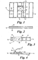
- a typical conventional timber frame panel 10 is made up of vertical studding 12 connected at the lower end to a sole plate 14 and at the upper end to a top plate 16. Generally, the spacing between the vertical studding 12 is uniform except where there is an aperture 17 for a door or window. In addition, adjacent vertical studs 12 may be interconnected by a noggin 18. This timber studding framework is sandwiched between an outer plywood sheathing 20 and an inner plasterboard skin 22 to provide a timber frame panel. During production, the internal cavities of the timber frame panel are filled with insulating material either in the form of quilts or batts, or by blowing fibres.
- a travelling applicator head of special design traverses the surface of the panel to blow fibre continuously into a running chamber as the applicator head moves smoothly over the surface.
- the applicator head 24 comprises a generally flat cover plate 26 which is wide enough to fill one channel between two timber studs (typically spaced at 600 mm).
- the filling head is advanced in the direction of the arrow A whilst a mixture of air and fibre is blown through the filling chamber 28.
- the cover plate has an extended leading edge 30 which effectively closes the leading edge of the cavity into which the fibre is blown under pressure. Because of the direction of movement, the fibre at the trailing edge is already packed to a stable state and therefore the trailing edge can be much shorter.
- the length of the leading edge is such that there is sufficient friction provided between the surfaces of the underlying sheathing panel 20 and the underside of the leading edge 30 to resist the blowing pressure which might otherwise force fibre out from below the plate 26, thus preventing a complete and well-compressed fill.
- this dimension is typically about 5-10 times the depth to be filled.
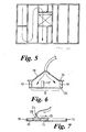
- the filling chamber 28 may take many forms but in this example takes a hollow conical shape, as seen in figures 4 and 6. This shape effectively spreads the pressure evenly across the width of the channel to be filled, giving a correspondingly even density which cannot be obtained with the earlier drill and fill processes. Additionally, the chamber has the great advantage of allowing complex sections to be filled, where for example intermediate studs 121 are encountered as in the channel or recess identified at 32 on Figure 1. As seen in Figure 6, it can be seen that the chamber allows fibre to flow to each side of the intermediate stud 12 1 whereas, if there were no filling chamber and a simple access hole, the channel to one side of the intermediate stud would not be filled.
- the filling head is traversed in serpentine fashion along adjacent recesses or channels and filling proceeds over the entire panel, irrespective of the position of additional timbers, whether they be at right angles or parallel to the direction of travel.
- Any areas designated as windows 17 or doors i.e. sections not to be filled with insulation) can be fitted with temporary blanking plates over which the filling head 28 may traverse without obstruction, but without the ingress of fibre which continues to be held under pressure within the filling chamber 28.
- the fibre fill may be visually inspected for completeness of fill, density etc before the inner plasterboard skin 22 is applied to complete the panel.
- the panel is initially part-formed with the outer skin and the skeletal framework, it could of course be partly formed with the inner skin and the skeletal framework. It is of course preferred to keep the panel horizontal during the filling process although we do not exclude the possibility of the panel being oriented differently.
- the head has a width slightly larger than the typical horizontal spacing of the timber studs 12, and traverses the recesses one by one moving generally longitudinally with respect to each recess.
- FIG. 7 a second embodiment of filling head 24 is illustrated in which the leading edge of the cover plate is foreshortened and a cavity closing piece or weir 34 projects downwardly from the underside of the cover plate to retain fibre within the channel.
- This design is intended for the special case where it is known that channels will always be of similar width with no obstructions or intermediate timbers.
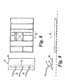
- FIG. 8 there is shown an alternative fixed filling head 44 which spans the whole side of the timber frame panel and under which a panel sweeps in a single direction relative as shown by the arrow B, to enable the whole panel to be passed at a controlled speed under the head.
- This arrangement is particularly preferred for semi-automated production of timber frame panels because movement in a single direction only is required, and a wide variety of different designs of the panel can be filled.
- the head 44 includes a cover plate 26, and an elongate filling chamber 48 of generally trihedral cross section as seen more clearly in Figure 9.
- the filling chamber 48 is supplied with a mixture of air and fibres through the hoses 46.
- the head 44 fills the panel one channel at a time but it fills across the channel rather than along its length.
- the chamber 48 can be of various designs but a trihedron as shown has been found to be effective in providing a good flow and even dispersion without resulting in blockages within the chamber.
- Figures 10 and 11 it is found that the above arrangements may be enhanced by using methods which help to "fluidise" the fibre within the filling chamber 28, thus improving the ability of the fibre to flow willingly and easily even into very small cavities.
- two methods which may be used either separately or in combination namely mechanical agitation and air pulsing.
- a mechanical agitator is disposed within the filling chamber 28 or 48 and comprises a blade 50 mounted on a vertical shaft which is rotated within the chamber further to disperse and fluidise the fibres in the airflow.
- a series of these devices could be used in the embodiment of Figures 8 and 9.
- the arrangement of Figures 8 and 9 may incorporate a mechanical agitator as shown in Figure 12.
- a horizontal elongate rod 52 is rotatably and axially moveable within the filling chamber 48.
- the agitator includes a series of paddles 54 at spaced intervals. In use the rod 52 is rotated and reciprocated back and forth to agitate fibre in the chamber.
- the air pulsing may be achieved by suddenly and periodically cutting off the pressure exerted by the blowing machine on the chamber, or by applying a pulse of compressed air to the chamber to make use of the "reverse jet" principle.
- each filling point may be pulsed in turn in order to encourage the fibre to flow back and forth along the length of the chamber.
- the filling head 54 is similar to that shown in Figures 8 and 9 and is mounted above a workpiece table 56 having a drive roller 58 for driving an open-topped timber frame panel 59 to be filled.
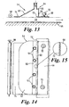
- the filling head 54 has a vertical trailing wall 60, a leading wall 62 inclined in this example at about 60° to the trailing wall 60 and a number of fibre feed inlets 64 in the roof 66. It is emphasised that the angles given here are by way of example, relating to one particular implementation, and that different angles may be used.
- the overall requirement is that the walls should be sufficiently divergent so that the compressed fibre in the filing head does not block and remains free to flow into the panel at all times when the space below is not yet fully filled. In the particular example of Figure 13, it has been much found that angles in excess of 62° may make the head too divergent and adversely alter fibre distribution, and that angles much below about 45° may increase the risk of the head becoming blocked with fibres.
- a screeding plate 68 Adjacent the lower edge of the trailing wall 60 is a screeding plate 68 which is moveably mounted by a cam arrangement 70 which is driven to oscillate the screeding plate 68 in the horizontal plane with the leading edge protruding into the filling head 54.
- This provides a number of important advantages. It serves to distribute and agitate the air/fibre mix within the filling chamber 54.
- the plate 68 has a serrated leading edge 72 which serves to cut through the mass of fibres with a bread knife effect.
- the lower surface of the screeding plate 68 applies a smoothing effect to the fibrous insulating material once it has been delivered into the panel 59.
- the screeding plate 68 also provides a sealing effect.
- cover plate 74 which, in conjunction with the fibrous material and the panel framework, retains fibre in the panel and provides a sealing action.
- a scrub roller 76 is driven contrary to the direction of movement of the panel as it is advanced under the filling head 54 to scrub the surface of the insulating material to level it, with suitable vacuum means (not shown) to remove surplus material.
- the roller may be driven in the same sense as the panel to roll the surface.
- a moving conveyer belt arrangement 78 moves at the same speed as the panel to retain and smooth the surface of the insulating material.
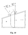
- FIGs 18 and 19 it is common to encounter wall panels in which the sides are not parallel, for example gable wall sections.
- the movable plate 80 is kept in contact with the non-parallel edge by either springs 82 or pneumatic pressure or other means.
- the wheels 76 mounted to the plate follow the movement of the non-parallel edge exactly to ensure that the blanking plate is at all times correctly positioned.
- Figures 19 (a) to (d) show how the position of the plate 74 changes with different shapes of panel to allow all types to be passed under the filling head without loss of insulation.
- the pressure in the feed inlets 62 may be monitored for process control. For example, at commencement of filling of each empty panel section, the pressure drops and the traverse of the panel can be slowed or stopped until pressure increases, indicating that that section is full. Additionally or alternatively, when pressure reaches a pre-set level in any single hose, the air intake to that hose can be partially or wholly shut off in order to prevent excessive pressure in one area, or the pressure across all the filling points in the panel can be balanced continuously to provide a consistent fill.
Landscapes
- Engineering & Computer Science (AREA)
- Architecture (AREA)
- Civil Engineering (AREA)
- Structural Engineering (AREA)
- Physics & Mathematics (AREA)
- Electromagnetism (AREA)
- Acoustics & Sound (AREA)
- Moulds For Moulding Plastics Or The Like (AREA)
- Stringed Musical Instruments (AREA)
- Telephone Function (AREA)
- Vessels And Coating Films For Discharge Lamps (AREA)
- Manipulator (AREA)
- Container, Conveyance, Adherence, Positioning, Of Wafer (AREA)
- Building Environments (AREA)
Abstract
Description
- This invention relates to methods and apparatus for introducing air-entrainable material such as, for example, insulating material, into an open recess or channel and to products so formed. In particular, but not exclusively, the invention relates to methods and apparatus for introducing insulating fibre material such as fibrous or foam material into an open frame element such as a timber frame.
- Houses may be built using a timber frame construction method in which timber-framed panels are manufactured in a factory and then erected on site. As shown in Figure 1 of the accompanying drawings, a typical panel comprises a timber "studding" framework of elements typically 90 mm x 40 mm with a plywood sheathing board forming the external skin and plasterboard the internal skin. Alternative materials may sometimes be used, and a polythene vapour control layer may be included under the plasterboard. The vertical studding is normally placed at fixed modular distances, for example 600 mm, but as seen in Figure 1, design considerations often result in complex arrangements of the studs, e.g. where a door or window is included. The panels are normally insulated by pressing mineral fibre "quilt" or "batts" between the studding, prior to fixing the plasterboard.
- Use of mineral fibre quilt or batts requires cutting the material to size and fitting in the recesses and this is time consuming and awkward and special precautions may need to be taken with the mineral fibre.
- As an alternative to mineral fibre quilt, it is possible to use a loose-fill insulation of fibres such as mineral fibre or, preferably, cellulose fibre. In this method, the fibres are compressed into the space so as to give a stable fill which will resist settlement over time. Previous methods of insulating panels in this way have included drilling holes in the top or bottom stud of the panel, between each pair of vertical studs, and inserting a lance through the hole through which fibre is blown. The lance is fully inserted and then gradually withdrawn as filling proceeds. Alternatively holes may be drilled in either the plywood or plasterboard skins and then a nozzle can be inserted through the hole through which the fibre is blown.
- There are many disadvantages involved with these methods. The panels are damaged, which is not easy to make good. It is difficult to provide an even fill without localised areas of high density and of low density (which may give rise to settlement of the fibre over time). The complexity of many panels can make the methods difficult or impossible to employ. Since the filling is being done "blind" through a single aperture into each recess, it is not possible to make a visual check to ensure that the filling is complete and uniform. US-A-2989790 discloses a method for filling wall cavities with insulating material. In this method the wall cavity is vertical and a mesh is temporarily attached between studs to define a cavity which is filled by lowering a filling head to the bottom of the cavity and then blowing material through the head whilst moving the head back and forth and up and down to tamp the discharged insulating material.
- We have developed a system for introducing or packing insulating material into the recesses of a timber frame panel, which overcomes or mitigates at least some of the above disadvantages.
- Accordingly, in one aspect of this invention, there is provided a method of introducing air-entrainable material into an open channel defined by a base and two spaced longitudinal side walls, the side walls terminating in respective generally co-planar surface regions defining the top of the channel, wherein said method includes applying to said channel a filling head dimensioned to span at least one of the width and length of the channel and to lie adjacent the top of the channel, said filling head having a cover plate associated therewith, thereby temporarily to cover said channel locally to define a local cavity, delivering into said cavity a blown mixture of air and air-entrainable material while substantially reducing or preventing leakage of the air-entrainable material, and effecting relative movement of said channel relative to said filling head, progressively to fill said channel.
- The terms "upwards", "downwards", "transversely" etc. as used herein refer to the various items when the recess or channel extends generally horizontally, and the terms "leading" and "trailing" refer to the direction of relative movement of the filling head and the channel.
- In one arrangement, where said filling head is disposed to span the width of the channel, said method may include effecting relative movement of said filling head longitudinally along said channel to fill said channel, or a plurality thereof.
- Various filling movements are possible, depending on the shape and configuration of the recesses or channels and the size of the cover plate means. Thus, where a series of elongate channels of generally constant width are to be filled with fibre, the cover plate means and said point of delivery may be moved along each said channel to fill one channel or recess at a time, with the width of the cover plate means being sufficient to extend between opposite sides of said channel.
- Alternatively, in a particularly preferred embodiment for filling a plurality of side by side longitudinal channels, a much larger cover plate may be used, long enough to span the entire length of at least one of the channels. Here the cover plate means and the point of delivery may be held stationary whilst the panel is moved beneath them in a single pass so that the channels move transversely in succession under the cover plate.
- The step of substantially preventing or reducing leakage of insulating or other air-entrainable material from said recess or channel may be achieved in a variety of ways. As the cover plate means moves in a given direction relative to a recess or channel, the insulating or other air-entrainable material at the trailing edge of the cover plate (in the sense of said movement direction) will already have been compressed by the delivery of material and this will prevent or reduce leakage from the trailing edge. However, at the leading edge of the cover plate means, where the bulk of the filling has yet to form, it is also necessary to prevent or reduce leakage. In one example, the leakage prevention means comprises an extended leading edge for the cover plate means which is selected with regard to the other operating parameters such as the air velocity, fibre size, filling depth, size and effective friction coefficient of the cover plate means etc, so that the accumulated friction applied both by the leading edge portion of the cover plate means and the opposing base and sides of the recess or channel is sufficient substantially to prevent or reduce leakage of material. The length of the leading edge portion of the plate required for any particular application may easily be determined by one skilled in the art using routine experimentation.
- Alternatively, in one special case, where the filling head is moved longitudinally with respect to the channels or recesses, and it is known that the channels or recesses are of substantially the same width and that there are no obstructions or intermediate timbers above a pre-set height in the channel or recess, the cover plate means may be provided with a downwardly projecting wall for retaining insulating material within said recess or channel.
- Preferably, a screeding plate is disposed aft of the filling head in the sense of the relative movement thereof relation to the channels and is moved or oscillated relative to the filling head, over the surface of a filled channel to smooth the surface thereof, and to agitate or disturb the air-entrainable material within said filling head.
- The delivery pressure of the blown mixture may be monitored, and the speed of relative movement of the filling head relative to said channel controlled in accordance therewith.
- Likewise, the delivery pressure of the blown mixture may be monitored and the pressure of the air inlet to the filling head controlled in accordance with the monitored delivery pressure to maintain it below a preset level.
- Preferably the cover plate means and said point of delivery are incorporated in an applicator head means, which provides a filling chamber, for example of generally conical or trihedral shape which allows the insulating or other air-entrainable material to flow across the whole width of the channel or recess.
- Preferably, the insulating or other air-entrainable material is agitated prior to or adjacent said delivery point.
- In a further aspect of this invention there is provided a method of producing an insulated panel, which comprises providing a framework which is closed on one side of the frame by one orimore skin means to provide an open-topped framework panel, having a generally horizontal array of open channels separated by respective frame members, using a method as defined above to introduce insulating material into one or more of said channels, and then securing one or more skin elements to the other side of said framework to close said recesses and produce an insulated panel.
- In yet another aspect of this invention, there is provided apparatus for use in a method of introducing air-entrainable material to an open channel as described above, said apparatus comprising a filling head having an inlet for receiving a mixture of air and air-entrainable material, a filling chamber of divergent form, and a cover plate extending transversely thereof, wherein the cover plate defines a continuous co-planar peripheral region adapted in use to engage material delivered through said filling head, and said cover plate is adapted in use to span at least one of the width and the length of the channel and to prevent or reduce leakage of air-entrainable material from said channel, the apparatus further including a workpiece support for supporting a panel comprising the channel below said filling head, and traverse means for moving said panel with respect to said filling head.
- Preferably, said means for preventing or reducing comprises an extended portion of said cover plate means of length such that the friction accumulated between said extended portion and said material in use is sufficient to prevent or reduce leakage.
- Alternatively, said means for preventing or reducing leakage may comprise a weir or blocking plate means projecting from said one surface of said cover plate means into said recess or channel in use.
- Said discharge means preferably comprises a filling chamber, typically of conical or polyhedral form open to said one side of said cover plate means for receiving said mixture and discharging it across at least a substantial portion of the width of the recess or channel.
- The filling head preferably comprises a trailing wall extending generally vertically and a leading wall inclined at an acute angle to said trailing wall. The leading wall may be inclined at an angle of between 45° and 65° to said leading wall, and more preferably at an angle of about 60° to said leading wall.
- The filling head may comprise a plurality of feed inlets disposed along the length of the filling head with the feed inlets preferably being disposed in an upper wall or roof of said filling head.
- The apparatus may further include means for agitating or disturbing said air-entrainable material within said filling chamber, said means for agitating comprising an agitating member movably mounted adjacent the trailing region of said filling chamber and projecting into said chamber, and drive means for moving said agitating member. The means for agitating may further include a screeding plate having a leading edge region which projects into said filling chamber and defines a lower surface for screeding the surface of air-entrainable material in said panel.
- The apparatus may also include means responsive to the delivery pressure to the filling head to control the rate of movement of said traverse means in accordance therewith.
- Where the apparatus is intended to allow filling of panels whose dimension in the direction parallel to the longitudinal axis of the filling head varies along the length of the panels, it may include a blanking means movably associated with the underside of said filling head, and biased into engagement with an edge of said panel, whereby the longitudinal dimension of the effective discharge aperture defined by the open end of the filling chamber is varied in accordance with the dimension of the panel.
- The apparatus may include finishing means disposed aft of the filling head to finish the surface of the air-entrainable material in the panel; the finishing means may comprise at least one of a rotatable roller and a moving belt moving in the same sense as said panel.
- The invention may be performed in various ways, and various embodiments thereof will now be described in detail, reference being made to the accompanying drawings, in which:-
- Figure 1 is a side elevation of the skeletal framework studding of a typical conventional timber frame panel;
- Figure 2 is an underneath plan view of the timber frame panel of Figure 1;
- Figure 3 is a schematic top plan view of a first embodiment of filling head in accordance with a further aspect of this invention applied to fill an elongate recess;
- Figure 4 is a sectional view through the first embodiment of filling head of this invention illustrated in Figure 3;
- Figure 5 is a schematic view illustrating one possible path for filling a timber frame panel of the type shown in Figure 1;
- Figure 6 is a transverse section view, on an enlarged scale, of the first embodiment of filling head;
- Figure 7 is a section view through a second embodiment of filling head in accordance with the invention, intended for use with panels made up of a series of substantially unobstructed recesses of generally uniform width;
- Figure 8 is a view from above of a third embodiment of an extended filling head for filling a timber frame panel in a single uni-directional sweep in a direction transverse to the longitudinal channels of this panel;
- Figure 9 is a side view of the arrangement of Figure 8;
- Figures 10 and 11 are schematic section and underneath plan views respectively of a first form of agitation mechanism for a filling head of this invention;
- Figure 12 is a schematic underneath plan view of an embodiment of agitation mechanism for use with embodiments of extended filling head of the type shown in Figures 8 and 9;
- Figure 13 is a schematic transverse section view through a fourth embodiment of an extended filling head for filling a timber frame panel in a single uni-directional sweep in a direction transverse to the longitudinal channels of the panel;
- Figure 14 is a schematic plan view of the fourth embodiment of filling head;
- Figure 15 is a detailed view of the leading edge of the screeding plate used in Figures 14 and 15;
- Figure 16 is a schematic transverse section view of the fourth embodiment of this invention fitted with a finishing roller;
- Figure 17 is a schematic transverse section view of the fourth embodiment of this invention fitted with a finishing belt;
- Figure 18 is a plan view of a fifth embodiment of this invention fitted with a moveable blanking plate, and
- Figures 19(a) to (d) are plan views showing the orientation of the blanking plate with respect to the filling head for a variety of different shapes of panel workpiece.
-
- Referring initially to Figures 1 and 2, a typical conventional
timber frame panel 10 is made up of vertical studding 12 connected at the lower end to asole plate 14 and at the upper end to atop plate 16. Generally, the spacing between the vertical studding 12 is uniform except where there is anaperture 17 for a door or window. In addition, adjacentvertical studs 12 may be interconnected by anoggin 18. This timber studding framework is sandwiched between anouter plywood sheathing 20 and aninner plasterboard skin 22 to provide a timber frame panel. During production, the internal cavities of the timber frame panel are filled with insulating material either in the form of quilts or batts, or by blowing fibres. - In the embodiments to be described below, before the final inner (or outer) skin is applied, a travelling applicator head of special design traverses the surface of the panel to blow fibre continuously into a running chamber as the applicator head moves smoothly over the surface.
- Referring now to Figure 3, in its simplest form, the
applicator head 24 comprises a generallyflat cover plate 26 which is wide enough to fill one channel between two timber studs (typically spaced at 600 mm). In order to fill the channel or recess between the two timber studs, the filling head is advanced in the direction of the arrow A whilst a mixture of air and fibre is blown through the fillingchamber 28. As will be seen from Figures 3 and 4, the cover plate has an extended leadingedge 30 which effectively closes the leading edge of the cavity into which the fibre is blown under pressure. Because of the direction of movement, the fibre at the trailing edge is already packed to a stable state and therefore the trailing edge can be much shorter. The length of the leading edge is such that there is sufficient friction provided between the surfaces of theunderlying sheathing panel 20 and the underside of the leadingedge 30 to resist the blowing pressure which might otherwise force fibre out from below theplate 26, thus preventing a complete and well-compressed fill. We have found that this dimension is typically about 5-10 times the depth to be filled. - The filling
chamber 28 may take many forms but in this example takes a hollow conical shape, as seen in figures 4 and 6. This shape effectively spreads the pressure evenly across the width of the channel to be filled, giving a correspondingly even density which cannot be obtained with the earlier drill and fill processes. Additionally, the chamber has the great advantage of allowing complex sections to be filled, where for exampleintermediate studs 121 are encountered as in the channel or recess identified at 32 on Figure 1. As seen in Figure 6, it can be seen that the chamber allows fibre to flow to each side of theintermediate stud 121 whereas, if there were no filling chamber and a simple access hole, the channel to one side of the intermediate stud would not be filled. - As seen in Figure 5, the filling head is traversed in serpentine fashion along adjacent recesses or channels and filling proceeds over the entire panel, irrespective of the position of additional timbers, whether they be at right angles or parallel to the direction of travel. Any areas designated as
windows 17 or doors (i.e. sections not to be filled with insulation) can be fitted with temporary blanking plates over which the fillinghead 28 may traverse without obstruction, but without the ingress of fibre which continues to be held under pressure within the fillingchamber 28. - Once the filling
head 24 has traversed the entire panel, the fibre fill may be visually inspected for completeness of fill, density etc before theinner plasterboard skin 22 is applied to complete the panel. - Although in this example the panel is initially part-formed with the outer skin and the skeletal framework, it could of course be partly formed with the inner skin and the skeletal framework. It is of course preferred to keep the panel horizontal during the filling process although we do not exclude the possibility of the panel being oriented differently.
- In the above embodiment, the head has a width slightly larger than the typical horizontal spacing of the
timber studs 12, and traverses the recesses one by one moving generally longitudinally with respect to each recess. - Referring now to Figure 7, a second embodiment of filling
head 24 is illustrated in which the leading edge of the cover plate is foreshortened and a cavity closing piece orweir 34 projects downwardly from the underside of the cover plate to retain fibre within the channel. This design is intended for the special case where it is known that channels will always be of similar width with no obstructions or intermediate timbers. - Referring now to the arrangement of Figures 8 and 9, there is shown an alternative fixed filling
head 44 which spans the whole side of the timber frame panel and under which a panel sweeps in a single direction relative as shown by the arrow B, to enable the whole panel to be passed at a controlled speed under the head. This arrangement is particularly preferred for semi-automated production of timber frame panels because movement in a single direction only is required, and a wide variety of different designs of the panel can be filled. Here thehead 44 includes acover plate 26, and an elongate fillingchamber 48 of generally trihedral cross section as seen more clearly in Figure 9. The fillingchamber 48 is supplied with a mixture of air and fibres through thehoses 46. In this arrangement, thehead 44 fills the panel one channel at a time but it fills across the channel rather than along its length. Thechamber 48 can be of various designs but a trihedron as shown has been found to be effective in providing a good flow and even dispersion without resulting in blockages within the chamber. - Referring now to Figures 10 and 11, it is found that the above arrangements may be enhanced by using methods which help to "fluidise" the fibre within the filling
chamber 28, thus improving the ability of the fibre to flow willingly and easily even into very small cavities. We have devised two methods which may be used either separately or in combination, namely mechanical agitation and air pulsing. In Figures 10 and 11, a mechanical agitator is disposed within the fillingchamber blade 50 mounted on a vertical shaft which is rotated within the chamber further to disperse and fluidise the fibres in the airflow. A series of these devices could be used in the embodiment of Figures 8 and 9. Alternatively, the arrangement of Figures 8 and 9 may incorporate a mechanical agitator as shown in Figure 12. Here a horizontalelongate rod 52 is rotatably and axially moveable within the fillingchamber 48. The agitator includes a series ofpaddles 54 at spaced intervals. In use therod 52 is rotated and reciprocated back and forth to agitate fibre in the chamber. - The air pulsing may be achieved by suddenly and periodically cutting off the pressure exerted by the blowing machine on the chamber, or by applying a pulse of compressed air to the chamber to make use of the "reverse jet" principle. In the case of the arrangement of Figures 8 and 9, each filling point may be pulsed in turn in order to encourage the fibre to flow back and forth along the length of the chamber.
- Referring now to Figure 13, in this embodiment the filling
head 54 is similar to that shown in Figures 8 and 9 and is mounted above a workpiece table 56 having adrive roller 58 for driving an open-toppedtimber frame panel 59 to be filled. The fillinghead 54 has a vertical trailingwall 60, a leadingwall 62 inclined in this example at about 60° to the trailingwall 60 and a number offibre feed inlets 64 in theroof 66. It is emphasised that the angles given here are by way of example, relating to one particular implementation, and that different angles may be used. The overall requirement is that the walls should be sufficiently divergent so that the compressed fibre in the filing head does not block and remains free to flow into the panel at all times when the space below is not yet fully filled. In the particular example of Figure 13, it has been much found that angles in excess of 62° may make the head too divergent and adversely alter fibre distribution, and that angles much below about 45° may increase the risk of the head becoming blocked with fibres. - Adjacent the lower edge of the trailing
wall 60 is ascreeding plate 68 which is moveably mounted by acam arrangement 70 which is driven to oscillate thescreeding plate 68 in the horizontal plane with the leading edge protruding into the fillinghead 54. This provides a number of important advantages. It serves to distribute and agitate the air/fibre mix within the fillingchamber 54. Theplate 68 has a serratedleading edge 72 which serves to cut through the mass of fibres with a bread knife effect. The lower surface of thescreeding plate 68 applies a smoothing effect to the fibrous insulating material once it has been delivered into thepanel 59. Thescreeding plate 68 also provides a sealing effect. - At the leading edge of the filling head is a
cover plate 74 which, in conjunction with the fibrous material and the panel framework, retains fibre in the panel and provides a sealing action. - Referring now to Figures 16 and 17, there are shown two different optional finishing arrangements which may be beneficial depending on the nature of the fibres and the particular intended application. In Figure 16 a
scrub roller 76 is driven contrary to the direction of movement of the panel as it is advanced under the fillinghead 54 to scrub the surface of the insulating material to level it, with suitable vacuum means (not shown) to remove surplus material. Alternatively the roller may be driven in the same sense as the panel to roll the surface. - In Figure 17, a moving
conveyer belt arrangement 78 moves at the same speed as the panel to retain and smooth the surface of the insulating material. - Referring now to Figures 18 and 19, it is common to encounter wall panels in which the sides are not parallel, for example gable wall sections. In this case it is again possible to use blanking plates to 'square up' the panel, but an alternative is shown in these Figures where a blanking
plate 80 fixed under the fillinghead 54, and in close contact with it, moves in and out as required to ensure that any section of the filling head not directly over the panel will be blanked off to prevent the escape of the insulation. In Figure 18, themovable plate 80 is kept in contact with the non-parallel edge by eithersprings 82 or pneumatic pressure or other means. Thewheels 76 mounted to the plate follow the movement of the non-parallel edge exactly to ensure that the blanking plate is at all times correctly positioned. - Figures 19 (a) to (d) show how the position of the
plate 74 changes with different shapes of panel to allow all types to be passed under the filling head without loss of insulation. - In addition, the pressure in the
feed inlets 62 may be monitored for process control. For example, at commencement of filling of each empty panel section, the pressure drops and the traverse of the panel can be slowed or stopped until pressure increases, indicating that that section is full. Additionally or alternatively, when pressure reaches a pre-set level in any single hose, the air intake to that hose can be partially or wholly shut off in order to prevent excessive pressure in one area, or the pressure across all the filling points in the panel can be balanced continuously to provide a consistent fill.
Claims (24)
- A method of introducing air-entrainable material into an open channel defined by a base (20) and two spaced longitudinal side walls (12) the side walls (12) terminating in respective generally co-planar surface regions defining the top of the channel, characterised in that said method includes applying to said channel a filling head (24;44;54) dimensioned to span at least one of the width and length of the channel and to lie adjacent the top of the channel, said filling head (24) having a cover plate (26) associated therewith, thereby temporarily to cover said channel locally to define a local cavity, delivering into said cavity a blown mixture of air and air-entrainable material while substantially reducing or preventing leakage of the air-entrainable material, and effecting relative movement of said channel relative to said filling head (24), progressively to fill said channel.
- A method according to Claim 1, wherein said filling head (24) is disposed to span the width of the channel, and is moved longitudinally with respect to said channel.
- A method according to Claim 1, for introducing air-entrainable material into a plurality of longitudinal channels arranged side by side, wherein said filling head (44;54) is disposed to span the length of at least one of said channels and said plurality of channels is moved relative to said filling head (44;54) in a direction perpendicular to the length of the channels, to cause said channels to be filled with said air-entrainable material.
- A method according to Claim 3, wherein said filling head (44;54) remains stationary whilst said plurality of channels is moved with respect thereto.
- A method according to any of the preceding claims, wherein said filling head (24;44;54) includes an extended leading edge (26;74) in the sense of the movement of the filling head (24;44;54) relative to the channel, whereby the extended area of contact between the air-entrainable material in said channel and said extended leading edge (26) is sufficient to substantially reduce or prevent leakage in that direction.
- A method according to any of Claims 1 to 3, for filling a recess of substantially constant width and depth, wherein the leading edge (26) of said filling head (24) includes a downwardly projecting retaining plate (34) which fits within said channel.
- A method according to any of Claims 1 to 5, in which a screeding plate (68) is disposed aft of the filling head (54) in the sense of the relative movement thereof relation to the channel, and is moved or oscillated relative to the filling head (54) over the surface of a filled channel to smooth the surface thereof, and to agitate or disturb the air-entrainable material within said filling head (54).
- A method according to any of the preceding claims, wherein the delivery pressure of the blown mixture is monitored, and the speed of relative movement of the filling head (24;44;54) relative to said channel is controlled in accordance therewith.
- A method according to any of the preceding claims, wherein the delivery pressure of the blown mixture is monitored and the pressure of the air inlet to the filling head (24;44;54) is controlled in accordance with the monitored delivery pressure to maintain it below a preset level.
- A method of producing an insulated panel which comprises providing an open topped framework panel, filling said panel with insulating material using a method according to any of the preceding claims, and applying a skin element to close the panel.
- Apparatus for use in a method of introducing air-entrainable material to an open channel according to any of the preceding claims, said apparatus comprising a filling head (24;44;54) having an inlet for receiving a mixture of air and air-entrainable material, a filling chamber (28) of divergent form, and a cover plate (26) extending transversely thereof, characterised in that the cover plate (26) defines a continuous co-planar peripheral region adapted in use to engage the material delivered through said filling head and said cover plate (26) is adapted in use to span at least one of the width and the length of the channel and to prevent or reduce leakage of air-entrainable material from said channel, and in that said apparatus includes a workpiece support (56) for supporting a panel comprising the said channel below said filling head (64), and traverse means for moving said panel with respect to said filling head (64).
- Apparatus according to Claim 11, wherein said filling chamber (28) has a generally conical inner profile.
- Apparatus according to Claim 11 or Claim 12, wherein said filling head (24;44;54) is elongate, with said filling chamber (28) being polyhedral in transverse cross-section.
- Apparatus according to any one of Claims 11 to 13, wherein said filling head (24) comprises a trailing wall (60) extending generally vertically and a leading wall (62) inclined at an acute angle to said trailing wall (60).
- Apparatus according to Claim 14, wherein said leading wall (62) is inclined at an angle of between 45° and 65° to said leading wall (60).
- Apparatus according to Claim 15, wherein said leading wall (62) is inclined at an angle of about 60° to said leading wall (60).
- Apparatus according to any of Claims 11 to 16, wherein said filling head (24;44;54) comprises a plurality of feed inlets disposed along the length of the filling head.
- Apparatus according to Claim 17, wherein the feed inlets (64) are disposed in an upper wall or roof of said filling head (54).
- Apparatus according to any of Claims 11 to 18, further including means for agitating or disturbing said air entrainable material within said filling chamber (28), said means for agitating comprising an agitating member (68) movably mounted adjacent the trailing region of said filling chamber (64) and projecting into said chamber, and drive means (70) for moving said agitating member (68).
- Apparatus according to Claim 19, wherein said means for agitating further includes a screeding plate (68) having a leading edge region (72) which projects into said filling chamber (64) and defines a lower surface for screeding the surface of air-entrainable material in said panel.
- Apparatus according to any of Claims 11 to 20, further including means responsive to the delivery pressure to the filling head (64) to control the rate of movement of said traverse means in accordance therewith.
- Apparatus according to any of Claims 11 to 21, adapted to allow filling of panels whose dimension in the direction parallel to the longitudinal axis of the filling head varies along the length of the panels, which includes a blanking means (80) movably associated with the underside of said filling head (64), and biased into engagement with an edge of said panel, whereby the longitudinal dimension of the effective discharge aperture defined by the open end of the filling chamber is varied in accordance with the dimension of the panel.
- Apparatus according to any of Claims 11 to 22, which includes finishing means (58) disposed aft of the filling head (54) to finish the surface of the air-entrainable material in the panel.
- Apparatus according to Claim 23, wherein the finishing means comprises at least one of a rotatable roller and a moving belt moving in the same sense as said panel.
Applications Claiming Priority (4)
| Application Number | Priority Date | Filing Date | Title |
|---|---|---|---|
| GB9623201 | 1996-11-07 | ||
| GBGB9623201.2A GB9623201D0 (en) | 1996-11-07 | 1996-11-07 | Methods and apparatus for introducing air-entrainable material into a channel or recess |
| GBGB9708117.8A GB9708117D0 (en) | 1996-11-07 | 1997-04-22 | Methods and apparatus for introducing air-entrainable material into a chanel or recess |
| GB9708117 | 1997-04-22 |
Publications (3)
| Publication Number | Publication Date |
|---|---|
| EP0841444A2 EP0841444A2 (en) | 1998-05-13 |
| EP0841444A3 EP0841444A3 (en) | 1998-11-18 |
| EP0841444B1 true EP0841444B1 (en) | 2005-09-07 |
Family
ID=26310353
Family Applications (1)
| Application Number | Title | Priority Date | Filing Date |
|---|---|---|---|
| EP97308886A Expired - Lifetime EP0841444B1 (en) | 1996-11-07 | 1997-11-05 | Methods and apparatus for introducing air-entrainable material into a channel or recess |
Country Status (4)
| Country | Link |
|---|---|
| EP (1) | EP0841444B1 (en) |
| AT (1) | ATE304099T1 (en) |
| DE (1) | DE69734137T2 (en) |
| GB (1) | GB9708117D0 (en) |
Cited By (2)
| Publication number | Priority date | Publication date | Assignee | Title |
|---|---|---|---|---|
| EP2333198A1 (en) | 2009-12-03 | 2011-06-15 | isofloc AG | Method and device for blowing insulation into insulation chambers |
| DE102021131257A1 (en) | 2021-11-29 | 2023-06-01 | GEKO Maschinenbau GmbH | Device for introducing insulating material into an insulating material chamber |
Families Citing this family (2)
| Publication number | Priority date | Publication date | Assignee | Title |
|---|---|---|---|---|
| DE20106489U1 (en) * | 2001-04-14 | 2001-09-06 | Gleixner, Markus, 93482 Pemfling | Device for blowing in insulation material in the insulation chamber of wall, ceiling or roof elements |
| EP3246490B1 (en) * | 2016-05-20 | 2023-11-01 | isofloc AG | Method and device for injecting injected material into insulating material chambers of components |
Family Cites Families (3)
| Publication number | Priority date | Publication date | Assignee | Title |
|---|---|---|---|---|
| US2989790A (en) * | 1957-06-10 | 1961-06-27 | Judd A Brown | Apparatus and method for applying and packing fibrous material |
| US4330921A (en) * | 1978-09-21 | 1982-05-25 | White Jr Olin N | Insulated wall sections and methods of and apparatus for prefabricating the same |
| US4829738A (en) * | 1987-04-02 | 1989-05-16 | Certainteed Corporation | Loose-fill cavity insulation by pneumatic injection |
-
1997
- 1997-04-22 GB GBGB9708117.8A patent/GB9708117D0/en active Pending
- 1997-11-05 EP EP97308886A patent/EP0841444B1/en not_active Expired - Lifetime
- 1997-11-05 AT AT97308886T patent/ATE304099T1/en not_active IP Right Cessation
- 1997-11-05 DE DE69734137T patent/DE69734137T2/en not_active Expired - Fee Related
Cited By (4)
| Publication number | Priority date | Publication date | Assignee | Title |
|---|---|---|---|---|
| EP2333198A1 (en) | 2009-12-03 | 2011-06-15 | isofloc AG | Method and device for blowing insulation into insulation chambers |
| DE202010018111U1 (en) | 2009-12-03 | 2014-02-17 | Isofloc Ag | Device for blowing insufflation insulation in insulation chambers |
| DE102021131257A1 (en) | 2021-11-29 | 2023-06-01 | GEKO Maschinenbau GmbH | Device for introducing insulating material into an insulating material chamber |
| DE102021131257B4 (en) | 2021-11-29 | 2024-01-25 | GEKO Maschinenbau GmbH | Device for introducing insulation material into an insulation chamber |
Also Published As
| Publication number | Publication date |
|---|---|
| GB9708117D0 (en) | 1997-06-11 |
| DE69734137D1 (en) | 2005-10-13 |
| DE69734137T2 (en) | 2006-06-22 |
| EP0841444A3 (en) | 1998-11-18 |
| ATE304099T1 (en) | 2005-09-15 |
| EP0841444A2 (en) | 1998-05-13 |
Similar Documents
| Publication | Publication Date | Title |
|---|---|---|
| FI71516B (en) | PROCEDURE FOR THE FRAMEWORK OF THE PLASTERING PLASTER | |
| EP0841444B1 (en) | Methods and apparatus for introducing air-entrainable material into a channel or recess | |
| US3446687A (en) | Apparatus for laminating and coating insulating panels | |
| US4158535A (en) | Generation of polyurethane foam | |
| US5858095A (en) | Shuttle cutoff for applying granules to an asphalt coated sheet | |
| US4280974A (en) | Process and apparatus for making a plurality of building modules having a foam core and a cementitious shell | |
| JPH04302660A (en) | Device for applying tile material onto building floor | |
| DE68908409T2 (en) | DEVICE AND METHOD FOR PRODUCING FIBER PANELS. | |
| EP1255001B1 (en) | Device and method for the blowing in of insulating material in hollows of wall, ceiling or roofing elements | |
| DE3612520A1 (en) | Process and device for producing panels or walls from a mixture containing a loam construction material and water | |
| EP0807235B1 (en) | Method and device for drying out buildings and/or fixed components | |
| EP0314874B1 (en) | Method for delivering a foamable mixture, especially a temperature insulation material, using a mixing head for at least two reactive components in a low-pressure method | |
| EP0221900B1 (en) | A method of breaking up bundles of adherent hard fibers and an oscillating screen | |
| EP0222096A1 (en) | Apparatus for transporting glass panes standing on edge | |
| DE3717216C2 (en) | ||
| EP0595287B1 (en) | Process for the production of semi-finished corner units of laminate | |
| US6974502B2 (en) | Coating chamber and templates to produce decorative mouldings | |
| DE3504104A1 (en) | HOLLOW BLOCK STONE AND METHOD AND DEVICE FOR ITS PRODUCTION | |
| EP0126370B1 (en) | Method of and apparatus for continuously producing foamed plastic webs | |
| EP0234048B1 (en) | Method and apparatus for manufacturing brick wall elements | |
| WO2005056341A1 (en) | Wear resistant and sound-insulating floor coating for a motor vehicle | |
| CN213449569U (en) | Mortar spreader | |
| DE102021131257B4 (en) | Device for introducing insulation material into an insulation chamber | |
| GB2301595A (en) | Vertical production of foamed polyurethane slab-stocks | |
| US4958935A (en) | Method of breaking up bundles of adherent hard fibers and an oscillating screen |
Legal Events
| Date | Code | Title | Description |
|---|---|---|---|
| PUAI | Public reference made under article 153(3) epc to a published international application that has entered the european phase |
Free format text: ORIGINAL CODE: 0009012 |
|
| AK | Designated contracting states |
Kind code of ref document: A2 Designated state(s): AT BE CH DE DK FI FR GB IE LI LU NL SE |
|
| AX | Request for extension of the european patent |
Free format text: AL;LT;LV;MK;RO;SI |
|
| PUAL | Search report despatched |
Free format text: ORIGINAL CODE: 0009013 |
|
| AK | Designated contracting states |
Kind code of ref document: A3 Designated state(s): AT BE CH DE DK ES FI FR GB GR IE IT LI LU MC NL PT SE |
|
| AX | Request for extension of the european patent |
Free format text: AL;LT;LV;MK;RO;SI |
|
| 17P | Request for examination filed |
Effective date: 19981019 |
|
| AKX | Designation fees paid |
Free format text: AT BE CH DE DK FI FR GB IE LI LU NL SE |
|
| 17Q | First examination report despatched |
Effective date: 20021030 |
|
| GRAP | Despatch of communication of intention to grant a patent |
Free format text: ORIGINAL CODE: EPIDOSNIGR1 |
|
| GRAS | Grant fee paid |
Free format text: ORIGINAL CODE: EPIDOSNIGR3 |
|
| GRAA | (expected) grant |
Free format text: ORIGINAL CODE: 0009210 |
|
| AK | Designated contracting states |
Kind code of ref document: B1 Designated state(s): AT BE CH DE DK FI FR GB IE LI LU NL SE |
|
| PG25 | Lapsed in a contracting state [announced via postgrant information from national office to epo] |
Ref country code: NL Free format text: LAPSE BECAUSE OF FAILURE TO SUBMIT A TRANSLATION OF THE DESCRIPTION OR TO PAY THE FEE WITHIN THE PRESCRIBED TIME-LIMIT Effective date: 20050907 Ref country code: LI Free format text: LAPSE BECAUSE OF FAILURE TO SUBMIT A TRANSLATION OF THE DESCRIPTION OR TO PAY THE FEE WITHIN THE PRESCRIBED TIME-LIMIT Effective date: 20050907 Ref country code: FI Free format text: LAPSE BECAUSE OF FAILURE TO SUBMIT A TRANSLATION OF THE DESCRIPTION OR TO PAY THE FEE WITHIN THE PRESCRIBED TIME-LIMIT Effective date: 20050907 Ref country code: CH Free format text: LAPSE BECAUSE OF FAILURE TO SUBMIT A TRANSLATION OF THE DESCRIPTION OR TO PAY THE FEE WITHIN THE PRESCRIBED TIME-LIMIT Effective date: 20050907 Ref country code: BE Free format text: LAPSE BECAUSE OF FAILURE TO SUBMIT A TRANSLATION OF THE DESCRIPTION OR TO PAY THE FEE WITHIN THE PRESCRIBED TIME-LIMIT Effective date: 20050907 Ref country code: AT Free format text: LAPSE BECAUSE OF FAILURE TO SUBMIT A TRANSLATION OF THE DESCRIPTION OR TO PAY THE FEE WITHIN THE PRESCRIBED TIME-LIMIT Effective date: 20050907 |
|
| REG | Reference to a national code |
Ref country code: GB Ref legal event code: FG4D |
|
| REG | Reference to a national code |
Ref country code: CH Ref legal event code: EP |
|
| REG | Reference to a national code |
Ref country code: IE Ref legal event code: FG4D |
|
| REF | Corresponds to: |
Ref document number: 69734137 Country of ref document: DE Date of ref document: 20051013 Kind code of ref document: P |
|
| PG25 | Lapsed in a contracting state [announced via postgrant information from national office to epo] |
Ref country code: LU Free format text: LAPSE BECAUSE OF NON-PAYMENT OF DUE FEES Effective date: 20051130 |
|
| PG25 | Lapsed in a contracting state [announced via postgrant information from national office to epo] |
Ref country code: DK Free format text: LAPSE BECAUSE OF FAILURE TO SUBMIT A TRANSLATION OF THE DESCRIPTION OR TO PAY THE FEE WITHIN THE PRESCRIBED TIME-LIMIT Effective date: 20051207 |
|
| REG | Reference to a national code |
Ref country code: SE Ref legal event code: TRGR |
|
| NLV1 | Nl: lapsed or annulled due to failure to fulfill the requirements of art. 29p and 29m of the patents act | ||
| REG | Reference to a national code |
Ref country code: CH Ref legal event code: PL |
|
| ET | Fr: translation filed | ||
| PLBE | No opposition filed within time limit |
Free format text: ORIGINAL CODE: 0009261 |
|
| STAA | Information on the status of an ep patent application or granted ep patent |
Free format text: STATUS: NO OPPOSITION FILED WITHIN TIME LIMIT |
|
| 26N | No opposition filed |
Effective date: 20060608 |
|
| PGFP | Annual fee paid to national office [announced via postgrant information from national office to epo] |
Ref country code: SE Payment date: 20071128 Year of fee payment: 11 |
|
| PGFP | Annual fee paid to national office [announced via postgrant information from national office to epo] |
Ref country code: GB Payment date: 20071128 Year of fee payment: 11 Ref country code: FR Payment date: 20071119 Year of fee payment: 11 |
|
| PGFP | Annual fee paid to national office [announced via postgrant information from national office to epo] |
Ref country code: DE Payment date: 20071221 Year of fee payment: 11 |
|
| EUG | Se: european patent has lapsed | ||
| GBPC | Gb: european patent ceased through non-payment of renewal fee |
Effective date: 20081105 |
|
| REG | Reference to a national code |
Ref country code: IE Ref legal event code: MM4A |
|
| PGFP | Annual fee paid to national office [announced via postgrant information from national office to epo] |
Ref country code: IE Payment date: 20071126 Year of fee payment: 11 |
|
| REG | Reference to a national code |
Ref country code: FR Ref legal event code: ST Effective date: 20090731 |
|
| PG25 | Lapsed in a contracting state [announced via postgrant information from national office to epo] |
Ref country code: IE Free format text: LAPSE BECAUSE OF NON-PAYMENT OF DUE FEES Effective date: 20081105 Ref country code: DE Free format text: LAPSE BECAUSE OF NON-PAYMENT OF DUE FEES Effective date: 20090603 |
|
| PG25 | Lapsed in a contracting state [announced via postgrant information from national office to epo] |
Ref country code: GB Free format text: LAPSE BECAUSE OF NON-PAYMENT OF DUE FEES Effective date: 20081105 |
|
| PG25 | Lapsed in a contracting state [announced via postgrant information from national office to epo] |
Ref country code: SE Free format text: LAPSE BECAUSE OF NON-PAYMENT OF DUE FEES Effective date: 20081106 |
|
| PG25 | Lapsed in a contracting state [announced via postgrant information from national office to epo] |
Ref country code: FR Free format text: LAPSE BECAUSE OF NON-PAYMENT OF DUE FEES Effective date: 20081130 |