EP0841362B1 - Electric field enhanced coalescence of silicone emulsions - Google Patents
Electric field enhanced coalescence of silicone emulsions Download PDFInfo
- Publication number
- EP0841362B1 EP0841362B1 EP97308866A EP97308866A EP0841362B1 EP 0841362 B1 EP0841362 B1 EP 0841362B1 EP 97308866 A EP97308866 A EP 97308866A EP 97308866 A EP97308866 A EP 97308866A EP 0841362 B1 EP0841362 B1 EP 0841362B1
- Authority
- EP
- European Patent Office
- Prior art keywords
- continuous phase
- process according
- phase
- electric field
- emulsion
- Prior art date
- Legal status (The legal status is an assumption and is not a legal conclusion. Google has not performed a legal analysis and makes no representation as to the accuracy of the status listed.)
- Expired - Lifetime
Links
Images

Classifications
-
- C—CHEMISTRY; METALLURGY
- C08—ORGANIC MACROMOLECULAR COMPOUNDS; THEIR PREPARATION OR CHEMICAL WORKING-UP; COMPOSITIONS BASED THEREON
- C08J—WORKING-UP; GENERAL PROCESSES OF COMPOUNDING; AFTER-TREATMENT NOT COVERED BY SUBCLASSES C08B, C08C, C08F, C08G or C08H
- C08J3/00—Processes of treating or compounding macromolecular substances
- C08J3/12—Powdering or granulating
- C08J3/16—Powdering or granulating by coagulating dispersions
-
- B—PERFORMING OPERATIONS; TRANSPORTING
- B01—PHYSICAL OR CHEMICAL PROCESSES OR APPARATUS IN GENERAL
- B01D—SEPARATION
- B01D17/00—Separation of liquids, not provided for elsewhere, e.g. by thermal diffusion
- B01D17/06—Separation of liquids from each other by electricity
-
- B—PERFORMING OPERATIONS; TRANSPORTING
- B03—SEPARATION OF SOLID MATERIALS USING LIQUIDS OR USING PNEUMATIC TABLES OR JIGS; MAGNETIC OR ELECTROSTATIC SEPARATION OF SOLID MATERIALS FROM SOLID MATERIALS OR FLUIDS; SEPARATION BY HIGH-VOLTAGE ELECTRIC FIELDS
- B03C—MAGNETIC OR ELECTROSTATIC SEPARATION OF SOLID MATERIALS FROM SOLID MATERIALS OR FLUIDS; SEPARATION BY HIGH-VOLTAGE ELECTRIC FIELDS
- B03C11/00—Separation by high-voltage electrical fields, not provided for in other groups of this subclass
-
- B—PERFORMING OPERATIONS; TRANSPORTING
- B03—SEPARATION OF SOLID MATERIALS USING LIQUIDS OR USING PNEUMATIC TABLES OR JIGS; MAGNETIC OR ELECTROSTATIC SEPARATION OF SOLID MATERIALS FROM SOLID MATERIALS OR FLUIDS; SEPARATION BY HIGH-VOLTAGE ELECTRIC FIELDS
- B03C—MAGNETIC OR ELECTROSTATIC SEPARATION OF SOLID MATERIALS FROM SOLID MATERIALS OR FLUIDS; SEPARATION BY HIGH-VOLTAGE ELECTRIC FIELDS
- B03C2201/00—Details of magnetic or electrostatic separation
- B03C2201/02—Electro-statically separating liquids from liquids
-
- C—CHEMISTRY; METALLURGY
- C08—ORGANIC MACROMOLECULAR COMPOUNDS; THEIR PREPARATION OR CHEMICAL WORKING-UP; COMPOSITIONS BASED THEREON
- C08J—WORKING-UP; GENERAL PROCESSES OF COMPOUNDING; AFTER-TREATMENT NOT COVERED BY SUBCLASSES C08B, C08C, C08F, C08G or C08H
- C08J2383/00—Characterised by the use of macromolecular compounds obtained by reactions forming in the main chain of the macromolecule a linkage containing silicon with or without sulfur, nitrogen, oxygen, or carbon only; Derivatives of such polymers
- C08J2383/04—Polysiloxanes
Definitions
- the present invention is a process for separating an emulsion by electric field enhanced coalescence, where the emulsion comprises a discontinuous phase and a non-conducting continuous phase and the two phases have different dielectric constants and densities and at least one of the phases comprises a silicon containing compound or a silicon containing polymer.
- the emulsion is exposed to an electric field thereby effecting coalescence of the discontinuous phase into droplets of a size for effective gravitation from the continuous phase.
- WO 88/02274 relates to a method of treating a fluid solution by applying a non-uniform field, which may be electric or magnetic, to the solution while maintaining the solution under near critical conditions of temperature and pressure which deflects one of the components of the solution to a greater extent than the others.
- the method is applicable to true solutions i.e. homogeneous mixtures of two or more substances.
- the invention is a process for separating an emulsion into separate and easily recoverable phases.
- the process comprises exposing an emulsion comprising a discontinuous phase and a non-conducting continuous phase to an electric field thereby effecting coalescence of the discontinuous phase into droplets of a size for effective gravitation from the continuous phase, where the discontinuous phase and the continuous phase have different dielectric constants and densities and at least one of the phases comprises a silicon containing compound or a silicon containing polymer.
- Our process is especially useful for separating emulsions where the discontinuous phase is an aqueous acid solution and the continuous phase is diorganopolysiloxane.
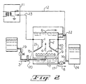
- Figure 1 is a schematic overview of an embodiment of the present process as it relates to the separation of an emulsion of water in a polydiorganosiloxane polymer.
- Figure 2 is a schematic representation of significant elements of an apparatus suitable for conduct of the present process.
- FIG. 1 An overview of an embodiment of the present process where the continuous phase is a silicone fluid, such as polydimethylsiloxane, and the discontinuous phase is water is presented in Figure 1.
- electrodes 1 and 2 are shown, arranged vertically and parallel to each other and to the flow of fluids within a treater shell.
- the emulsion is directed toward the electrodes along path 3 which is generally lower than the electrodes.
- the flow of the emulsion from path 3 is then directed upward along path 4.
- Any water droplets that coalesce to a size large enough to gravitate from the emulsion travel downward along path 5.
- the silicone fluid continues upward along path 6 for delivery as a dehydrated product of the process.
- the controlled removal of water is exerted to maintain water interface 9 at a predetermined distance below electrodes 1 and 2.
- the potential applied to the electrodes is shown as a DC voltage generated by rectifying AC voltage into half-wave negative and positive components thereby providing a pulsed positive DC voltage to one electrode and a pulsed DC negative voltage to the other electrode.
- the nature of the electrical potential supplied to the electrodes in Figure 1 is not meant to be limiting on the present process and this potential can be supplied as an AC potential, DC potential, pulsed DC potential, a combination of AC and DC potentials or as an electrical potential having both AC and DC characteristics.
- One preferred process of our invention uses one or more pairs of electrodes connected to an AC energized transformer, one end of the transformer secondary winding being connected to ground and the other connected to the electrodes through rectifier elements, such that the AC supply is split into its pulsed unidirectional components. On each half cycle of the AC voltage source, voltage is applied to one electrode of the pair while the other electrode of said pair has no voltage applied to it.
- a fluctuating unidirectional field is therefore produced between the electrodes by the alternate pulsing of one electrode positive and the other electrode negative.
- the pulsating DC voltage applied to the electrodes may establish a field of an AC nature between the ends of the electrodes and the water interface 9 which is maintained at ground potential.
- Electrodes 1 and 2 are shown arranged vertically and parallel to each other and to the flow of fluids within treater shell 10. Electrodes 1 and 2 are connected to power supply 11 by means of electrical leads 12 and 13. Power supply 11 is a rectified AC voltage providing a pulsating DC voltage to the electrodes. Also positioned within treater shell 10 is distributor 14. Distributor 14 is of conventual design and comprises, for example, a notched or perforated inverted conduit having an H-shaped configuration. The emulsion is conveniently fed to distributor 14 along path 3 consisting of feed conduit 15 having positioned therein a feed control valve 19 and a flow meter 20. Feed control valve 19 is used to control the rate of feed of emulsion to distributor 14. The emulsion is preferably fed into treater shell 10 at a level below distributor 14 and above water interface 9.
- Water interface 9 is kept at a relatively constant level below distributor 14 by removal of bulk water 7 from treater shell 10 through outlet 16.
- the exit of bulk water 7 from the treater shell is controlled by means of outlet valve 17 which may be connected to an automatic level control system such as a float valve arrangement.
- the emulsion exiting distributor 14 is channeled by channeling plates 21 along path 4 passing between electrodes 1 and 2.
- the purpose of channeling plates 21 is to ensure the emulsion passes along path 4 and not behind electrodes 1 and 2.
- Channeling plates 21 are made of an inert non-conductive material such as Teflon (R) (Dupont Corporation, Wilmington, Delware).
- Emulsions that are readily separated by the present process comprise at least two immiscible liquids where one of the liquids is non-conducting and is present as a continuous phase.
- non-conducting we mean the liquid comprising the continuous phase has a conductivity such that the dielectric resistance between energized electrodes is maintained high enough to sustain an electric field between the electrodes sufficient to effect coalescence of the discontinuous phase.
- the nature of the continuous phase is limiting only in that under process conditions the continuous phase will be non-conductive and have a dielectric constant and density different than that of the discontinuous phase.
- the continuous phase is, for example, an organic solvent such as toluene, xylene, benzene and heptane.
- the continuous phase comprises a silicon containing compound or a silicon containing polymer.
- silicon containing compounds we mean those chemical entities comprising at least one silicon atom and being non-polymeric in structure.
- Each R 1 is selected, for example, from a group consisting of substituted and unsubstituted alkyls, cycloalkyls, alkenyls, araalkyls and aryls.
- R 1 is, for example, methyl, ethyl, chloromethyl, 3,3,3-trifluoropropyl, cyclopentyl, cyclohexyl, vinyl, allyl, 5-hexenyl, benzyl, beta-phenylethyl, phenyl, tolyl, xylyl, naphthyl and chlorophenyl.
- R 1 is methyl.
- each X is an independently selected halogen atom.
- Preferred in Formula 1 is where X is chlorine.
- the continuous phase of an emulsion separable by the present process can also be a silicon containing polymer.
- silicon containing polymer we mean those polymers in which the silicon atom is a substituent of the repeating units forming the polymer backbone chain.
- Examples of such silicon containing polymers include linear, branched and cyclic siloxanes; silicone resin precursors; polysilanes; and mixtures of two or more of these polymers.
- the silicon containing polymer is, for example, a linear siloxane described by formula R 2 R 3 2 SiO(SiR 3 2 O) z SiR 3 2 R 2 where each R 2 is independently selected from the group consisting of halogen, hydroxy and R 3 ; each R 3 is independently selected from hydrogen or monovalent hydrocarbon radicals comprising 1 to 12 carbon atoms and z is a value within a range of 0 to 100,000.
- each R 2 is independently selected from the group consisting of chlorine, hydroxy and methyl.
- R 3 is in addition to hydrogen, a substituted or unsubstituted alkyl, cycloalkyl, alkenyl and aryl as described for R 1 .
- R 3 substituents on silicon in formula (2) are methyl. It is also preferred in formula (2) that z be a value within a range of 0 to 700. More preferred is when z is within a range of 0 to 200.
- the silicon containing polymer is, for example, a cyclic siloxane described by formula where R 3 is as previously described and m is a value within a range of 3 to 20. Preferred is where m is within a range of 3 to 7.
- the silicon containing polymer is typically a branched polymer, suitable as a precursor for forming a silicone resin of units described by formulas R 3 3 SiO 1/2 , R 3 2 SiO 2/2 , R 3 SiO 3/2 and SiO 4/2 , where R 3 is as previously described.
- the silicon containing polymer can also be, for example, a polysilane described by formula R 4 3 Si(SiR 4 2 ) n SiR 4 3 where each R 4 is independently selected from the group consisting of hydrogen, halogen, R 1 as previously described and n is a value within a range of 0 to 1,000.
- the present process is particularly useful for reducing residual water and chloride present in polysiloxanes prepared by the hydrolysis of organochlorosilanes.
- Such a process is described, for example, in U.S. Patent 5,075,479, which teaches emulsions comprising silicon containing polymers as a continuous phase and an aqueous acid as a discontinuous phase that are separated by the present process.
- the discontinuous phase of the present process is any liquid immiscible with the continuous phase and having a dielectric constant and density different than that of said continuous phase.
- the discontinuous phase can be an organic solvent, silicon containing compound or silicon containing polymer such as described for the continuous phase; water; or aqueous acid.
- our claimed process is used to remove residual amount of silicon containing compounds and silicon containing polymers from solvents to facilitate recovery, recycle or disposal of solvents.
- the discontinuous phase of the emulsion is an aqueous acid, such as results from the hydrolysis of organohalosilanes to form organopolysiloxanes.
- the discontinuous phase is, for example, aqueous hydrogen chloride.
- the discontinuous phase of the emulsion must have a different dielectric constant than that of the continuous phase.
- the required difference in dielectric constant is dependent upon the particular configuration of electric field coalescer used to effect the present process and can be easily determined without undue experimentation by those skilled in the art.
- the dielectric constant of the discontinuous phase must be sufficiently different from that of the continuous phase to allow for migration of the droplets forming the discontinuous phase within the electric field created between charged electrodes.
- the discontinuous phase can also be electrically conductive. Examples of materials having differing dielectric constants that can be separated by the present process are provided herein.
- the material comprising the discontinuous phase must also have a different density than that of the material comprising the continuous phase.
- the present process effects coalescence of the discontinuous phase into droplets of a size for effective gravitation from the continuous phase. Therefore, the density of the material comprising the discontinuous phase must be such that coalesced droplets of the discontinuous phase are separated from the continuous phase based upon their buoyancy or settling in the continuous phase.
- the coalesced droplets of the discontinuous phase have a density that allows them to either migrate up or down within the continuous phase to effect a phase separation.
- the discontinuous phase has a density greater than that of the continuous phase causing the coalesced droplets of the discontinuous phase to settle toward the bottom of an electric field coalescer apparatus.
- the continuous phase is a silicon containing polymer
- water may be desirable herein to add water to our process to facilitate reduction of residual chlorine content of the silicon polymer.
- the added water comprising at least a portion of the discontinuous phase of the emulsion, will facilitate hydrolysis of chlorine atoms bonded to silicon atoms, thereby facilitating removal of chlorine from said silicon containing polymer.
- Aqueous hydrogen chloride solution having the acid concentration described in Table 1 (Inlet HCl) was emulsified in a PDMS fluid having a viscosity of 0.1 Pa ⁇ s at 25°C.
- the volume percent water (Inlet %H 2 O) and parts per million chloride (PPM Cl) in the emulsion is described in Table 1 for each run.
- the particle size of the aqueous acid phase in the emulsion was determined to be 20 micrometers or less with a median particle size of 10 as measured by use of a particle size analyzer (Lasentec Sensor Technology, Inc., Bellevue, WA).
- the emulsion was fed to an electric coalescer as generally described in Figure 2.
- the volume capacity of the coalescer was 64.4 1. (17 gallons).
- the coalescer was supplied with a rectified voltage of 18 kV and the emulsion was fed to the coalescer at a rate of 1200 ml/m. It was determined that the coalescer reached a steady state condition after 2.5 vessel displacements and a sample of the PDMS exiting the coalescer was collected and analyzed at this point for volume percent water (Outlet %H 2 O) and parts per million (PPM) chloride (Outlet PPM Cl). The volume percent water in the outlet stream was determined by standard methods using centrifugation to effect separation.
- the volume percent water emulsified in the PDMS fed to the reactor (Inlet %H 2 O) and the volume percent water in the PDMS exiting the reactor (Outlet %H 2 O) are also in Table 2.
- the weight percent water was determined by standard methods using centrifugation to effect separation. Effect of Emulsion Feed Velocity on Dehydration Feed Rate (ml/s) Velocity (X10 3 m/s) Inlet %H 2 O Outlet %H 2 O 20 1.29 8 0.03 40 2.59 5.5 0.07 56 3.63 5.5 0.10 80 5.78 6 0.12 160 10.31 5 0.40
- the effect of the voltage applied to the electric field coalescer on the ability to separate water in a PDMS emulsion was evaluated.
- An emulsion of water in PDMS fluid having a viscosity of 0.1 Pa ⁇ s at 25°C. was created.
- the volume percent of water emulsified in said fluid is reported in Table 3 (Inlet %H2O).
- the water droplet size in the emulsion was similar to that described in Example 1.
- the emulsion was fed to the electrostatic coalescer of Example 1 at 1200 ml/m at various applied voltages as listed in Table 3.
- the coalescer was run at ambient temperature. Incremental increases in the applied voltage to the coalescer were made as described in Table 3.
- Example 3 The volume percent water emulsified in the PDMS fluid fed to the reactor (Inlet %H 2 O) and the volume percent water in the PDMS fluid exiting the reactor (Outlet %H 2 O) are reported in Table 3. The volume percent water was determined in the outlet liquid by standard methods using centrifugation to effect separation.
Description
- The present invention is a process for separating an emulsion by electric field enhanced coalescence, where the emulsion comprises a discontinuous phase and a non-conducting continuous phase and the two phases have different dielectric constants and densities and at least one of the phases comprises a silicon containing compound or a silicon containing polymer. Herein, the emulsion is exposed to an electric field thereby effecting coalescence of the discontinuous phase into droplets of a size for effective gravitation from the continuous phase.
- The use of high voltage electric fields to force the separation of oil field emulsions is a well known and accepted practice in the petroleum industry. These fields greatly speed the coalescence and separation of immiscible liquids, over conventional heat treaters and settlers using mechanical aids to accomplish coalescence.
- This art is generally represented by U.S. Patents 3,207,686 and 3,342,720.
- Moreover, in processes for dehydrating crude petroleum-aqueous emulsions by effecting coalescence in an electric field, the nature of the current provided to the electrodes is important in determining process efficiency. It is believed that an electric field created by an AC voltage source is more effective in separating relatively wet emulsions while an electric field created by a DC voltage source is more effective in separating dryer emulsions where particle size of the aqueous phase is small. Therefore apparatuses employing electrical fields of both AC and DC characteristics have been described.
- This latter art is represented by U.S. Patents 3,772,180; 3,939,395; 4,054,451; 4,308,127 and 4,126,537.
- The above described patents specifically address the problems associated with dehydrating crude oil and petroleum distillates in the petroleum industry. Said patents do not recognize that silicon containing compounds and silicon containing polymers represent unique materials that can exist in emulsion with other liquids and that such emulsions with two phases having different dielectric constants and densities may be separated by exposure.to an electric field to enhance coalescence of the discontinuous phase into droplets of a size for effective gravitation from the continuous phase.
- WO 88/02274 relates to a method of treating a fluid solution by applying a non-uniform field, which may be electric or magnetic, to the solution while maintaining the solution under near critical conditions of temperature and pressure which deflects one of the components of the solution to a greater extent than the others. The method is applicable to true solutions i.e. homogeneous mixtures of two or more substances.
- The invention is a process for separating an emulsion into separate and easily recoverable phases. The process comprises exposing an emulsion comprising a discontinuous phase and a non-conducting continuous phase to an electric field thereby effecting coalescence of the discontinuous phase into droplets of a size for effective gravitation from the continuous phase, where the discontinuous phase and the continuous phase have different dielectric constants and densities and at least one of the phases comprises a silicon containing compound or a silicon containing polymer. Our process is especially useful for separating emulsions where the discontinuous phase is an aqueous acid solution and the continuous phase is diorganopolysiloxane.
- Figure 1 is a schematic overview of an embodiment of the present process as it relates to the separation of an emulsion of water in a polydiorganosiloxane polymer.
- Figure 2 is a schematic representation of significant elements of an apparatus suitable for conduct of the present process.
- Our method of exposing the emulsion to an electric field and the apparatus for effecting such exposure is not critical to the present invention and can be any of those known in the art. By way of example, an overview of an embodiment of the present process where the continuous phase is a silicone fluid, such as polydimethylsiloxane, and the discontinuous phase is water is presented in Figure 1. In Figure 1, electrodes 1 and 2 are shown, arranged vertically and parallel to each other and to the flow of fluids within a treater shell. The emulsion is directed toward the electrodes along path 3 which is generally lower than the electrodes. The flow of the emulsion from path 3 is then directed upward along path 4. Any water droplets that coalesce to a size large enough to gravitate from the emulsion travel downward along path 5. After treatment by exposure to electric fields, the silicone fluid continues upward along path 6 for delivery as a dehydrated product of the process.
- The water which is separated from the emulsion flowing along path 5, collects as bulk water 7. A controlled removal of water from bulk water 7 is effected along path 8. The controlled removal of water is exerted to maintain
water interface 9 at a predetermined distance below electrodes 1 and 2. In Figure 1, the potential applied to the electrodes is shown as a DC voltage generated by rectifying AC voltage into half-wave negative and positive components thereby providing a pulsed positive DC voltage to one electrode and a pulsed DC negative voltage to the other electrode. - The nature of the electrical potential supplied to the electrodes in Figure 1 is not meant to be limiting on the present process and this potential can be supplied as an AC potential, DC potential, pulsed DC potential, a combination of AC and DC potentials or as an electrical potential having both AC and DC characteristics. One preferred process of our invention uses one or more pairs of electrodes connected to an AC energized transformer, one end of the transformer secondary winding being connected to ground and the other connected to the electrodes through rectifier elements, such that the AC supply is split into its pulsed unidirectional components. On each half cycle of the AC voltage source, voltage is applied to one electrode of the pair while the other electrode of said pair has no voltage applied to it. A fluctuating unidirectional field is therefore produced between the electrodes by the alternate pulsing of one electrode positive and the other electrode negative. Under conditions of Figure 1, the pulsating DC voltage applied to the electrodes may establish a field of an AC nature between the ends of the electrodes and the
water interface 9 which is maintained at ground potential. - The method of exposure of the emulsion to the electric field and an apparatus suitable for such exposure is further detailed by Figure 2. In Figure 2, electrodes 1 and 2 are shown arranged vertically and parallel to each other and to the flow of fluids within treater shell 10. Electrodes 1 and 2 are connected to power supply 11 by means of
electrical leads feed control valve 19 and aflow meter 20.Feed control valve 19 is used to control the rate of feed of emulsion to distributor 14. The emulsion is preferably fed into treater shell 10 at a level below distributor 14 and abovewater interface 9. -
Water interface 9 is kept at a relatively constant level below distributor 14 by removal of bulk water 7 from treater shell 10 throughoutlet 16. The exit of bulk water 7 from the treater shell is controlled by means ofoutlet valve 17 which may be connected to an automatic level control system such as a float valve arrangement. The emulsion exiting distributor 14 is channeled bychanneling plates 21 along path 4 passing between electrodes 1 and 2. The purpose of channelingplates 21 is to ensure the emulsion passes along path 4 and not behind electrodes 1 and 2.Channeling plates 21 are made of an inert non-conductive material such as Teflon (R) (Dupont Corporation, Wilmington, Delware). As the emulsion passes between electrodes 1 and 2, coalescence of the aqueous phase is effected causing the formation of drops large enough to settle by gravitation from the emulsion. The aqueous drops settle into bulk water 7. The dehydrated silicone fluid continues upward along path 6 through treater shell 10 exiting atfluid outlet 22 and passes through conduit 23 tostorage container 24. - It will be readily appreciated by those skilled in the art that the embodiments of the present invention as described by reference to Figure 1 and Figure 2 are not exclusive and that other embodiments could be readily fashioned from the disclosure herein without the exercise of inventive skill. More, specifically the number, configuration, design and location of the electrodes; the type of voltage supplied to said electrodes, including the method of control; the distributor, number, design and location; the methods for feeding dispersion to the electric field coalescer unit; and methods for removing separated components from the coalescer can be any of those typically associated with such processes. Specific examples of electric field coalescer units which are useful in our process include those described in U.S. Patents 3,342,720; 3,207,686; 3,772,180; 4,056,451 and 4,126,537.
- Emulsions that are readily separated by the present process comprise at least two immiscible liquids where one of the liquids is non-conducting and is present as a continuous phase. By "non-conducting", we mean the liquid comprising the continuous phase has a conductivity such that the dielectric resistance between energized electrodes is maintained high enough to sustain an electric field between the electrodes sufficient to effect coalescence of the discontinuous phase.
- The nature of the continuous phase is limiting only in that under process conditions the continuous phase will be non-conductive and have a dielectric constant and density different than that of the discontinuous phase. The continuous phase is, for example, an organic solvent such as toluene, xylene, benzene and heptane.
- Preferred is when the continuous phase comprises a silicon containing compound or a silicon containing polymer. By silicon containing compounds, we mean those chemical entities comprising at least one silicon atom and being non-polymeric in structure. Examples of silicon containing compounds which comprise the continuous phase of an emulsion separable by the present process include silanes described by formula
- The continuous phase of an emulsion separable by the present process can also be a silicon containing polymer. By silicon containing polymer, we mean those polymers in which the silicon atom is a substituent of the repeating units forming the polymer backbone chain. Examples of such silicon containing polymers include linear, branched and cyclic siloxanes; silicone resin precursors; polysilanes; and mixtures of two or more of these polymers.
- The silicon containing polymer is, for example, a linear siloxane described by formula
- The silicon containing polymer is, for example, a cyclic siloxane described by formulawhere R3 is as previously described and m is a value within a range of 3 to 20. Preferred is where m is within a range of 3 to 7.

- The silicon containing polymer is typically a branched polymer, suitable as a precursor for forming a silicone resin of units described by formulas R3 3SiO1/2, R3 2SiO2/2, R3SiO3/2 and SiO4/2, where R3 is as previously described.
- The silicon containing polymer can also be, for example, a polysilane described by formula
- The present process is particularly useful for reducing residual water and chloride present in polysiloxanes prepared by the hydrolysis of organochlorosilanes. Such a process is described, for example, in U.S. Patent 5,075,479, which teaches emulsions comprising silicon containing polymers as a continuous phase and an aqueous acid as a discontinuous phase that are separated by the present process.
- The discontinuous phase of the present process is any liquid immiscible with the continuous phase and having a dielectric constant and density different than that of said continuous phase. The discontinuous phase can be an organic solvent, silicon containing compound or silicon containing polymer such as described for the continuous phase; water; or aqueous acid. Within the limitations described for the continuous phase and the discontinuous phase, our claimed process is used to remove residual amount of silicon containing compounds and silicon containing polymers from solvents to facilitate recovery, recycle or disposal of solvents. In a preferred process, the discontinuous phase of the emulsion is an aqueous acid, such as results from the hydrolysis of organohalosilanes to form organopolysiloxanes. The discontinuous phase is, for example, aqueous hydrogen chloride.
- The discontinuous phase of the emulsion must have a different dielectric constant than that of the continuous phase. The required difference in dielectric constant is dependent upon the particular configuration of electric field coalescer used to effect the present process and can be easily determined without undue experimentation by those skilled in the art. Generally, the dielectric constant of the discontinuous phase must be sufficiently different from that of the continuous phase to allow for migration of the droplets forming the discontinuous phase within the electric field created between charged electrodes. The discontinuous phase can also be electrically conductive. Examples of materials having differing dielectric constants that can be separated by the present process are provided herein.
- The material comprising the discontinuous phase must also have a different density than that of the material comprising the continuous phase. The present process effects coalescence of the discontinuous phase into droplets of a size for effective gravitation from the continuous phase. Therefore, the density of the material comprising the discontinuous phase must be such that coalesced droplets of the discontinuous phase are separated from the continuous phase based upon their buoyancy or settling in the continuous phase. In the present process, the coalesced droplets of the discontinuous phase have a density that allows them to either migrate up or down within the continuous phase to effect a phase separation. In a preferred process the discontinuous phase has a density greater than that of the continuous phase causing the coalesced droplets of the discontinuous phase to settle toward the bottom of an electric field coalescer apparatus.
- When the continuous phase is a silicon containing polymer, it may be desirable herein to add water to our process to facilitate reduction of residual chlorine content of the silicon polymer. The added water, comprising at least a portion of the discontinuous phase of the emulsion, will facilitate hydrolysis of chlorine atoms bonded to silicon atoms, thereby facilitating removal of chlorine from said silicon containing polymer.
- The following examples are provided to further illustrate the present invention.
- The ability to dehydrate and reduce the chlorine content of a polydimethylsiloxane (PDMS) fluid by electric field enhanced coalescence was evaluated. Aqueous hydrogen chloride solution having the acid concentration described in Table 1 (Inlet HCl) was emulsified in a PDMS fluid having a viscosity of 0.1 Pa·s at 25°C. The volume percent water (Inlet %H2O) and parts per million chloride (PPM Cl) in the emulsion is described in Table 1 for each run. The particle size of the aqueous acid phase in the emulsion was determined to be 20 micrometers or less with a median particle size of 10 as measured by use of a particle size analyzer (Lasentec Sensor Technology, Inc., Bellevue, WA). The emulsion was fed to an electric coalescer as generally described in Figure 2. The volume capacity of the coalescer was 64.4 1. (17 gallons). The coalescer was supplied with a rectified voltage of 18 kV and the emulsion was fed to the coalescer at a rate of 1200 ml/m. It was determined that the coalescer reached a steady state condition after 2.5 vessel displacements and a sample of the PDMS exiting the coalescer was collected and analyzed at this point for volume percent water (Outlet %H2O) and parts per million (PPM) chloride (Outlet PPM Cl). The volume percent water in the outlet stream was determined by standard methods using centrifugation to effect separation. The PPM Cl in the outlet stream was determined by ion chromatography (IC). The results of these analyses are reported in Table 1.
PDMS Dehydration and Chloride Removal Inlet Outlet Run Temp. (°C) Inlet HCL Conc. (Wt.%) %H2O PPM Cl %H2O PPM Cl 1 38 1 - 1.1 2.4 250 trace 2.8 2 31 2 - 2.1 2.3 473 trace 0.6 3 24 8.4 - 8.5 9 7594 0.02 2.7 - The effect of feed velocity on separation of an emulsion of water in PDMS and electric field coalescer was evaluated. An emulsion of water in PDMS fluid having a viscosity of 0.1 Pa·s at 25°C. was created. The water droplet size in said emulsion was similar to that described in Example 1. The emulsion was fed to the electric field coalescer of Example 1 at various feed rates (Feed Rate) as described in Table 2 providing a velocity (Velocity) within the coalescer as also reported in Table 2. The coalescer was run at ambient temperature. The volume percent water emulsified in the PDMS fed to the reactor (Inlet %H2O) and the volume percent water in the PDMS exiting the reactor (Outlet %H2O) are also in Table 2. The weight percent water was determined by standard methods using centrifugation to effect separation.
Effect of Emulsion Feed Velocity on Dehydration Feed Rate (ml/s) Velocity (X103 m/s) Inlet %H2O Outlet %H2O 20 1.29 8 0.03 40 2.59 5.5 0.07 56 3.63 5.5 0.10 80 5.78 6 0.12 160 10.31 5 0.40 - The effect of the voltage applied to the electric field coalescer on the ability to separate water in a PDMS emulsion was evaluated. An emulsion of water in PDMS fluid having a viscosity of 0.1 Pa·s at 25°C. was created. The volume percent of water emulsified in said fluid is reported in Table 3 (Inlet %H2O). The water droplet size in the emulsion was similar to that described in Example 1. The emulsion was fed to the electrostatic coalescer of Example 1 at 1200 ml/m at various applied voltages as listed in Table 3. The coalescer was run at ambient temperature. Incremental increases in the applied voltage to the coalescer were made as described in Table 3. At each voltage, the coalescer was allowed to reach steady state as described in Example 1 before a sample was taken from the exit stream for analysis. The volume percent water emulsified in the PDMS fluid fed to the reactor (Inlet %H2O) and the volume percent water in the PDMS fluid exiting the reactor (Outlet %H2O) are reported in Table 3. The volume percent water was determined in the outlet liquid by standard methods using centrifugation to effect separation.
Effects of Applied Voltage on Dehydration of PDMS Applied Voltage (kV) Inlet %H2O Outlet %H2O 18 2.2 0.050 20 2.3 0.035 22 2.5 0.035 24 2.7 0.035 26 2.5 0.035 28 2.6 0.035 30 2.6 0.035 32 2.5 0.030 34 2.6 0.020 36 2.6 0.020 38 2.7 0.020 40 2.7 0.025 42 2.8 0.025 44 2.9 0.025 46 3.0 0.025 48 3.0 0.050
Claims (13)
- A process for separating an emulsion, the process comprising exposing an emulsion comprising a discontinuous phase and a non-conducting continuous phase to an electric field effecting coalescence of the discontinuous phase into droplets of a size for effective gravitation from the continuous phase, where the continuous phase and the discontinuous phase have different dielectric constants and densities and at least one of the phases comprises a silicon containing compound or silicon containing polymer.
- A process for dehydrating a silicone polymer, the process comprising passing an emulsion comprising a discontinuous aqueous phase and a continuous phase comprising a polydiorganosiloxane through an electric field having an alternating current field component and a direct current field component, thereby effecting coalescence of the aqueous phase into droplets of a size sufficient for gravitation from the polydiorganosiloxane.
- A process according to claims 1 or 2 where the electric field is created by an alternating current potential or a direct current potential applied to one or more electrodes.
- A process according to claims 1 or 2 where the electric field is created by a pulsed direct current potential applied to one or more electrodes.
- A process according to claims 1 or 2 where the electric field is created by an electric potential having both alternating current and direct current characteristics applied to one or more electrodes.
- A process according to claim 1 where the continuous phase comprises a silicon containing compound or a silicon containing polymer.
- A process according to claim 1 where the continuous phase is a silane described by formula
- A process according to claim 1 where the continuous phase is a linear siloxane described by formula
- A process according to claim 1 where the continuous phase is a cyclic siloxane described by formulawhere each R3 is independently selected from hydrogen atom or monovalent hydrocarbon radicals comprising 1 to 12 carbon atoms and m is a value within a range of 3 to 20.

- A process according to claim 1 where the continuous phase is a silicone resin formed of units described by formulas R3 3SiO1/2, R3 2SiO2/2, R3SiO3/2 and SiO4/2, where each R3 is independently selected from hydrogen atom or monovalent hydrocarbon radicals comprising 1 to 12 carbon atoms.
- A process according to claim 1 where the continuous phase is a polysilane described by formula
- A process according to claim 1 where the discontinuous phase is selected from water, aqueous acid and aqueous hydrogen chloride.
- A process according to claim 2 where the continuous phase is a polydimethylsiloxane prepared by the hydrolysis of methylchlorosilanes, the discontinuous phase is aqueous hydrogen chloride and water is added to the process to facilitate reduction of residual chlorine bonded to silicon atoms of the polydimethylsiloxane.
Applications Claiming Priority (2)
| Application Number | Priority Date | Filing Date | Title |
|---|---|---|---|
| US747531 | 1996-11-12 | ||
| US08/747,531 US5861089A (en) | 1996-11-12 | 1996-11-12 | Electric field enhanced coalescence of emulsions comprising a silicon containing compound or silicon containing polymer |
Publications (3)
| Publication Number | Publication Date |
|---|---|
| EP0841362A2 EP0841362A2 (en) | 1998-05-13 |
| EP0841362A3 EP0841362A3 (en) | 1999-01-07 |
| EP0841362B1 true EP0841362B1 (en) | 2003-06-18 |
Family
ID=25005476
Family Applications (1)
| Application Number | Title | Priority Date | Filing Date |
|---|---|---|---|
| EP97308866A Expired - Lifetime EP0841362B1 (en) | 1996-11-12 | 1997-11-05 | Electric field enhanced coalescence of silicone emulsions |
Country Status (4)
| Country | Link |
|---|---|
| US (1) | US5861089A (en) |
| EP (1) | EP0841362B1 (en) |
| JP (1) | JPH10151368A (en) |
| DE (1) | DE69722895T2 (en) |
Cited By (2)
| Publication number | Priority date | Publication date | Assignee | Title |
|---|---|---|---|---|
| US7300593B2 (en) | 2003-06-27 | 2007-11-27 | The Procter & Gamble Company | Process for purifying a lipophilic fluid |
| US7300594B2 (en) | 2003-06-27 | 2007-11-27 | The Procter & Gamble Company | Process for purifying a lipophilic fluid by modifying the contaminants |
Families Citing this family (17)
| Publication number | Priority date | Publication date | Assignee | Title |
|---|---|---|---|---|
| US6126803A (en) * | 1998-10-19 | 2000-10-03 | Dow Corning Corporation | Method for removing particulate from a liquid silicon containing compound |
| AU6820001A (en) * | 2000-06-05 | 2001-12-17 | Procter & Gamble | Process for treating a lipophilic fluid |
| US6706076B2 (en) | 2000-06-05 | 2004-03-16 | Procter & Gamble Company | Process for separating lipophilic fluid containing emulsions with electric coalescence |
| US6930079B2 (en) | 2000-06-05 | 2005-08-16 | Procter & Gamble Company | Process for treating a lipophilic fluid |
| AU7525901A (en) * | 2000-06-05 | 2001-12-17 | Procter & Gamble | A process for separating lipophilic fluid containing emulsions with electric coalescence |
| US6914040B2 (en) | 2001-05-04 | 2005-07-05 | Procter & Gamble Company | Process for treating a lipophilic fluid in the form of a siloxane emulsion |
| CA2457353C (en) | 2001-09-10 | 2008-08-26 | The Procter & Gamble Company | Method for processing a lipophilic fluid |
| US7276162B2 (en) | 2001-09-10 | 2007-10-02 | The Procter & Gamble Co. | Removal of contaminants from a lipophilic fluid |
| AR036777A1 (en) | 2001-09-10 | 2004-10-06 | Procter & Gamble | FILTER TO REMOVE WATER AND / OR SURFACTANTS FROM A LIPOFILO FLUID |
| US6955761B2 (en) | 2001-09-10 | 2005-10-18 | Procter & Gamble Company | Multifunctional filter |
| US6726743B2 (en) * | 2002-06-18 | 2004-04-27 | 3M Innovative Properties Company | Electrostatic deaeration method and apparatus |
| US7297277B2 (en) | 2003-06-27 | 2007-11-20 | The Procter & Gamble Company | Method for purifying a dry cleaning solvent |
| CN104515692B (en) * | 2014-12-12 | 2017-05-31 | 中国石油大学(华东) | A kind of electrostatic coalescence RES(rapid evaluation system) and method |
| EP3199217B1 (en) | 2016-01-29 | 2020-08-05 | Borealis AG | Methods for the treatment of at least one emulsion by applying an electrical field |
| US10513663B2 (en) | 2018-01-09 | 2019-12-24 | Saudi Arabian Oil Company | Gas oil separation plant systems and methods for rag layer treatment |
| US11034893B2 (en) | 2018-01-09 | 2021-06-15 | Saudi Arabian Oil Company | Desalting plant systems and methods for enhanced tight emulsion crude oil treatment |
| CN113277598B (en) * | 2021-06-28 | 2022-07-12 | 重庆工商大学 | Method and device for treating oily wastewater by coalescence of electric field and corrugated plate |
Family Cites Families (14)
| Publication number | Priority date | Publication date | Assignee | Title |
|---|---|---|---|---|
| US3207686A (en) * | 1962-03-07 | 1965-09-21 | Nat Tank Co | Electric dehydrator |
| US3342720A (en) * | 1964-07-28 | 1967-09-19 | Petrolite Corp | Electric treater |
| US3772180A (en) * | 1971-11-10 | 1973-11-13 | Combustion Eng | Electric treater |
| US3847775A (en) * | 1971-11-10 | 1974-11-12 | Combustion Eng | Process for electrical coalescing of water |
| US3939395A (en) * | 1972-04-17 | 1976-02-17 | Combustion Engineering, Inc. | System for connecting and disconnecting power source terminals to a load for time proportional to the current drawn by the load |
| US4056451A (en) * | 1976-03-29 | 1977-11-01 | Maloney-Crawford Tank Corporation | Dual field electric treater |
| US4126537A (en) * | 1977-07-15 | 1978-11-21 | Combustion Engineering, Inc. | Method and apparatus for separation of fluids with an electric field |
| US4308127A (en) * | 1980-03-17 | 1981-12-29 | Combustion Engineering, Inc. | Separation of emulsions with electric field |
| US4545914A (en) * | 1984-08-31 | 1985-10-08 | Dow Corning Corporation | Conductive elastomers from electrically conductive fibers in silicone emulsion |
| US4786387A (en) * | 1986-09-25 | 1988-11-22 | Whitlock David R | Single phase enrichment of super critical fluids |
| US5036365A (en) * | 1988-11-21 | 1991-07-30 | Benzion Landa | Field assisted filter and electrophotographic copying machine using the same |
| US5075479A (en) * | 1991-05-20 | 1991-12-24 | Dow Corning Corporation | Anhydrous hydrogen chloride evolving one-step process for producing siloxanes |
| JPH06100694A (en) * | 1992-09-22 | 1994-04-12 | Nippon Dow Corning Kk | Production of branched polyorganosiloxane |
| RU2094128C1 (en) * | 1996-01-30 | 1997-10-27 | Научно-исследовательский институт электронных материалов | Apparatus for continuous electrostatic cleaning of low-molecular polydimethylsiloxane rubber and method of cleaning |
-
1996
- 1996-11-12 US US08/747,531 patent/US5861089A/en not_active Expired - Lifetime
-
1997
- 1997-11-05 EP EP97308866A patent/EP0841362B1/en not_active Expired - Lifetime
- 1997-11-05 DE DE69722895T patent/DE69722895T2/en not_active Expired - Fee Related
- 1997-11-12 JP JP9310761A patent/JPH10151368A/en active Pending
Cited By (2)
| Publication number | Priority date | Publication date | Assignee | Title |
|---|---|---|---|---|
| US7300593B2 (en) | 2003-06-27 | 2007-11-27 | The Procter & Gamble Company | Process for purifying a lipophilic fluid |
| US7300594B2 (en) | 2003-06-27 | 2007-11-27 | The Procter & Gamble Company | Process for purifying a lipophilic fluid by modifying the contaminants |
Also Published As
| Publication number | Publication date |
|---|---|
| US5861089A (en) | 1999-01-19 |
| DE69722895T2 (en) | 2004-05-19 |
| EP0841362A3 (en) | 1999-01-07 |
| EP0841362A2 (en) | 1998-05-13 |
| DE69722895D1 (en) | 2003-07-24 |
| JPH10151368A (en) | 1998-06-09 |
Similar Documents
| Publication | Publication Date | Title |
|---|---|---|
| EP0841362B1 (en) | Electric field enhanced coalescence of silicone emulsions | |
| Eow et al. | Electrostatic enhancement of coalescence of water droplets in oil: a review of the technology | |
| CA1201412A (en) | Electrically enhanced inclined plate separator | |
| US5106468A (en) | Electrophoretic separation | |
| US5219471A (en) | Removal of metals and water-insoluble materials from desalter emulsions | |
| WO2010008911A2 (en) | Dynamic desalter simulator | |
| US2849395A (en) | Method and apparatus for electrical separation of emulsions | |
| US4581112A (en) | Method and apparatus for separating wax/water from hydrocarbon mixture boiling in the lubricating oil range | |
| EP2723817B1 (en) | Biodegradable polyorganosiloxane demulsifier composition and method for making the same | |
| CA1125231A (en) | Process for dehydration and demineralization of diluted bitumen | |
| US10112850B2 (en) | System to reduce interface emulsion layer formation in an electrostatic dehydrator or desalter vessel through use of a low voltage electrostatic interface emulsion treatment system inside the vessel | |
| US987115A (en) | Separating and collecting particles of one liquid suspended in another liquid. | |
| US4248686A (en) | Cross flow electrofilter and method | |
| JPS6133249A (en) | Charging device and method of fluid containing disperse phase | |
| Drelich et al. | The effect of electric field pulsation frequency on breaking water-in-oil emulsions | |
| US6126803A (en) | Method for removing particulate from a liquid silicon containing compound | |
| CA1165713A (en) | Recovery of hydrocarbons from aqueous tailings | |
| EP0042674B1 (en) | Process for refining electric insulating liquids | |
| CN1230131A (en) | Electrostatic coalescence | |
| KR870001121Y1 (en) | Electrode system with multiple electric fields | |
| Warren et al. | The Electrodynamic Contactor for Extraction | |
| RU2094128C1 (en) | Apparatus for continuous electrostatic cleaning of low-molecular polydimethylsiloxane rubber and method of cleaning | |
| Tarantsev | Electrohydrodynamic flows of media along the interface between gas–liquid phases | |
| SU1065027A1 (en) | Method of purifying water | |
| EP0179135A1 (en) | Separating a component which forms a dispersion in, or which is dissolved in, continuous liquid. |
Legal Events
| Date | Code | Title | Description |
|---|---|---|---|
| PUAI | Public reference made under article 153(3) epc to a published international application that has entered the european phase |
Free format text: ORIGINAL CODE: 0009012 |
|
| AK | Designated contracting states |
Kind code of ref document: A2 Designated state(s): DE FR GB NL |
|
| AX | Request for extension of the european patent |
Free format text: AL;LT;LV;MK;RO;SI |
|
| PUAL | Search report despatched |
Free format text: ORIGINAL CODE: 0009013 |
|
| AK | Designated contracting states |
Kind code of ref document: A3 Designated state(s): AT BE CH DE DK ES FI FR GB GR IE IT LI LU MC NL PT SE |
|
| AX | Request for extension of the european patent |
Free format text: AL;LT;LV;MK;RO;SI |
|
| 17P | Request for examination filed |
Effective date: 19990127 |
|
| AKX | Designation fees paid |
Free format text: DE FR GB NL |
|
| 17Q | First examination report despatched |
Effective date: 20020402 |
|
| GRAH | Despatch of communication of intention to grant a patent |
Free format text: ORIGINAL CODE: EPIDOS IGRA |
|
| GRAH | Despatch of communication of intention to grant a patent |
Free format text: ORIGINAL CODE: EPIDOS IGRA |
|
| GRAA | (expected) grant |
Free format text: ORIGINAL CODE: 0009210 |
|
| AK | Designated contracting states |
Designated state(s): DE FR GB NL |
|
| PG25 | Lapsed in a contracting state [announced via postgrant information from national office to epo] |
Ref country code: NL Free format text: LAPSE BECAUSE OF FAILURE TO SUBMIT A TRANSLATION OF THE DESCRIPTION OR TO PAY THE FEE WITHIN THE PRESCRIBED TIME-LIMIT Effective date: 20030618 |
|
| REG | Reference to a national code |
Ref country code: GB Ref legal event code: FG4D |
|
| REF | Corresponds to: |
Ref document number: 69722895 Country of ref document: DE Date of ref document: 20030724 Kind code of ref document: P |
|
| PG25 | Lapsed in a contracting state [announced via postgrant information from national office to epo] |
Ref country code: GB Free format text: LAPSE BECAUSE OF NON-PAYMENT OF DUE FEES Effective date: 20031105 |
|
| NLV1 | Nl: lapsed or annulled due to failure to fulfill the requirements of art. 29p and 29m of the patents act | ||
| ET | Fr: translation filed | ||
| PLBE | No opposition filed within time limit |
Free format text: ORIGINAL CODE: 0009261 |
|
| STAA | Information on the status of an ep patent application or granted ep patent |
Free format text: STATUS: NO OPPOSITION FILED WITHIN TIME LIMIT |
|
| 26N | No opposition filed |
Effective date: 20040319 |
|
| GBPC | Gb: european patent ceased through non-payment of renewal fee |
Effective date: 20031105 |
|
| PGFP | Annual fee paid to national office [announced via postgrant information from national office to epo] |
Ref country code: DE Payment date: 20061102 Year of fee payment: 10 |
|
| PGFP | Annual fee paid to national office [announced via postgrant information from national office to epo] |
Ref country code: FR Payment date: 20061108 Year of fee payment: 10 |
|
| PG25 | Lapsed in a contracting state [announced via postgrant information from national office to epo] |
Ref country code: DE Free format text: LAPSE BECAUSE OF NON-PAYMENT OF DUE FEES Effective date: 20080603 |
|
| REG | Reference to a national code |
Ref country code: FR Ref legal event code: ST Effective date: 20080930 |
|
| PG25 | Lapsed in a contracting state [announced via postgrant information from national office to epo] |
Ref country code: FR Free format text: LAPSE BECAUSE OF NON-PAYMENT OF DUE FEES Effective date: 20071130 |