EP0841294A2 - Suspended load steadying control device - Google Patents
Suspended load steadying control device Download PDFInfo
- Publication number
- EP0841294A2 EP0841294A2 EP97308303A EP97308303A EP0841294A2 EP 0841294 A2 EP0841294 A2 EP 0841294A2 EP 97308303 A EP97308303 A EP 97308303A EP 97308303 A EP97308303 A EP 97308303A EP 0841294 A2 EP0841294 A2 EP 0841294A2
- Authority
- EP
- European Patent Office
- Prior art keywords
- trolley
- control
- speed
- suspended load
- optimum
- Prior art date
- Legal status (The legal status is an assumption and is not a legal conclusion. Google has not performed a legal analysis and makes no representation as to the accuracy of the status listed.)
- Granted
Links
Images


Classifications
-
- B—PERFORMING OPERATIONS; TRANSPORTING
- B66—HOISTING; LIFTING; HAULING
- B66C—CRANES; LOAD-ENGAGING ELEMENTS OR DEVICES FOR CRANES, CAPSTANS, WINCHES, OR TACKLES
- B66C13/00—Other constructional features or details
- B66C13/04—Auxiliary devices for controlling movements of suspended loads, or preventing cable slack
- B66C13/06—Auxiliary devices for controlling movements of suspended loads, or preventing cable slack for minimising or preventing longitudinal or transverse swinging of loads
- B66C13/063—Auxiliary devices for controlling movements of suspended loads, or preventing cable slack for minimising or preventing longitudinal or transverse swinging of loads electrical
-
- B—PERFORMING OPERATIONS; TRANSPORTING
- B66—HOISTING; LIFTING; HAULING
- B66C—CRANES; LOAD-ENGAGING ELEMENTS OR DEVICES FOR CRANES, CAPSTANS, WINCHES, OR TACKLES
- B66C13/00—Other constructional features or details
- B66C13/18—Control systems or devices
Definitions
- This invention relates to a suspended load steadying (i.e., swing stopping) control device for performing control for steadying of a suspended load in a crane.
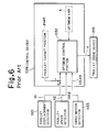
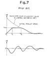
- FIG. 5 A conventional suspended load steadying control device will be described by reference to Fig. 5, a view showing an overall structure, Fig. 6, a block diagram of the control device, and Fig. 7 showing control characteristics.
- a trolley 012 can travel on rails 011 by the driving action of a trolley drive device 015. From the trolley 011, a rope 013 hangs down, and the trolley 011 transports a suspended load 014 by attaching the suspended load 014 to the front end of the rope 013.
- the trolley 012 is further provided with a trolley displacement detector 021 for detecting a trolley position, x1, a trolley speed detector 022 for detecting a trolley speed, x2, and a swing motion detector 023 for detecting a swing displacement, x3, and a swing speed, x4.
- a trolley displacement detector 021 for detecting a trolley position, x1
- a trolley speed detector 022 for detecting a trolley speed, x2
- a swing motion detector 023 for detecting a swing displacement, x3, and a swing speed, x4.
- the swing motion detector 023 is a detector of the type which photographs a marker attached to the suspended load 014 by means of a camera mounted on the trolley 012 vertically downwards, and image processes an image taken, thereby detecting the swing displacement x3 and swing speed x4.
- the trolley position x1, trolley speed x2, swing displacement x3 and swing speed x4 detected are sent to a control device 026.
- the control device 026 performs a positioning optimum control computation (to be described later on) by means of a built-in optimum control portion 032 (see Fig. 6), and produces a speed command, u. Under this speed command u, the trolley drive device 015 is driven to move the trolley 012.
- the crane can be modeled as a bogie-pendulum system, and it is known with such a model that the positioning of the suspended load can be realized by driving the trolley according to feedback control by an optimum regulator.
- a method for optimum control of the crane will be described.
- This control is performed by an optimum control portion (optimum regulator) 032 of a control device 026 which calculates the amount of operation (speed command, u, for the trolley in this embodiment) in accordance with the following control rule (Numeric Expression (1)):
- u Kx
- x represents a state amount vector to be described below, whose respective elements are, in order of arrangement from left to right, a trolley position x1, a trolley speed x2, a swing displacement x3 and a swing speed x4 of the suspended load. That is, the following Numeric Expression (2) holds.
- x [ x 1 x 2 x 3 x 4] T
- K [ k 1 k 2 k 3 k 4]
- the above gain vector K is an optimum gain determined by the following procedure:
- the optimum gain K is found which rapidly reduces all elements of the state amount to zero with the smallest possible operation amount (speed command) u.
- the control arithmetic unit 026 determines the amount of optimum operation by the sum of the products of the motion state amounts by the detectors 021, 022, 023 and the optimum gain K.
- the control arithmetic unit 026 issues this amount of optimum operation as a control command signal (speed command u) for the trolley drive device 015. By driving this device according to the signal, optimum control is performed.
- position signal input (trolley position x1) on the trolley 012 is given as feedback as a position relative to a trolley target position, pset, whereby the trolley 012 can be positioned at the target position. Simultaneously, the suspended load 014 can be steadied. Thus, the suspended load 014 can be brought to the given target position.
- the trolley When such control is performed by the optimum regulator, the trolley is moved from a stop state with the target position being changed. On this occasion, at the initial stage of control, the trolley position is far away from the target position. Hence, the relative position x1 of the trolley as a state amount takes a large value compared with other state amounts.
- the speed command u as the amount of operation also takes a large value immediately after initiation of control.
- the speed command u immediately after start of control is depicted as a dotted line (from time 0 to T2) in Fig. 7.
- the trolley in the initial state is at zero speed.
- the acceleration and speed of the trolley are also restricted. This necessitates acceleration at a maximum acceleration (from time 0 to T1) and movement at maximum speed (from time T1 to T2) at the initial stage of control.
- the trolley speed x2 in this case is indicated by a solid line in Fig. 7.
- That state of the trolley speed is effective for making the trolley reach the target position promptly, but it is a state in which no feedback on the swing state of the suspended load works. As a result, the trolley approaches the target position while retaining swings occurring as the trolley is accelerated.
- a suspended load steadying control device which performs, in addition to conventional optimum control, optimum control for carrying out steadying control while causing a trolley to follow a given speed command, and which has a switching device for switching between these two manners of control in accordance with the state of run.
- the trolley motion state amount detector may comprise a trolley displacement detector for detecting a trolley position, and a trolley speed detector for detecting a trolley speed.
- the suspended load motion state amount detector may be a swing motion detector for detecting the swing displacement and swing speed of the suspended load.
- the run state-wise control selection portion may be constructed as follows: When the relative position of the trolley to the target position is larger than a set value, the run state-wise control selection portion selects the speed following optimum control portion to drive the trolley. When the relative position of the trolley to the target position is smaller than the set value, on the other hand, the run state-wise control selection portion selects the positioning optimum control portion to drive the trolley.
- control for performing steadying while causing the trolley to follow a set speed is carried out in the former half of control, whereby the swing of the suspended load can be kept small.
- this control is switched to conventional control for performing the positioning and steadying of the trolley.
- the swing of the suspended load at switching of control can be reduced, and the time to settlement of swing by the conventional control can be kept short.
- Fig. 1 is an overall structural view
- Fig. 2 is a block diagram of a control device
- Fig. 3 is a flow chart showing a control action
- Fig. 4 is a control characteristics view.
- a trolley 12 can travel on rails 11 by the driving action of a trolley drive device 15. From the trolley 11, a rope 13 hangs down, and the trolley 11 transports a suspended load 14 by attaching the suspended load 14 to the front end of the rope 13.
- the trolley 12 is further provided with a trolley displacement detector 21 for detecting a trolley position, x1, a trolley speed detector 22 for detecting a trolley speed, x2, and a swing motion detector 23 for detecting a swing displacement, x3, and a swing speed, x4.
- the swing motion detector 23 is a detector of the type which photographs a marker attached to the suspended load 14 by means of a camera mounted on the trolley 12 vertically downwards, and image processes an image taken, thereby detecting the swing displacement x3 and swing speed x4.
- the trolley position x1, trolley speed x2, swing displacement x3 and swing speed x4 detected are sent to a control device 26.
- the control device 26 performs, in the first half of control, control for steadying the trolley 12 while causing it to follow a set speed, as will be described later on. This type of control is done by means of built-in optimum control portions 31, 32 (see Fig. 2) . Thereby, the swing of the suspended load 14 is kept small (control added by the present invention).
- this control is switched to control for positioning and steadying the trolley 12 (conventionally performed control). Under this speed command u, the trolley drive device 15 is driven to move the trolley 012.
- control device 26 As shown in Fig. 2, there are disposed an acceleration/constant speed optimum control portion 31 for controlling the trolley 12 so as to follow a set speed, vset, and a positioning optimum control portion 32 for performing control aimed at positioning and steadying the trolley.
- the measured values detected by the detectors 21, 22, 23 are entered into these optimum control portions 31, 32.
- the relative position of the trolley to a target position, pset is to serve as control input.
- the trolley speed will be the relative speed of the trolley to the set speed vset.
- a speed command, u1 output from the acceleration/constant speed optimum control portion 31 is also the relative speed from the set speed.
- the trolley speed command u1' the output signal, has the set speed vset added as stated above.
- the positioning optimum control portion 32 does the same computation as a conventional optimum control portion 032 as shown in Fig. 6, thereby to produce a trolley speed command u2 for positioning and steadying the trolley.
- a run state-wise control selection portion 33 receives inputs of the trolley speed command u1' from the acceleration/constant speed optimum control portion 31, the trolley speed command u2 calculated by the positioning optimum control portion 32, and the relative position x1' to the target position pset for the trolley 12.
- the run state-wise control selection portion 33 performs switching so as to issue the results of the acceleration/constant speed optimum control portion 31 (trolley speed command) u1' as a speed command, u, if the relative position x1' to the target position pset for the trolley 12 is greater than a certain set value; or to issue the trolley speed command u2, the results of the positioning optimum control portion 32, as a speed command, u, if the relative position x1' is smaller than the certain set value.
- the speed command ul' or the speed command u2 selected by the run state-wise control selection portion 33 is issued to the trolley drive device 15 to drive the trolley 12.
- control device 26 The processings in the control device 26 are summarized below. That is, they are described below with reference to a flow chart shown in Fig. 3.
- the signals x1, x2, x3 and x4 from detectors 21, 22 and 23 are captured.
- the control device has two control gains, one for control taking up a trolley speed and a swing, and one for control taking up a trolley position and a swing, as control amounts. By switching between these two type of parameters, the device - performs control. Thus, it can constitute a suspended load steadying control device capable of keeping the swing of a suspended load minimal while the trolley is traveling.
Abstract
Description
- This invention relates to a suspended load steadying (i.e., swing stopping) control device for performing control for steadying of a suspended load in a crane.
- A conventional suspended load steadying control device will be described by reference to Fig. 5, a view showing an overall structure, Fig. 6, a block diagram of the control device, and Fig. 7 showing control characteristics.
- As shown in Fig. 5, a
trolley 012 can travel on rails 011 by the driving action of atrolley drive device 015. From the trolley 011, arope 013 hangs down, and the trolley 011 transports a suspended load 014 by attaching the suspended load 014 to the front end of therope 013. - The
trolley 012 is further provided with atrolley displacement detector 021 for detecting a trolley position, x1, atrolley speed detector 022 for detecting a trolley speed, x2, and aswing motion detector 023 for detecting a swing displacement, x3, and a swing speed, x4. - The
swing motion detector 023 is a detector of the type which photographs a marker attached to the suspended load 014 by means of a camera mounted on thetrolley 012 vertically downwards, and image processes an image taken, thereby detecting the swing displacement x3 and swing speed x4. - The trolley position x1, trolley speed x2, swing displacement x3 and swing speed x4 detected are sent to a
control device 026. Thecontrol device 026 performs a positioning optimum control computation (to be described later on) by means of a built-in optimum control portion 032 (see Fig. 6), and produces a speed command, u. Under this speed command u, thetrolley drive device 015 is driven to move thetrolley 012. - When an automatic run is to be performed in such a crane, it is necessary to incorporate control for positioning the suspended load 014 exactly at a target position as instructed.
- The crane can be modeled as a bogie-pendulum system, and it is known with such a model that the positioning of the suspended load can be realized by driving the trolley according to feedback control by an optimum regulator.
- With reference to Figs. 6 and 7, a method for optimum control of the crane will be described. This control is performed by an optimum control portion (optimum regulator) 032 of a
control device 026 which calculates the amount of operation (speed command, u, for the trolley in this embodiment) in accordance with the following control rule (Numeric Expression (1)):
- Further, K represents a gain vector with 4 columns indicated in Numeric Expression (3).

- The above gain vector K is an optimum gain determined by the following procedure:
- (a) From motion equations formulated for the trolley-pendulum system motion model shown in Fig. 5, a state equation, Numeric Expression (4), is derived. This state equation is a linear differential equation expressing the vibrations of the suspended load 014 as a spring-mass system. An explanation for the state equation, including the way of deriving it, is omitted here.

- (b) For the above state equation, Numeric Expression (4), the optimum gain K of Numeric Expression (6) that minimizes an evaluation function J of Numeric Expression (5) below is sought.


- By so minimizing the evaluation function J, the optimum gain K is found which rapidly reduces all elements of the state amount to zero with the smallest possible operation amount (speed command) u.
- Based on the optimum gain K obtained by the above-described computation, the control
arithmetic unit 026 determines the amount of optimum operation by the sum of the products of the motion state amounts by thedetectors arithmetic unit 026 issues this amount of optimum operation as a control command signal (speed command u) for thetrolley drive device 015. By driving this device according to the signal, optimum control is performed. - At this time, position signal input (trolley position x1) on the
trolley 012 is given as feedback as a position relative to a trolley target position, pset, whereby thetrolley 012 can be positioned at the target position. Simultaneously, the suspended load 014 can be steadied. Thus, the suspended load 014 can be brought to the given target position. - When such control is performed by the optimum regulator, the trolley is moved from a stop state with the target position being changed. On this occasion, at the initial stage of control, the trolley position is far away from the target position. Hence, the relative position x1 of the trolley as a state amount takes a large value compared with other state amounts. The speed command u as the amount of operation also takes a large value immediately after initiation of control. The speed command u immediately after start of control is depicted as a dotted line (from time 0 to T2) in Fig. 7.
- On the other hand, the trolley in the initial state is at zero speed. In the actual crane, the acceleration and speed of the trolley are also restricted. This necessitates acceleration at a maximum acceleration (from time 0 to T1) and movement at maximum speed (from time T1 to T2) at the initial stage of control. The trolley speed x2 in this case is indicated by a solid line in Fig. 7.
- That state of the trolley speed is effective for making the trolley reach the target position promptly, but it is a state in which no feedback on the swing state of the suspended load works. As a result, the trolley approaches the target position while retaining swings occurring as the trolley is accelerated.
- This has posed the serious problems of not only diminishing safety during movement of the trolley, but also lengthening the settling time for positioning, thereby lowering the materials handling efficiency.
- According to a first aspect of the present invention there is provided a suspended load steadying control device which performs, in addition to conventional optimum control, optimum control for carrying out steadying control while causing a trolley to follow a given speed command, and which has a switching device for switching between these two manners of control in accordance with the state of run.
- In a currently preferred embodiment the suspended load steadying control device comprises:
- a trolley motion state amount detector for detecting the motion state amount of a trolley in a crane suspending a load by a rope member;
- a suspended load motion state amount detector for detecting the motion state amount of the load suspended by the trolley; and
- a control device for performing steadying control of the suspended load based on detection signals introduced from the respective detectors;
- the control device comprising:
- a speed following optimum control portion for driving the trolley with the amount of optimum operation based on an optimum gain adjusted to follow a certain set speed, thereby performing steadying control;
- a positioning optimum control portion for driving the trolley with the amount of optimum operation based on an optimum gain adjusted to position the trolley at a certain target position, thereby performing steadying control; and
- a run state-wise control selection portion for selecting the speed following optimum control portion or the positioning optimum control portion based on the run state amount of the trolley, to drive the trolley.
- The trolley motion state amount detector may comprise a trolley displacement detector for detecting a trolley position, and a trolley speed detector for detecting a trolley speed.
- The suspended load motion state amount detector may be a swing motion detector for detecting the swing displacement and swing speed of the suspended load.
- The run state-wise control selection portion may be constructed as follows: When the relative position of the trolley to the target position is larger than a set value, the run state-wise control selection portion selects the speed following optimum control portion to drive the trolley. When the relative position of the trolley to the target position is smaller than the set value, on the other hand, the run state-wise control selection portion selects the positioning optimum control portion to drive the trolley.
- According to the preferred embodiment, when the trolley is moved to a target position, control for performing steadying while causing the trolley to follow a set speed is carried out in the former half of control, whereby the swing of the suspended load can be kept small. When the trolley approaches the target position, this control is switched to conventional control for performing the positioning and steadying of the trolley. Thus, the swing of the suspended load at switching of control can be reduced, and the time to settlement of swing by the conventional control can be kept short.
-
- Fig. 1 is an overall structural view of a suspended load steadying control device according to an embodiment of the present invention;
- Fig. 2 is a block diagram showing the suspended load steadying control device according to an embodiment of the present invention;
- Fig. 3 is a flow chart showing the processings performed in a control device;
- Fig. 4 is a characteristic view showing the control characteristics of a suspended load steadying control device embodying the present invention;
- Fig. 5 is an overall structural view showing a conventional suspended load control device;
- Fig. 6 is a block diagram showing a conventional suspended load steadying control device; and
- Fig. 7 is a characteristic view showing the control characteristics of a conventional suspended load steadying control device.
- Embodiments of the present invention will be described with reference to the appended drawings, in which Fig. 1 is an overall structural view, Fig. 2 is a block diagram of a control device, Fig. 3 is a flow chart showing a control action, and Fig. 4 is a control characteristics view.
- As shown in Fig. 1, a
trolley 12 can travel onrails 11 by the driving action of atrolley drive device 15. From thetrolley 11, arope 13 hangs down, and thetrolley 11 transports a suspended load 14 by attaching the suspended load 14 to the front end of therope 13. - The
trolley 12 is further provided with atrolley displacement detector 21 for detecting a trolley position, x1, atrolley speed detector 22 for detecting a trolley speed, x2, and aswing motion detector 23 for detecting a swing displacement, x3, and a swing speed, x4. - The
swing motion detector 23 is a detector of the type which photographs a marker attached to the suspended load 14 by means of a camera mounted on thetrolley 12 vertically downwards, and image processes an image taken, thereby detecting the swing displacement x3 and swing speed x4. - The trolley position x1, trolley speed x2, swing displacement x3 and swing speed x4 detected are sent to a
control device 26. Thecontrol device 26 performs, in the first half of control, control for steadying thetrolley 12 while causing it to follow a set speed, as will be described later on. This type of control is done by means of built-inoptimum control portions 31, 32 (see Fig. 2) . Thereby, the swing of the suspended load 14 is kept small (control added by the present invention). When thetrolley 12 approaches the target position, this control is switched to control for positioning and steadying the trolley 12 (conventionally performed control). Under this speed command u, thetrolley drive device 15 is driven to move thetrolley 012. - In the
control device 26, as shown in Fig. 2, there are disposed an acceleration/constant speedoptimum control portion 31 for controlling thetrolley 12 so as to follow a set speed, vset, and a positioningoptimum control portion 32 for performing control aimed at positioning and steadying the trolley. - The measured values detected by the
detectors optimum control portions 
- In regard to input to the acceleration/constant speed
optimum control portion 31, the trolley speed will be the relative speed of the trolley to the set speed vset. Thus, a relative speed x2' defined as
optimum control portion 31. - Also, a speed command, u1, output from the acceleration/constant speed
optimum control portion 31 is also the relative speed from the set speed. Thus, ul' defined as
- The processing performed by the acceleration/constant speed
optimum control portion 31 is as follows: An optimum control gain is determined in the same way as for a conventional control gain. However, a gain to multiply the trolley position is unnecessary for control for causing following up to the set speed. Thus, a weighting matrix, Q', set such that the gain to multiply the trolley position will be zero is used, and an optimum gain, K', for minimizing the following evaluation function, J', is found.

- The trolley speed command u1', the output signal, has the set speed vset added as stated above.
- The positioning
optimum control portion 32 does the same computation as a conventionaloptimum control portion 032 as shown in Fig. 6, thereby to produce a trolley speed command u2 for positioning and steadying the trolley. - A run state-wise
control selection portion 33 receives inputs of the trolley speed command u1' from the acceleration/constant speedoptimum control portion 31, the trolley speed command u2 calculated by the positioningoptimum control portion 32, and the relative position x1' to the target position pset for thetrolley 12. The run state-wisecontrol selection portion 33 performs switching so as to issue the results of the acceleration/constant speed optimum control portion 31 (trolley speed command) u1' as a speed command, u, if the relative position x1' to the target position pset for thetrolley 12 is greater than a certain set value; or to issue the trolley speed command u2, the results of the positioningoptimum control portion 32, as a speed command, u, if the relative position x1' is smaller than the certain set value. - The speed command ul' or the speed command u2 selected by the run state-wise
control selection portion 33 is issued to thetrolley drive device 15 to drive thetrolley 12. - The processings in the
control device 26 are summarized below. That is, they are described below with reference to a flow chart shown in Fig. 3. - The signals x1, x2, x3 and x4 from
detectors - The relative position xl' of the trolley to the target position is calculated by

- The relative speed x2' of the trolley to the set speed is calculated by

- An acceleration/constant speed optimum control computation is done based on Numeric Expression (9) . As shown in Numeric Expression (10), moreover, the set speed is added to the results of computation.


- Positioning optimum control computation is done based on Numeric Expression (11).

- It is determined whether the relative position of the trolley to the target position is greater than a certain set value.
- When the relative position of the trolley to the target position is greater than the certain set value, the result of acceleration/constant speed optimum control is made a trolley speed command. That is,

- When the relative position of the trolley to the target position is smaller than the certain set value, the result of positioning optimum control is made a trolley speed command. That is,

- As described above, the control device has two control gains, one for control taking up a trolley speed and a swing, and one for control taking up a trolley position and a swing, as control amounts. By switching between these two type of parameters, the device - performs control. Thus, it can constitute a suspended load steadying control device capable of keeping the swing of a suspended load minimal while the trolley is traveling.
Claims (2)
- A suspended load steadying control device comprising:a trolley motion state amount detector for detecting the motion state amount of a trolley in a crane suspending a load by a rope member;a suspended load motion state amount detector for detecting the motion state amount of the load suspended by the trolley; anda control device for performing steadying control of the suspended load based on detection signals introduced from the respective detectors;said control device comprising:a speed following optimum control portion for driving the trolley with the amount of optimum operation based on an optimum gain adjusted to follow a certain set speed, thereby performing steadying control;a positioning optimum control portion for driving the trolley with the amount of optimum operation based on an optimum gain adjusted to position the trolley at a certain target position, thereby performing steadying control; anda run state-wise control selection portion for selecting the speed following optimum control portion or the positioning optimum control portion based on the run state amount of the trolley, to drive the trolley.
- The suspended load steadying control device of claim 1, whereinthe trolley motion state amount detector comprises a trolley displacement detector for detecting a trolley position, and a trolley speed detector for detecting a trolley speed,the suspended load motion state amount detector is a swing motion detector for detecting the swing displacement and swing speed of the suspended load, andwhen the relative position of the trolley to the target position is larger than a set value, the run state-wise control selection portion selects the speed following optimum control portion to drive the trolley, and when the relative position of the trolley to the target position is smaller than the set value, the run state-wise control selection portion selects the positioning optimum control portion to drive the trolley.
Applications Claiming Priority (3)
| Application Number | Priority Date | Filing Date | Title |
|---|---|---|---|
| JP8296048A JPH10139369A (en) | 1996-11-08 | 1996-11-08 | Bracing control device for hung load |
| JP29604896 | 1996-11-08 | ||
| JP296048/96 | 1996-11-08 |
Publications (3)
| Publication Number | Publication Date |
|---|---|
| EP0841294A2 true EP0841294A2 (en) | 1998-05-13 |
| EP0841294A3 EP0841294A3 (en) | 2000-01-12 |
| EP0841294B1 EP0841294B1 (en) | 2004-09-22 |
Family
ID=17828433
Family Applications (1)
| Application Number | Title | Priority Date | Filing Date |
|---|---|---|---|
| EP97308303A Expired - Lifetime EP0841294B1 (en) | 1996-11-08 | 1997-10-20 | Suspended load steadying control device |
Country Status (8)
| Country | Link |
|---|---|
| EP (1) | EP0841294B1 (en) |
| JP (1) | JPH10139369A (en) |
| KR (1) | KR100237149B1 (en) |
| DE (1) | DE69730798T2 (en) |
| HK (1) | HK1010533A1 (en) |
| MY (1) | MY125688A (en) |
| SG (1) | SG67435A1 (en) |
| TW (1) | TW380115B (en) |
Cited By (4)
| Publication number | Priority date | Publication date | Assignee | Title |
|---|---|---|---|---|
| EP2062845A3 (en) * | 2007-11-20 | 2009-12-09 | Ledent Machines Equipements (SARL) | Lifting and translation frame, for educational or industrial use |
| CN105152020A (en) * | 2015-09-30 | 2015-12-16 | 山东大学 | Bridge crane self-adaptation track controller with tracking error restraint and method |
| CN105152017A (en) * | 2015-08-25 | 2015-12-16 | 山东大学 | Tracking controller and control method for enhancing coupling nonlinearity of three-dimensional bridge crane |
| CN105152016A (en) * | 2015-08-25 | 2015-12-16 | 山东大学 | Bridge crane energy coupling controller and control method with initial input constraint |
Families Citing this family (1)
| Publication number | Priority date | Publication date | Assignee | Title |
|---|---|---|---|---|
| KR100803737B1 (en) | 2006-09-20 | 2008-02-15 | 한국생산기술연구원 | Vibrational frequency measuring device for the hoisting rope of a crane |
Citations (5)
| Publication number | Priority date | Publication date | Assignee | Title |
|---|---|---|---|---|
| DE3513007A1 (en) * | 1984-04-11 | 1985-12-19 | Hitachi, Ltd., Tokio/Tokyo | Method and arrangement for the automatic control of a crane |
| EP0611211A1 (en) * | 1993-02-12 | 1994-08-17 | Caillard | System to control the speed of displacement of a swaying load and lifting device comprising such a system |
| FR2704847A1 (en) * | 1993-05-05 | 1994-11-10 | Bertin & Cie | Process and device for limiting the swing of a load suspended from a motorised support |
| EP0668237A1 (en) * | 1994-02-22 | 1995-08-23 | Siemens Aktiengesellschaft | Method for handling a load with a crane |
| US5550733A (en) * | 1994-03-25 | 1996-08-27 | Korea Atomic Energy Research Institute | Velocity control method for preventing oscillations in crane |
-
1996
- 1996-11-08 JP JP8296048A patent/JPH10139369A/en not_active Withdrawn
-
1997
- 1997-10-20 EP EP97308303A patent/EP0841294B1/en not_active Expired - Lifetime
- 1997-10-20 DE DE69730798T patent/DE69730798T2/en not_active Expired - Lifetime
- 1997-10-23 TW TW086115681A patent/TW380115B/en not_active IP Right Cessation
- 1997-10-31 SG SG1997003923A patent/SG67435A1/en unknown
- 1997-11-07 MY MYPI97005310A patent/MY125688A/en unknown
- 1997-11-08 KR KR1019970058884A patent/KR100237149B1/en not_active IP Right Cessation
-
1998
- 1998-11-04 HK HK98111733A patent/HK1010533A1/en not_active IP Right Cessation
Patent Citations (5)
| Publication number | Priority date | Publication date | Assignee | Title |
|---|---|---|---|---|
| DE3513007A1 (en) * | 1984-04-11 | 1985-12-19 | Hitachi, Ltd., Tokio/Tokyo | Method and arrangement for the automatic control of a crane |
| EP0611211A1 (en) * | 1993-02-12 | 1994-08-17 | Caillard | System to control the speed of displacement of a swaying load and lifting device comprising such a system |
| FR2704847A1 (en) * | 1993-05-05 | 1994-11-10 | Bertin & Cie | Process and device for limiting the swing of a load suspended from a motorised support |
| EP0668237A1 (en) * | 1994-02-22 | 1995-08-23 | Siemens Aktiengesellschaft | Method for handling a load with a crane |
| US5550733A (en) * | 1994-03-25 | 1996-08-27 | Korea Atomic Energy Research Institute | Velocity control method for preventing oscillations in crane |
Cited By (5)
| Publication number | Priority date | Publication date | Assignee | Title |
|---|---|---|---|---|
| EP2062845A3 (en) * | 2007-11-20 | 2009-12-09 | Ledent Machines Equipements (SARL) | Lifting and translation frame, for educational or industrial use |
| CN105152017A (en) * | 2015-08-25 | 2015-12-16 | 山东大学 | Tracking controller and control method for enhancing coupling nonlinearity of three-dimensional bridge crane |
| CN105152016A (en) * | 2015-08-25 | 2015-12-16 | 山东大学 | Bridge crane energy coupling controller and control method with initial input constraint |
| CN105152016B (en) * | 2015-08-25 | 2017-08-25 | 山东大学 | The overhead crane energy coupling controller and control method constrained with initial input |
| CN105152020A (en) * | 2015-09-30 | 2015-12-16 | 山东大学 | Bridge crane self-adaptation track controller with tracking error restraint and method |
Also Published As
| Publication number | Publication date |
|---|---|
| HK1010533A1 (en) | 1999-06-25 |
| MY125688A (en) | 2006-08-30 |
| EP0841294A3 (en) | 2000-01-12 |
| TW380115B (en) | 2000-01-21 |
| KR19980042223A (en) | 1998-08-17 |
| JPH10139369A (en) | 1998-05-26 |
| DE69730798D1 (en) | 2004-10-28 |
| KR100237149B1 (en) | 2000-03-02 |
| DE69730798T2 (en) | 2005-09-29 |
| SG67435A1 (en) | 1999-09-21 |
| EP0841294B1 (en) | 2004-09-22 |
Similar Documents
| Publication | Publication Date | Title |
|---|---|---|
| US6135301A (en) | Swaying hoisted load-piece damping control apparatus | |
| US5170351A (en) | Automatic guided vehicle and method for controlling travel thereof | |
| US5127533A (en) | Method of damping the sway of the load of a crane | |
| US5392935A (en) | Control system for cable crane | |
| EP0846648B1 (en) | Apparatus for controlling article-lowering operations of a crane | |
| EP0841294A2 (en) | Suspended load steadying control device | |
| JP5258013B2 (en) | Transport method with overhead crane and overhead crane system using this transport method | |
| EP0841295B1 (en) | Suspended load steadying/positioning control device | |
| JP2569446B2 (en) | Control method of steadying operation of suspended load | |
| JP2971318B2 (en) | Sway control device for suspended load | |
| JP4183316B2 (en) | Suspension control device for suspended loads | |
| JP3192227B2 (en) | Force control device | |
| JP2552835B2 (en) | Positioning control method for moving body | |
| JP3268222B2 (en) | Redundancy synchronization control method and apparatus | |
| JP2832661B2 (en) | Deflection angle detector for suspended loads | |
| JP2586586B2 (en) | Operation control method for vertical vibration prevention of suspended load | |
| JP2772883B2 (en) | Crane steadying / positioning control device and control method | |
| JP2508102B2 (en) | Jib crane automatic operation controller | |
| JP2979824B2 (en) | Crane steady rest control device | |
| JPS63214812A (en) | Positioning control device for servo motor | |
| JPS6324402A (en) | Locus control device for robot | |
| SU1047584A1 (en) | Automatic control system for billet continuous casting machine | |
| JPH0366875A (en) | Lift control method for mechanical parking device | |
| JPH07253814A (en) | Method for decelerating and stopping mobile object | |
| JP2799670B2 (en) | Method and device for controlling steadying of a suspended load carrying crane |
Legal Events
| Date | Code | Title | Description |
|---|---|---|---|
| PUAI | Public reference made under article 153(3) epc to a published international application that has entered the european phase |
Free format text: ORIGINAL CODE: 0009012 |
|
| 17P | Request for examination filed |
Effective date: 19971027 |
|
| AK | Designated contracting states |
Kind code of ref document: A2 Designated state(s): DE FR GB IT NL SE |
|
| AX | Request for extension of the european patent |
Free format text: AL;LT;LV;RO;SI |
|
| PUAL | Search report despatched |
Free format text: ORIGINAL CODE: 0009013 |
|
| AK | Designated contracting states |
Kind code of ref document: A3 Designated state(s): AT BE CH DE DK ES FI FR GB GR IE IT LI LU MC NL PT SE |
|
| AX | Request for extension of the european patent |
Free format text: AL;LT;LV;RO;SI |
|
| RIC1 | Information provided on ipc code assigned before grant |
Free format text: 7B 66C 13/06 A, 7B 66C 13/46 B |
|
| AKX | Designation fees paid |
Free format text: DE FR GB IT NL SE |
|
| 17Q | First examination report despatched |
Effective date: 20030314 |
|
| GRAP | Despatch of communication of intention to grant a patent |
Free format text: ORIGINAL CODE: EPIDOSNIGR1 |
|
| GRAS | Grant fee paid |
Free format text: ORIGINAL CODE: EPIDOSNIGR3 |
|
| GRAA | (expected) grant |
Free format text: ORIGINAL CODE: 0009210 |
|
| AK | Designated contracting states |
Kind code of ref document: B1 Designated state(s): DE FR GB IT NL SE |
|
| REG | Reference to a national code |
Ref country code: GB Ref legal event code: FG4D |
|
| REF | Corresponds to: |
Ref document number: 69730798 Country of ref document: DE Date of ref document: 20041028 Kind code of ref document: P |
|
| REG | Reference to a national code |
Ref country code: SE Ref legal event code: TRGR |
|
| REG | Reference to a national code |
Ref country code: HK Ref legal event code: GR Ref document number: 1010533 Country of ref document: HK |
|
| ET | Fr: translation filed | ||
| PLBE | No opposition filed within time limit |
Free format text: ORIGINAL CODE: 0009261 |
|
| STAA | Information on the status of an ep patent application or granted ep patent |
Free format text: STATUS: NO OPPOSITION FILED WITHIN TIME LIMIT |
|
| 26N | No opposition filed |
Effective date: 20050623 |
|
| PGFP | Annual fee paid to national office [announced via postgrant information from national office to epo] |
Ref country code: IT Payment date: 20091017 Year of fee payment: 13 Ref country code: FR Payment date: 20091029 Year of fee payment: 13 |
|
| PGFP | Annual fee paid to national office [announced via postgrant information from national office to epo] |
Ref country code: DE Payment date: 20101013 Year of fee payment: 14 |
|
| PGFP | Annual fee paid to national office [announced via postgrant information from national office to epo] |
Ref country code: GB Payment date: 20101020 Year of fee payment: 14 |
|
| PG25 | Lapsed in a contracting state [announced via postgrant information from national office to epo] |
Ref country code: FR Free format text: LAPSE BECAUSE OF NON-PAYMENT OF DUE FEES Effective date: 20101102 |
|
| REG | Reference to a national code |
Ref country code: FR Ref legal event code: ST Effective date: 20110630 |
|
| PG25 | Lapsed in a contracting state [announced via postgrant information from national office to epo] |
Ref country code: IT Free format text: LAPSE BECAUSE OF NON-PAYMENT OF DUE FEES Effective date: 20101020 |
|
| PGFP | Annual fee paid to national office [announced via postgrant information from national office to epo] |
Ref country code: NL Payment date: 20111020 Year of fee payment: 15 Ref country code: SE Payment date: 20111011 Year of fee payment: 15 |
|
| REG | Reference to a national code |
Ref country code: NL Ref legal event code: V1 Effective date: 20130501 |
|
| GBPC | Gb: european patent ceased through non-payment of renewal fee |
Effective date: 20121020 |
|
| PG25 | Lapsed in a contracting state [announced via postgrant information from national office to epo] |
Ref country code: DE Free format text: LAPSE BECAUSE OF NON-PAYMENT OF DUE FEES Effective date: 20130501 Ref country code: GB Free format text: LAPSE BECAUSE OF NON-PAYMENT OF DUE FEES Effective date: 20121020 Ref country code: SE Free format text: LAPSE BECAUSE OF NON-PAYMENT OF DUE FEES Effective date: 20121021 |
|
| REG | Reference to a national code |
Ref country code: DE Ref legal event code: R119 Ref document number: 69730798 Country of ref document: DE Effective date: 20130501 |
|
| PG25 | Lapsed in a contracting state [announced via postgrant information from national office to epo] |
Ref country code: NL Free format text: LAPSE BECAUSE OF NON-PAYMENT OF DUE FEES Effective date: 20130501 |