EP0841204B1 - Véhicule automobile comportant un bloc motopropulseur doté d'une suspension à débattement limité - Google Patents
Véhicule automobile comportant un bloc motopropulseur doté d'une suspension à débattement limité Download PDFInfo
- Publication number
- EP0841204B1 EP0841204B1 EP97402673A EP97402673A EP0841204B1 EP 0841204 B1 EP0841204 B1 EP 0841204B1 EP 97402673 A EP97402673 A EP 97402673A EP 97402673 A EP97402673 A EP 97402673A EP 0841204 B1 EP0841204 B1 EP 0841204B1
- Authority
- EP
- European Patent Office
- Prior art keywords
- fingers
- power unit
- axis
- vehicle according
- secured
- Prior art date
- Legal status (The legal status is an assumption and is not a legal conclusion. Google has not performed a legal analysis and makes no representation as to the accuracy of the status listed.)
- Expired - Lifetime
Links
Images

Classifications
-
- B—PERFORMING OPERATIONS; TRANSPORTING
- B60—VEHICLES IN GENERAL
- B60K—ARRANGEMENT OR MOUNTING OF PROPULSION UNITS OR OF TRANSMISSIONS IN VEHICLES; ARRANGEMENT OR MOUNTING OF PLURAL DIVERSE PRIME-MOVERS IN VEHICLES; AUXILIARY DRIVES FOR VEHICLES; INSTRUMENTATION OR DASHBOARDS FOR VEHICLES; ARRANGEMENTS IN CONNECTION WITH COOLING, AIR INTAKE, GAS EXHAUST OR FUEL SUPPLY OF PROPULSION UNITS IN VEHICLES
- B60K5/00—Arrangement or mounting of internal-combustion or jet-propulsion units
- B60K5/12—Arrangement of engine supports
- B60K5/1291—Supports comprising stoppers
-
- B—PERFORMING OPERATIONS; TRANSPORTING
- B60—VEHICLES IN GENERAL
- B60K—ARRANGEMENT OR MOUNTING OF PROPULSION UNITS OR OF TRANSMISSIONS IN VEHICLES; ARRANGEMENT OR MOUNTING OF PLURAL DIVERSE PRIME-MOVERS IN VEHICLES; AUXILIARY DRIVES FOR VEHICLES; INSTRUMENTATION OR DASHBOARDS FOR VEHICLES; ARRANGEMENTS IN CONNECTION WITH COOLING, AIR INTAKE, GAS EXHAUST OR FUEL SUPPLY OF PROPULSION UNITS IN VEHICLES
- B60K5/00—Arrangement or mounting of internal-combustion or jet-propulsion units
- B60K5/12—Arrangement of engine supports
- B60K5/1208—Resilient supports
-
- F—MECHANICAL ENGINEERING; LIGHTING; HEATING; WEAPONS; BLASTING
- F16—ENGINEERING ELEMENTS AND UNITS; GENERAL MEASURES FOR PRODUCING AND MAINTAINING EFFECTIVE FUNCTIONING OF MACHINES OR INSTALLATIONS; THERMAL INSULATION IN GENERAL
- F16F—SPRINGS; SHOCK-ABSORBERS; MEANS FOR DAMPING VIBRATION
- F16F13/00—Units comprising springs of the non-fluid type as well as vibration-dampers, shock-absorbers, or fluid springs
- F16F13/04—Units comprising springs of the non-fluid type as well as vibration-dampers, shock-absorbers, or fluid springs comprising both a plastics spring and a damper, e.g. a friction damper
- F16F13/06—Units comprising springs of the non-fluid type as well as vibration-dampers, shock-absorbers, or fluid springs comprising both a plastics spring and a damper, e.g. a friction damper the damper being a fluid damper, e.g. the plastics spring not forming a part of the wall of the fluid chamber of the damper
- F16F13/08—Units comprising springs of the non-fluid type as well as vibration-dampers, shock-absorbers, or fluid springs comprising both a plastics spring and a damper, e.g. a friction damper the damper being a fluid damper, e.g. the plastics spring not forming a part of the wall of the fluid chamber of the damper the plastics spring forming at least a part of the wall of the fluid chamber of the damper
-
- F—MECHANICAL ENGINEERING; LIGHTING; HEATING; WEAPONS; BLASTING
- F16—ENGINEERING ELEMENTS AND UNITS; GENERAL MEASURES FOR PRODUCING AND MAINTAINING EFFECTIVE FUNCTIONING OF MACHINES OR INSTALLATIONS; THERMAL INSULATION IN GENERAL
- F16F—SPRINGS; SHOCK-ABSORBERS; MEANS FOR DAMPING VIBRATION
- F16F2230/00—Purpose; Design features
- F16F2230/0052—Physically guiding or influencing
- F16F2230/007—Physically guiding or influencing with, or used as an end stop or buffer; Limiting excessive axial separation
-
- Y—GENERAL TAGGING OF NEW TECHNOLOGICAL DEVELOPMENTS; GENERAL TAGGING OF CROSS-SECTIONAL TECHNOLOGIES SPANNING OVER SEVERAL SECTIONS OF THE IPC; TECHNICAL SUBJECTS COVERED BY FORMER USPC CROSS-REFERENCE ART COLLECTIONS [XRACs] AND DIGESTS
- Y10—TECHNICAL SUBJECTS COVERED BY FORMER USPC
- Y10S—TECHNICAL SUBJECTS COVERED BY FORMER USPC CROSS-REFERENCE ART COLLECTIONS [XRACs] AND DIGESTS
- Y10S180/00—Motor vehicles
- Y10S180/902—Shock or vibration absorbing or transmitting means between wheel suspension and motor
Definitions
- the present invention relates to vehicles automobiles with a powertrain with suspension with limited travel.
- the first finger is covered with a mass of solid rubber and is engaged in a recess in the arm of support with which it cooperates by abutment to limit the powertrain deflections, at least in parallel to the second axis.
- this friction tends to transmit directly the vibratory movements between the block powertrain and chassis of the vehicle, while the anti-vibration support is precisely provided to avoid maximum such transmission.
- the object of the present invention is in particular to overcome this drawback.
- the limiting rings have a very good progressiveness: in other words, they provide effective but relatively gentle travel limitation, without imposing a shock on the power train.
- the invention applies preferentially, but not exclusively, to a motor vehicle 1 comprising a block powertrain 2 with pendulum suspension, known per se and shown in Figures 1 and 2.
- the management longitudinal of the powertrain 2 generally extends parallel to a transverse horizontal axis Y, which is perpendicular to a horizontal axis X corresponding to the longitudinal direction of the vehicle.
- the three fixing devices include usually anti-vibration mounts each with a elastomer body that connects the power train to the vehicle chassis, so as to allow travel of the power train along a vertical axis Z, along the axis X, and rotating around the Y axis (which results in movements along the X and Z axes).
- the power unit 2 moves rotating around the Y axis with each acceleration and at each deceleration.
- the anti-vibration supports of the first and second fastening devices 4, 5 are also provided, in a manner known per se, to support the weight of the block powerplant 2 and to dampen vibrational movements between the powertrain 2 and the chassis 3 along the axis Z.
- fasteners 4-6 include one or more travel limiters.
- the travel limiter 14 comprises on the one hand a rigid rigid base plate 15 in the form of an iron horse, which partially surrounds the elastomer body 13 and which is fixed to the chassis 3, and on the other hand a finger vertical 16 rigid covered with solid rubber, which is integral with the base plate 15 and which extends towards the high from this base plate when entering the recess 9 of the support arm 7 by cooperating by stop with the side walls of this recess.
- the antivibration support 10 can be hydraulic or not.
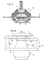
- this anti-vibration support can be of the type shown in FIG. 3, known from document EP-A-0 346 227, in which the elastomer body 13 has a bell shape extending by diverging from a summit united with the first frame 11 up to an annular base secured to the second frame 12, this elastomer body partially delimiting a working chamber A which communicates via a choked passage 17 with a clearing house B delimited by an elastomer bellows 18, the work A, clearing house B and passage constricted 17 forming a sealed volume filled with liquid.
- vibrational movements between the block powertrain 2 and chassis 3 and in particular relatively large vibrational movements (for example example greater than 0.1 mm) and relatively low frequency (e.g. less than 20 Hz), cause liquid movements between chambers A and B by through the strangled passage 17, which causes a particularly effective damping of said movements vibrational.
- relatively large vibrational movements for example example greater than 0.1 mm
- relatively low frequency e.g. less than 20 Hz
- the fixing device 4 of the prior art which has just been described generally works satisfactorily, in particular thanks to the remarkable efficiency of hydraulic antivibration support 10 which has just been described.
- These two limiting rings are each located in a horizontal plane, or more generally in a plane perpendicular to the fingers 16a, 25, 26.
- these limiting rings can for example each have a general oval shape which extends longitudinally in the direction of the X axis between two ends each forming an eyelet which delimits a hole, respectively 30, 31, 32, the fingers 16a, 23, 24 being respectively forcibly fitted each in one of these holes.
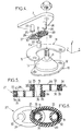
- the double limiting ring 27 comprises a body in single elastomer 33 which is common to the first and second limiting rings 28, 29.
- the two limiting rings 28, 29 could be two separate rooms, without depart from the scope of the invention.
- the double limiter ring 27 is armed by a winding 34 of flexible but substantially inextensible wire (i.e. less stretchy than rubber), by example of polyester yarn.
- This winding 34 forms two loops of wire, either a first loop included inside the first ring limiter 28 and passing outside the fingers 16a and 23, and a second loop included inside the second limiting ring 29 and passing outside the fingers 16a and 24.
- Each loop can for example comprise around 40 yarn towers, with the most common polyester yarns used.
- the two wire loops are made with the same continuous polyester thread.
- an armature rigid 35 metallic or plastic, in order to allow a good distribution of forces between the winding of wire 34 and the body 33 of elastomer.
- the elastomer body 33 has parts 36 interposed between the frames 35 and fingers 16a, 23, 24, in order to obtain good progressiveness in limiting the movements of the power train, that is to say in order to prevent this powertrain is subjected to strong shocks when limiting its deflections.
- oval shape of the two limiting rings 28, 29 participates also to this progressiveness in the limitation of deflections.
- the entire fixing device 4 when submitting the support arm 7 at a force parallel to the X axis of between 500 and 2,000 N., the entire fixing device 4 has a low ratio between on the one hand its overall elastic stiffness Kz parallel to the Z axis and on the other hand its stiffness overall elastic Kx parallel to the X axis, this ratio generally being between 0.1 and 0.15 depending the applied effort, which is excellent value and significantly lower than the values obtained with prior art fasteners such as that shown in Figure 2, where the Kz / Kx ratio was around 0.2.
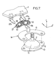
- the support fingers 16b, 23a, 24a, which are engaged respectively in the holes 30, 31, 32 of the double limiter ring 27 can extend along the Y axis, in which case the two limiting rings 28, 29 are each included in a plane vertical parallel to the X axis.
- the three fingers are not necessarily aligned, provided that the two fingers secured to the support 7 are aligned parallel to the X axis and included in respective planes perpendicular to the X axis and arranged on either side of the finger secured to the chassis 3 of the vehicle.
- the two rings 28, 29 of the double limiter ring 27 have non-parallel longitudinal directions, making an angle between them generally greater than 90 degrees.
- the three fingers to which the double is connected limiter ring 27 could be part of pieces different from those described above provided that one of these fingers is integral, directly or indirectly, of one of the arm 7 or of the chassis 3, while the two others of these fingers, framing the first finger, are integral with the other of the arm 7 and the chassis 3.
- one fingers supporting the double limiting ring 27 could be constituted by the first frame 11 of the support antivibration 10, this frame 11 then having preferably an annular groove which receives the end common of the two limiting rings 28, 29.
- the other two fingers around which pass the first and second rings respectively limiters 28, 29 can be formed by two fingers rigid verticals 37, 38, integral with the second frame 12 of the anti-vibration mount 10.
Landscapes
- Engineering & Computer Science (AREA)
- Mechanical Engineering (AREA)
- Chemical & Material Sciences (AREA)
- Combustion & Propulsion (AREA)
- Transportation (AREA)
- General Engineering & Computer Science (AREA)
- Arrangement Or Mounting Of Propulsion Units For Vehicles (AREA)
- Vibration Prevention Devices (AREA)
- Vehicle Body Suspensions (AREA)
Description
- un bras de support rigide solidaire du bloc motopropulseur, le bras de support et le châssis étant appelés ci-après l'un "premier élément" et l'autre "deuxième élément",
- un support antivibratoire qui comprend lui-même une première armature rigide fixée au bras de support, une deuxième armature rigide fixée au châssis et un corps en élastomère reliant entre elles les première et deuxième armatures et supportant le bloc motopropulseur en autorisant les débattements relatifs susmentionnés entre ce bloc motopropulseur et le châssis,
- et un limiteur de débattement qui est apte à limiter les déplacements relatifs entre le bloc motopropulseur et le châssis parallèlement au deuxième axe, le limiteur de débattement comprenant un premier doigt rigide qui s'étend selon une direction perpendiculaire au deuxième axe et qui est solidaire du premier élément.
- des deuxième et troisième doigts rigides qui s'étendent chacun selon une direction longitudinale parallèle à la direction longitudinale du premier doigt et qui sont solidaires du deuxième élément, les deuxième et troisième doigts étant compris dans deux plans perpendiculaires au deuxième axe qui sont situés de part et d'autre du premier doigt,
- et des premier et deuxième anneaux limiteurs comportant chacun un enroulement de fil résistant, flexible mais sensiblement inextensible, enrobé par une gaine en élastomère, le premier anneau limiteur étant fixé aux premier et deuxième doigts avec son enroulement de fil résistant passé autour de l'ensemble des premier et deuxième doigts, et le deuxième anneau limiteur étant fixé aux premier et troisième doigts avec son enroulement de fil résistant passé autour de l'ensemble des premier et troisième doigts.
- les premier et deuxième anneaux limiteurs constituent une seule pièce en élastomère armée de fil résistant;
- les enroulements de fil résistant des premier et deuxième anneaux limiteurs sont constitués par un même fil continu ;
- chaque anneau limiteur comporte des armatures rigides qui sont noyées dans sa gaine en élastomère et qui sont interposées entre l'enroulement de fil résistant de cet anneau limiteur et chacun des doigts auxquels est relié ledit anneau limiteur ;
- chaque anneau limiteur forme deux oeillets qui sont engagés avec frottement respectivement sur les deux doigts auxquels est relié ledit anneau limiteur ;
- les doigts présentent chacun une extrémité libre formant une tête élargie, les têtes élargies des trois doigts empêchant les anneaux limiteurs de se dégager desdits doigts ;
- le premier doigt est constitué par la première armature du support anvibratoire, tandis que les deuxième et troisième doigts sont solidaires du châssis du véhicule ;
- le bras de support s'étend depuis le bloc motopropulseur jusqu'à une extrémité fixée à la première armature du support antivibratoire, et ledit bras de support comporte une partie intermédiaire qui est située entre le bloc motopropulseur et ladite extrémité et qui est solidaire soit du premier doigt, soit des deuxième et troisième doigts ;
- le corps en élastomère du support antivibratoire présente une forme de cloche s'étendant en divergeant depuis un sommet solidaire de la première armature jusqu'à une base annulaire solidaire de la deuxième armature, ce corps en élastomère délimitant partiellement une chambre de travail qui communique par l'intermédiaire d'un passage étranglé avec une chambre de compensation délimitée par une paroi aisément déformable, la chambre de travail, la chambre de compensation et le passage étranglé formant un volume étanche rempli de liquide ;
- le bloc motopropulseur est à suspension pendulaire, ce bloc motopropulseur s'étendant longitudinalement selon un troisième axe horizontal perpendiculaire au deuxième axe et étant relié au châssis par le premier dispositif de fixation associé à des deuxième et troisième dispositifs de fixation, les premier et deuxième dispositifs de fixation étant sensiblement alignés parallèlement au troisième axe et étant fixés au bloc motopropulseur en des points situés au-dessus du niveau du centre de gravité de ce bloc motopropulseur, et le troisième dispositif de fixation étant relié au bloc motopropulseur en un point situé au-dessous des premier et deuxième dispositifs de fixation.
- la figure 1 montre très schématiquement un moteur de véhicule automobile à suspension pendulaire, connu en soi,
- la figure 2 est une vue également très schématique d'un véhicule automobile de l'art antérieur équipé d'un moteur tel que celui de la figure 1, cette figure montrant plus en détail l'un des dispositifs de fixation du moteur,
- la figure 3 est une vue en coupe verticale d'un support antivibratoire hydraulique, connu en soi, appartenant au dispositif de fixation montré sur la figure 2,
- la figure 4 est une vue éclatée d'un dispositif de fixation pour moteur selon une forme de réalisation de l'invention, destiné à remplacer le dispositif de fixation de l'art antérieur représenté sur la figure 2,
- la figure 5 est une vue en coupe transversale d'un double anneau limiteur en élastomère appartenant au dispositif de fixation de la figure 4,
- la figure 6 est une vue en coupe selon la ligne VI-VI de la figure 5,
- la figure 7 est une vue éclatée et écorchée d'un dispositif de fixation pour moteur utilisable dans une deuxième forme de réalisation de l'invention,
- et la figure 8 est une vue schématique d'un dispositif de fixation pour moteur selon encore une autre forme de réalisation de l'invention.
- des premier et deuxième dispositifs de fixation 4, 5 alignés parallèlement à l'axe Y et fixés aux extrémités longitudinales du bloc motopropulseur en des points situés au-dessus du centre de gravité G de ce bloc motopropulseur,
- et un troisième dispositif de fixation 6 relié au bloc motopropulseur en un point situé au dessous des premier et deuxième dispositifs de fixation, par exemple sur un des côtés du bloc motopropulseur ou au dessous de ce bloc motopropulseur.
- un bras de support rigide 7 sensiblement horizontal, qui est généralement réalisé en aluminium moulé ou en fonte et qui est fixé à une extrémité longitudinale du bloc motopropulseur 2, en l'occurence à l'opposé de la boíte de vitesses 8 de ce bloc motopropulseur, ce bras de support 7 étant traversé verticalement par un évidement 9 situé dans une position sensiblement médiane entre les deux extrémités dudit bras 7,
- un support antivibratoire 10 qui dans tous les cas comprend une première armature rigide 11 fixée sous le bras de support 7, une deuxième armature rigide 12 fixée au châssis 3, et un corps en élastomère 13 reliant entre elles les première et deuxième armatures et supportant le bloc motopropulseur 2 en autorisant les débattements relatifs susmentionnés entre ce bloc motopropulseur et le châssis,
- et un limiteur de débattement 14 qui est apte à limiter les déplacements relatifs entre le bloc motopropulseur 2 et le châssis 3 parallèlement à l'axe X (c'est-à-dire non seulement en translation selon l'axe X, mais également en rotation autour de l'axe Y, puisqu'une telle rotation provoque un déplacement selon les axes X et Z de tout point du bloc motopropulseur non situé sur l'axe de rotation).
- le support antivibratoire 10 est identique ou similaire à celui décrit précédemment,
- le limiteur 14 comporte toujours une plaque de base 15 identique à celle décrite précédemment, mais le doigt vertical 16 est remplacé par un doigt vertical 16a plus court et présentant de préférence à son extrémité libre une tête 22 formant un léger élargissement,
- le bras de support 7 est similaire au bras déjà décrit, mais ne comporte pas l'évidement 9, ledit bras 7 comportant, en revanche, deux doigts rigides verticaux 23, 24 qui s'étendent vers le bas à partir de la face inférieure du bras 7 et qui présentent chacun de préférence une extrémité libre dotée d'une tête 25, 26 formant un léger élargissement, les trois doigts 16a, 23, 24 étant disposés dans un même plan vertical parallèle à l'axe X, et l'extrémité libre du doigt 16a étant située au-dessus des extrémités libres des doigts 23, 24,
- et le doigt 16a est relié aux doigts 23 et 24 par un double anneau limiteur 27 en élastomère constitué par des premier et deuxième anneaux limiteurs 28, 29.
Claims (10)
- Véhicule automobile comportant un châssis (3), un bloc motopropulseur (2) et une pluralité de dispositifs de fixation (4,5,6) supportant le bloc motopropulseur (2) et amortissant les mouvements vibratoires relatifs entre le bloc motopropulseur (2) et le châssis (3) parallèlement à un premier axe (Z) sensiblement vertical, ces dispositifs de fixation (4,5,6) autorisant des débattements du bloc motopropulseur (2) par rapport au châssis (3) parallèlement au premier axe (Z) et au moins parallèlement à un deuxième axe (X) perpendiculaire au premier axe, au moins un de ces dispositifs de fixation, dit "premier dispositif de fixation" (4), comprenant :caractérisé en ce que le limiteur de débattement (14) comprend en outre :un bras de support (7) rigide solidaire du bloc motopropulseur (2), le bras de support (7) et le châssis (3) étant appelés ci-après l'un "premier élément" et l'autre "deuxième élément",un support antivibratoire (10) qui comprend lui-même une première armature rigide (11) fixée au bras de support (7), une deuxième armature rigide (12) fixée au châssis (3) et un corps en élastomère (13) reliant entre elles les première et deuxième armatures (11 et 12) et supportant le bloc motopropulseur (2) en autorisant les débattements relatifs susmentionnés entre ce bloc motopropulseur (2) et le châssis (3),et un limiteur de débattement (14) qui est apte à limiter les déplacements relatifs entre le bloc motopropulseur (2) et le châssis (3) parallèlement au deuxième axe (X), le limiteur de débattement comprenant un premier doigt (16a;16b;11) rigide qui s'étend selon une direction perpendiculaire au deuxième axe (X) et qui est solidaire du premier élément,des deuxième et troisième doigts rigides (23;23a;37 et 24;24a;38) qui s'étendent chacun selon une direction longitudinale parallèle à la direction longitudinale du premier doigt (16a;16b;11) et qui sont solidaires du deuxième élément, les deuxième et troisième doigts (23;23a;37 et 24;24a;38) étant compris dans deux plans perpendiculaires au deuxième axe (X) qui sont situés de part et d'autre du premier doigt (16a;16b;11),et des premier et deuxième anneaux limiteurs (28 et 29) comportant chacun un enroulement (34) de fil résistant, flexible mais sensiblement inextensible, enrobé par une gaine en élastomère (33), le premier anneau limiteur (28) étant fixé aux premier et deuxième doigts (16a;16b;11 et 23;23a;37) avec son enroulement de fil résistant passé autour de l'ensemble des premier et deuxième doigts, et le deuxième anneau limiteur (29) étant fixé aux premier et troisième doigts (16a;16b;11 et 24;24a;38) avec son enroulement de fil résistant passé autour de l'ensemble des premier et troisième doigts.
- Véhicule selon la revendication 1, dans lequel les premier et deuxième anneaux limiteurs (28 et 29) constituent une seule pièce en élastomère (27) armée de fil résistant (34).
- Véhicule selon la revendication 2, dans lequel les enroulements de fil résistant (34) des premier et deuxième anneaux limiteurs (28 et 29) sont constitués par un même fil continu.
- Véhicule automobile selon l'une quelconque des revendications précédentes, dans lequel chaque anneau limiteur (28,29) comporte des armatures rigides (35) qui sont noyées dans sa gaine en élastomère (33) et qui sont interposées entre l'enroulement de fil résistant (34) de cet anneau limiteur et chacun des doigts (16a,16b,23,23a, 24,24a,11,37,38) auxquels est relié ledit anneau limiteur.
- Véhicule selon l'une quelconque des revendications précédentes, dans lequel chaque anneau limiteur (28,29) forme deux oeillets (30,31,32) qui sont engagés avec frottement respectivement sur les deux doigts (16a,16b, 23,23a,24,24a,11,37,38) auxquels est relié ledit anneau limiteur.
- Véhicule selon la revendication 5, dans lequel les trois doigts (16a,23,24) présentent chacun une extrémité libre formant une tête élargie (22,25,26), les têtes élargies des trois doigts empêchant les anneaux limiteurs (28,29) de se dégager desdits doigts.
- Véhicule selon l'une quelconque des revendications précédentes, dans lequel le premier doigt (11) est constitué par la première armature du support anvibratoire (10), tandis que les deuxième et troisième (37 et 38) doigts sont solidaires du châssis (3) du véhicule.
- Véhicule selon l'une quelconque des revendications 1 à 6, dans lequel le bras de support (7) s'étend depuis le bloc motopropulseur (2) jusqu'à une extrémité fixée à la première armature (11) du support antivibratoire, et ledit bras de support comporte une partie intermédiaire qui est située entre le bloc motopropulseur et ladite extrémité et qui est solidaire soit du premier doigt (16a;16b), soit des deuxième et troisième doigts (23 et 24; 23a et 24a) (Fig.7).
- Véhicule selon l'une quelconque des revendications précédentes, dans lequel le corps en élastomère (13) du support antivibratoire (10) présente une forme de cloche s'étendant en divergeant depuis un sommet solidaire de la première armature (11) jusqu'à une base annulaire solidaire de la deuxième armature (12), ce corps en élastomère délimitant partiellement une chambre de travail (A) qui communique par l'intermédiaire d'un passage étranglé (17) avec une chambre de compensation (B) délimitée par une paroi (18) aisément déformable, la chambre de travail, la chambre de compensation et le passage étranglé formant un volume étanche rempli de liquide.
- Véhicule selon l'une quelconque des revendications précédentes, dans lequel le bloc motopropulseur (2) est à suspension pendulaire, ce bloc motopropulseur s'étendant longitudinalement selon un troisième axe (Y) horizontal perpendiculaire au deuxième axe (X) et étant relié au châssis (3) par le premier dispositif de fixation (4) associé à des deuxième et troisième dispositifs de fixation (5 et 6), les premier et deuxième dispositifs de fixation (4 et 5) étant sensiblement alignés parallèlement au troisième axe (Y) et étant fixés au bloc motopropulseur en des points situés au-dessus du niveau du centre de gravité (G) de ce bloc motopropulseur, et le troisième dispositif de fixation (6) étant relié au bloc motopropulseur en un point situé au-dessous des premier et deuxième dispositifs de fixation.
Applications Claiming Priority (2)
| Application Number | Priority Date | Filing Date | Title |
|---|---|---|---|
| FR9613739 | 1996-11-12 | ||
| FR9613739A FR2755648B1 (fr) | 1996-11-12 | 1996-11-12 | Vehicule automobile comportant un bloc motopropulseur dote d'une suspension a debattement limite |
Publications (2)
| Publication Number | Publication Date |
|---|---|
| EP0841204A1 EP0841204A1 (fr) | 1998-05-13 |
| EP0841204B1 true EP0841204B1 (fr) | 2000-06-07 |
Family
ID=9497516
Family Applications (1)
| Application Number | Title | Priority Date | Filing Date |
|---|---|---|---|
| EP97402673A Expired - Lifetime EP0841204B1 (fr) | 1996-11-12 | 1997-11-07 | Véhicule automobile comportant un bloc motopropulseur doté d'une suspension à débattement limité |
Country Status (7)
| Country | Link |
|---|---|
| US (1) | US5947226A (fr) |
| EP (1) | EP0841204B1 (fr) |
| AR (1) | AR013871A1 (fr) |
| BR (1) | BR9704517A (fr) |
| DE (1) | DE69702232T2 (fr) |
| ES (1) | ES2148918T3 (fr) |
| FR (1) | FR2755648B1 (fr) |
Families Citing this family (13)
| Publication number | Priority date | Publication date | Assignee | Title |
|---|---|---|---|---|
| CA2264401C (fr) * | 1998-05-11 | 2003-01-28 | Rheem Manufacturing Company | Appareil pour installer un support precontraint de compresseur et methodes connexes |
| FR2809996B1 (fr) * | 2000-06-08 | 2002-10-11 | C F Gomma Barre Thomas | Support de suspension a debattement limite pour groupe motopropulseur et engin motorise muni d'un tel support |
| FR2831630B1 (fr) * | 2001-10-29 | 2004-01-30 | Hutchinson | Support antivibratoire hydraulique comportant un clapet de decouplage clipse |
| KR100489110B1 (ko) * | 2002-03-25 | 2005-05-12 | 현대자동차주식회사 | 자동차의 엔진 마운팅 구조 |
| JP2004100789A (ja) * | 2002-09-06 | 2004-04-02 | Honda Motor Co Ltd | 車両の動力源マウント構造 |
| JP4367077B2 (ja) * | 2003-10-09 | 2009-11-18 | 日産自動車株式会社 | 駆動モータ取付構造 |
| JP4637715B2 (ja) * | 2005-10-17 | 2011-02-23 | 日信工業株式会社 | 車両用支持構造体の製造方法 |
| DE102006039106A1 (de) * | 2006-08-19 | 2008-02-21 | Daimler Ag | Vorrichtung zum Antreiben eines Brennstoffzellen-Fahrzeuges |
| US7975787B2 (en) * | 2008-11-06 | 2011-07-12 | Clark Equipment Company | Low mount three point engine and pump mounting |
| SE537132C2 (sv) * | 2013-05-30 | 2015-02-10 | BAE Systems Hägglunds Aktiebolag | Elektrisk drivanordning för drivning av ett motorfordon |
| FR3077778B1 (fr) * | 2018-02-09 | 2020-01-17 | Psa Automobiles Sa | Systeme de traction electrique pour vehicule avec un groupe motopropulseur fixe sous une traverse |
| FI12778Y1 (fi) * | 2019-11-25 | 2020-09-30 | Labrys Oy | Jousielementti |
| FR3108067B1 (fr) * | 2020-03-13 | 2022-12-23 | Psa Automobiles Sa | Limiteur de debattement pour un groupe motopropulseur de vehicule automobile |
Family Cites Families (9)
| Publication number | Priority date | Publication date | Assignee | Title |
|---|---|---|---|---|
| JPS524624U (fr) * | 1975-06-25 | 1977-01-13 | ||
| CA1226230A (fr) * | 1983-11-23 | 1987-09-01 | Richard A. Muzechuk | Support elastomere hydraulique |
| DE3402401A1 (de) * | 1984-01-25 | 1985-07-25 | Adam Opel AG, 6090 Rüsselsheim | Lageranordnung, insbesondere motorlager fuer kraftfahrzeuge |
| DE3737988A1 (de) * | 1987-11-09 | 1989-05-24 | Draebing Kg Wegu | Lager fuer motor, getriebe oder aehnliche teile eines kraftfahrzeugs |
| DE8714888U1 (de) * | 1987-11-09 | 1988-02-04 | WEGU Gummi- und Kunststoffwerke Walter Dräbing KG, 34123 Kassel | Aufhängeöse für eine Abgasanlage eines Kraftfahrzeugs |
| FR2632696B1 (fr) | 1988-06-09 | 1993-10-01 | Hutchinson | Perfectionnements aux dispositifs antivibratoires hydrauliques |
| US4896797A (en) * | 1989-01-17 | 1990-01-30 | Tumlin Bruce A | Seed stick |
| JP2843088B2 (ja) * | 1990-02-02 | 1999-01-06 | 東海ゴム工業株式会社 | 流体封入式マウント装置 |
| FR2694792B1 (fr) * | 1992-08-14 | 1994-10-21 | Hutchinson | Biellette de reprise de couple pour moteur de véhicule. |
-
1996
- 1996-11-12 FR FR9613739A patent/FR2755648B1/fr not_active Expired - Fee Related
-
1997
- 1997-11-07 ES ES97402673T patent/ES2148918T3/es not_active Expired - Lifetime
- 1997-11-07 DE DE69702232T patent/DE69702232T2/de not_active Expired - Fee Related
- 1997-11-07 EP EP97402673A patent/EP0841204B1/fr not_active Expired - Lifetime
- 1997-11-10 US US08/966,933 patent/US5947226A/en not_active Expired - Fee Related
- 1997-11-11 BR BR9704517A patent/BR9704517A/pt not_active IP Right Cessation
- 1997-11-11 AR ARP970105238A patent/AR013871A1/es unknown
Also Published As
| Publication number | Publication date |
|---|---|
| MX9708734A (es) | 1998-06-28 |
| BR9704517A (pt) | 1998-09-08 |
| US5947226A (en) | 1999-09-07 |
| FR2755648A1 (fr) | 1998-05-15 |
| ES2148918T3 (es) | 2000-10-16 |
| FR2755648B1 (fr) | 1999-01-15 |
| DE69702232D1 (de) | 2000-07-13 |
| AR013871A1 (es) | 2001-01-31 |
| EP0841204A1 (fr) | 1998-05-13 |
| DE69702232T2 (de) | 2001-01-04 |
Similar Documents
| Publication | Publication Date | Title |
|---|---|---|
| EP0223712B1 (fr) | Perfectionnements aux amortisseurs hydrauliques | |
| EP0735294B1 (fr) | Articulation élastique notamment pour un train roulant de véhicule automobile | |
| EP0841204A1 (fr) | Véhicule automobile comportant un bloc motopropulseur doté d'une suspension à débattement limité | |
| EP0410896B1 (fr) | Perfectionnements aux dispositifs amortisseurs de vibrations | |
| EP1816371A1 (fr) | Support antivibratoire hydraulique et son procédé de fabrication | |
| FR2670552A1 (fr) | Attache hydroelastique de suspension et biellette de liaison geometrique liee a cette attache. | |
| EP1217249A1 (fr) | Manchon antivibratoire et véhicule automobile comportant un tel manchon | |
| EP1132645B1 (fr) | Dispositif élastique de suspension d'une structure vibrante à une structure rigide | |
| EP0409707A1 (fr) | Perfectionnements aux dispositifs antivibratoires hydrauliques | |
| EP0270456B1 (fr) | Dispositif de suspension de la caisse et du groupe motopropulseur d'un véhicule automobile | |
| EP0225227B1 (fr) | Perfectionnements aux supports antivibratiores hydrauliques | |
| EP0236161B1 (fr) | Cale hydroélastique à suspension centrale, notamment pour la suspension d'un groupe motopropulseur de véhicule automobile | |
| EP0255434A1 (fr) | Perfectionnements aux supports amortisseurs hydrauliques | |
| EP2282076B1 (fr) | Dispositif de liaison antivibratoire pour véhicule et véhicule comportant un tel dispositif | |
| EP0894995B1 (fr) | Support antivibratoire hydraulique | |
| EP1043514B1 (fr) | Dispositif antivibratoire de reprise de couple | |
| FR2809996A1 (fr) | Support de suspension a debattement limite pour groupe motopropulseur et engin motorise muni d'un tel support | |
| EP0656486B1 (fr) | Perfectionnement aux dispositifs antivibratoires hydrauliques | |
| FR2655113A1 (fr) | Dispositif d'amortissement en elastomere rempli d'un fluide. | |
| EP4040005A1 (fr) | Support antivibratoire et vehicule comportant un tel support antivibratoire | |
| EP1682371B1 (fr) | Dispositif de fixation d un groupe motopropulseur a un chassis de vehicule au moyen d'une biellette | |
| FR2671839A1 (fr) | Perfectionnements aux supports antivibratoires hydrauliques. | |
| EP1663689B1 (fr) | Support elastique notamment pour lignes d echappement de veh icule automobile | |
| FR2812242A1 (fr) | Essieu deformable a suspension integree pour vehicule automobile | |
| FR2755649A1 (fr) | Vehicule automobile comportant un bloc motopropulseur dote d'une suspension a debattement limite |
Legal Events
| Date | Code | Title | Description |
|---|---|---|---|
| PUAI | Public reference made under article 153(3) epc to a published international application that has entered the european phase |
Free format text: ORIGINAL CODE: 0009012 |
|
| AK | Designated contracting states |
Kind code of ref document: A1 Designated state(s): DE ES GB IT |
|
| AX | Request for extension of the european patent |
Free format text: AL;LT;LV;MK;RO;SI |
|
| 17P | Request for examination filed |
Effective date: 19980713 |
|
| AKX | Designation fees paid |
Free format text: DE ES GB IT |
|
| RBV | Designated contracting states (corrected) |
Designated state(s): DE ES GB IT |
|
| GRAG | Despatch of communication of intention to grant |
Free format text: ORIGINAL CODE: EPIDOS AGRA |
|
| GRAG | Despatch of communication of intention to grant |
Free format text: ORIGINAL CODE: EPIDOS AGRA |
|
| GRAH | Despatch of communication of intention to grant a patent |
Free format text: ORIGINAL CODE: EPIDOS IGRA |
|
| 17Q | First examination report despatched |
Effective date: 19991022 |
|
| GRAH | Despatch of communication of intention to grant a patent |
Free format text: ORIGINAL CODE: EPIDOS IGRA |
|
| GRAA | (expected) grant |
Free format text: ORIGINAL CODE: 0009210 |
|
| AK | Designated contracting states |
Kind code of ref document: B1 Designated state(s): DE ES GB IT |
|
| REF | Corresponds to: |
Ref document number: 69702232 Country of ref document: DE Date of ref document: 20000713 |
|
| ITF | It: translation for a ep patent filed | ||
| GBT | Gb: translation of ep patent filed (gb section 77(6)(a)/1977) |
Effective date: 20000818 |
|
| REG | Reference to a national code |
Ref country code: ES Ref legal event code: FG2A Ref document number: 2148918 Country of ref document: ES Kind code of ref document: T3 |
|
| PLBE | No opposition filed within time limit |
Free format text: ORIGINAL CODE: 0009261 |
|
| STAA | Information on the status of an ep patent application or granted ep patent |
Free format text: STATUS: NO OPPOSITION FILED WITHIN TIME LIMIT |
|
| 26N | No opposition filed | ||
| REG | Reference to a national code |
Ref country code: GB Ref legal event code: IF02 |
|
| PGFP | Annual fee paid to national office [announced via postgrant information from national office to epo] |
Ref country code: ES Payment date: 20071119 Year of fee payment: 11 Ref country code: DE Payment date: 20071108 Year of fee payment: 11 |
|
| PGFP | Annual fee paid to national office [announced via postgrant information from national office to epo] |
Ref country code: IT Payment date: 20071115 Year of fee payment: 11 |
|
| PGFP | Annual fee paid to national office [announced via postgrant information from national office to epo] |
Ref country code: GB Payment date: 20071114 Year of fee payment: 11 |
|
| GBPC | Gb: european patent ceased through non-payment of renewal fee |
Effective date: 20081107 |
|
| PG25 | Lapsed in a contracting state [announced via postgrant information from national office to epo] |
Ref country code: IT Free format text: LAPSE BECAUSE OF NON-PAYMENT OF DUE FEES Effective date: 20081107 |
|
| PG25 | Lapsed in a contracting state [announced via postgrant information from national office to epo] |
Ref country code: DE Free format text: LAPSE BECAUSE OF NON-PAYMENT OF DUE FEES Effective date: 20090603 |
|
| PG25 | Lapsed in a contracting state [announced via postgrant information from national office to epo] |
Ref country code: GB Free format text: LAPSE BECAUSE OF NON-PAYMENT OF DUE FEES Effective date: 20081107 |
|
| REG | Reference to a national code |
Ref country code: ES Ref legal event code: FD2A Effective date: 20081108 |
|
| PG25 | Lapsed in a contracting state [announced via postgrant information from national office to epo] |
Ref country code: ES Free format text: LAPSE BECAUSE OF NON-PAYMENT OF DUE FEES Effective date: 20081108 |