EP0840960B1 - Method and apparatus for cdma signal orthogonalization - Google Patents
Method and apparatus for cdma signal orthogonalization Download PDFInfo
- Publication number
- EP0840960B1 EP0840960B1 EP96924518A EP96924518A EP0840960B1 EP 0840960 B1 EP0840960 B1 EP 0840960B1 EP 96924518 A EP96924518 A EP 96924518A EP 96924518 A EP96924518 A EP 96924518A EP 0840960 B1 EP0840960 B1 EP 0840960B1
- Authority
- EP
- European Patent Office
- Prior art keywords
- signal
- composite signal
- signature
- sequence
- signature sequences
- Prior art date
- Legal status (The legal status is an assumption and is not a legal conclusion. Google has not performed a legal analysis and makes no representation as to the accuracy of the status listed.)
- Expired - Lifetime
Links
Images


Classifications
-
- H—ELECTRICITY
- H04—ELECTRIC COMMUNICATION TECHNIQUE
- H04B—TRANSMISSION
- H04B1/00—Details of transmission systems, not covered by a single one of groups H04B3/00 - H04B13/00; Details of transmission systems not characterised by the medium used for transmission
- H04B1/69—Spread spectrum techniques
- H04B1/707—Spread spectrum techniques using direct sequence modulation
- H04B1/7097—Interference-related aspects
- H04B1/7103—Interference-related aspects the interference being multiple access interference
- H04B1/7107—Subtractive interference cancellation
-
- H—ELECTRICITY
- H04—ELECTRIC COMMUNICATION TECHNIQUE
- H04J—MULTIPLEX COMMUNICATION
- H04J13/00—Code division multiplex systems
- H04J13/10—Code generation
- H04J13/12—Generation of orthogonal codes
Description
- The present invention generally relates to radio communications systems and more particularly, to minimizing the effects of multiple access interference in a Direct-Sequence Code Division Multiple Access (DS-CDMA) communications system.
- Direct-sequence Code Division Multiple Access (DS-CDMA) techniques are being applied to cellular and personal radio communication systems. With such an approach, all signals share the same frequency spectrum at the same time. For example, suppose that user i conveys an information symbol bi by transmitting bisi(k), the product of the information symbol b; and the code or signature sequence si(k). By using different signature sequences for different users, the information symbol of a particular user may be determined by correlating the received signal with the user's known signature sequence. Because these codes are rarely orthogonal, the separation is not perfect, so that signals interfere with one another, thereby degrading performance.
- One method for dealing with interference in CDMA systems is to perform some form of subtractive demodulation, where each signal, starting with the strongest, is demodulated then subtracted from the composite received signal. If the correct amplitude and phase of each signal is known, as well as the information symbol value, then subtraction is perfect, and only the particular signal of interest is subtracted. Such an approach is described in A. J. Viterbi, "Very low rate convolutional codes for maximum theoretical performance of spread-spectrum multiple-access channels," IEEE J. Select. Areas Commun., vol. 8, pp. 641-649, May 1990.
- In practice, the amplitude, phase and symbol values are either unknown or must be estimated, giving rise to estimation noise which leads to subtraction error. One way of estimating these values is to correlate the received data with the known signature sequence. When subtraction occurs, this approach effectively nulls out all components of the received signal that arc aligned with the signal being removed, including a small amount of all the other signals. This form of subtractive demodulation is described in U. S. Patents 5,151,919 and 5,218,619 to Dent.
- Parallel as well serial subtraction is possible. U.S. Patent No. 5,345,472 describes a technique for estimating signature sequences in a CDMA receiver.
- Because the amplitude, phase, and symbol estimation are noisy, subtraction error occurs, which can accumulate to the detriment of performance. In particular, it has been observed that when the second signal is removed, noise appears in the resultant signal that is aligned with the first signal that was removed. Similarly, when the third signal is removed, noise appears that is aligned with the first two signals. Thus, there is a need for a way to eliminate or minimize the noise introduced by the subtraction process.
- These and other drawbacks and limitations of conventional CDMA demodulation techniques are overcome according to the present invention, wherein a pre-orthogonalization procedure is employed. This procedure can be used, for example, to improve subtraction of CDMA signals from a composite spread spectrum signal or to improve detection of CDMA signals within the composite spread spectrum signal.
- According to exemplary embodiments, a Gram-Schmidt orthogonalization process is used to modify signature sequences which are each associated with a particular CDMA signal in the spread spectrum composite signal. These modified signature sequences can then be used to spread correlations of the original signature sequences with the received composite (e.g., to improve subtraction of each CDMA signal) or in the correlation process to improve detection. Pre-orthogonalization according to the present invention, eliminates or mitigates the creation of noise which can occur when using conventional CDMA demodulation techniques.
- The foregoing, and other objects, features and advantages will be more readily understood upon reading the following detailed description in conjunction with the drawings in which:
- Figure 1 is a geometric illustration of the subtraction process;
- Figure 2 is a block diagram of signal processing according to an exemplary embodiment of the present invention;
- Figure 3 is a block diagram of an exemplary stage processor according to the present invention;
- Figure 4 is a block diagram of another exemplary embodiment of a stage processor;
- Figure 5 is a block diagram of another exemplary embodiment of the present invention;
- Figure 6 is a block diagram of yet another exemplary embodiment of the present invention;
- Figures 7 and 8 each show a transmitter block diagram according to exemplary embodiments of the present invention; and
- Figure 9 illustrates symbol timing according to exemplary embodiments of the present invention.
-
- According to exemplary embodiments of the present invention, a pre-orthogonalization approach is used, which is based in part on the Gram-Schmidt procedure for orthogonalizing sequences. The Gram-Schmidt procedure is described in detail below. Pre-orthogonalization approaches according to the present invention can, for example, be used in two ways. First, these approaches can improve subtraction by reducing subtraction error in a subtractive demodulation receiver. Second, these approaches can be used to improve detection by eliminating interference in the detection process by correlating the received signal to modified signature sequences that are orthogonal with respect to one another.
- An improved subtraction approach is described first using an example, in which the received signal r(n) during a given symbol period is a composite of three signals, so that:
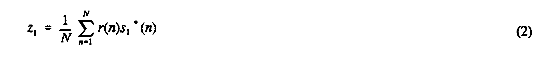
- With conventional subtractive demodulation, the first (strongest) signal would be detected then removed. Detection occurs by correlating the received signal with the complex conjugate of si(n) (the conjugate is not needed if the sequence is real valued, such as ±1). This gives detection statistic z1 which can be expressed as:though the division by N would normally be omitted when implemented to reduce the complexity of the system. The superscript * denotes complex conjugation. This detection statistic can be analyzed by substituting equation (1) in equation (2), giving:
 is the cross-correlation of signature sequences a and b and the superscript "*" denotes complex conjugation. Observe that the first term in equation (3), i.e., c1b1, represents the desired signal, whereas the remaining terms represent interference.
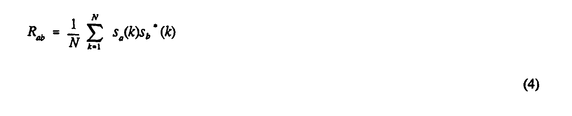
- Demodulation uses the detection statistic z1 to determine the information being conveyed. For example, if c1 is known or estimated and b1 is ±1, then z1 can be multiplied by c1* and the sign of the real part of the product taken as the detected value of b1. If differential modulation is used, then z1 can be multiplied by the conjugate of the previous value of z1 to determine the information sent. In general, the way in which the detection statistic z1 is used to determine the information depends on the type of modulation used and the capabilities of the receiver as will be apparent to those skilled in the art.
- To remove signal 1, the received signal is correlated to s1(n) to give an estimate of the amplitude, phase, and symbol value together. This is the detection statistic z1. So, the received signal with signal 1 removed, i.e., the resultant signal denoted r1, is given by:

- Next, signal 2 is demodulated and removed. The detection statistic for signal 2 is obtained by correlating r1(n) to s2(n), so that:This detection statistic can be analyzed by substituting equations (5), (3), and (1) in equation (7), giving:
 where the property that Rba = Rab* has been used. Two observations can be made from equation (8). First, signal 1 does not interfere with signal 2 as the term c1 is absent in the final expression. Secondly, a part of signal 2 was removed when signal 1 was removed, as evidenced by the subtraction of |R21|2 from the signal term c2b2.
- The second signal is then removed from the spread spectrum composite signal, generating another resultant signal r2(n), as follows:
- This second residual signal has no component aligned along the second signal's signature sequence. However, in forming the second residual signal, energy has been introduced along the first signal's signature sequence. This can be seen by correlating the second residual signal with the first signature sequence, giving:This correlation can be analyzed by substituting equations (9), (8), (5), (3), and (1) in equation (10), giving:
 Observe that x is not necessarily zero, which indicates that energy aligned with the first signal has been introduced. Thus, energy along the first signal is no longer nulled out or zero as it was after the first signal's initial removal at equation (5). This newly introduced energy doesn't depend on the first signal's strength, but does depend on the second and third signals' strengths. Accordingly, when detecting the third signal, interference from the second signal will be present. This can be seen by forming the third signal's detection statistic:
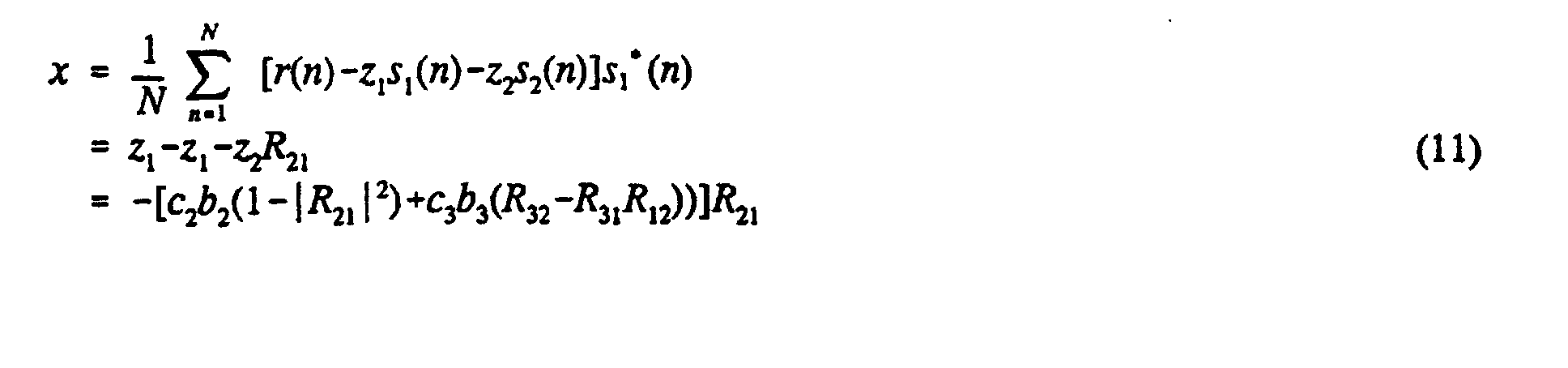 This statistic can be analyzed by substituting equations (9), (8), (5), (3), and (1) in equation (12), giving:
 Note that there is an interference term proportional to c2 in equation (13), implying that the second signal is interfering with the third, even though all energy was nulled out along the second signal's signature sequence by forming r2(n) at equation (9).
- This problem can be viewed geometrically, for example, by thinking of the signals as vectors. In Figure 1, the first two signals (i.e., the strongest two signals in a spread spectrum composite) are shown as vectors v1 and v2. The second signal, v2, is also shown as the sum of two component vectors, one (i.e., vector 10) aligned with the first signal v1 and one (i.e., vector 12) orthogonal to the first signal. When the first signal is removed, the component of the second signal aligned with the first signal is also removed. Thus, vector 10 is removed, leaving vector 12. Vector 12 can also be expressed as the sum of two component vectors, for example a vector 14 aligned with the second signal v2, and a vector 16 orthogonal to the second signal v2. The second signal is removed by removing all components that are aligned with vector v2. Thus, vector 16 is removed, but vector 14 is not, leaving a portion of the second signal in the residual signal. Observe that vector 16 has a nonzero projection onto vector v1, so that part of the second signal residual energy is aligned with the first signal axis.
- From this vector point of view, it would be preferable if, when removing the second signal, all energy along vector 12 is removed rather than all energy along vector v2. This would remove the remaining energy of the second signal which subsequently causes interference. Notice that vector 12 is the part of vector v2 that is orthogonal to vector v1. The Gram-Schmidt procedure can be used to determine this component.
- The Gram-Schmidt procedure is exemplified in section 4.7 of W.L. Brogan, Modem Control Theory, Englewood Cliffs, NJ: Prentice-Hall, 1982. The Gram-Schmidt sequences ui(n) are formed from the original signature sequences si(n) according to the following procedure:
 Observe that
- When subtracting a signal, the Gram-Schmidt sequence may be used, so that the subtraction procedure according to exemplary embodiments of the present invention are given by:

- Thus, according to exemplary embodiments of the present invention, subtraction is performed using detection statistics and modified signature sequences, in which the modified sequences are orthogonal to one another. An illustration of this exemplary embodiment of the invention is now given using the previous example. The first signal is demodulated and removed in the same way as described above, since u1(n) = s1(n). However, the second signal is removed in a different way. Instead of using equation (9), the second residual signal is formed by:
- Now it will be shown that r'2(n) has no component along either signal 1 or signal 2. Computing the correlation of r'2(n) with signal 1, using equation (26),

- Also, computing the correlation of r'2(n) with signal 2, using equation (26),

- Thus, the new residual signal r'2 arrived at by way of signal processing according to this exemplary embodiment of the present invention, has no components along signals 1 and 2. Also, the complex gains c1 and c2 are absent from the final expression for r'2 in equation (26). Thus, when detecting signal 3, interference from signals 1 and 2 is not present.
- An exemplary system for implementing the afore-described signal processing to provide this improved subtraction form of pre-orthogonalization is shown in Figure 2. An antenna 202 receives the radio signal, which is processed by the radio processor 204 to provide complex-valued, baseband chip samples. Radio processing as exemplified by block 204 is well known in the art and includes filtering, amplification, mixing, and sampling operations. The resulting baseband signal is provided to the stage 1 processor 206, which produces a detection statistic for the signal 1, z'1, the strongest signal, and a residual signal, r'1, which represents the received signal with signal 1 removed. This residual signal is provided to a stage 2 processor 208, which is similar to the stage 1 processor, except that it operates with regard to signal 2. Those skilled in the art will appreciate that any number of processing stages can be provided in the receiver of Figure 2, depending on the desired number of signals to be obtained.
- A block diagram of an exemplary stage processor is given in Figure 3. The input to the stage processor is correlated in correlator 302 to a signature sequence provided by sequence generator 304. Because these sequences are typically ±1, the correlator 302 can be implemented using addition and subtraction logic. The output of correlator 302 is the detection statistic z' which is used by the rest of the receiver to determine the information sent on the corresponding signal, and which is also provided to spreader 306, where it is spread with a modified sequence provided by the modified sequence generator 308. The modified sequences ti'(n) can be generated as described above.
- Because the detection statistic and the modified sequence are both nonbinary, e.g., ±1, ±2, ±3, etc., the spreader 306 would normally require multiplications to be performed. The output of spreader 306 is provided to adder 310, which subtracts the output of spreader 306 from the stage processor input that has been delayed by delay unit 312. The output of adder 310 is the residual signal, r'(n).
- An alternative implementation is possible in which the baseband signal is stored in a buffer. When the residual signal is formed, it is used to overwrite the received signal in the buffer. Double buffering can be used, so that part of the data can be processed while more data is being received.
- One implementation concern is the fact that the modified sequences, t'i(n), are not binary. Thus, the spreader 306 multiplies nonbinary chip values with the nonbinary detection statistic N times, i.e., once for each chip sample. The number of multiplications can be reduced by expressing t'i(n) in terms of coefficients aik and the original sequences, so that:
- Thus, subtraction can be performed by first forming only i products, aik z'i for k = 1 to i, then performing subtraction by adding or subtracting these products from each received chip value, depending on the signs of the original signature sequence values. This form of subtraction, in which subtraction of the i'th signal is performed using i subtractions, can either be done sequentially or in parallel.
- A sequential form of this exemplary embodiment of the stage processor is illustrated in Figure 4, where like elements from previous figures are identified using the same reference numeral. The input is correlated in correlator 302 with a signature sequence provided by sequence generator 304. The result is the detection statistic z', which is stored in buffer 402. Then, for one or more iterations, the output of buffer 402 is multiplied in multiplier 404 with a coefficient provided by coefficient generator 406 to produce a product, which is added or subtracted in each element in the controlled accumulator 408, depending on the control information provided by the sequence generator. There are N elements in the controlled accumulator 408, one for each chip sample, which are initially loaded with received chip samples. An iteration is performed for each term on the right side of equation (30). After the iterations are completed, the accumulated result from controlled accumulator 408 is provided as an output.
- A second way to use pre-orthogonalization according to the present invention is for improved detection, so that subtraction of signals can be omitted. The basic idea is to detect the signals using modified signature sequences, using either ti, t'i, or ui. For example, the detection statistic according to this exemplary embodiment would be given by:

- Since the second modified signature sequence is orthogonal to the first sequence, interference from the presence of the first signal is avoided. Similarly, the third modified sequence is orthogonal to the first two.
- An exemplary implementation of this detection form of pre-orthogonalization is shown in Figure 5. Therein, an antenna 202 receives the radio signal, which is processed by the radio processor 204 to provide complex-valued, baseband chip samples. The resulting baseband signal is provided to correlator 502, which correlates to a modified sequence provided by modified sequence generator 504. The result gives detection statistic Z' for a particular signal. Because the received data samples are nonbinary and the modified sequences are nonbinary, the correlator 502 would typically include multipliers. If more than one signal is to be detected, then multiple correlators can be used, either in series or in parallel. Alternatively, the output of the radio processor 204 may be buffered, so that the same correlator can be used repeatedly with different modified sequences corresponding to different signals.
- One implementation concern is the fact that the modified sequences, t'i, ti or ui, are not binary. Thus, the correlator 502 multiplies nonbinary chip values with the nonbinary received data samples N times, i.e., once for each chip sample. The number of multiplications can be reduced by expressing the modified sequence, for example, t'i, in terms of parameters bik and the original sequences s(n), so that:

- Thus, the detection statistic can be obtained by first correlating the data to the original sequences, which can be implemented with additions and subtractions since si(n) are typically ± 1 valued. Then, the final detection statistic is obtained by accumulating y; with only i-1 products, aik yk for k = 1 to i-1. In this way, the number of multiplications can be reduced. This exemplary form of detection, in which detection of the i'th signal is performed using i-1 additions, can either be done sequentially or in parallel.
- Note that the yk values are independent of i, i.e., the signal being detected. In fact, y1 is the detection statistic for the first signal. Also, y2 is needed when computing Z2. Thus, the yk values can be computed once, either in series or in parallel, and stored in a memory device (not shown) in the receiver. Also, the bi,k depend only on the signature sequences, so that they may be pre-computed or computed only rarely. Thus, the i'th detection statistic can be formed by correlating the received signal to the original i'th signature sequence, then adding correlation terms related to previous detection statistics, which would have been stored.
- Another exemplary embodiment for improved detection using pre-orthogonalization according to the present invention, based on parallel correlation but serial detection, is shown in Figure 6. An antenna 202 receives the radio signal, which is processed by the radio processor 204 to provide complex-valued, baseband chip samples. The resulting baseband signal is provided to a bank of correlators 302, which correlate the received signal to the signature sequences provided by sequence generator 304. The results are the correlations yk, which are stored in a buffer 602. To detect a particular signal, a series of products are formed by multiplying outputs of buffer 602 with parameters provided by parameter generator 604 in multiplier 404. These products are accumulated in accumulator 606, which is initialized to zero. To detect another signal, the accumulator would be reset to zero and the multiplying and accumulating operations would be repeated, with parameters corresponding to the other signal.
- In general, subtraction CDMA schemes can be implemented in serial or parallel form. The present invention applies to both such forms. Consider an example in which a group of K signals are be demodulated in parallel. Using the improved detection pre-orthogonalization approach, each signature sequence would be pre-orthogonalized with respect to the other signature sequences in the group. Thus, there would be K Gram-Schmidt procedures, each with a different sequence at the bottom of the list. It will be apparent to one skilled in the art that the present invention may be applied to other forms of parallel subtraction. Also, the technique can be used as the first stage of a recursive demodulation scheme, such as that described in M. K. Varanasi and B. Aazhang, "Multistate detection in asynchronous code-division multiple-access communications," IEEE Trans. Commun., vol. 38, pp. 509-519, Apr. 1990.
- While the examples given so far correspond to one form of DS-CDMA, the present invention is readily applied to other forms of DS-CDMA, as will be apparent to one skilled in the art. In general, an M'ary symbol for user i, denoted bi, can be sent by transmitting one of M possible signature sequences associated with user i, denoted si,k(n). Observe that the examples so far have been a special case, where si,k(n) = bisi(n). In these examples, when components aligned with si(n) are nulled, effectively all components along all si,k(n) are nulled, since all the si,k(n) are proportional to si(n). Thus, nulling does not depend on which symbol is detected, preventing any form of decision feedback error.
- However, for the general case, this is not necessarily so. There are two approaches. In the first approach, only the detected signal is nulled out, so that nulling occurs along the detected si,k(n), but not along the other sequences. This minimizes the number of subtractions, but allows for the possibility that the wrong sequence is nulled out when the wrong symbol is detected. Performance can be improved by delaying subtraction until further processing, such as channel decoding, can be applied to improved detection. There is a special case, when the signal happens to be a known pilot signal, so that the known si,k(n) rather than the detected one can be subtracted.
- With the second approach, nulling occurs on all the si,k(n), regardless of which one was detected. The advantage is that decision error feedback is avoided. The disadvantage is that M subtractions must be performed per signal. Since each subtraction also removes a little bit of the remaining signals, this causes a larger loss of the remaining signal energy. A hybrid approach would be to null out a subset of the si,k(n) sequences, such as the subset that corresponds to the first, second,... best detection statistic.
- Another special case of DS-CDMA is described in the afore-mentioned U.S. Patent No. 5,151,919 to Paul W. Dent. With this approach, Walsh-Hadamard (WH) coding is used to spread the signal, and user's are distinguished by applying a user-specific scrambling mask to the WH codeword. The present invention may be applied to this system using a series of descrambling and fast Walsh transform operations. Since the M possible WH code words span the N dimensional space of a sequence, the second approach of performing M subtractions would not be possible, as this would null out the entire received signal. However, the first approach is possible, in which nulling can be performed in either the Walsh domain or the time domain.
- While pre-orthogonalization at the receiver has been described, it will be readily apparent to one skilled in the art that pre-orthogonalization can be applied at the transmitter, so that the transmitted signals are orthogonal but not necessarily ±1 in value. One interesting case is when a pilot signal is transmitted along with one or more user signals. By pre-orthogonalizing the user signals with respect to the pilot signal, the interference from the user signals is removed, so that the receiver can get a better pilot signal, and hence a better estimate of the channel as well as timing. At the receiving end, the original signature sequences may still be used for detection purposes.
- Another use of pre-orthogonalization at the transmitter would be to avoid interference between cells in a cellular system. The sequences used in one cell, which may already be orthogonal or modified to be orthogonal, could be made orthogonal to sequences used in one or more nearby cells. Thus, modified signature sequences used in nearby cells would not interfere with each other, or they would interfere less with one another.
- An exemplary embodiment of a transmitter using pre-orthogonalization is shown in Figure 7. An information source 702 provides information, typically binary information symbols, that are to be transmitted. These symbols are spread in spreader 704, using modified signature sequences provided by generator 706. The spread signal is modulated in modulator 708 then conveyed to the transmission medium using transmit antenna 710. Typically, a plurality of signals would be transmitted, as illustrated in Figure 8, where like elements with those in Figure 7 use the same reference numeral. A plurality of spread signals are added together in adder 807 prior to modulation and transmission.
- So far, the examples given have been for the case where all user signals are synchronized. There are some situations where this not the case, so that users are asynchronous. An example is given in Figure 9. In this example, the first and second symbols of user A overlap with the first symbol of user B. One way to apply improved subtraction pre-orthogonalization to asynchronous transmissions is as follows. First, both the first and second symbols of user A would be detected and removed from the composite signal. Then, the first symbol of user B would be detected and removed. When removing the first symbol of user B, pre-orthogonalization would be performed with respect to a hybrid sequence for user A, where the hybrid sequence is obtained by taking the latter part of user A's first detected symbol and appending the first part of user A's second detected symbol. With the improved detection scheme, a similar pre-orthogonalization with respect to the hybrid sequence would occur.
- So far, the examples given have been for a frequency-nonselective channel, in which there are no echoes due to time dispersion. In practice, many CDMA systems experience time dispersion. The pre-orthogonalization approach is readily extended to this case. First, detection statistics for each image of the strongest signal, signal A, would be formed, where each image is a ray or echo of the signal . The statistics would then be combined using, for example, Rake combining, to produce an overall statistic for user A. Then, all or some of the rays of signal A would be removed. Then, signal B would be detected. When removing signal B, pre-orthogonalization may occur in a number of ways. First, each ray of signal B may be pre-orthogonalized with respect to all the rays of signal A, and possibly with respect to the other rays of signal B. To reduce complexity, it may be desirable to pre-orthogonalize each ray of signal B with only a subset of the other rays, perhaps even only the ray of signal A that is aligned with the ray of signal B, if it exists. The process then continues for subsequent signals. While this example is based on the subtraction approach according to the present invention, similar examples can be given based on the detection approach.
- In the time dispersion case, pre-orthogonalization may also be used in other ways. First, when forming detection statistics for each image or ray of the signal, detection pre-orthogonalization according to the present invention may be applied to the different shifts of the signature sequence, preventing inter-ray interference or self interference when forming the statistics. Second, when subtracting the rays of a signal, improved subtraction pre-orthogonalization may be applied to the different shifts of the signature sequence to prevent subtraction error from a series of subtractions for one signal. Pre-orthogonalization can also be useful when detecting whether a ray is present or not. For example, known rays can be removed first, and a modified sequence can be used for the detection of possible rays.
- The present invention can be applied to a variety of applications, such as cellular or PCS communication systems. It can also be applied to packet radio systems, such as Aloha-based systems, so that when packet collisions occur, it may still be possible to demodulate more than one packet. While the particular embodiments given use baseband signal processing techniques, it will be readily apparent to one of ordinary skill in the art that the present invention can be applied to intermediate frequency processing techniques, including the use of analog devices. For example, the correlator function may be performed at an intermediate frequency, using a multiplier and a filter.
- Although exemplary embodiments of the present invention have been described and illustrated herein to facilitate understanding of the present invention, it should be understood that the present invention is not limited thereto since modifications may be made by persons skilled in the art. The present application contemplates any and all modifications that fall within the scope of the underlying invention disclosed and claimed herein.
Claims (11)
- A receiver comprising:means (202) for receiving a composite signal, wherein said composite signal comprises at least two particular signals each combined with a different signature sequence;means for processing said composite signal to produce a processed composite signal;means (302) for correlating said processed composite signal with a plurality of signature sequences to produce at least one correlation;means for detecting a particular signal within said composite signal using said at least one correlation;means (308) for modifying each of said plurality of signature sequences to produce a corresponding modified signature sequence, wherein said means for modifying said signature sequences comprises means for orthogonalizing said plurality of signature sequences with respect to others of said plurality of signature sequences;means (306) for spreading said detected particular signal with one of said modified signature sequences; andmeans (310) for removing said particular signal from said processed composite signal using said spread signal.
- The receiver of claim 1, wherein said composite signal is modulated as a direct sequence CDMA signal.
- The receiver of claim 1 or 2, wherein said means for orthogonalizing uses a Gram-Schmidt procedure to orthogonalize each of said plurality of signature sequences.
- A receiver comprising:means (202) for receiving a composite signal, wherein said composite signal comprises at least two particular signals each combined with a different signature sequence;means for processing said composite signal to produce a processed composite signal;means (302) for correlating said processed composite signal with a plurality of signature sequences to produce at least one correlation;means for detecting a particular signal within said composite signal using said at least one correlation;means for generating a modified signature sequence by orthogonalizing a signature sequence associated with said particular signal with respect to others of said plurality of signature sequences; andmeans (408) for removing said particular signal from said processed composite signal by a sequence of subtractions, said sequence of subtractions being performed using coefficients related to the modified signature sequence that corresponds to the signature sequence associated with said particular signal within said composite signal.
- The receiver of claim 4, wherein said composite signal is modulated as a direct sequence CDMA signal.
- The receiver of claim 4 or 5, wherein said means for generating a modified signature sequence uses a Gram-Schmidt procedure to orthogonalize said signature sequence.
- A receiver comprising:means (202) for receiving a composite signal, wherein said composite signal comprises at least two particular signals each combined with a different signature sequence;means for processing said composite signal to produce a processed composite signal;means (304) for modifying each of a plurality of signature sequences to produce a corresponding modified signature sequence, wherein said means for modifying said signature sequences comprises means for orthogonalizing said plurality of signature sequences with respect to others of said plurality of signature sequences, and wherein said plurality of signature sequences is associated with said particular signals which have been combined to form said composite signal;means (502) for correlating said processed composite signal with said modified signature sequences to produce at least one correlation; andmeans for detecting a particular signal within said composite signal using said at least one correlation.
- The receiver of claim 7, wherein said means for modifying said signature sequences uses a Gram-Schmidt procedure to orthogonalize said signature sequences.
- A receiver comprising:means (202) for receiving a composite signal, wherein said composite signal comprises at least two particular signals each combined with a different signature sequence;means for processing said composite signal to produce a processed composite signal;means (302) for correlating said processed composite signal with signature sequences to produce a plurality of correlations;means for generating a modified signature sequence by orthogonalizing a signature sequence associated with a particular signal with respect to others of said plurality of signature sequences;means (602) for combining said correlations corresponding to a plurality of modified signature sequences to produce at least one detection statistic associated with a particular signal within said composite signal; andmeans for detecting said particular signal within said composite signal using said at least one detection statistic.
- The receiver of claim 9, wherein said means for generating a modified signature sequence uses a Gram-Schmidt procedure to orthogonalize said signature sequences.
- A transmitter comprising:means (706) for modifying each of a plurality of signature sequences to produce a corresponding modified signature sequence associated with a particular signal, wherein said means for modifying said signature sequences comprises means for orthogonalizing said plurality of signature sequences with respect to others of said plurality of signature sequences;means (704) for spreading said particular signals using said modified signature sequences to produce a plurality of spread signals;means (807) for combining said spread signals to produce a composite spread signal; andmeans (708,710) for modulating and transmitting said composite spread signal.
Applications Claiming Priority (3)
| Application Number | Priority Date | Filing Date | Title |
|---|---|---|---|
| US507714 | 1995-07-26 | ||
| US08/507,714 US5615209A (en) | 1995-07-26 | 1995-07-26 | Method and apparatus for CDMA signal orthogonalization |
| PCT/US1996/011735 WO1997005708A1 (en) | 1995-07-26 | 1996-07-17 | Method and apparatus for cdma signal orthogonalization |
Publications (2)
| Publication Number | Publication Date |
|---|---|
| EP0840960A1 EP0840960A1 (en) | 1998-05-13 |
| EP0840960B1 true EP0840960B1 (en) | 2003-01-15 |
Family
ID=24019823
Family Applications (1)
| Application Number | Title | Priority Date | Filing Date |
|---|---|---|---|
| EP96924518A Expired - Lifetime EP0840960B1 (en) | 1995-07-26 | 1996-07-17 | Method and apparatus for cdma signal orthogonalization |
Country Status (12)
| Country | Link |
|---|---|
| US (1) | US5615209A (en) |
| EP (1) | EP0840960B1 (en) |
| JP (1) | JP2000503172A (en) |
| KR (1) | KR100410791B1 (en) |
| CN (1) | CN1098571C (en) |
| AU (1) | AU728040B2 (en) |
| BR (1) | BR9610029A (en) |
| CA (1) | CA2227880C (en) |
| DE (1) | DE69625816T2 (en) |
| IL (1) | IL122989A (en) |
| RU (1) | RU2200365C2 (en) |
| WO (1) | WO1997005708A1 (en) |
Families Citing this family (39)
| Publication number | Priority date | Publication date | Assignee | Title |
|---|---|---|---|---|
| USRE37802E1 (en) | 1992-03-31 | 2002-07-23 | Wi-Lan Inc. | Multicode direct sequence spread spectrum |
| US5550809A (en) * | 1992-04-10 | 1996-08-27 | Ericsson Ge Mobile Communications, Inc. | Multiple access coding using bent sequences for mobile radio communications |
| US6320842B1 (en) * | 1996-02-01 | 2001-11-20 | Canon Kabushiki Kaisha | Spread spectrum communication apparatus |
| US5894473A (en) * | 1996-02-29 | 1999-04-13 | Ericsson Inc. | Multiple access communications system and method using code and time division |
| US5764646A (en) * | 1996-04-02 | 1998-06-09 | Ericsson Inc. | Packet data transmission with clash subtraction |
| US6192068B1 (en) | 1996-10-03 | 2001-02-20 | Wi-Lan Inc. | Multicode spread spectrum communications system |
| IL119752A0 (en) * | 1996-12-04 | 1997-09-30 | Israel State | Asynchronous CDMA decorrelating detector |
| JP2815007B2 (en) * | 1996-12-05 | 1998-10-27 | 日本電気株式会社 | Variable rate CDMA spreading circuit |
| US6442153B1 (en) * | 1997-10-23 | 2002-08-27 | Telefonaktiebolaget Lm Ericsson (Publ) | Random access in a mobile telecommunications system |
| FR2774831B1 (en) * | 1998-02-11 | 2000-04-07 | Agence Spatiale Europeenne | ADAPTIVE SIGNAL RECEIVER FOR PULTIPLE ACCESS COMMUNICATION SYSTEM WITH CODES |
| US6363105B1 (en) | 1998-02-17 | 2002-03-26 | Ericsson Inc. | Flexible sliding correlator for direct sequence spread spectrum systems |
| US6643275B1 (en) | 1998-05-15 | 2003-11-04 | Telefonaktiebolaget Lm Ericsson (Publ) | Random access in a mobile telecommunications system |
| EP0997004A1 (en) * | 1998-06-13 | 2000-05-03 | Samsung Electronics Co., Ltd. | Device and method for measuring non-orthogonal noise power for cdma communication system |
| US6501788B1 (en) | 1999-01-22 | 2002-12-31 | Ericsson Inc. | Apparatus and methods for intereference cancellation in spread spectrum communications systems |
| US6658047B1 (en) * | 1999-03-10 | 2003-12-02 | Nokia Corporation | Adaptive channel equalizer |
| US6442154B1 (en) * | 1999-04-15 | 2002-08-27 | Ericsson Inc. | Method and apparatus for successive cancellation using multiple signal timings |
| US6714585B1 (en) | 1999-06-25 | 2004-03-30 | Ericsson Inc. | Rake combining methods and apparatus using weighting factors derived from knowledge of spreading spectrum signal characteristics |
| US6801565B1 (en) | 1999-06-25 | 2004-10-05 | Ericsson Inc. | Multi-stage rake combining methods and apparatus |
| US6363060B1 (en) * | 1999-06-30 | 2002-03-26 | Qualcomm Incorporated | Method and apparatus for fast WCDMA acquisition |
| US6574270B1 (en) * | 1999-07-30 | 2003-06-03 | Ericsson Inc. | Baseband interference canceling spread spectrum communications methods and apparatus |
| CN1119880C (en) * | 1999-09-16 | 2003-08-27 | 华为技术有限公司 | Method of producing reverse pilot sequence for time-division duplex |
| US6515980B1 (en) | 1999-09-22 | 2003-02-04 | Ericsson Inc. | Methods and apparatus for interference cancellation using complex interference orthogonalization techniques |
| US6922434B2 (en) | 1999-10-19 | 2005-07-26 | Ericsson Inc. | Apparatus and methods for finger delay selection in RAKE receivers |
| US6683924B1 (en) | 1999-10-19 | 2004-01-27 | Ericsson Inc. | Apparatus and methods for selective correlation timing in rake receivers |
| WO2002007338A1 (en) * | 2000-07-04 | 2002-01-24 | Linkair Communications, Inc. | Method of converting spread spectrum multiple address code in a code division multiple access system |
| KR100682118B1 (en) * | 2000-08-25 | 2007-02-12 | 에스케이 텔레콤주식회사 | Apparatus and method for cancelling a multi access in wireless local loop system based code division multiple access |
| US6574269B1 (en) | 2000-11-21 | 2003-06-03 | Bbnt Solutions Llc | Asymmetric orthogonal codes for wireless system receivers with multiplication-free correlators |
| US7769078B2 (en) * | 2000-12-22 | 2010-08-03 | Telefonaktiebolaget Lm Ericsson (Publ) | Apparatus, methods and computer program products for delay selection in a spread-spectrum receiver |
| WO2005081438A1 (en) * | 2001-11-19 | 2005-09-01 | Tensorcomm, Incorporated | Interference cancellation in a signal |
| US7099377B2 (en) * | 2002-04-03 | 2006-08-29 | Stmicroelectronics N.V. | Method and device for interference cancellation in a CDMA wireless communication system |
| US6765952B2 (en) * | 2002-05-06 | 2004-07-20 | Qualcomm Incorporated | Transmit diversity pilot processing |
| US6862440B2 (en) * | 2002-05-29 | 2005-03-01 | Intel Corporation | Method and system for multiple channel wireless transmitter and receiver phase and amplitude calibration |
| AU2003273829A1 (en) * | 2002-06-11 | 2003-12-22 | Worcester Polytechnic Institute | Reconfigurable geolocation system |
| KR20060009336A (en) * | 2003-05-14 | 2006-01-31 | 코닌클리즈케 필립스 일렉트로닉스 엔.브이. | Iterative channel estimation using pilot signals |
| CN100345387C (en) * | 2004-02-09 | 2007-10-24 | 瑞昱半导体股份有限公司 | Method and apparatus for calibrating phase difference of in-phase signals and orthogonal phase signals |
| KR100594943B1 (en) * | 2004-11-30 | 2006-06-30 | 리전츠 오브 더 유니버스티 오브 미네소타 | Metheod for data modulation and demodulation in SoC |
| KR101371434B1 (en) * | 2010-11-03 | 2014-03-10 | 엠파이어 테크놀로지 디벨롭먼트 엘엘씨 | Collaborative data sharing for cdma interference subtraction |
| GB2503418A (en) * | 2012-04-27 | 2014-01-01 | Imp Innovations Ltd | Spreading data symbols using a number of signature sequences selected in accordance with system values indicative of signal-to-noise ratios |
| CN108092692B (en) * | 2017-12-27 | 2020-02-07 | 西安科锐盛创新科技有限公司 | CDMA system channel spread spectrum device and method |
Citations (1)
| Publication number | Priority date | Publication date | Assignee | Title |
|---|---|---|---|---|
| WO1995012938A1 (en) * | 1993-11-01 | 1995-05-11 | Qualcomm Incorporated | Variable rate signal transmission in a spread spectrum communication system using coset coding |
Family Cites Families (12)
| Publication number | Priority date | Publication date | Assignee | Title |
|---|---|---|---|---|
| US5272721A (en) * | 1990-02-14 | 1993-12-21 | Nobuo Mikoshiba | Spread spectrum receiving device |
| US5157686A (en) * | 1990-05-24 | 1992-10-20 | Cylink Corporation | Method and apparatus for the modulation of spread spectrum radio signals |
| US5103459B1 (en) * | 1990-06-25 | 1999-07-06 | Qualcomm Inc | System and method for generating signal waveforms in a cdma cellular telephone system |
| US5101417A (en) * | 1990-06-29 | 1992-03-31 | Xerox Corporation | Phase controlled synchronization for direct sequence spread-spectrum communication systems |
| US5099493A (en) * | 1990-08-27 | 1992-03-24 | Zeger-Abrams Incorporated | Multiple signal receiver for direct sequence, code division multiple access, spread spectrum signals |
| US5151919A (en) * | 1990-12-17 | 1992-09-29 | Ericsson-Ge Mobile Communications Holding Inc. | Cdma subtractive demodulation |
| US5218619A (en) * | 1990-12-17 | 1993-06-08 | Ericsson Ge Mobile Communications Holding, Inc. | CDMA subtractive demodulation |
| US5105435A (en) * | 1990-12-21 | 1992-04-14 | Motorola, Inc. | Method and apparatus for cancelling spread-spectrum noise |
| US5204874A (en) * | 1991-08-28 | 1993-04-20 | Motorola, Inc. | Method and apparatus for using orthogonal coding in a communication system |
| US5345468A (en) * | 1992-12-16 | 1994-09-06 | At&T Bell Laboratories | Despreading technique for CDMA systems |
| US5345472A (en) * | 1993-08-02 | 1994-09-06 | Motorola, Inc. | Method and apparatus for receiving and decoding communication signals in a CDMA receiver |
| US5414699A (en) * | 1993-09-27 | 1995-05-09 | Motorola, Inc. | Method and apparatus for receiving and decoding communication signals in a CDMA receiver using partial de-correlation |
-
1995
- 1995-07-26 US US08/507,714 patent/US5615209A/en not_active Expired - Lifetime
-
1996
- 1996-07-17 DE DE69625816T patent/DE69625816T2/en not_active Expired - Lifetime
- 1996-07-17 RU RU98103270/09A patent/RU2200365C2/en active
- 1996-07-17 WO PCT/US1996/011735 patent/WO1997005708A1/en active IP Right Grant
- 1996-07-17 KR KR10-1998-0700642A patent/KR100410791B1/en not_active IP Right Cessation
- 1996-07-17 CA CA002227880A patent/CA2227880C/en not_active Expired - Fee Related
- 1996-07-17 EP EP96924518A patent/EP0840960B1/en not_active Expired - Lifetime
- 1996-07-17 JP JP9507619A patent/JP2000503172A/en active Pending
- 1996-07-17 CN CN96197012A patent/CN1098571C/en not_active Expired - Fee Related
- 1996-07-17 IL IL12298996A patent/IL122989A/en not_active IP Right Cessation
- 1996-07-17 AU AU64948/96A patent/AU728040B2/en not_active Ceased
- 1996-07-17 BR BR9610029A patent/BR9610029A/en active Search and Examination
Patent Citations (1)
| Publication number | Priority date | Publication date | Assignee | Title |
|---|---|---|---|---|
| WO1995012938A1 (en) * | 1993-11-01 | 1995-05-11 | Qualcomm Incorporated | Variable rate signal transmission in a spread spectrum communication system using coset coding |
Also Published As
| Publication number | Publication date |
|---|---|
| JP2000503172A (en) | 2000-03-14 |
| CA2227880C (en) | 2009-06-09 |
| AU728040B2 (en) | 2001-01-04 |
| AU6494896A (en) | 1997-02-26 |
| IL122989A (en) | 2000-11-21 |
| RU2200365C2 (en) | 2003-03-10 |
| CN1196842A (en) | 1998-10-21 |
| IL122989A0 (en) | 1998-08-16 |
| EP0840960A1 (en) | 1998-05-13 |
| KR19990035981A (en) | 1999-05-25 |
| DE69625816T2 (en) | 2003-08-28 |
| US5615209A (en) | 1997-03-25 |
| WO1997005708A1 (en) | 1997-02-13 |
| CN1098571C (en) | 2003-01-08 |
| DE69625816D1 (en) | 2003-02-20 |
| KR100410791B1 (en) | 2004-02-18 |
| CA2227880A1 (en) | 1997-02-13 |
| BR9610029A (en) | 1999-07-06 |
Similar Documents
| Publication | Publication Date | Title |
|---|---|---|
| EP0840960B1 (en) | Method and apparatus for cdma signal orthogonalization | |
| US5648983A (en) | CDMA rake receiver with sub-chip resolution | |
| EP0641100B1 (en) | Multiple access interference cancellation for CDMA demodulator | |
| EP0712553B1 (en) | A method and apparatus for receiving and decoding communication signals in a cdma receiver | |
| US20110019720A1 (en) | Method, transmitter and receiver for spread-spectrum digital communication by golay complementary sequence | |
| US6961395B2 (en) | Time variant filter implementation | |
| KR100277925B1 (en) | Multiuser defectors for DS-CDMA systems and it's method | |
| KR20000053310A (en) | Despreading of direct sequence spread spectrum communications signals | |
| JP2001069122A (en) | Base station system and cancellation processor | |
| EP1139576B1 (en) | Co-processor for correlation in CDMA receiver | |
| KR20010005687A (en) | Method and apparatus for reducing spread-spectrum noise | |
| US7280585B2 (en) | Parallel interference cancellation device for multi-user CDMA systems | |
| US6363103B1 (en) | Multistage interference cancellation for CDMA applications using M-ary orthogonal moduation | |
| EP1034621B1 (en) | Cyclic adaptive receivers for ds-cdma signals | |
| EP0772306B1 (en) | Multi-user reception for CDMA | |
| EP0993127A1 (en) | Method and apparatus using Walsh-Hadamard transformation for forward link multiuser detection in CDMA systems | |
| US6347112B1 (en) | Circuit for direct sequence spread spectrum digital transmissions with generation of an interference signal | |
| EP0988706B1 (en) | Reception method and receiver | |
| US6349109B1 (en) | Direct sequence spread spectrum differential receiver with mixed interference signal formation means | |
| US5953365A (en) | Interference-tolerant spread-spectrum receiver and method therefor | |
| US20030067968A1 (en) | Method and apparatus for spread spectrum interference cancellation | |
| EP1329031B1 (en) | Multi-user detection in a cdma communication system | |
| Ravindrababu et al. | Interference and complexity reduction in multi-stage multi-user detection in DS-CDMA | |
| JP3908853B2 (en) | Interference signal regeneration device | |
| Ravindrababu et al. | Interference cancellation and complexity reduction in multi stage multi-user detection |
Legal Events
| Date | Code | Title | Description |
|---|---|---|---|
| PUAI | Public reference made under article 153(3) epc to a published international application that has entered the european phase |
Free format text: ORIGINAL CODE: 0009012 |
|
| 17P | Request for examination filed |
Effective date: 19971216 |
|
| AK | Designated contracting states |
Kind code of ref document: A1 Designated state(s): DE FI FR GB IT SE |
|
| 17Q | First examination report despatched |
Effective date: 19981222 |
|
| GRAG | Despatch of communication of intention to grant |
Free format text: ORIGINAL CODE: EPIDOS AGRA |
|
| GRAH | Despatch of communication of intention to grant a patent |
Free format text: ORIGINAL CODE: EPIDOS IGRA |
|
| GRAH | Despatch of communication of intention to grant a patent |
Free format text: ORIGINAL CODE: EPIDOS IGRA |
|
| GRAA | (expected) grant |
Free format text: ORIGINAL CODE: 0009210 |
|
| AK | Designated contracting states |
Kind code of ref document: B1 Designated state(s): DE FI FR GB IT SE |
|
| PG25 | Lapsed in a contracting state [announced via postgrant information from national office to epo] |
Ref country code: IT Free format text: LAPSE BECAUSE OF FAILURE TO SUBMIT A TRANSLATION OF THE DESCRIPTION OR TO PAY THE FEE WITHIN THE PRE;WARNING: LAPSES OF ITALIAN PATENTS WITH EFFECTIVE DATE BEFORE 2007 MAY HAVE OCCURRED AT ANY TIME BEFORE 2007. THE CORRECT EFFECTIVE DATE MAY BE DIFFERENT FROM THE ONE RECORDED.SCRIBED TIME-LIMIT Effective date: 20030115 Ref country code: FI Free format text: LAPSE BECAUSE OF FAILURE TO SUBMIT A TRANSLATION OF THE DESCRIPTION OR TO PAY THE FEE WITHIN THE PRESCRIBED TIME-LIMIT Effective date: 20030115 |
|
| REG | Reference to a national code |
Ref country code: GB Ref legal event code: FG4D |
|
| REF | Corresponds to: |
Ref document number: 69625816 Country of ref document: DE Date of ref document: 20030220 Kind code of ref document: P |
|
| PG25 | Lapsed in a contracting state [announced via postgrant information from national office to epo] |
Ref country code: SE Free format text: LAPSE BECAUSE OF FAILURE TO SUBMIT A TRANSLATION OF THE DESCRIPTION OR TO PAY THE FEE WITHIN THE PRESCRIBED TIME-LIMIT Effective date: 20030415 |
|
| PGFP | Annual fee paid to national office [announced via postgrant information from national office to epo] |
Ref country code: GB Payment date: 20030709 Year of fee payment: 8 |
|
| PGFP | Annual fee paid to national office [announced via postgrant information from national office to epo] |
Ref country code: FR Payment date: 20030718 Year of fee payment: 8 |
|
| PLBE | No opposition filed within time limit |
Free format text: ORIGINAL CODE: 0009261 |
|
| STAA | Information on the status of an ep patent application or granted ep patent |
Free format text: STATUS: NO OPPOSITION FILED WITHIN TIME LIMIT |
|
| EN | Fr: translation not filed | ||
| RAP2 | Party data changed (patent owner data changed or rights of a patent transferred) |
Owner name: ERICSSON INC. |
|
| 26N | No opposition filed |
Effective date: 20031016 |
|
| PG25 | Lapsed in a contracting state [announced via postgrant information from national office to epo] |
Ref country code: GB Free format text: LAPSE BECAUSE OF NON-PAYMENT OF DUE FEES Effective date: 20040717 |
|
| GBPC | Gb: european patent ceased through non-payment of renewal fee |
Effective date: 20040717 |
|
| PG25 | Lapsed in a contracting state [announced via postgrant information from national office to epo] |
Ref country code: FR Free format text: LAPSE BECAUSE OF NON-PAYMENT OF DUE FEES Effective date: 20040731 |
|
| REG | Reference to a national code |
Ref country code: DE Representative=s name: EIP EUROPE LLP, GB Ref legal event code: R082 Ref document number: 69625816 Country of ref document: DE |
|
| REG | Reference to a national code |
Ref country code: DE Ref legal event code: R081 Ref document number: 69625816 Country of ref document: DE Owner name: UNWIRED PLANET INTERNATIONAL LTD., IE Free format text: FORMER OWNER: ERICSSON INC., RESEARCH TRIANGLE PARK, N.C., US Effective date: 20130903 Ref country code: DE Ref legal event code: R081 Ref document number: 69625816 Country of ref document: DE Owner name: UNWIRED PLANET LLC, US Free format text: FORMER OWNER: ERICSSON INC., RESEARCH TRIANGLE PARK, US Effective date: 20130903 |
|
| PGFP | Annual fee paid to national office [announced via postgrant information from national office to epo] |
Ref country code: DE Payment date: 20130722 Year of fee payment: 18 |
|
| REG | Reference to a national code |
Ref country code: DE Ref legal event code: R082 Ref document number: 69625816 Country of ref document: DE Representative=s name: EIP EUROPE LLP, GB |
|
| REG | Reference to a national code |
Ref country code: DE Ref legal event code: R082 Ref document number: 69625816 Country of ref document: DE Representative=s name: EIP EUROPE LLP, GB Effective date: 20130903 Ref country code: DE Ref legal event code: R082 Ref document number: 69625816 Country of ref document: DE Representative=s name: EIP EUROPE LLP, GB Effective date: 20140731 Ref country code: DE Ref legal event code: R081 Ref document number: 69625816 Country of ref document: DE Owner name: UNWIRED PLANET INTERNATIONAL LTD., IE Free format text: FORMER OWNER: UNWIRED PLANET LLC, RENO, NEV., US Effective date: 20140731 |
|
| REG | Reference to a national code |
Ref country code: DE Ref legal event code: R119 Ref document number: 69625816 Country of ref document: DE |
|
| PG25 | Lapsed in a contracting state [announced via postgrant information from national office to epo] |
Ref country code: DE Free format text: LAPSE BECAUSE OF NON-PAYMENT OF DUE FEES Effective date: 20150203 |
|
| REG | Reference to a national code |
Ref country code: DE Ref legal event code: R119 Ref document number: 69625816 Country of ref document: DE Effective date: 20150203 |