EP0840812B1 - Process of and apparatus for collecting fibers - Google Patents
Process of and apparatus for collecting fibers Download PDFInfo
- Publication number
- EP0840812B1 EP0840812B1 EP96908742A EP96908742A EP0840812B1 EP 0840812 B1 EP0840812 B1 EP 0840812B1 EP 96908742 A EP96908742 A EP 96908742A EP 96908742 A EP96908742 A EP 96908742A EP 0840812 B1 EP0840812 B1 EP 0840812B1
- Authority
- EP
- European Patent Office
- Prior art keywords
- fiber
- gas
- venturi
- fibers
- diffusion chamber
- Prior art date
- Legal status (The legal status is an assumption and is not a legal conclusion. Google has not performed a legal analysis and makes no representation as to the accuracy of the status listed.)
- Expired - Lifetime
Links
- 239000000835 fiber Substances 0.000 title claims description 162
- 238000000034 method Methods 0.000 title claims description 32
- 238000009987 spinning Methods 0.000 claims description 45
- 238000009792 diffusion process Methods 0.000 claims description 33
- 229920001187 thermosetting polymer Polymers 0.000 claims description 32
- 239000000126 substance Substances 0.000 claims description 16
- 239000011302 mesophase pitch Substances 0.000 claims description 9
- 238000010438 heat treatment Methods 0.000 claims description 6
- 239000011295 pitch Substances 0.000 claims description 3
- 238000004519 manufacturing process Methods 0.000 claims description 2
- 239000007789 gas Substances 0.000 description 88
- 230000000694 effects Effects 0.000 description 4
- IJGRMHOSHXDMSA-UHFFFAOYSA-N Atomic nitrogen Chemical compound N#N IJGRMHOSHXDMSA-UHFFFAOYSA-N 0.000 description 3
- 229920000049 Carbon (fiber) Polymers 0.000 description 3
- 239000004917 carbon fiber Substances 0.000 description 3
- 229920001169 thermoplastic Polymers 0.000 description 3
- 239000004416 thermosoftening plastic Substances 0.000 description 3
- 238000005452 bending Methods 0.000 description 2
- 238000010924 continuous production Methods 0.000 description 2
- 238000001816 cooling Methods 0.000 description 2
- 239000000203 mixture Substances 0.000 description 2
- 238000004064 recycling Methods 0.000 description 2
- 238000005096 rolling process Methods 0.000 description 2
- 239000002904 solvent Substances 0.000 description 2
- 230000032258 transport Effects 0.000 description 2
- 230000002238 attenuated effect Effects 0.000 description 1
- 230000015572 biosynthetic process Effects 0.000 description 1
- 238000004891 communication Methods 0.000 description 1
- 238000009833 condensation Methods 0.000 description 1
- 230000005494 condensation Effects 0.000 description 1
- 238000010276 construction Methods 0.000 description 1
- 230000003247 decreasing effect Effects 0.000 description 1
- 238000011161 development Methods 0.000 description 1
- 229910001873 dinitrogen Inorganic materials 0.000 description 1
- 239000012530 fluid Substances 0.000 description 1
- 239000011261 inert gas Substances 0.000 description 1
- 239000007788 liquid Substances 0.000 description 1
- 239000000463 material Substances 0.000 description 1
- 238000002074 melt spinning Methods 0.000 description 1
- 239000000178 monomer Substances 0.000 description 1
- 229910052757 nitrogen Inorganic materials 0.000 description 1
- 238000002360 preparation method Methods 0.000 description 1
- 238000012545 processing Methods 0.000 description 1
- 238000013022 venting Methods 0.000 description 1
Images

Classifications
-
- D—TEXTILES; PAPER
- D01—NATURAL OR MAN-MADE THREADS OR FIBRES; SPINNING
- D01F—CHEMICAL FEATURES IN THE MANUFACTURE OF ARTIFICIAL FILAMENTS, THREADS, FIBRES, BRISTLES OR RIBBONS; APPARATUS SPECIALLY ADAPTED FOR THE MANUFACTURE OF CARBON FILAMENTS
- D01F9/00—Artificial filaments or the like of other substances; Manufacture thereof; Apparatus specially adapted for the manufacture of carbon filaments
- D01F9/08—Artificial filaments or the like of other substances; Manufacture thereof; Apparatus specially adapted for the manufacture of carbon filaments of inorganic material
- D01F9/12—Carbon filaments; Apparatus specially adapted for the manufacture thereof
- D01F9/14—Carbon filaments; Apparatus specially adapted for the manufacture thereof by decomposition of organic filaments
- D01F9/145—Carbon filaments; Apparatus specially adapted for the manufacture thereof by decomposition of organic filaments from pitch or distillation residues
-
- D—TEXTILES; PAPER
- D01—NATURAL OR MAN-MADE THREADS OR FIBRES; SPINNING
- D01D—MECHANICAL METHODS OR APPARATUS IN THE MANUFACTURE OF ARTIFICIAL FILAMENTS, THREADS, FIBRES, BRISTLES OR RIBBONS
- D01D5/00—Formation of filaments, threads, or the like
- D01D5/08—Melt spinning methods
- D01D5/098—Melt spinning methods with simultaneous stretching
- D01D5/0985—Melt spinning methods with simultaneous stretching by means of a flowing gas (e.g. melt-blowing)
Definitions
- the present invention provides a process and apparatus for collecting and laying down blow spun fibers which are relatively free of kinks and bends. Additionally, the present invention provides a method and apparatus for collecting the fibers in a substantially unentangled or two dimensional configuration.
- US 4,838,774 discloses a system for preparing spun-filament fleece from thermoplastic monofilament. Thermoplastic issues from a spinnaret as a band of monofilaments which is exposed to a transverse blast of cooling air. Such a system is known as a melt-spinning system, rather than a blow-spinning apparatus.
- a spinnable substance is heated to a temperature which will allow it to flow. This substance then passes, usually under pressure, into a spinning die which has one or more capillaries. The substance passes through a capillary and exits as a fiber. Upon exiting the capillary, the fiber is contacted with an attenuating media, usually a gas. The attenuating media draws or stretches the fiber increasing its length while decreasing its diameter.
- annular and slot dies Two common dies are the annular and slot dies. Annular and slot dies primarily differ in the manner in which the attenuating gas is directed upon the exiting fiber. The present invention has equal application for all types of blow spinning dies.
- the present invention is directed to an apparatus and process for laying down and collecting substantially straight, blow spun fibers. Additionally, the process and apparatus of the present invention provides for the relatively two dimensional collection of the fibers in a substantially unentangled manner.
- the present invention provides a process and an apparatus for laying down and collecting blow spun fibers. According to one aspect of the present invention, there is provided a process for preparing relatively straight blow spun fibers comprising:
- the present invention provides a process and apparatus to preclude the bending, kinking and entanglement of blow spun fibers.
- the fiber enters and passes through a thermosetting zone. While within the thermosetting zone, the fiber should be maintained in a relatively straight configuration in order to preclude the formation of bends and kinks.
- the present invention maintains the fiber, preferably in a relatively straight configuration during the thermosetting process by maintaining tension on the fiber in order to reduce or neutralize the effects of the turbulence.
- the tension on the fiber is generated by contacting it with a second flowing gas stream as the fiber passes through the thermosetting zone.
- the second flowing gas stream contacts the fiber either before, after, or as the fiber enters a venturi. Because the second flowing gas stream has a velocity greater than the fiber, it maintains the fiber in a relatively straight configuration until the fiber substantially thermosets.
- the gas stream velocity and the characteristics of the spinnable substance the second flowing gas stream may further attenuate the fiber.
- the resulting fiber has substantially thermoset in a configuration which is relatively free of bends and kinks.
- the second flowing gas stream may be any gas, a liquid or even steam. Further, the second flowing gas stream may comprise single or multiple flowing streams of gas. However, for the purposes of this disclosure the substance and streams which tension the fiber will be referred to as a second flowing gas stream or second flowing stream of gas.
- thermosetting zone is defined as that region in which the fiber undergoes the thermosetting process.
- the thermosetting zone encompasses that region in space immediately adjacent to the exit of the capillary and extends some distance from the capillary exit.
- the actual size of the thermosetting zone will depend upon the spinning conditions, the temperature of the second flowing gas stream and the nature of the feedstock.
- the thermosetting zone may extend into the venturi; however, typically it will not extend beyond the venturi.
- the fibers After exiting the venturi, the fibers pass into a diffusion chamber or region.
- the diffusion chamber provides a means for dissipating the gas stream which surrounds the fibers. In this manner, the present invention reduces the entanglement of the fibers as they are collected on a laydown surface located beneath the diffusion chamber.
- the present invention additionally provides an apparatus for producing relatively straight blow spun fibers.
- This apparatus also provides for substantially entanglement free collection of the fibers.
- the apparatus includes a venturi, a diffusion chamber or region and a fiber laydown or collection surface.
- the present invention provides an apparatus for blow spinning fibers comprising:
- a blow spinning die head has at least one capillary suitable for generating a fiber.
- the number of capillaries in a dies is limited only by economic considerations.
- a blow spinning die head will include a means for directing a flowing gas stream onto the fibers as they exit the capillaries.
- the venturi positioned downstream from the die head is the venturi.
- the venturi has a passage therethrough which receives the fiber as it exits the capillary.
- the venturi may contain a means for directing a second flowing gas stream onto the fiber.
- an external apparatus will provide a second flowing gas stream which enters the venturi along with the fiber.
- the second flowing stream of gas maintains the fiber in a relatively straight configuration while the fiber thermosets.
- the second flowing stream of gas may further attenuate the fiber.
- the source of the second flowing stream of gas may be a blower, a vacuum pump or other suitable gas moving apparatus.
- a diffusion chamber or region is positioned downstream of and/or adjacent to the venturi.
- the diffusion chamber is designed to dissipate the gas stream without entangling the fibers. In this manner, the diffusion chamber allows the fibers to fall without entangling onto the collection surface.
- the fibers generated and collected by this apparatus are relatively straight and untangled.
- the diffusion chamber or region may be an integral part of the venturi or may be a separate apparatus positioned adjacent to the venturi.
- the apparatus of the present invention may optionally include an exhaust conduit.
- the exhaust conduit is positioned adjacent to the diffusion chamber and contains a laydown surface.
- the laydown surface may take several forms including a conveyor belt to allow for the continuous production of fibers.
- the laydown surface is sufficiently porous to allow the gas to pass therethrough while retaining the fibers.
- the apparatus of the present invention may include a vacuum pump connected to the exhaust conduit.
- the vacuum pump pulls a vacuum on the exhaust conduit and aids in the collection of the fibers in a two dimensional format.
- the vacuum pump will pull sufficient air or gas through the venturi in order to maintain the fibers in a relatively straight configuration.
- the gas pressure generated by the vacuum pump may be directed to the spinning head to provide all or part of the initial flowing stream of gas for the blow spinning process.
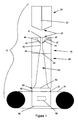
- Apparatus 10 for spinning and collecting relatively straight fibers in a relatively unentangled two dimensional format.
- Apparatus 10 includes a blow spinning die head 20, a venturi 40, a diffusion chamber 60 and a laydown surface 65.
- the apparatus of the present invention includes an exhaust chamber 80 and a means for moving gas (not shown).
- the means for moving gas may be a vacuum pump, a blower or other suitable apparatus.
- the spinning of fibers requires heating a spinnable material to a temperature sufficient to allow the substance to pass through a capillary.
- the means for heating the spinnable substance may be located externally of the blow spinning die or internally.
- further details on this aspect are not necessary. Rather, greater detail is provided in U.S. Patent Nos. 3,755,527; 4,526,733; 4,818,463 and the article "Superfine Thermoplastic Fibers" by Van A. Wente, Industrial Engineering Chemistry, Vol. 48, page 1342 (1956).
- venturi 40 Positioned downstream of die head 20 is a venturi 40.
- venturi 40 will have a length of about 35 cm (14 inches) or less.
- venturi 40 and die head 20 may be a single unit or may comprise two units in direct contact.
- a distance, defined as opening 27, will exist between die head 20 and venturi 40.
- Factors in determining the distance of opening 27 are the thermosetting characteristics of the spun fiber and the cooling effect of the second flowing gas stream.
- opening 27 will be a distance of from about 0.635 - 254 cm (25 inches to about 100 inches).
- the distance will generally be between about 5.08 - 10.16 cm (2 to 4 inches). However, the distance may be even greater than 254 cm (100 inches) for other fiber feedstocks.
- the preparation of solvated mesophase pitch is described in U.S. Patent Nos. 5,259,947 and 5,437,780.
- thermosetting zone For carbon fibers spun from solvated mesophase pitch, the region between the die head and the venturi will typically correspond to the thermosetting zone of the fiber. However, for certain fibers, the thermosetting zone may extend into the venturi. As previously noted, the thermosetting zone is that region in space in which the fiber becomes thermoset.
- Venturi 40 has a passage 42 extending through its length. Passage 42 has a first open end 41 and a second open end 43. Passage 42 is positioned downstream of capillary 22 in order to receive the spun fibers. Venturi 40 may contain two or more gas jets 44 and 45 for directing a gas stream onto the spun fibers as they pass through passage 42. Gas jets 44 and 45 may be flush with the walls of passage 42 or may extend into passage 42. Gas jets 44 and 45 are in fluid communication with a manifold 46 located within the venturi 40. Manifold 46 receives a supply of pressurized gas by means of passage 47 from an external source, not depicted.
- apparatus 10 is located within a sealed chamber (not shown) which contains a non-reactive atmosphere.
- the preferred atmosphere is an inert gas such as nitrogen.
- pressurized nitrogen gas is passed into venturi 40 through open end 41. The gas passes with the spun fibers into venturi 40 and provides a second flowing gas stream to physically stabilize the fibers until they are substantially thermoset. In this manner, the second flowing gas stream passing with the fiber through venturi 40 tensions the fiber and reduces or neutralizes the effect of turbulence on the fiber which would otherwise lead to bent and kinked fibers. Further, this preferred embodiment eliminates the need for gas jets 44 and 45, manifold 46 and passage 47 within venturi 40 as shown in Fig. 2.
- Diffusion chamber 60 receives the thermoset fiber as it exits from passage 42 and provides a means for dissipating the gas stream.
- diffusion chamber 60 has an internal passage 62 which gradually increases in area as it progresses from a first open end 63 adjacent to passage 42 to a second open end 64. This gradual increase in area about the fiber as it passes through diffusion chamber 60, provides a means for dissipating the velocity and kinetic energy of the gas stream. This gradual dissipation of the energy of the second flowing gas stream minimizes and preferably precludes the development of turbulence about the fiber.
- a diffusion chamber having a constant internal area but which gradually opens up to the atmosphere.
- these alternative embodiment might include a screened or perforated chamber.
- the present invention includes the construction of the venturi and the diffusion chamber as a single integral unit. Additionally, certain processing conditions may necessitate the heating of the walls of diffusion chamber 60 in order to preclude the condensation of monomer and/or spinning or solvating solvent thereon.
- laydown surface 65 Positioned beneath diffusion chamber 60 is a laydown surface 65.
- Laydown surface 65 preferably will allow the gas stream to pass freely through its surface.
- Laydown surface 65 may be in the form of a foraminous screen, plate or a belt.
- a laydown surface 65 in the form of a conveyor belt may be desirable for its ability to transport fibers away from apparatus 10 allowing for continuous production of fibers.
- Apparatus 10 may optionally include an exhaust conduit 80.
- laydown surface 65 may be located within or pass through conduit 80 as shown in the drawing.
- Exhaust conduit 80 has an opening 83 that surrounds end 64 of diffusion chamber 60. Positioned beneath end 64 is the laydown surface 65. Opening 83 allows the fibers to pass from diffusion chamber 60 onto laydown surface 65.
- Exhaust conduit 80 also has an opening 86 to allow for the venting of gases to the atmosphere. Optionally, these gases may be recycled to either gas source, repressurized and used in either the spinning head 20 or venturi 40.
- exhaust conduit 80 may be provided with rolling seals 82 or other means to allow for passage of the belt and fibers out of exhaust conduit 80 without disrupting the flow of gas through conduit 80.
- Apparatus 10 may optionally include an gas moving means (not shown).
- the gas moving means will have a negative pressure opening and a positive pressure opening.
- the gas moving means is a vacuum pump or a blower and it is used in conjunction with exhaust conduit 80 with the negative pressure opening being connected to exhaust conduit opening 86. In this configuration a vacuum pump will pull additional gas down through the fibers as they are collected on laydown surface 65. The passage of gas through the fibers enhances the collection of the fibers in a two dimensional format.
- the positive pressure opening of the gas moving means may be connected to the gas source of the blow spinning die allowing for the recycling of the gas used in the spinning process.
- the present invention provides a process for laying down and collecting relatively straight unentangled blow spun fibers.
- the present invention is particularly useful for producing carbon fibers from solvated pitch, including solvated mesophase pitch.
- solvated pitch including solvated mesophase pitch.
- the following discussion will center on the collection of fibers spun from a solvated mesophase pitch; however, one skilled in the art will recognize that the present invention will have application in all areas of blow spinning.
- the process of the present invention is initiated by heating a spinnable substance such as solvated mesophase pitch to a temperature sufficient to allow it to pass through a capillary in a blow spinning die.
- a spinnable substance such as solvated mesophase pitch
- the methods of heating and passing a spinnable substance through a capillary are well known in the art and will not be repeated herein.
- the gas is directed onto the fiber by at least two gas passages.
- annular dies the gas passes through a single passage which surrounds the capillary. In either case the flowing gas attenuates the fiber after it exits the capillary. As the fiber is attenuated it becomes thinner and longer.
- the blow spinning of carbonaceous pitch typically yielded bent and kinked carbon fibers.
- This kinking and bending of the fibers is attributed to the turbulence generated by the flowing gas stream. Because the fibers are kinked and bent prior to and during thermosetting, the resulting finished fibers are also kinked and bent. These fibers are extremely difficult to collect and usually accumulate in a low apparent density entangled three dimensional mass.
- the process of the present invention advantageously provides for the collection of relatively straight fibers in a substantially non-entangled two dimensional format.
- the fibers once the fibers exit the blow spinning die, they pass through a thermosetting. zone, as previously defined, and into a venturi. Passing with the fibers into the venturi is a second flowing stream of gas.
- the second flowing stream of gas has a velocity greater than that of the fibers and places the fibers under tension during the thermosetting process.
- the second flowing gas stream maintains the fibers in a relatively straight configuration as they thermoset.
- the thermosetting process may occur prior to the fibers entering the venturi.
- the fibers thermoset regardless of the zone in which the fibers thermoset, they will remain relatively free of bends and kinks due to the tension placed on the fibers by the second flowing stream of gas.
- the second flowing stream of gas maintains tension on the fibers during the thermosetting process.
- the gas does not chemically alter the fibers; however, some solvent may be removed from the fiber by passage of the gas.
- the fibers become substantially thermoset while remaining substantially free of kinks and bends.
- the venturi may internally provide a second flowing stream of gas directed at the fibers.
- the second flowing stream of gas operates in the manner described above to place tension on the fibers and maintain them in a relatively straight configuration until the fiber substantially thermosets.
- the second flowing gas stream within the venturi may further attenuate or draw the fiber.
- the process In order to provide a cost effective fiber, the process must also preclude the entangling of the fiber as it accumulates on a collection surface.
- the present invention passes the fiber through a diffusion chamber or region. As previously discussed, the diffusion chamber dissipates the kinetic energy of the second flowing gas stream.
- the process allows the fibers to fall in an unentangled manner onto the laydown surface where they may be collected in a relatively flat two dimensional manner.
- the laydown surface is sufficiently porous to allow for passage of the gas through the fibers.
- the process of the present invention further provides for the use of an exhaust conduit in conjunction with a vacuum pump or blower.
- fibers passing out of the diffusion chamber are collected on a porous laydown surface located within the exhaust conduit.
- the laydown surface will be a conveyor belt which transports the fibers out of the exhaust conduit through a rolling seal or vacuum box.
- the vacuum pump normally will be connected to the exhaust conduit in a manner to allow for the generation of a vacuum within the exhaust conduit. In this manner, the vacuum pump will pull additional gas down through the fibers as they are collected on the laydown surface. Thus, the vacuum pump enhances the collection of the fibers in a two dimensional format.
- the vacuum pump in cooperation with the venturi may preclude the generation of turbulence about the fiber without the need for a second flowing gas stream generated within the venturi.
- the vacuum pump pulls sufficient gas or air through the opening between the spinning head and the venturi to preclude the generation of turbulence about the fiber by using negative pressure, rather than positive pressure to generate the second flowing stream of gas which contacts the fiber.
- the second flowing stream of gas passes into the venturi along with the fiber and maintains the fiber in relatively straight configuration until the fiber thermosets.
- use of the vacuum pump may allow for the recycling of the gas to any part of the system.
Landscapes
- Engineering & Computer Science (AREA)
- Textile Engineering (AREA)
- Chemical & Material Sciences (AREA)
- Chemical Kinetics & Catalysis (AREA)
- General Chemical & Material Sciences (AREA)
- Mechanical Engineering (AREA)
- Spinning Methods And Devices For Manufacturing Artificial Fibers (AREA)
- Inorganic Fibers (AREA)
- Sampling And Sample Adjustment (AREA)
- Artificial Filaments (AREA)
- Yarns And Mechanical Finishing Of Yarns Or Ropes (AREA)
Description
Claims (17)
- A process for preparing relatively straight blow spun fibers comprising:blow spinning a fiber using at least one flowing stream of gas;contacting said fiber with at least one additional flowing stream of gas to place said fiber under tension;thermosetting said fiber while under tension, characterised in that the velocity of said additional flowing stream of gas is greater than the velocity of said fiber.
- The process of claim 1, having the additional steps of:dissipating said at least one additional flowing stream of gas by passing said gas and said fiber into a diffusion chamber (60);passing said fiber out of said diffusion chamber (60); andcollecting said fiber.
- The process of claims 1 or 2, including the step of passing said fiber and said additional flowing stream of gas into a venturi (40).
- The process of claim 1, 2 or 3, wherein the step of blow spinning comprises
heating a spinnable substance to a temperature sufficient to allow said substance to flow followed by forming a fiber by passing said substance into a spinning die (20) and through a capillary (22) located within said die (20);
attenuating said fiber as it exits the capillary (22) by contacting said fiber with at least one stream of gas. - The process of claim 4, wherein said fiber exits said capillary (22) and passes a distance from said die (20) prior to being contacted with said at least one additional flowing stream of gas.
- The process of any preceding claim, wherein said fiber is spun from a carbonaceous pitch.
- The process of any of claims 1 to 5 wherein said fiber is spun from a solvated mesophase pitch.
- An apparatus (10) for blow spinning fibers comprising:characterised in that the distance between said venturi (40) and said blow spinning die head (20) ranges from 0.635 - 254 cm (0.25 inches to 100 inches); and further comprising means for passing a second gas stream into said first open end (41) of said passage (42) through said venturi (40); said second gas stream having a velocity greater than the velocity of said fiber.a blow spinning die head (20) containing at least one capillary (22) having a first opening for receiving a spinnable substance and a second opening (27) for passing said substance out of said capillary (22) as a fiber and a means for directing at least one gas stream onto the exiting fiber;a venturi (40) positioned downstream of said blow spinning die head (20), said venturi containing a passage (42) therethrough, said passage (42) having first (41) and second (43) open ends, said first open end (41) positioned to receive a fiber as it exits said blow spinning die (20);
- The apparatus of claim 8, wherein said distance between said venturi (40) and said blow spinning die head (20) ranges from 2 to about 12 inches (5.08 - 30.48 cm).
- The apparatus of claims 8 or 9, wherein said distance between said venturi (40) and said blow spinning die head (20) ranges from 2 to 4 inches (5.08 - 10.16 cm).
- The apparatus of claims 8, 9 or 10, wherein said distance between said venturi (40) and said blow spinning die head (20) is less than that distance at which said flowing gas stream begins to develop turbulence about said fiber.
- The apparatus of any of claims 8 to 11, additionally comprising:a diffusion chamber (60) located downstream of said venturi (40);said diffusion chamber (60) having a first open end (63) positioned downstream of said second open end (43) of said passage (42) through said venturi (40) and a second open end (64) to allow said fiber to exit said diffusion chamber (60).
- The apparatus of claim 12, wherein said diffusion chamber (60) has an internal diameter which progressively increases from a minimum diameter at the first open end (41) to a maximum diameter at the second open end (43).
- The apparatus of claims 12 or 13, additionally comprising a laydown surface (65) located beneath said second open end (64) of said diffusion chamber (60).
- The apparatus of claims 12, 13 or 14 wherein said apparatus (10) is located within a sealed chamber.
- The apparatus of claim 15, wherein said sealed chamber contains a non-reactive atmosphere.
- The apparatus of any of claims 12 to 16, wherein said venturi (40) and said diffusion chamber (60) are a single apparatus.
Applications Claiming Priority (3)
| Application Number | Priority Date | Filing Date | Title |
|---|---|---|---|
| US436030 | 1982-10-22 | ||
| US08/436,030 US5648041A (en) | 1995-05-05 | 1995-05-05 | Process and apparatus for collecting fibers blow spun from solvated mesophase pitch |
| PCT/US1996/003253 WO1996035009A1 (en) | 1995-05-05 | 1996-03-08 | Process of and apparatus for collecting fibers |
Publications (3)
| Publication Number | Publication Date |
|---|---|
| EP0840812A1 EP0840812A1 (en) | 1998-05-13 |
| EP0840812A4 EP0840812A4 (en) | 1999-02-03 |
| EP0840812B1 true EP0840812B1 (en) | 2002-06-19 |
Family
ID=23730815
Family Applications (1)
| Application Number | Title | Priority Date | Filing Date |
|---|---|---|---|
| EP96908742A Expired - Lifetime EP0840812B1 (en) | 1995-05-05 | 1996-03-08 | Process of and apparatus for collecting fibers |
Country Status (15)
| Country | Link |
|---|---|
| US (1) | US5648041A (en) |
| EP (1) | EP0840812B1 (en) |
| JP (1) | JPH11504400A (en) |
| CN (1) | CN1066213C (en) |
| CA (1) | CA2214282A1 (en) |
| DE (1) | DE69621934T2 (en) |
| ES (1) | ES2175082T3 (en) |
| IN (1) | IN189412B (en) |
| MX (1) | MX9708206A (en) |
| NO (1) | NO312974B1 (en) |
| SG (1) | SG79204A1 (en) |
| TW (1) | TW412605B (en) |
| UA (1) | UA49828C2 (en) |
| WO (1) | WO1996035009A1 (en) |
| ZA (1) | ZA962480B (en) |
Families Citing this family (25)
| Publication number | Priority date | Publication date | Assignee | Title |
|---|---|---|---|---|
| US5863565A (en) * | 1996-05-15 | 1999-01-26 | Conoco Inc. | Apparatus for forming a single layer batt from multiple curtains of fibers |
| BR9814678A (en) * | 1997-11-20 | 2000-10-03 | Conoco Inc | Process and apparatus for continuous collection twisted by blowing |
| JP3658284B2 (en) * | 2000-07-05 | 2005-06-08 | ユニ・チャーム株式会社 | Nonwoven fabric manufacturing equipment |
| FR2815647B1 (en) * | 2000-10-20 | 2003-02-14 | Rieter Perfojet | INSTALLATION FOR PRODUCING A NONWOVEN FABRIC WITH A DIFFUSER AND FOR SEPARATING FILAMENTS ELECTROSTATICALLY |
| EP1337703B1 (en) * | 2000-11-20 | 2009-01-14 | 3M Innovative Properties Company | Fiber-forming process |
| US20030003834A1 (en) * | 2000-11-20 | 2003-01-02 | 3M Innovative Properties Company | Method for forming spread nonwoven webs |
| US6607624B2 (en) | 2000-11-20 | 2003-08-19 | 3M Innovative Properties Company | Fiber-forming process |
| ATE377107T1 (en) * | 2001-09-26 | 2007-11-15 | Bba Nonwovens Simpsonville Inc | METHOD AND DEVICE FOR PRODUCING A NON-WOVEN WEB FROM FILAMENTS |
| US6846450B2 (en) * | 2002-06-20 | 2005-01-25 | 3M Innovative Properties Company | Method for making a nonwoven web |
| US7537824B2 (en) * | 2002-10-24 | 2009-05-26 | Borgwarner, Inc. | Wet friction material with pitch carbon fiber |
| WO2005012619A1 (en) * | 2003-07-25 | 2005-02-10 | University Of Tennessee Research Foundation | Process and apparatus for collection of continuous fibers as a uniform batt |
| US8021744B2 (en) | 2004-06-18 | 2011-09-20 | Borgwarner Inc. | Fully fibrous structure friction material |
| US7429418B2 (en) | 2004-07-26 | 2008-09-30 | Borgwarner, Inc. | Porous friction material comprising nanoparticles of friction modifying material |
| US8603614B2 (en) | 2004-07-26 | 2013-12-10 | Borgwarner Inc. | Porous friction material with nanoparticles of friction modifying material |
| US7806975B2 (en) | 2005-04-26 | 2010-10-05 | Borgwarner Inc. | Friction material |
| EP1943300B1 (en) | 2005-11-02 | 2016-07-06 | BorgWarner, Inc. | Carbon friction materials |
| US8246898B2 (en) * | 2007-03-19 | 2012-08-21 | Conrad John H | Method and apparatus for enhanced fiber bundle dispersion with a divergent fiber draw unit |
| ES2440244T3 (en) * | 2007-06-29 | 2014-01-28 | Reifenhäuser GmbH & Co. KG Maschinenfabrik | Device for manufacturing nonwoven fabric |
| DE102008013907B4 (en) | 2008-03-12 | 2016-03-10 | Borgwarner Inc. | Frictionally-locking device with at least one friction plate |
| DE102009030506A1 (en) | 2008-06-30 | 2009-12-31 | Borgwarner Inc., Auburn Hills | friction materials |
| IT1394153B1 (en) * | 2008-10-21 | 2012-05-25 | Fein Elast Italia S P A | PLANT AND PROCEDURE FOR THE REALIZATION OF CONTINUOUS EXTRUDES IN CONTINUOUS SILICON AND EXTRUDED MATERIALS IN SILICONE MATERIAL SO AS OBTAINED |
| EP2603626B9 (en) * | 2010-08-12 | 2015-11-04 | Boma Engineering Srl | Process and apparatus for spinning fibres and in particular for producing a fibrous-containing nonwoven |
| CN103935838A (en) * | 2014-03-27 | 2014-07-23 | 吴江明佳织造有限公司 | Venturi tube doubling machine |
| CN110042483B (en) * | 2019-04-29 | 2021-05-04 | 湖南东映碳材料科技有限公司 | Method for recovering broken ends in continuous spinning process of mesophase pitch |
| CN110629299A (en) * | 2019-09-29 | 2019-12-31 | 天津工业大学 | Continuous preparation device and continuous preparation method of nanofiber yarns |
Family Cites Families (15)
| Publication number | Priority date | Publication date | Assignee | Title |
|---|---|---|---|---|
| US3755527A (en) * | 1969-10-09 | 1973-08-28 | Exxon Research Engineering Co | Process for producing melt blown nonwoven synthetic polymer mat having high tear resistance |
| US4402900A (en) * | 1982-11-01 | 1983-09-06 | E. I. Du Pont De Nemours & Co. | Dry spinning process with a gas flow amplifier |
| US4526733A (en) * | 1982-11-17 | 1985-07-02 | Kimberly-Clark Corporation | Meltblown die and method |
| DE3401639A1 (en) * | 1984-01-19 | 1985-07-25 | Hoechst Ag, 6230 Frankfurt | DEVICE FOR PRODUCING A SPINNING FLEECE |
| US4818463A (en) * | 1986-04-26 | 1989-04-04 | Buehning Peter G | Process for preparing non-woven webs |
| US5141700A (en) * | 1986-04-30 | 1992-08-25 | E. I. Du Pont De Nemours And Company | Melt spinning process for polyamide industrial filaments |
| US4687610A (en) * | 1986-04-30 | 1987-08-18 | E. I. Du Pont De Neumours And Company | Low crystallinity polyester yarn produced at ultra high spinning speeds |
| JPS6385116A (en) * | 1986-09-26 | 1988-04-15 | Dainippon Ink & Chem Inc | Heat insulating material of carbon fiber |
| DE3701531A1 (en) * | 1987-01-21 | 1988-08-04 | Reifenhaeuser Masch | METHOD AND SYSTEM FOR PRODUCING A SPINNED FLEECE |
| DE3713862A1 (en) * | 1987-04-25 | 1988-11-10 | Reifenhaeuser Masch | METHOD AND SPINNED FLEECE SYSTEM FOR PRODUCING A SPINNED FLEECE FROM SYNTHETIC CONTINUOUS FILAMENT |
| US5141699A (en) * | 1987-12-21 | 1992-08-25 | Minnesota Mining And Manufacturing Company | Process for making oriented melt-blown microfibers |
| US5145689A (en) * | 1990-10-17 | 1992-09-08 | Exxon Chemical Patents Inc. | Meltblowing die |
| US5259947A (en) * | 1990-12-21 | 1993-11-09 | Conoco Inc. | Solvated mesophase pitches |
| US5236641A (en) * | 1991-09-11 | 1993-08-17 | Exxon Chemical Patents Inc. | Metering meltblowing system |
| DE4332345C2 (en) * | 1993-09-23 | 1995-09-14 | Reifenhaeuser Masch | Process and fleece blowing system for the production of a spunbonded web with high filament speed |
-
1995
- 1995-05-05 US US08/436,030 patent/US5648041A/en not_active Expired - Fee Related
-
1996
- 1996-03-08 MX MX9708206A patent/MX9708206A/en unknown
- 1996-03-08 CN CN96193741A patent/CN1066213C/en not_active Expired - Fee Related
- 1996-03-08 EP EP96908742A patent/EP0840812B1/en not_active Expired - Lifetime
- 1996-03-08 DE DE69621934T patent/DE69621934T2/en not_active Expired - Fee Related
- 1996-03-08 UA UA97115379A patent/UA49828C2/en unknown
- 1996-03-08 JP JP8533288A patent/JPH11504400A/en not_active Withdrawn
- 1996-03-08 CA CA002214282A patent/CA2214282A1/en not_active Abandoned
- 1996-03-08 WO PCT/US1996/003253 patent/WO1996035009A1/en active IP Right Grant
- 1996-03-08 ES ES96908742T patent/ES2175082T3/en not_active Expired - Lifetime
- 1996-03-15 IN IN471CA1996 patent/IN189412B/en unknown
- 1996-03-28 ZA ZA9602480A patent/ZA962480B/en unknown
- 1996-04-01 TW TW085103812A patent/TW412605B/en not_active IP Right Cessation
- 1996-10-23 SG SG9610944A patent/SG79204A1/en unknown
-
1997
- 1997-11-04 NO NO19975077A patent/NO312974B1/en not_active IP Right Cessation
Also Published As
| Publication number | Publication date |
|---|---|
| TW412605B (en) | 2000-11-21 |
| CN1183815A (en) | 1998-06-03 |
| ZA962480B (en) | 1997-09-29 |
| IN189412B (en) | 2003-02-22 |
| MX9708206A (en) | 1997-12-31 |
| CA2214282A1 (en) | 1996-11-07 |
| NO975077L (en) | 1997-11-04 |
| WO1996035009A1 (en) | 1996-11-07 |
| ES2175082T3 (en) | 2002-11-16 |
| EP0840812A4 (en) | 1999-02-03 |
| DE69621934D1 (en) | 2002-07-25 |
| DE69621934T2 (en) | 2002-12-19 |
| UA49828C2 (en) | 2002-10-15 |
| US5648041A (en) | 1997-07-15 |
| NO975077D0 (en) | 1997-11-04 |
| EP0840812A1 (en) | 1998-05-13 |
| JPH11504400A (en) | 1999-04-20 |
| CN1066213C (en) | 2001-05-23 |
| SG79204A1 (en) | 2001-03-20 |
| NO312974B1 (en) | 2002-07-22 |
Similar Documents
| Publication | Publication Date | Title |
|---|---|---|
| EP0840812B1 (en) | Process of and apparatus for collecting fibers | |
| US6572798B2 (en) | Apparatus and method for spinning a multifilament yarn | |
| CA2274771A1 (en) | Nonwoven process and apparatus | |
| KR940018507A (en) | How to Make Sorption Articles | |
| CA2147690C (en) | Stationary-pressure apparatus for producing spun-bond web | |
| US5863565A (en) | Apparatus for forming a single layer batt from multiple curtains of fibers | |
| EP1629141B1 (en) | Apparatus and method for controlling airflow in a fiber extrusion system | |
| AU720637B2 (en) | Process and apparatus for collecting fibers blow spun from solvated mesophase pitch | |
| US5112562A (en) | Method and apparatus for manufacturing nonwoven fabrics | |
| JP4334342B2 (en) | Filament drawing jet apparatus and method | |
| US6558610B1 (en) | Process and apparatus for collecting continuous blow spun fibers | |
| EP3438339A1 (en) | Non-woven fabric manufacturing device, non-woven fabric manufacturing method, and non-woven fabric | |
| US8206640B2 (en) | Process for collection of continuous fibers as a uniform batt | |
| JPS59130323A (en) | Method and apparatus for spinning yarn from staple fiber in whirled air | |
| RU2171867C2 (en) | Method and apparatus for collecting fibers drawn by gas flow from carbonaceous resin | |
| JP3163821B2 (en) | Fiber web production equipment | |
| KR100429700B1 (en) | Method and apparatus for focusing blown spun fibers in sonicated intermediate pitch | |
| JPS60151356A (en) | Apparatus for producing fiber web | |
| JP3259568B2 (en) | Synthetic fiber melt spinning method | |
| JPH03500908A (en) | Melt spinning equipment with high winding speed and filament produced by the equipment | |
| JP2790357B2 (en) | Air gun for nonwoven fabric production | |
| MXPA00004637A (en) | Process and apparatus for collecting continuous blow spun fibers | |
| JPS60215807A (en) | Filament collecting |
Legal Events
| Date | Code | Title | Description |
|---|---|---|---|
| PUAI | Public reference made under article 153(3) epc to a published international application that has entered the european phase |
Free format text: ORIGINAL CODE: 0009012 |
|
| 17P | Request for examination filed |
Effective date: 19971127 |
|
| AK | Designated contracting states |
Kind code of ref document: A1 Designated state(s): DE ES FR GB IT NL SE |
|
| A4 | Supplementary search report drawn up and despatched |
Effective date: 19981222 |
|
| AK | Designated contracting states |
Kind code of ref document: A4 Designated state(s): DE ES FR GB IT NL SE |
|
| 17Q | First examination report despatched |
Effective date: 20001121 |
|
| GRAG | Despatch of communication of intention to grant |
Free format text: ORIGINAL CODE: EPIDOS AGRA |
|
| GRAG | Despatch of communication of intention to grant |
Free format text: ORIGINAL CODE: EPIDOS AGRA |
|
| GRAH | Despatch of communication of intention to grant a patent |
Free format text: ORIGINAL CODE: EPIDOS IGRA |
|
| GRAH | Despatch of communication of intention to grant a patent |
Free format text: ORIGINAL CODE: EPIDOS IGRA |
|
| GRAA | (expected) grant |
Free format text: ORIGINAL CODE: 0009210 |
|
| AK | Designated contracting states |
Kind code of ref document: B1 Designated state(s): DE ES FR GB IT NL SE |
|
| REG | Reference to a national code |
Ref country code: GB Ref legal event code: FG4D |
|
| REF | Corresponds to: |
Ref document number: 69621934 Country of ref document: DE Date of ref document: 20020725 |
|
| ET | Fr: translation filed | ||
| REG | Reference to a national code |
Ref country code: ES Ref legal event code: FG2A Ref document number: 2175082 Country of ref document: ES Kind code of ref document: T3 |
|
| PLBE | No opposition filed within time limit |
Free format text: ORIGINAL CODE: 0009261 |
|
| STAA | Information on the status of an ep patent application or granted ep patent |
Free format text: STATUS: NO OPPOSITION FILED WITHIN TIME LIMIT |
|
| 26N | No opposition filed |
Effective date: 20030320 |
|
| REG | Reference to a national code |
Ref country code: GB Ref legal event code: 732E |
|
| PGFP | Annual fee paid to national office [announced via postgrant information from national office to epo] |
Ref country code: GB Payment date: 20040205 Year of fee payment: 9 |
|
| PGFP | Annual fee paid to national office [announced via postgrant information from national office to epo] |
Ref country code: NL Payment date: 20040209 Year of fee payment: 9 |
|
| PGFP | Annual fee paid to national office [announced via postgrant information from national office to epo] |
Ref country code: FR Payment date: 20040302 Year of fee payment: 9 |
|
| PGFP | Annual fee paid to national office [announced via postgrant information from national office to epo] |
Ref country code: SE Payment date: 20040303 Year of fee payment: 9 |
|
| PGFP | Annual fee paid to national office [announced via postgrant information from national office to epo] |
Ref country code: ES Payment date: 20040322 Year of fee payment: 9 |
|
| PGFP | Annual fee paid to national office [announced via postgrant information from national office to epo] |
Ref country code: DE Payment date: 20040331 Year of fee payment: 9 |
|
| NLS | Nl: assignments of ep-patents |
Owner name: CONOCOPHILLIPS COMPANY |
|
| REG | Reference to a national code |
Ref country code: FR Ref legal event code: TP |
|
| PG25 | Lapsed in a contracting state [announced via postgrant information from national office to epo] |
Ref country code: GB Free format text: LAPSE BECAUSE OF NON-PAYMENT OF DUE FEES Effective date: 20050308 Ref country code: IT Free format text: LAPSE BECAUSE OF NON-PAYMENT OF DUE FEES Effective date: 20050308 |
|
| PG25 | Lapsed in a contracting state [announced via postgrant information from national office to epo] |
Ref country code: SE Free format text: LAPSE BECAUSE OF NON-PAYMENT OF DUE FEES Effective date: 20050309 Ref country code: ES Free format text: LAPSE BECAUSE OF NON-PAYMENT OF DUE FEES Effective date: 20050309 |
|
| PG25 | Lapsed in a contracting state [announced via postgrant information from national office to epo] |
Ref country code: NL Free format text: LAPSE BECAUSE OF NON-PAYMENT OF DUE FEES Effective date: 20051001 Ref country code: DE Free format text: LAPSE BECAUSE OF NON-PAYMENT OF DUE FEES Effective date: 20051001 |
|
| EUG | Se: european patent has lapsed | ||
| GBPC | Gb: european patent ceased through non-payment of renewal fee |
Effective date: 20050308 |
|
| PG25 | Lapsed in a contracting state [announced via postgrant information from national office to epo] |
Ref country code: FR Free format text: LAPSE BECAUSE OF NON-PAYMENT OF DUE FEES Effective date: 20051130 |
|
| NLV4 | Nl: lapsed or anulled due to non-payment of the annual fee |
Effective date: 20051001 |
|
| REG | Reference to a national code |
Ref country code: FR Ref legal event code: ST Effective date: 20051130 |
|
| REG | Reference to a national code |
Ref country code: ES Ref legal event code: FD2A Effective date: 20050309 |