EP0840579B1 - A buttress for cardiac valve reconstruction - Google Patents
A buttress for cardiac valve reconstruction Download PDFInfo
- Publication number
- EP0840579B1 EP0840579B1 EP96925951A EP96925951A EP0840579B1 EP 0840579 B1 EP0840579 B1 EP 0840579B1 EP 96925951 A EP96925951 A EP 96925951A EP 96925951 A EP96925951 A EP 96925951A EP 0840579 B1 EP0840579 B1 EP 0840579B1
- Authority
- EP
- European Patent Office
- Prior art keywords
- buttress
- fabric
- elongate member
- receiving area
- rim
- Prior art date
- Legal status (The legal status is an assumption and is not a legal conclusion. Google has not performed a legal analysis and makes no representation as to the accuracy of the status listed.)
- Expired - Lifetime
Links
Images


Classifications
-
- A—HUMAN NECESSITIES
- A61—MEDICAL OR VETERINARY SCIENCE; HYGIENE
- A61F—FILTERS IMPLANTABLE INTO BLOOD VESSELS; PROSTHESES; DEVICES PROVIDING PATENCY TO, OR PREVENTING COLLAPSING OF, TUBULAR STRUCTURES OF THE BODY, e.g. STENTS; ORTHOPAEDIC, NURSING OR CONTRACEPTIVE DEVICES; FOMENTATION; TREATMENT OR PROTECTION OF EYES OR EARS; BANDAGES, DRESSINGS OR ABSORBENT PADS; FIRST-AID KITS
- A61F2/00—Filters implantable into blood vessels; Prostheses, i.e. artificial substitutes or replacements for parts of the body; Appliances for connecting them with the body; Devices providing patency to, or preventing collapsing of, tubular structures of the body, e.g. stents
- A61F2/02—Prostheses implantable into the body
- A61F2/24—Heart valves ; Vascular valves, e.g. venous valves; Heart implants, e.g. passive devices for improving the function of the native valve or the heart muscle; Transmyocardial revascularisation [TMR] devices; Valves implantable in the body
- A61F2/2442—Annuloplasty rings or inserts for correcting the valve shape; Implants for improving the function of a native heart valve
- A61F2/2445—Annuloplasty rings in direct contact with the valve annulus
-
- A—HUMAN NECESSITIES
- A61—MEDICAL OR VETERINARY SCIENCE; HYGIENE
- A61F—FILTERS IMPLANTABLE INTO BLOOD VESSELS; PROSTHESES; DEVICES PROVIDING PATENCY TO, OR PREVENTING COLLAPSING OF, TUBULAR STRUCTURES OF THE BODY, e.g. STENTS; ORTHOPAEDIC, NURSING OR CONTRACEPTIVE DEVICES; FOMENTATION; TREATMENT OR PROTECTION OF EYES OR EARS; BANDAGES, DRESSINGS OR ABSORBENT PADS; FIRST-AID KITS
- A61F2/00—Filters implantable into blood vessels; Prostheses, i.e. artificial substitutes or replacements for parts of the body; Appliances for connecting them with the body; Devices providing patency to, or preventing collapsing of, tubular structures of the body, e.g. stents
- A61F2/02—Prostheses implantable into the body
- A61F2/24—Heart valves ; Vascular valves, e.g. venous valves; Heart implants, e.g. passive devices for improving the function of the native valve or the heart muscle; Transmyocardial revascularisation [TMR] devices; Valves implantable in the body
- A61F2/2442—Annuloplasty rings or inserts for correcting the valve shape; Implants for improving the function of a native heart valve
- A61F2/2466—Delivery devices therefor
Definitions
- the present invention relates to a buttress for cardiac valve reconstruction of atrioventricular cardiac valves.
- the mitral and tricuspid valves are located in the left and right atrioventricular openings, respectively, of the heart and serve to prevent regurgitation of blood from the ventricle into the atrium when the ventricle contracts during systole.
- the mitral valve which is surrounded by a dense fibrous ring known as the annulus, comprises two valve cusps or leaflets of unequal size, the large or anterior leaflet adjacent the aortic opening and the smaller posterior leaflet.
- the line at which the leaflets come together is called the commissure.
- the tricuspid valve comprises three leaflets, usually referred to as the anterior, posterior and septal cusps, which are attached to a fibrous ring known as the annulus.
- the mitral valve is subjected to significantly higher back pressure than the tricuspid valve. Accordingly, it is more common to require surgery to repair a mitral valve than a tricuspid valve and, therefore, the discussion herein is primarily concerned with mitral valve reconstruction. However, it will be understood that the same principles apply in respect of both mitral and tricuspid valve reconstruction.
- each annulus In a normal heart, the mitral and tricuspid annuli move in a dynamic and non-planar way with each cardiac cycle.
- the circumference of the mitral and tricuspid annuli reduce during systole, so that their respective surface areas reduce by about 20-25%, and then enlarge correspondingly during diastole.
- the movement of each annulus, which is non-planar, is difficult to describe but would be similar to a pitching, yawing, rolling or rotation motion. All the components of each annulus do not necessarily move to the same degree.
- annuloplasty buttress comprises a rigid annular or part-annular member which is dimensioned to fit against the base of the valve leaflets and is secured in place by sutures.
- Known rigid annular (or closed) annuloplasty rings affect the movement of the annulus by preventing normal movement, specifically, by restricting it to planar movement. This reduces ventricular function and, if the ventricle is compromised already, is likely to reduce its efficiency further.
- Another disadvantage of such non-planar movement is a tendancy to force the rigid ring to dehisce or be torn loose from the annulus by the securing sutures being pulled through the tissue. This happens as a result of the stress caused by restraining the annulus from undergoing normal physiological changes during each cardiac cycle.
- the closed nature of a rigid ring prevents the natural change in the circumference of the annulus, in particular, that which occurs during diastole (the relaxation phase of the cardiac cycle) when the surface area of the mitral and tricuspid valve orifices increase by 20-25%.
- the rigid closed ring limits the movement of the anterior mitral leaflet in the inter-trigonal region. This effectively limits the ability of the closed ring system and, at high flow rates across the mitral or tricuspid valve, is likely to produce obstruction/stenosis.
- a flexible closed ring was devised for use in atrioventricular annuloplasty.
- the structural properties of the material required for the flexible closed ring are inertness and non-biodegradability.
- the material should also permit good, but not excessive, tissue in-growth since excessive tissue in-growth would convert the flexible nature of the device into a rigid device. It was expected that a flexible ring would permit normal movement of the annulus during the cardiac cycle. This should allow the heart to function in a more natural manner and, in addition, should decrease the tendancy of dehiscence because the stress forces in any particular part of the ring would be reduced.
- a subsequent modification of the flexible closed ring involved the incorporation of a traction thread which passes through the interior of the ring, with both ends exiting the ring a short distance apart.
- a ring once implanted, can be reduced in circumferential size, by pulling on the traction thread to contract the ring either symmetrically, by pulling both ends of the traction thread the same amount, or asymmetrically, by pulling one end more than the other. Once the desired ring circumferential size has been achieved, the ends of the traction thread are then tied off.
- a flexible closed ring has less device-related problems such as haemolysis (red cell damage), or shear damage across the device than a rigid ring. Furthermore, the flexible nature of the flexible closed ring interferes less with ventricular function than the rigid systems described above.
- each of such known closed flexible rings fail to restore normal heart valve function since, as mentioned above, the most common mitral heart valve defect is a dilation of the posterior two-thirds of the valve annulus and an accompanying loss of the normal shape of the valve. In such circumstances, the natural tendancy of a damaged valve is to re-assume its unnatural shape and one of the disadvantages of known flexible closed rings is that they allow too much movement of the valve annulus, thereby failing to support the damaged annulus sufficiently to restore and maintain a normal annular shape.
- known flexible closed rings are liable to reduce the orifice area to a greater extent and make it even smaller than the actual ring implanted, due to a "crimping" or buckling effect of sutures as they are tied down, which effectively creates stenosis or obstruction.
- the known flexible closed rings using traction or draw strings suffer from the same problem as the simple closed flexible rings, in that it is very easy to reduce the orifice size of the mitral ring excessively, thus creating stenosis. In addition, they also leave a cumbersome suture prolapsing, which can specifically be a site for infection and/or haemolysis.
- EP-A-338 994 discloses an open ring for tricuspid valve reconstruction, the ring comprising a core surrounded by a fabric coating. This ring is resiliently deformable but, in the absence of external stresses, returns to a planar substantially elliptical shape. In addition, the ring is substantially inextensible longitudinally.
- a buttress for cardiac valve reconstruction comprising an open substantially ring-shaped elongate member consisting of fabric dimensioned to fit against the base of the cusps of the cardiac valve, the fabric being adapted to permit normal physiological annular movement during a cardiac cycle by being longitudinallyextendable to no more than 150%, preferably no more than 125%, more preferably about 105-108% of the length of the elongate member in a non-extended condition.
- an apparatus for cardiac valve reconstruction comprising a holder including a buttress receiving area, the area having an open, substantially ring-shaped configuration; a buttress comprising an open, substantially ring-shaped elongate member terminating in respective free ends and formed from a fabric, the fabric being adapted to be longitudinally extendable to no more than 150%, preferably no more than 125%, more preferably about 105%-108% of the length of the elongate member in a non-extended condition; and means for removably mounting the buttress on the buttress receiving area of the holder in an extended condition.
- a fabric extended beyond its unextended length, the fabric being bendable into an open substantially ring-shaped configuration and dimensioned to fit against the base of the cusps of a cardiac valve for the manufacture of a buttress for reconstruction of the cardiac valve.
- the arcuate spacing between the free ends of the elongate member is more than one quarter of the unextended length of the elongate member.
- the buttress is adapted for mitral valve reconstruction and, in use, fits against at least the base of the posterior mitral leaflet.
- the unextended length of the elongate member approximates four times the maximum depth of the anterior mitral leaflet, from the base of the anterior leaflet to the commissure with the posterior mitral leaflet.
- the buttress is adapted for tricuspid valve reconstruction and, in use, fits against at least the base of the anterior tricuspid leaflet.
- the fabric is adapted to be both longitudinally and transversely expandable. More advantageously, the fabric is adapted to be longitudinally and transversely expandable by the provision of, on one side, longitudinally extending ribs and, on the reverse side, transversely extending ribs.
- the fabric is woven or knitted from polymerised tetrafluoroethylene.
- the fabric is adapted to be longitudinally extendable to no more than 150%, preferably no more than 125%, more preferably about 105-108% of the length of the elongate member in a non-extended condition.
- the elongate member is substantially cuboid-shaped.
- the elongate member comprises two superimposed layers of the fabric, which layers are fastened together by longitudinally extending seams, having inwardly extending, opposing selvedges.
- the elongate member comprises a length of fabric folded at each end in a reflex manner, to form the two superimposed layers.
- the elongate member comprises two superimposed lengths of fabric.
- the buttress is impregnated with a radiopaque material comprising an inert, water insoluble, heavy metal compound, preferably barium sulphate or titanium dioxide.
- a radiopaque filament is provided within the buttress, the radiopaque filament including an inert, water insoluble heavy metal compound such as, for example, barium sulphate or titanium dioxide. This renders the buttress radiopaque and allows it to be observed in vivo radiologically and under fluoroscopy. In addition, from a safety point of view, if the buttress were to migrate, this would allow the buttress to be readily located.
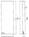
- the finished buttress 10 according to the invention, as illustrated in Figure 7 of the accompanying drawings, comprises an elongate member 12 which is substantially cuboid-shaped.
- the buttress 10 according to the invention is formed by longitudinally fastening two layers of fabric 34, 36 together, by means of second and third seams 14, 16 respectively.
- the free ends 22,22' of the fabric are fastened together by a transversely extending first seam 18.
- the buttress 10 according to the invention may be rendered radiopaque by either impregnating the fabric with a radiopaque material (not shown) or by providing a radiopaque material (20) in the form of a filament within the lumin of the buttress 10. It will be appreciated that the buttress 10 according to the invention, in itself, is not necessarily radiopaque and it may be desirable to render it radiopaque, in order to be able to observe, in vivo, the movement of the annulus during the cardiac cycle and the location of the buttress 10 within the annulus.
- the buttress 10 according to the present invention is composed of Teflon MS 010 fabric supplied by Bard of the United Kingdom. Tissue in-growth has been demonstrated to occur reliably when Teflon (Trade Mark) is used in a buttress 10 according to the invention. It will be appreciated that any suitable inert, non-degradable and sufficiently elastic (i.e. expandable and contractable) woven or knitted fabric of medical grade and supportive of tissue in-growth may be used in place of Teflon MS 010. It will also be appreciated that the elastic nature of the fabric may arise because of its mechanical structure and/or its chemical composition. A suitable fabric must, of course, be sufficiently elastic to support the damaged annulus and to permit normal (or almost normal) physiological annular movement during the cardiac cycle.
- the fabric should be sufficiently elastic to permit longitudinal elongation to no more than 150%, preferably to no more than 125%, most preferably to 105-108% of its unextended length.
- the fabric should also be transversely extendible, to accommodate non-planar movement of the annulus during the cardiac cycle.
- the fabric should be sufficiently elastic to permit the 25% increase in atrioventricular valve orifice surface area which occurs during each cardiac cycle.
- woven or knitted fabrics may be used including fabrics derived from polytetrafluoroethylene (e.g., GoreTex (Trade Mark) and Teflon (Trade Mark)) and from polyethylene terephthalate (e.g., Dacron (Trade Mark)).
- the Teflon fabric sheet is placed on a designated clean work surface, "right side” up, with the ribs running directly away from the operator (ribs partially shown in Figure 1). The operator cuts parallel with the ribs, to remove any frayed and/or partial ribs from the right hand side of the sheet. The operator then cuts a column of fabric of width "B", measuring from right to left.
- the appropriate column width is obtained using, for example, the dimensional information from Table 1 and the relevant measurement is marked with a straight pen. If the measurement falls in the middle of a rib, the pin is moved to the right so that the cut will be made between ribs. A slight cut is made with scissors and the pin is then removed. Cutting is then continued between the ribs from the bottom to the top of the fabric sheet, thereby separating an individual column having the width "B" from the main sheet (see Figure 1). Further individual columns are then cut by repeating the above steps to yield the desired quantity of fabric columns.
- the column of width "B” is then placed "wrong side” up, and twisted through 90°, so that the ribs are running longways, away from the operator (ribs partially shown in Figure 2).
- the width of the desired cuff is measured by referring to, for example, the cuff width "B" specified in Table 1, measuring from left to right.
- the desired measurement is marked with a straight pin and a slight cut is made with a scissors.
- the pin is then removed and cutting is continued until an individual cuff has been detached from the column, ensuring at all times that cutting is between the ribs.
- an individual cuff having the dimensions "B" X "C” is obtained (see Figure 2).
- the first seam 18 is made using an approximately 50cm length of 5/0 white suture comprising, for example, Filodell coated, virgin braided polyester surgical suture having a diameter of 0.12 ⁇ 0.025 mm (0.0048 ⁇ 0.001 in).
- a suitable suture is supplied by Purcell Sutures of the United Kingdom.
- the 5/0 white suture is threaded through a size 10B needle, whereupon both thread ends are joined and secured by tying a 1/2 overhand knot (left over right, right over left). The excess thread ends are then trimmed as close to the knot as is possible.
- the threaded needle is then inserted through the right side, making one back stitch (make a stitch, go back over the last stitch one more time), ensuring that the fabric ends are within the stitch.
- the same stitching pattern is then continued to the end of the seam, ensuring an even tension along the first seam 18. The operator should avoid pulling the thread too tight as this will cause distortion of the first seam 18.
- the last stitch is placed as for the first stitch, ensuring that the edge of the fabric is taken into the stitch.
- the needle is then passed through the loop and the thread is gently pulled until the loop closes making a loop knot, thereby securing the end.
- the thread is then trimmed as close to the knot as is possible.
- the first seam 18 is then opened and flattened with a steel ruler and excess material is trimmed off (not shown).
- the first seam 18 is then positioned adjacent the transverse mid-line of the cuff 12 (see Figure 3).
- An approximately 70cm length of 5/0 white suture is threaded through a size 10B needle. Both thread ends are joined and secured by tying a 1/2 overhand knot and the excess thread ends are trimmed as close to the knot as is possible.
- a second seam 14 see Figure 4
- the threaded needle is inserted approximately 3mm from the respective superimposed selvedges or fabric edges 24,24' and the needle is inserted through the "right side", making one back stitch ensuring that the ends are within the stitch and bringing the needle through the second seam 14 line. Stitching is continued in the same pattern until approximately one third of the second seam 14 is complete.
- the needle is then inserted back into the back stitch already made, making a securing stitch 26 in the second seam 14.
- the normal stitching pattern is then continued until approximately two thirds of the second seam 14 has been completed and, again, a securing double back stitch 26 is made.
- the normal stitching pattern is then continued to the end of the second seam 14, ensuring an even tension throughout. The operator should avoid pulling the thread too tight as this will cause distortion of the second seam 14.
- the last stitch is placed as for the first stitch, ensuring the edge of the fabric is taken into the stitch.
- the needle is then run back through the final back stitch making a loop in which the needle is passed through.
- the thread is then gently pulled until the loop closes making a loop knot and securing the end.
- the thread is trimmed as close to the knot as is possible.
- a suitable radiopaque material 20 comprises radiopaque silicone filaments having a 1.0 ⁇ 0.5mm diameter, which are obtained from Speciality Silicone Fabricators, Inc. of 3077 Rollie Gates Drive, Paso Robles, California 93446, United States of America under the Trade Name SSF-METN-750.
- a filament has a minimum tensile strength of 8,3 MPa (1200 p.s.i)., a minimum elongation of 750% and a minimum tear strength of 175,1 N/m (200 ppi).
- the silicone filament is cut into the desired length (see Table 2) using a scissors, a sharp blade or the like, ensuring that an even clean cut is made, which is free from tears, punctures, etc.
- the silicone strip 20 is then inserted into the buttress 10 by placing it flatagainst the second seam 14, ensuring it is not twisted or creased (see Figure 6 in which the radiopaque strip 20 is illustrated in dotted outline).
- a third seam 16 is made using a 70cm length of 5/0 white suture, which is threaded through a size 10B needle. A 1/2 overhand knot is made and excess thread is trimmed, single suture being used for this seam 16.
- Each of the right hand superimposed selvedges or fabric edges 28,28' of the cuff 12 are then folded inwardly to the extent necessary to ensure that the finished buttress 10 conforms to the dimensions specified in Table 2.
- the threaded needle is inserted, to make a back stitch.
- the stitches are picked up by sewing 1mm hemming stitch on alternate sides of the seam 16. All stitches are taken in a slightly different area to prevent fatiguing of the fabric. Again, when approximately one third of the third seam 16 is stitched, a securing loop stitch 30 is made.
- the stitching pattern is continued, folding both sides 28,28' evenly, until approximately two-thirds of the third seam 16 is complete and, again, a securing loop stitch 30 is made.
- the stitching pattern is then continued to the end of the third seam 16 ensuring that the thread is not pulled too tight, so as to cause distortion of the third seam 16.
- the operator finishes with a securing loop stitch and the needle is inserted into the corner of the cuff 12.
- the needle is then brought up through the flat of the cuff 12 on the same side as the first seam 18, approximately 10mm from the edge, ensuring that the needle does not contact the silicone strip 20.
- a 1mm double back stitch is made, with a loop on the last back stitch to secure the thread.
- the thread is then buried for another 2mm and excess thread is clipped as close to the fabric as is possible.
- An indicator 32 (visible in Figure 12) is attached using a 50cm length of 5/0 green suture, which is threaded through a size 10B needle.
- the indicator 32 which may be star-shaped, is made on the first seam-less side of the cuff 12 adjacent the transverse mid-line. This is achieved by inserting the needle into the surface of the fabric making a securing back stitch approximately 10mm from the transverse mid-line. The needle is moved to form a longitudinal stitch and a transverse stitch is then placed through the centre of the longitudinal stitch, thereby forming the "star" shape. The needle is then re-inserted in the surface of the fabric coming up approximately 10mm on the opposite side of the indicator 32 and a securing back stitch is made.
- the thread is then buried and trimmed as close as is possible to the surface of the fabric.
- the star indicator 32 serves to flatten the profile of the buttress 10 adjacent the transverse mid-line since, otherwise, the buttress 10 tends to protrude due to the volume displaced by the longitudinal edges 22, 22' of the first seam 18.
- the buttress 10 according to the invention is sutured into the mitral annulus, with the first seam 18 adjacent the mitral annulus itself, so that the indicator 32 faces the orifice and identifies the transverse mid-line of the buttress 10 according to the invention.
- the buttress 10 When the buttress 10 according to the invention is initially formed, the buttress 10 is cuboid and, therefore, extends in a substantially rectilinear direction.
- the trimmed fabric edges 24,24' of the second seam 14 and the fabric edges 28,28' of the third seam 16 each extend inwardly, facing each other, within the elongate member 12. These inwardly extending fabric edges 24,24',28,28' provide sufficient structural integrity so that the buttress 10 can, in use, support the damaged annulus so as to restore normal annular function.
- the buttress 10 according to the invention may be supplied in a desired arcuate shape, on a holder as described and exemplified in the following Examples 4 and 5.
- the ring may be shaped to the desired shape by moulding the buttress 10 about a mould of the desired shape (not shown), attaching sutures to the longitudinal ends 38 of the buttress 10 followed by tying the sutures in place so that the desired shape is held. The mould may then be removed.
- sterilisation assists in maintaining the buttress 10 in the desired shape. It has been found that, during sterilisation, moisture is absorbed from the radiopaque material 20 and/or from the surrounding atmosphere - it is believed that this moisture absorbtion aids in maintaining the desired buttress 10 shape.
- Figures 8 and 9 illustrate a second embodiment of a buttress 110 according to the present invention, which comprises two superimposed layers 134,136 of fabric for example Teflon (a registered trade mark) felt.
- a suitable felt is manufactured by Meadox Medicals Incorporated of 111 Baurer Drive, Oakland, New Jersey 07436, United States of America, under the Trade Mark Meadox.
- the fabric has been fastened or sewn together by longitudinally extending second and third seams 114,116, following which the elongate member 112 is turned inside out (see Figure 9) using a crochet-type hook (not shown) so that the respective fabric edges 124, 124', 128, 128' of the second and third seams 114,116 extend inwardly within the elongate member 112, opposing each other, where they act as internal packing in the buttress 110 endowing it with a requisite small degree of rigidity.
- the fabric of one or both layers 134,136 is impregnated with a radiopaque material.
- the buttress 110 is finished off by tucking in the superimposed free ends 122,122' and by then forming a fourth seam (not shown) at each end 138 thereof.
- FIGS 10-12 of the accompanying drawings illustrate a third embodiment of a buttress 210 according to the present invention.
- the buttress 210 is formed from one layer of fabric, each longitudinal end 222,222' of which is folded in a reflex manner, to form the required two layers having longitudinal ends 238.
- the layers are then fastened together by longitudinally extending second and third seams 214,216.
- the elongate member 212 is then turned inside out (see Figures 11 and 12) using a crochet-type hook (not shown) so that the respective fabric edges 224, 224', 228, 228' of the second and third seams 214,216 now extend inwardly, opposing each other.
- the ends 238 of the elongate member 212 are smooth and closed and the buttress 210 is then closed by providing a first seam 218 at a lap joint 40.
- the buttress 210 can be shaped to a desired arcuate angle by shaping the buttress 210 about a mould (not shown), by suturing the free ends 238 to each other at the desired spacing (not shown) or in any other manner.
- FIG. 13 of the accompanying drawings illustrates a first type of a holder generally indicated as 50.
- the holder 50 comprises a circumferentially extending rim 52 having a circumferentially extending groove 54, which groove 54 extends over at least a part of the circumference of the rim 52.
- the groove 54 is shaped and dimensioned to accept a buttress 10, 110, 210 according to the present invention as will be described in greater detail hereinafter.
- a plurality of radially extending spokes 56 support the rim 52.
- Circumferentially arranged apertures 58, 58', 58'' are provided in the rim 52.
- FIGS 14A-H of the accompanying drawings illustrate a second embodiment of a holder 150.
- the holder 150 comprises a circumferentially extending rim 152, supported by radially extending spokes 156.
- a circumferentially extending groove 154 is provided to receive a buttress 10, 110, 210 according to the invention.
- the assembly should be performed on a designated clean work surface in a clean environment area.
- a suitable holder 150 is annular and includes six apertures, A1, A2, A3, B1, B2 and B3, each extending radially through the rim 152.
- the buttress 10, 110, 210 according to the present invention is assembled on the holder 150 in the following manner.
- a 50cm length of 2/0 green suture is threaded through a size 5B needle and a 1/2 overhand knot is made.
- the 2/0 green suture suitably comprises Filodell coated, virgin braided polyester surgical suture having a diameter of 0.32 ⁇ 0.025 mm (0.0125 ⁇ 0.001).
- a suitable suture is supplied by Purcell Sutures of the United Kingdom.
- the buttress 10, 110, 210 is positioned in the groove 154, so that, from above, the buttress 10, 110, 210 is not visible and fits snugly in the groove 154.
- the needle is then brought in through A2 and directly through B2 (see Figure 14B).
- the needle is then brought through the surface fabric of the buttress 10, 110, 210 to the right of B2 (see Figure 14C) making an approximately 1mm stitch on the buttress 10, 110, 210.
- the needle is then inserted through B3 and then A3 (see Figure 14D).
- the needle is then brought up through the middle of one longitudinal end 38 of the buttress 10, 110, 210 on the surface of the fabric making an approximately 1mm stitch.
- the needle is then placed over the middle of the opposite longitudinal end 38 and again a 1mm stitch is made on the surface of the fabric (see Figure 14E).
- the needle is then inserted through A1 and directly through B1 (see Figure 14F).
- the needle is then brought up through the surface of the fabric making a 1mm stitch to the left of B2 (see Figure 14G) and the needle is then brought back through B2 followed through A2 (see Figure 14H).
- both thread ends With both thread ends now in the same position, i.e., extending from A2, the thread is then gently pulled an even amount on either side, ensuring that the thread is not pulled too tight as this will cause distortion.
- the operator should then ensure that the buttress 10 is secure and firmly in place and four overhand knots are then begun. Upon completion, the thread ends are cut as close to the knot as is possible.
- an identification tag (not shown) may be attached to the buttress 10, 110, 210.
- Such an identification tag may carry a serial number.
- the identification tag may be attached using an approximately 50cm length of 5/0 white suture threaded into a size 10B needle.
- the assembled buttress 10, 110, 210 according to the invention and holder 150 may then be placed in a pouch which can be heat sealed.
- the buttress/holder When it is desired to perform annuloplasty using a buttress according to the present invention, the buttress/holder is removed from the pouch and offered to the annulus where the buttress is sutured into place. When the buttress is secured to the annulus, the green suture connecting the buttress to the holder is severed and the green suture and the holder are discarded. Since the buttress has been offered to the posterior aspect of the annulus extended beyond its unextended length, this urges the posterior aspect to contract, thereby restoring the normal resting orifice surface area.
- the buttress may be offered to the orifice without a holder.
- Figures 15 and 16 of the accompanying drawings illustrate alternative holders 250, 350.
- Figure 15 illustrates plan, side and sectional views of a pen-torus-shaped holder 250 having a scalloped flange 262 extending from the rim 252 of the pen-torus.
- Figure 16 illustrates plan, side and sectional views of a pen-toroid-shaped holder 350, having a scalloped flange 362 extending from the rim 352 of the pen-toroid.
- Assembly of a buttress 10, 110, 210 according to the present invention on each of these holders 250, 350 involves stitching the buttress 10, 110, 210 onto the holder 250, 350 by threading the needle through the apertures indicated in dotted outline on the respective sectional views.
- the buttress 10, 110, 210 is desirably elongated on the holder 250, 350 by gently pulling the suture threads evenly, before securely tying them.
- the overall 30 day hospital mortality was 8 of 261 patients (3%), whereas the 30 day hospital mortality for isolated mitral annuloplasty was 1 of 152 patients (0.65%).
- the actuarial 1 year, 5 year and 10 year survival rates were 96%, 93% and 90%, respectively.
- the re-operation free rates at 5 years and 10 years were 92% and 90%, respectively.
- the rigid closed ring Carpentier group of patients actuarially had an incidence of repair failure of three cases at a mean follow-up of one year.
- the mean follow-up for the 77 patients receiving a buttress according to the present invention is thirteen months, with two patients requiring re-operation for reconstruction failure.
- the ex-planted flexible buttress devices showed no technical fault, which compares most favourably with the rigid ring population.
- mitral reconstruction by annuloplasty using a buttress 10, 110, 210 according to the present invention is a stable durable repair with low mortality and low re-operation rates. Furthermore, correct positioning in the annulus and correct elongation of the buttress 10, 110, 210 according to the present invention, is facilitated by using a holder 50, 150, 250, 350.
Abstract
Description
| Buttress Size, Fabric Column and Cuff Dimensions | ||
| Buttress Size "A" | Fabric Column Width "B" (mm) | Cuff Fabric Dimension Length "C" (mm) |
| R30 | 128 | 10 |
| R32 | 136 | 10 |
| R34 | 144 | 10 |
| R36 | 152 | 10 |
| R38 | 160 | 10 |
| R40 | 168 | 10 |
Thus, the fabric should be sufficiently elastic to permit longitudinal elongation to no more than 150%, preferably to no more than 125%, most preferably to 105-108% of its unextended length. Optionally, the fabric should also be transversely extendible, to accommodate non-planar movement of the annulus during the cardiac cycle. In addition, the fabric should be sufficiently elastic to permit the 25% increase in atrioventricular valve orifice surface area which occurs during each cardiac cycle.
| Length of Radiopaque Material and Dimensions of Finished Buttress according to the invention | |||
| Buttress Size "A" | Radiopaque Silicone Length "D" (mm) | Finished Buttress Width "E" (mm) | Finished Buttress Length "F" (mm) |
| | 56 | 4.5 | 60 |
| R32 | 60 | 4.5 | 64 |
| R34 | 64 | 4.5 | 68 |
| R36 | 68 | 4.5 | 72 |
| R38 | 72 | 4.5 | 76 |
| R40 | 76 | 4.5 | 80 |
Claims (9)
- A buttress (10;110;210) for cardiac valve reconstruction, the buttress (10;110;210) comprising an open substantially ring-shaped elongate member (12;112;212) consisting of a fabric dimensioned to fit against the base of the cusps of the cardiac valve, the fabric being adapted to permit normal or almost normal physiological annular movement during a cardiac cycle by being longitudinally extendable to no more than 150%, preferably no more than 125%, more preferably about 105-108% of the length of the elongate member (12;112;212) in a non-extended condition.
- An apparatus for cardiac valve reconstruction, the apparatus comprising a holder (50;150;250;350) including a buttress receiving area (54;154;254;354), the area (54;154;254;354) having an open, substantially ring-shaped configuration; a buttress (10;110;210) comprising an open, substantially ring-shaped elongate member (12;112;212) terminating in respective free ends and consisting of a fabric, the fabric being longitudinally extendable to no more than 150%, preferably no more than 125%, more preferably about 105%-108% of the length of the elongate member (12;112;212) in a non-extended condition; and means for removably mounting the buttress on the buttress receiving area (54;154;254;354) of the holder (50;150;250;350) in an extended condition.
- An apparatus according to Claim 2, in which an arcuate spacing between the respective free ends (38;138;238) of the elongate member (12;112;212) is more than one quarter of the unextended length of the elongate member (12;112;212).
- An apparatus recording to Claim 2 or 3, in which the buttress receiving area (54;154;254;354) is provided on an arcuate rim (52;152;252;352) shaped and dimensioned to receive the buttress (10;110;210).
- An apparatus according to Claim 4, in which a groove (54;154;254;354) is provided in the rim (52;152;252;352), the groove (54;154;254;354) defining the buttress receiving area.
- An apparatus according to Claim 4, in which a scalloped flange (262;362) extends from the rim (252;352) and defines a buttress receiving area (254;354) between the flange (262;362) and the rim (252;352).
- An apparatus according to any one of Claims 4-6, in which the rim (52;152;252;352) is supported by a plurality of radially extending spokes (56;156;256;356).
- An apparatus according to any one of Claims 2-7, in which the mounting means is a length of suture thread, the suture thread being removably connected to the respective free ends (38;138;238) of the buttress (10;110;210) and the free ends of the length of suture thread being secured, under tension, so as to stretch the buttress (10;110;210) into the extended condition.
- An apparatus according to Claim 8 when dependent on any one of Claims 4-7, in which an aperture (58') is provided in the rim (52;152;252) intermediate the buttress receiving area (54;154;254), both free ends of the suture thread extending through the aperture (58') and being secured together, under such tension as to stretch the buttress (10;110;210) to the desired extended condition.
Applications Claiming Priority (3)
| Application Number | Priority Date | Filing Date | Title |
|---|---|---|---|
| IE950546 | 1995-07-17 | ||
| IE950546 | 1995-07-17 | ||
| PCT/IE1996/000041 WO1997003625A1 (en) | 1995-07-17 | 1996-07-17 | A buttress for cardiac valve reconstruction |
Publications (2)
| Publication Number | Publication Date |
|---|---|
| EP0840579A1 EP0840579A1 (en) | 1998-05-13 |
| EP0840579B1 true EP0840579B1 (en) | 2003-11-26 |
Family
ID=11040827
Family Applications (1)
| Application Number | Title | Priority Date | Filing Date |
|---|---|---|---|
| EP96925951A Expired - Lifetime EP0840579B1 (en) | 1995-07-17 | 1996-07-17 | A buttress for cardiac valve reconstruction |
Country Status (12)
| Country | Link |
|---|---|
| US (1) | US6019791A (en) |
| EP (1) | EP0840579B1 (en) |
| JP (1) | JPH11509126A (en) |
| CN (1) | CN1150865C (en) |
| AT (1) | ATE254892T1 (en) |
| AU (1) | AU720447C (en) |
| BR (1) | BR9609768A (en) |
| CA (1) | CA2227142A1 (en) |
| DE (1) | DE69630888T2 (en) |
| ES (1) | ES2211966T3 (en) |
| IE (1) | IES71161B2 (en) |
| WO (1) | WO1997003625A1 (en) |
Families Citing this family (146)
| Publication number | Priority date | Publication date | Assignee | Title |
|---|---|---|---|---|
| WO1999011200A1 (en) | 1997-08-28 | 1999-03-11 | Alfred Edward Wood | Apparatus for selecting a suitably dimensioned buttress for a mitral valve |
| US6419695B1 (en) * | 2000-05-22 | 2002-07-16 | Shlomo Gabbay | Cardiac prosthesis for helping improve operation of a heart valve |
| US6726716B2 (en) | 2001-08-24 | 2004-04-27 | Edwards Lifesciences Corporation | Self-molding annuloplasty ring |
| WO2003020179A1 (en) * | 2001-08-31 | 2003-03-13 | Mitral Interventions | Apparatus for valve repair |
| US7101395B2 (en) | 2002-06-12 | 2006-09-05 | Mitral Interventions, Inc. | Method and apparatus for tissue connection |
| DE60307637T2 (en) * | 2002-06-17 | 2007-08-09 | Tyco Healthcare Group Lp, Norwalk | RINGTONE BRACKET STRUCTURE |
| US8128692B2 (en) * | 2004-02-27 | 2012-03-06 | Aortx, Inc. | Prosthetic heart valves, scaffolding structures, and systems and methods for implantation of same |
| JP2008510515A (en) * | 2004-08-17 | 2008-04-10 | タイコ ヘルスケア グループ エルピー | Stapling support structure |
| US8372094B2 (en) | 2004-10-15 | 2013-02-12 | Covidien Lp | Seal element for anastomosis |
| EP2441396B1 (en) | 2004-10-18 | 2015-01-21 | Covidien LP | Annular adhesive structure |
| US7845536B2 (en) | 2004-10-18 | 2010-12-07 | Tyco Healthcare Group Lp | Annular adhesive structure |
| US7938307B2 (en) * | 2004-10-18 | 2011-05-10 | Tyco Healthcare Group Lp | Support structures and methods of using the same |
| CN101340861B (en) * | 2005-02-28 | 2011-08-10 | 梅德坦提亚国际有限公司 | Devices and a kit for improving the function of a heart valve |
| US9364229B2 (en) | 2005-03-15 | 2016-06-14 | Covidien Lp | Circular anastomosis structures |
| US7942890B2 (en) * | 2005-03-15 | 2011-05-17 | Tyco Healthcare Group Lp | Anastomosis composite gasket |
| US20070203510A1 (en) * | 2006-02-28 | 2007-08-30 | Bettuchi Michael J | Annular disk for reduction of anastomotic tension and methods of using the same |
| US20100012703A1 (en) * | 2005-05-05 | 2010-01-21 | Allison Calabrese | Surgical Gasket |
| US20100016888A1 (en) * | 2005-05-05 | 2010-01-21 | Allison Calabrese | Surgical Gasket |
| US7739971B2 (en) * | 2005-06-07 | 2010-06-22 | Edwards Lifesciences Corporation | Systems and methods for assembling components of a fabric-covered prosthetic heart valve |
| US9629626B2 (en) * | 2006-02-02 | 2017-04-25 | Covidien Lp | Mechanically tuned buttress material to assist with proper formation of surgical element in diseased tissue |
| US7793813B2 (en) * | 2006-02-28 | 2010-09-14 | Tyco Healthcare Group Lp | Hub for positioning annular structure on a surgical device |
| WO2008057281A2 (en) | 2006-10-26 | 2008-05-15 | Tyco Healthcare Group Lp | Methods of using shape memory alloys for buttress attachment |
| US7845533B2 (en) | 2007-06-22 | 2010-12-07 | Tyco Healthcare Group Lp | Detachable buttress material retention systems for use with a surgical stapling device |
| US8011550B2 (en) * | 2009-03-31 | 2011-09-06 | Tyco Healthcare Group Lp | Surgical stapling apparatus |
| US8011555B2 (en) | 2007-03-06 | 2011-09-06 | Tyco Healthcare Group Lp | Surgical stapling apparatus |
| AU2008223389B2 (en) | 2007-03-06 | 2013-07-11 | Covidien Lp | Surgical stapling apparatus |
| JP2008258530A (en) * | 2007-04-09 | 2008-10-23 | Rohm Co Ltd | Semiconductor light-emitting device |
| US8038045B2 (en) | 2007-05-25 | 2011-10-18 | Tyco Healthcare Group Lp | Staple buttress retention system |
| US7950561B2 (en) * | 2007-06-18 | 2011-05-31 | Tyco Healthcare Group Lp | Structure for attachment of buttress material to anvils and cartridges of surgical staplers |
| US7665646B2 (en) | 2007-06-18 | 2010-02-23 | Tyco Healthcare Group Lp | Interlocking buttress material retention system |
| US8062330B2 (en) | 2007-06-27 | 2011-11-22 | Tyco Healthcare Group Lp | Buttress and surgical stapling apparatus |
| US10456259B2 (en) | 2008-04-16 | 2019-10-29 | Heart Repair Technologies, Inc. | Transvalvular intraannular band for mitral valve repair |
| US20100121437A1 (en) | 2008-04-16 | 2010-05-13 | Cardiovascular Technologies, Llc | Transvalvular intraannular band and chordae cutting for ischemic and dilated cardiomyopathy |
| US11083579B2 (en) | 2008-04-16 | 2021-08-10 | Heart Repair Technologies, Inc. | Transvalvular intraanular band and chordae cutting for ischemic and dilated cardiomyopathy |
| US11013599B2 (en) | 2008-04-16 | 2021-05-25 | Heart Repair Technologies, Inc. | Percutaneous transvalvular intraannular band for mitral valve repair |
| US20100121435A1 (en) | 2008-04-16 | 2010-05-13 | Cardiovascular Technologies, Llc | Percutaneous transvalvular intrannular band for mitral valve repair |
| US20100131057A1 (en) | 2008-04-16 | 2010-05-27 | Cardiovascular Technologies, Llc | Transvalvular intraannular band for aortic valve repair |
| US20100147921A1 (en) * | 2008-12-16 | 2010-06-17 | Lee Olson | Surgical Apparatus Including Surgical Buttress |
| US7988027B2 (en) * | 2009-03-31 | 2011-08-02 | Tyco Healthcare Group Lp | Crimp and release of suture holding buttress material |
| US7967179B2 (en) | 2009-03-31 | 2011-06-28 | Tyco Healthcare Group Lp | Center cinch and release of buttress material |
| US8365972B2 (en) | 2009-03-31 | 2013-02-05 | Covidien Lp | Surgical stapling apparatus |
| US8348126B2 (en) | 2009-03-31 | 2013-01-08 | Covidien Lp | Crimp and release of suture holding buttress material |
| US9486215B2 (en) | 2009-03-31 | 2016-11-08 | Covidien Lp | Surgical stapling apparatus |
| US8016178B2 (en) | 2009-03-31 | 2011-09-13 | Tyco Healthcare Group Lp | Surgical stapling apparatus |
| US9610080B2 (en) | 2009-10-15 | 2017-04-04 | Covidien Lp | Staple line reinforcement for anvil and cartridge |
| US8157151B2 (en) | 2009-10-15 | 2012-04-17 | Tyco Healthcare Group Lp | Staple line reinforcement for anvil and cartridge |
| US10842485B2 (en) | 2009-10-15 | 2020-11-24 | Covidien Lp | Brachytherapy buttress |
| US20150231409A1 (en) | 2009-10-15 | 2015-08-20 | Covidien Lp | Buttress brachytherapy and integrated staple line markers for margin identification |
| US9693772B2 (en) | 2009-10-15 | 2017-07-04 | Covidien Lp | Staple line reinforcement for anvil and cartridge |
| US10293553B2 (en) | 2009-10-15 | 2019-05-21 | Covidien Lp | Buttress brachytherapy and integrated staple line markers for margin identification |
| US8348130B2 (en) | 2010-12-10 | 2013-01-08 | Covidien Lp | Surgical apparatus including surgical buttress |
| US9084602B2 (en) | 2011-01-26 | 2015-07-21 | Covidien Lp | Buttress film with hemostatic action for surgical stapling apparatus |
| US8479968B2 (en) | 2011-03-10 | 2013-07-09 | Covidien Lp | Surgical instrument buttress attachment |
| US8789737B2 (en) | 2011-04-27 | 2014-07-29 | Covidien Lp | Circular stapler and staple line reinforcement material |
| US8998059B2 (en) | 2011-08-01 | 2015-04-07 | Ethicon Endo-Surgery, Inc. | Adjunct therapy device having driver with cavity for hemostatic agent |
| US9492170B2 (en) | 2011-08-10 | 2016-11-15 | Ethicon Endo-Surgery, Inc. | Device for applying adjunct in endoscopic procedure |
| US8998060B2 (en) | 2011-09-13 | 2015-04-07 | Ethicon Endo-Surgery, Inc. | Resistive heated surgical staple cartridge with phase change sealant |
| US9101359B2 (en) | 2011-09-13 | 2015-08-11 | Ethicon Endo-Surgery, Inc. | Surgical staple cartridge with self-dispensing staple buttress |
| US9999408B2 (en) | 2011-09-14 | 2018-06-19 | Ethicon Endo-Surgery, Inc. | Surgical instrument with fluid fillable buttress |
| US8814025B2 (en) | 2011-09-15 | 2014-08-26 | Ethicon Endo-Surgery, Inc. | Fibrin pad matrix with suspended heat activated beads of adhesive |
| US9254180B2 (en) | 2011-09-15 | 2016-02-09 | Ethicon Endo-Surgery, Inc. | Surgical instrument with staple reinforcement clip |
| US9125649B2 (en) | 2011-09-15 | 2015-09-08 | Ethicon Endo-Surgery, Inc. | Surgical instrument with filled staple |
| US9393018B2 (en) | 2011-09-22 | 2016-07-19 | Ethicon Endo-Surgery, Inc. | Surgical staple assembly with hemostatic feature |
| US9198644B2 (en) | 2011-09-22 | 2015-12-01 | Ethicon Endo-Surgery, Inc. | Anvil cartridge for surgical fastening device |
| US8985429B2 (en) | 2011-09-23 | 2015-03-24 | Ethicon Endo-Surgery, Inc. | Surgical stapling device with adjunct material application feature |
| US8899464B2 (en) | 2011-10-03 | 2014-12-02 | Ethicon Endo-Surgery, Inc. | Attachment of surgical staple buttress to cartridge |
| US9089326B2 (en) | 2011-10-07 | 2015-07-28 | Ethicon Endo-Surgery, Inc. | Dual staple cartridge for surgical stapler |
| US9675351B2 (en) | 2011-10-26 | 2017-06-13 | Covidien Lp | Buttress release from surgical stapler by knife pushing |
| US8584920B2 (en) | 2011-11-04 | 2013-11-19 | Covidien Lp | Surgical stapling apparatus including releasable buttress |
| US9010608B2 (en) | 2011-12-14 | 2015-04-21 | Covidien Lp | Releasable buttress retention on a surgical stapler |
| US9351732B2 (en) | 2011-12-14 | 2016-05-31 | Covidien Lp | Buttress attachment to degradable polymer zones |
| US9351731B2 (en) | 2011-12-14 | 2016-05-31 | Covidien Lp | Surgical stapling apparatus including releasable surgical buttress |
| US8967448B2 (en) | 2011-12-14 | 2015-03-03 | Covidien Lp | Surgical stapling apparatus including buttress attachment via tabs |
| US9113885B2 (en) | 2011-12-14 | 2015-08-25 | Covidien Lp | Buttress assembly for use with surgical stapling device |
| US9237892B2 (en) | 2011-12-14 | 2016-01-19 | Covidien Lp | Buttress attachment to the cartridge surface |
| US9326773B2 (en) | 2012-01-26 | 2016-05-03 | Covidien Lp | Surgical device including buttress material |
| US9010612B2 (en) | 2012-01-26 | 2015-04-21 | Covidien Lp | Buttress support design for EEA anvil |
| US9010609B2 (en) | 2012-01-26 | 2015-04-21 | Covidien Lp | Circular stapler including buttress |
| US9931116B2 (en) | 2012-02-10 | 2018-04-03 | Covidien Lp | Buttress composition |
| US8820606B2 (en) | 2012-02-24 | 2014-09-02 | Covidien Lp | Buttress retention system for linear endostaplers |
| US9572576B2 (en) | 2012-07-18 | 2017-02-21 | Covidien Lp | Surgical apparatus including surgical buttress |
| US20140048580A1 (en) | 2012-08-20 | 2014-02-20 | Covidien Lp | Buttress attachment features for surgical stapling apparatus |
| US9161753B2 (en) | 2012-10-10 | 2015-10-20 | Covidien Lp | Buttress fixation for a circular stapler |
| US9192384B2 (en) | 2012-11-09 | 2015-11-24 | Covidien Lp | Recessed groove for better suture retention |
| US20140131418A1 (en) | 2012-11-09 | 2014-05-15 | Covidien Lp | Surgical Stapling Apparatus Including Buttress Attachment |
| US9295466B2 (en) | 2012-11-30 | 2016-03-29 | Covidien Lp | Surgical apparatus including surgical buttress |
| US9681936B2 (en) | 2012-11-30 | 2017-06-20 | Covidien Lp | Multi-layer porous film material |
| US9402627B2 (en) | 2012-12-13 | 2016-08-02 | Covidien Lp | Folded buttress for use with a surgical apparatus |
| US9522002B2 (en) | 2012-12-13 | 2016-12-20 | Covidien Lp | Surgical instrument with pressure distribution device |
| US9204881B2 (en) | 2013-01-11 | 2015-12-08 | Covidien Lp | Buttress retainer for EEA anvil |
| US9433420B2 (en) | 2013-01-23 | 2016-09-06 | Covidien Lp | Surgical apparatus including surgical buttress |
| US9414839B2 (en) | 2013-02-04 | 2016-08-16 | Covidien Lp | Buttress attachment for circular stapling device |
| US9192383B2 (en) | 2013-02-04 | 2015-11-24 | Covidien Lp | Circular stapling device including buttress material |
| US9504470B2 (en) | 2013-02-25 | 2016-11-29 | Covidien Lp | Circular stapling device with buttress |
| US20140239047A1 (en) | 2013-02-28 | 2014-08-28 | Covidien Lp | Adherence concepts for non-woven absorbable felt buttresses |
| US9782173B2 (en) | 2013-03-07 | 2017-10-10 | Covidien Lp | Circular stapling device including buttress release mechanism |
| US9655620B2 (en) | 2013-10-28 | 2017-05-23 | Covidien Lp | Circular surgical stapling device including buttress material |
| US9844378B2 (en) | 2014-04-29 | 2017-12-19 | Covidien Lp | Surgical stapling apparatus and methods of adhering a surgical buttress thereto |
| US10835216B2 (en) | 2014-12-24 | 2020-11-17 | Covidien Lp | Spinneret for manufacture of melt blown nonwoven fabric |
| US10470767B2 (en) | 2015-02-10 | 2019-11-12 | Covidien Lp | Surgical stapling instrument having ultrasonic energy delivery |
| EP3291745A4 (en) | 2015-04-10 | 2019-02-13 | Covidien LP | Surgical stapler with integrated bladder |
| US10499918B2 (en) * | 2015-10-29 | 2019-12-10 | Ethicon Llc | Surgical stapler buttress assembly with features to interact with movable end effector components |
| US10959731B2 (en) | 2016-06-14 | 2021-03-30 | Covidien Lp | Buttress attachment for surgical stapling instrument |
| US11026686B2 (en) | 2016-11-08 | 2021-06-08 | Covidien Lp | Structure for attaching buttress to anvil and/or cartridge of surgical stapling instrument |
| AU2017382273A1 (en) | 2016-12-22 | 2019-08-08 | Heart Repair Technologies, Inc. | Percutaneous delivery systems for anchoring an implant in a cardiac valve annulus |
| US10874768B2 (en) | 2017-01-20 | 2020-12-29 | Covidien Lp | Drug eluting medical device |
| US10925607B2 (en) | 2017-02-28 | 2021-02-23 | Covidien Lp | Surgical stapling apparatus with staple sheath |
| US10368868B2 (en) | 2017-03-09 | 2019-08-06 | Covidien Lp | Structure for attaching buttress material to anvil and cartridge of surgical stapling instrument |
| US11096610B2 (en) | 2017-03-28 | 2021-08-24 | Covidien Lp | Surgical implants including sensing fibers |
| US10849625B2 (en) | 2017-08-07 | 2020-12-01 | Covidien Lp | Surgical buttress retention systems for surgical stapling apparatus |
| US10945733B2 (en) | 2017-08-23 | 2021-03-16 | Covidien Lp | Surgical buttress reload and tip attachment assemblies for surgical stapling apparatus |
| US11141151B2 (en) | 2017-12-08 | 2021-10-12 | Covidien Lp | Surgical buttress for circular stapling |
| CN111448345B (en) * | 2017-12-15 | 2022-03-25 | 东丽株式会社 | Woven fabric and method for producing same |
| US11065000B2 (en) | 2018-02-22 | 2021-07-20 | Covidien Lp | Surgical buttresses for surgical stapling apparatus |
| US10758237B2 (en) | 2018-04-30 | 2020-09-01 | Covidien Lp | Circular stapling apparatus with pinned buttress |
| US11284896B2 (en) | 2018-05-09 | 2022-03-29 | Covidien Lp | Surgical buttress loading and attaching/detaching assemblies |
| US11432818B2 (en) | 2018-05-09 | 2022-09-06 | Covidien Lp | Surgical buttress assemblies |
| US11426163B2 (en) | 2018-05-09 | 2022-08-30 | Covidien Lp | Universal linear surgical stapling buttress |
| US11219460B2 (en) | 2018-07-02 | 2022-01-11 | Covidien Lp | Surgical stapling apparatus with anvil buttress |
| US10806459B2 (en) | 2018-09-14 | 2020-10-20 | Covidien Lp | Drug patterned reinforcement material for circular anastomosis |
| US10952729B2 (en) | 2018-10-03 | 2021-03-23 | Covidien Lp | Universal linear buttress retention/release assemblies and methods |
| US11730472B2 (en) | 2019-04-25 | 2023-08-22 | Covidien Lp | Surgical system and surgical loading units thereof |
| US11596403B2 (en) | 2019-05-08 | 2023-03-07 | Covidien Lp | Surgical stapling device |
| US11478245B2 (en) | 2019-05-08 | 2022-10-25 | Covidien Lp | Surgical stapling device |
| US11571208B2 (en) | 2019-10-11 | 2023-02-07 | Covidien Lp | Surgical buttress loading units |
| US11523824B2 (en) | 2019-12-12 | 2022-12-13 | Covidien Lp | Anvil buttress loading for a surgical stapling apparatus |
| US11547407B2 (en) | 2020-03-19 | 2023-01-10 | Covidien Lp | Staple line reinforcement for surgical stapling apparatus |
| US11337699B2 (en) | 2020-04-28 | 2022-05-24 | Covidien Lp | Magnesium infused surgical buttress for surgical stapler |
| US11707276B2 (en) | 2020-09-08 | 2023-07-25 | Covidien Lp | Surgical buttress assemblies and techniques for surgical stapling |
| US11559306B2 (en) | 2020-09-16 | 2023-01-24 | Cilag Gmbh International | Apparatus and method to detect full seating of buttress applicator in end effector of surgical stapler |
| US11660093B2 (en) | 2020-09-16 | 2023-05-30 | Cilag Gmbh International | Method of applying buttress to end effector of surgical stapler |
| US11452523B2 (en) | 2020-09-16 | 2022-09-27 | Cilag Gmbh International | Apparatus and method to apply buttresses separately to jaws of end effector of surgical stapler |
| US11413040B2 (en) * | 2020-09-16 | 2022-08-16 | Cilag Gmbh International | Apparatus and method to apply buttress to end effector of surgical stapler with authentication |
| US11564683B2 (en) | 2020-09-16 | 2023-01-31 | Cilag Gmbh International | Apparatus and method to apply buttress to end effector of surgical stapler via driven member |
| US11766261B2 (en) | 2020-09-16 | 2023-09-26 | Cilag Gmbh International | Apparatus and method to apply buttress to end effector of surgical stapler via fixed base |
| US11419605B2 (en) | 2020-09-16 | 2022-08-23 | Cilag Gmbh International | Apparatus and method to close end effector of surgical stapler onto buttress |
| US11399833B2 (en) | 2020-10-19 | 2022-08-02 | Covidien Lp | Anvil buttress attachment for surgical stapling apparatus |
| US11534170B2 (en) | 2021-01-04 | 2022-12-27 | Covidien Lp | Anvil buttress attachment for surgical stapling apparatus |
| US11510670B1 (en) | 2021-06-23 | 2022-11-29 | Covidien Lp | Buttress attachment for surgical stapling apparatus |
| US11596399B2 (en) | 2021-06-23 | 2023-03-07 | Covidien Lp | Anvil buttress attachment for surgical stapling apparatus |
| US11672538B2 (en) | 2021-06-24 | 2023-06-13 | Covidien Lp | Surgical stapling device including a buttress retention assembly |
| US11678879B2 (en) | 2021-07-01 | 2023-06-20 | Covidien Lp | Buttress attachment for surgical stapling apparatus |
| US11684368B2 (en) | 2021-07-14 | 2023-06-27 | Covidien Lp | Surgical stapling device including a buttress retention assembly |
| US11801052B2 (en) | 2021-08-30 | 2023-10-31 | Covidien Lp | Assemblies for surgical stapling instruments |
| US11751875B2 (en) | 2021-10-13 | 2023-09-12 | Coviden Lp | Surgical buttress attachment assemblies for surgical stapling apparatus |
| US11806017B2 (en) | 2021-11-23 | 2023-11-07 | Covidien Lp | Anvil buttress loading system for surgical stapling apparatus |
Family Cites Families (8)
| Publication number | Priority date | Publication date | Assignee | Title |
|---|---|---|---|---|
| FR2306671A1 (en) * | 1975-04-11 | 1976-11-05 | Rhone Poulenc Ind | VALVULAR IMPLANT |
| US4042979A (en) * | 1976-07-12 | 1977-08-23 | Angell William W | Valvuloplasty ring and prosthetic method |
| US4164046A (en) * | 1977-05-16 | 1979-08-14 | Cooley Denton | Valve prosthesis |
| IT1218951B (en) * | 1988-01-12 | 1990-04-24 | Mario Morea | PROSTHETIC DEVICE FOR SURGICAL CORRECTION OF TRICUSPIDAL INSUFFICENCE |
| US5290300A (en) * | 1989-07-31 | 1994-03-01 | Baxter International Inc. | Flexible suture guide and holder |
| JP2002509448A (en) * | 1992-01-27 | 2002-03-26 | メドトロニック インコーポレーテッド | Annular forming and suturing rings |
| US5522884A (en) * | 1993-02-19 | 1996-06-04 | Medtronic, Inc. | Holder for adjustable mitral & tricuspid annuloplasty rings |
| US5397348A (en) * | 1993-12-13 | 1995-03-14 | Carbomedics, Inc. | Mechanical heart valve with compressible stiffening ring |
-
1996
- 1996-07-17 WO PCT/IE1996/000041 patent/WO1997003625A1/en active IP Right Grant
- 1996-07-17 AU AU66289/96A patent/AU720447C/en not_active Ceased
- 1996-07-17 DE DE69630888T patent/DE69630888T2/en not_active Expired - Lifetime
- 1996-07-17 BR BR9609768A patent/BR9609768A/en not_active Application Discontinuation
- 1996-07-17 ES ES96925951T patent/ES2211966T3/en not_active Expired - Lifetime
- 1996-07-17 US US09/000,059 patent/US6019791A/en not_active Expired - Lifetime
- 1996-07-17 EP EP96925951A patent/EP0840579B1/en not_active Expired - Lifetime
- 1996-07-17 CN CNB961956305A patent/CN1150865C/en not_active Expired - Fee Related
- 1996-07-17 AT AT96925951T patent/ATE254892T1/en not_active IP Right Cessation
- 1996-07-17 JP JP9506507A patent/JPH11509126A/en active Pending
- 1996-07-17 IE IES960520 patent/IES71161B2/en not_active IP Right Cessation
- 1996-07-17 CA CA002227142A patent/CA2227142A1/en not_active Abandoned
Also Published As
| Publication number | Publication date |
|---|---|
| EP0840579A1 (en) | 1998-05-13 |
| ES2211966T3 (en) | 2004-07-16 |
| DE69630888D1 (en) | 2004-01-08 |
| AU720447C (en) | 2007-03-15 |
| JPH11509126A (en) | 1999-08-17 |
| CN1190879A (en) | 1998-08-19 |
| BR9609768A (en) | 1999-01-26 |
| WO1997003625A1 (en) | 1997-02-06 |
| CN1150865C (en) | 2004-05-26 |
| IES71161B2 (en) | 1997-01-29 |
| ATE254892T1 (en) | 2003-12-15 |
| CA2227142A1 (en) | 1997-02-06 |
| AU6628996A (en) | 1997-02-18 |
| US6019791A (en) | 2000-02-01 |
| AU720447B2 (en) | 2000-06-01 |
| DE69630888T2 (en) | 2004-09-02 |
Similar Documents
| Publication | Publication Date | Title |
|---|---|---|
| EP0840579B1 (en) | A buttress for cardiac valve reconstruction | |
| US20230181319A1 (en) | Device that can be implanted in a minimally invasive manner and mitral valve implant system | |
| US11376122B2 (en) | Holder and deployment system for surgical heart valves | |
| JP4057783B2 (en) | Annular ring with cut zone | |
| CA2900655C (en) | Rapidly deployable surgical heart valves | |
| EP0779793B1 (en) | Apparatus for reducing circumference of vascular structure | |
| US5041130A (en) | Flexible annuloplasty ring and holder | |
| US5961539A (en) | Method and apparatus for sizing, stabilizing and/or reducing the circumference of an anatomical structure | |
| EP2621408B1 (en) | Aortic valve devices | |
| US20130190862A1 (en) | Rapidly deployable surgical heart valves | |
| US20020128708A1 (en) | Annuloplasty system | |
| US20050065597A1 (en) | Aortic ring and ancillary device for implanting it | |
| CN102014797A (en) | Quick-release annuloplasty ring holder | |
| CN112022439A (en) | Artificial heart valve | |
| US20200237514A1 (en) | Method for manufacturing personalized naturally designed mitral prosthesis | |
| US11259925B2 (en) | Valve translocation device and method for the treatment of functional valve regurgitation | |
| US20210346154A1 (en) | Prosthetic Heart Valve With Radiopaque Elements | |
| US11324592B2 (en) | Naturally designed mitral prosthesis | |
| CN212788787U (en) | Artificial heart valve | |
| US20210290265A1 (en) | Surgical site support article | |
| US11872133B1 (en) | Valve translocation device and method for the treatment of functional valve |
Legal Events
| Date | Code | Title | Description |
|---|---|---|---|
| PUAI | Public reference made under article 153(3) epc to a published international application that has entered the european phase |
Free format text: ORIGINAL CODE: 0009012 |
|
| 17P | Request for examination filed |
Effective date: 19980217 |
|
| AK | Designated contracting states |
Kind code of ref document: A1 Designated state(s): AT BE CH DE DK ES FI FR GB GR IE IT LI LU MC NL PT SE |
|
| 111L | Licence recorded |
Free format text: 980615 0100 AORTECH EUROPE LIMITED |
|
| 17Q | First examination report despatched |
Effective date: 20020218 |
|
| GRAH | Despatch of communication of intention to grant a patent |
Free format text: ORIGINAL CODE: EPIDOS IGRA |
|
| GRAS | Grant fee paid |
Free format text: ORIGINAL CODE: EPIDOSNIGR3 |
|
| GRAA | (expected) grant |
Free format text: ORIGINAL CODE: 0009210 |
|
| AK | Designated contracting states |
Kind code of ref document: B1 Designated state(s): AT BE CH DE DK ES FI FR GB GR IE IT LI LU MC NL PT SE |
|
| PG25 | Lapsed in a contracting state [announced via postgrant information from national office to epo] |
Ref country code: NL Free format text: LAPSE BECAUSE OF FAILURE TO SUBMIT A TRANSLATION OF THE DESCRIPTION OR TO PAY THE FEE WITHIN THE PRESCRIBED TIME-LIMIT Effective date: 20031126 Ref country code: LI Free format text: LAPSE BECAUSE OF FAILURE TO SUBMIT A TRANSLATION OF THE DESCRIPTION OR TO PAY THE FEE WITHIN THE PRESCRIBED TIME-LIMIT Effective date: 20031126 Ref country code: FI Free format text: LAPSE BECAUSE OF FAILURE TO SUBMIT A TRANSLATION OF THE DESCRIPTION OR TO PAY THE FEE WITHIN THE PRESCRIBED TIME-LIMIT Effective date: 20031126 Ref country code: CH Free format text: LAPSE BECAUSE OF FAILURE TO SUBMIT A TRANSLATION OF THE DESCRIPTION OR TO PAY THE FEE WITHIN THE PRESCRIBED TIME-LIMIT Effective date: 20031126 Ref country code: BE Free format text: LAPSE BECAUSE OF FAILURE TO SUBMIT A TRANSLATION OF THE DESCRIPTION OR TO PAY THE FEE WITHIN THE PRESCRIBED TIME-LIMIT Effective date: 20031126 Ref country code: AT Free format text: LAPSE BECAUSE OF FAILURE TO SUBMIT A TRANSLATION OF THE DESCRIPTION OR TO PAY THE FEE WITHIN THE PRESCRIBED TIME-LIMIT Effective date: 20031126 |
|
| REG | Reference to a national code |
Ref country code: GB Ref legal event code: FG4D |
|
| REG | Reference to a national code |
Ref country code: CH Ref legal event code: EP |
|
| REF | Corresponds to: |
Ref document number: 69630888 Country of ref document: DE Date of ref document: 20040108 Kind code of ref document: P |
|
| REG | Reference to a national code |
Ref country code: IE Ref legal event code: FG4D |
|
| PG25 | Lapsed in a contracting state [announced via postgrant information from national office to epo] |
Ref country code: SE Free format text: LAPSE BECAUSE OF FAILURE TO SUBMIT A TRANSLATION OF THE DESCRIPTION OR TO PAY THE FEE WITHIN THE PRESCRIBED TIME-LIMIT Effective date: 20040226 Ref country code: GR Free format text: LAPSE BECAUSE OF FAILURE TO SUBMIT A TRANSLATION OF THE DESCRIPTION OR TO PAY THE FEE WITHIN THE PRESCRIBED TIME-LIMIT Effective date: 20040226 Ref country code: DK Free format text: LAPSE BECAUSE OF FAILURE TO SUBMIT A TRANSLATION OF THE DESCRIPTION OR TO PAY THE FEE WITHIN THE PRESCRIBED TIME-LIMIT Effective date: 20040226 |
|
| NLV1 | Nl: lapsed or annulled due to failure to fulfill the requirements of art. 29p and 29m of the patents act | ||
| 111L | Licence recorded |
Free format text: 0100 KOEHLER CHEMIE LIMITED Effective date: 20031120 |
|
| REG | Reference to a national code |
Ref country code: CH Ref legal event code: PL |
|
| REG | Reference to a national code |
Ref country code: ES Ref legal event code: FG2A Ref document number: 2211966 Country of ref document: ES Kind code of ref document: T3 |
|
| PG25 | Lapsed in a contracting state [announced via postgrant information from national office to epo] |
Ref country code: LU Free format text: LAPSE BECAUSE OF NON-PAYMENT OF DUE FEES Effective date: 20040717 |
|
| PG25 | Lapsed in a contracting state [announced via postgrant information from national office to epo] |
Ref country code: MC Free format text: LAPSE BECAUSE OF NON-PAYMENT OF DUE FEES Effective date: 20040731 |
|
| ET | Fr: translation filed | ||
| PLBE | No opposition filed within time limit |
Free format text: ORIGINAL CODE: 0009261 |
|
| STAA | Information on the status of an ep patent application or granted ep patent |
Free format text: STATUS: NO OPPOSITION FILED WITHIN TIME LIMIT |
|
| 26N | No opposition filed |
Effective date: 20040827 |
|
| PG25 | Lapsed in a contracting state [announced via postgrant information from national office to epo] |
Ref country code: IT Free format text: LAPSE BECAUSE OF NON-PAYMENT OF DUE FEES Effective date: 20050717 |
|
| PG25 | Lapsed in a contracting state [announced via postgrant information from national office to epo] |
Ref country code: PT Free format text: LAPSE BECAUSE OF NON-PAYMENT OF DUE FEES Effective date: 20040426 |
|
| PGRI | Patent reinstated in contracting state [announced from national office to epo] |
Ref country code: IT Effective date: 20110616 |
|
| REG | Reference to a national code |
Ref country code: FR Ref legal event code: PLFP Year of fee payment: 20 |
|
| PGFP | Annual fee paid to national office [announced via postgrant information from national office to epo] |
Ref country code: IE Payment date: 20150630 Year of fee payment: 20 |
|
| PGFP | Annual fee paid to national office [announced via postgrant information from national office to epo] |
Ref country code: ES Payment date: 20150723 Year of fee payment: 20 Ref country code: DE Payment date: 20150722 Year of fee payment: 20 Ref country code: GB Payment date: 20150701 Year of fee payment: 20 |
|
| PGFP | Annual fee paid to national office [announced via postgrant information from national office to epo] |
Ref country code: FR Payment date: 20150730 Year of fee payment: 20 |
|
| PGFP | Annual fee paid to national office [announced via postgrant information from national office to epo] |
Ref country code: IT Payment date: 20150728 Year of fee payment: 20 |
|
| REG | Reference to a national code |
Ref country code: DE Ref legal event code: R071 Ref document number: 69630888 Country of ref document: DE |
|
| REG | Reference to a national code |
Ref country code: GB Ref legal event code: PE20 Expiry date: 20160716 |
|
| REG | Reference to a national code |
Ref country code: IE Ref legal event code: MK9A |
|
| REG | Reference to a national code |
Ref country code: ES Ref legal event code: FD2A Effective date: 20161026 |
|
| PG25 | Lapsed in a contracting state [announced via postgrant information from national office to epo] |
Ref country code: GB Free format text: LAPSE BECAUSE OF EXPIRATION OF PROTECTION Effective date: 20160716 Ref country code: IE Free format text: LAPSE BECAUSE OF EXPIRATION OF PROTECTION Effective date: 20160717 |
|
| PG25 | Lapsed in a contracting state [announced via postgrant information from national office to epo] |
Ref country code: ES Free format text: LAPSE BECAUSE OF EXPIRATION OF PROTECTION Effective date: 20160718 |