EP0840186A1 - Transient-free gain switching - Google Patents
Transient-free gain switching Download PDFInfo
- Publication number
- EP0840186A1 EP0840186A1 EP97308682A EP97308682A EP0840186A1 EP 0840186 A1 EP0840186 A1 EP 0840186A1 EP 97308682 A EP97308682 A EP 97308682A EP 97308682 A EP97308682 A EP 97308682A EP 0840186 A1 EP0840186 A1 EP 0840186A1
- Authority
- EP
- European Patent Office
- Prior art keywords
- gain
- plant
- control system
- switching
- states
- Prior art date
- Legal status (The legal status is an assumption and is not a legal conclusion. Google has not performed a legal analysis and makes no representation as to the accuracy of the status listed.)
- Granted
Links
- 238000000034 method Methods 0.000 claims abstract description 26
- 230000000694 effects Effects 0.000 claims abstract description 7
- 230000015572 biosynthetic process Effects 0.000 claims abstract description 5
- 230000004044 response Effects 0.000 abstract description 23
- 238000011156 evaluation Methods 0.000 abstract 1
- 230000002401 inhibitory effect Effects 0.000 abstract 1
- 230000007774 longterm Effects 0.000 abstract 1
- 230000001052 transient effect Effects 0.000 description 9
- 230000008859 change Effects 0.000 description 8
- 238000005259 measurement Methods 0.000 description 7
- 230000001965 increasing effect Effects 0.000 description 6
- 238000001914 filtration Methods 0.000 description 4
- 230000006870 function Effects 0.000 description 4
- 230000008569 process Effects 0.000 description 4
- 238000010304 firing Methods 0.000 description 3
- 230000006399 behavior Effects 0.000 description 2
- 238000004891 communication Methods 0.000 description 2
- 238000012938 design process Methods 0.000 description 2
- 238000012545 processing Methods 0.000 description 2
- 230000009467 reduction Effects 0.000 description 2
- 238000012935 Averaging Methods 0.000 description 1
- 206010034719 Personality change Diseases 0.000 description 1
- 230000004913 activation Effects 0.000 description 1
- 230000009286 beneficial effect Effects 0.000 description 1
- 238000004364 calculation method Methods 0.000 description 1
- 239000002131 composite material Substances 0.000 description 1
- 230000001186 cumulative effect Effects 0.000 description 1
- 238000013461 design Methods 0.000 description 1
- 238000010586 diagram Methods 0.000 description 1
- 230000007717 exclusion Effects 0.000 description 1
- 230000001939 inductive effect Effects 0.000 description 1
- 230000010354 integration Effects 0.000 description 1
- 239000000314 lubricant Substances 0.000 description 1
- 238000012423 maintenance Methods 0.000 description 1
- 238000004519 manufacturing process Methods 0.000 description 1
- 230000010355 oscillation Effects 0.000 description 1
- 238000007619 statistical method Methods 0.000 description 1
- 239000000126 substance Substances 0.000 description 1
Images


Classifications
-
- G—PHYSICS
- G05—CONTROLLING; REGULATING
- G05B—CONTROL OR REGULATING SYSTEMS IN GENERAL; FUNCTIONAL ELEMENTS OF SUCH SYSTEMS; MONITORING OR TESTING ARRANGEMENTS FOR SUCH SYSTEMS OR ELEMENTS
- G05B13/00—Adaptive control systems, i.e. systems automatically adjusting themselves to have a performance which is optimum according to some preassigned criterion
- G05B13/02—Adaptive control systems, i.e. systems automatically adjusting themselves to have a performance which is optimum according to some preassigned criterion electric
- G05B13/0205—Adaptive control systems, i.e. systems automatically adjusting themselves to have a performance which is optimum according to some preassigned criterion electric not using a model or a simulator of the controlled system
- G05B13/024—Adaptive control systems, i.e. systems automatically adjusting themselves to have a performance which is optimum according to some preassigned criterion electric not using a model or a simulator of the controlled system in which a parameter or coefficient is automatically adjusted to optimise the performance
-
- B—PERFORMING OPERATIONS; TRANSPORTING
- B64—AIRCRAFT; AVIATION; COSMONAUTICS
- B64G—COSMONAUTICS; VEHICLES OR EQUIPMENT THEREFOR
- B64G1/00—Cosmonautic vehicles
- B64G1/22—Parts of, or equipment specially adapted for fitting in or to, cosmonautic vehicles
- B64G1/24—Guiding or controlling apparatus, e.g. for attitude control
- B64G1/244—Spacecraft control systems
Definitions
- This invention relates to a control system, such as a spacecraft attitude control system, having a choice of gains to be employed in a controller and in a compensator of the system and, more particularly, to a mode of switching between a high gain and a low gain without introduction of a significant transient.
- Control systems attempt to control a plant, such as a spacecraft, submarine, chemical plant, or manufacturing equipment, by way of example, by outputting desired quantities, such as motor torques and thruster assignments with on times, in response to the sum of these quantities and disturbances on the plant.
- desired quantities such as motor torques and thruster assignments with on times
- desired quantities such as motor torques and thruster assignments with on times
- the plant of primary interest is a spacecraft and, accordingly, this presentation will be in terms of a spacecraft, it being understood that the concepts presented herein apply also to other plants.
- a spacecraft employing an earth sensor to determine spacecraft attitude by observing the edges of the earth to provide an estimate of nadir, it is a practice to use thrusters and reaction wheels to reorient a spacecraft to maintain its attitude.
- a control system is configured as a feedback loop wherein a desired output is the spacecraft orientation and its rates.
- an estimator is employed to provide estimates of these quantities, these quantities being called the states of the spacecraft.
- An estimator is not required if direct, low noise measurements are available, or can be transformed into the direction of these states.
- Earth sensors and rate gyros are examples of sensors that can be used for direct measurements of the states of spacecraft orientation and rates.
- most spacecraft require pointing to higher accuracies than the earth sensor noise levels, thereby requiring some sort of filtering or estimation for the desired results.
- the difference between the desired set of states and the estimated (measured) set of states is known as the loop error signal.
- the estimator may process the signal outputted by one of the foregoing sensors, or may process signals outputted by a plurality of such sensors to provide estimates of the states of the plant being controlled. These estimates, when differenced with a set of desired states, provide the control system with a set of feedback signals. Estimating may involve averaging, statistical analysis and/or Kalman filtering, by way of example.
- the estimator may be provided with a relatively high gain for faster response with increased noise power output, or may be provided with a lower gain for slower response.
- a controller of an output quantity such as a rotational rate of the spacecraft, may be provided with a higher gain for faster response with increased noise power output, or may be provided with a lower gain for slower response and reduced noise power output.
- the higher gain may be used during a thruster firing, while lower gains may be used during quiescent periods.
- the disturbance function may be in the form of a disturbing torque produced, by way of example, by viscous friction of a lubricant on a reaction wheel or by the pressure of solar rays on a spacecraft.
- the disturbing torques can have a cumulative effect which require constant torque demands from the control system even after the loop error signal is driven to zero.
- some control system designs employ integral control states to generate a non-zero controller input signal in order to maintain these constant torque demands from the control system.
- Control systems can be implemented with analog or digital hardware.
- estimates of the plant states are generated with RLC (resistive, inductive, capacitive) circuits. These circuits filter the sensor outputs, which typically would be voltage levels, to the desired voltage levels for the control system to utilize. These output voltages are differenced with desired voltage levels to provide error signal inputs to the control system to use additional RLC circuits to generate output voltages to be sent to the actuators.
- sensor outputs would be converted to binary data for the onboard computer to utilize. These data would then be manipulated with algorithmic processing to provide estimates of the plant states.
- estimates are differenced with desired states to provide error signal inputs to the control system to use additional algorithmic processing to generate outputs to be sent to the actuators.
- one of the estimates could be the plant state corresponding to the orientation of the spacecraft, another estimate could be the integral of the difference between this estimate and the desired orientation of the spacecraft, another could be the integral of the difference between this state and the desired position of the spacecraft, or the raw integral of a sensor that measures that difference, a third state could be an estimate of the rate of spacecraft. Differences between these estimates, whether voltage levels or binary data, and the desired states provide a composite error signal to generate outputs to control actuators for improved response of the plant.
- a thruster would be employed to change the orientation of the spacecraft.
- a thruster In the case of the orienting of the spacecraft to correct a drifting away from a desired orientation, use may be made of reaction wheels. Maintaining a torque from the reaction wheels to the spacecraft to reject disturbance torques can cause the wheel speeds to increase beyond their safe operating speeds.
- a desired form of response of the momentum control system would be to activate a thruster to reduce the momentum of the spacecraft. This impulse would temporarily shift the orientation of the spacecraft.
- the wheel control system would respond by reducing the wheel speeds, thereby restoring the spacecraft's s desired orientation.
- control systems typically increase their gains when the plant being controlled enters a condition of increased disturbance, such as the reaction wheel control system responding to thruster firings.
- the present invention seeks to overcome or substantially reduce the effect of aforementioned problems.
- a method of operating a control system to inhibit formation of transients during a switching of a magnitude of the gains within the control system in order to drive a plant the control system having a controller, the method comprising, applying a drive signal to actuation means of the system for driving the plant, evaluating a difference between desired states of the plant and the estimates of the plant states to observe an occurrence of a magnitude of the difference which falls within a range of values satisfying a predetermined criteria, and switching a value of the gain during said occurrence.
- a method of operating a control system to inhibit formation of transients during a switching of a magnitude of the gains within the control system in order to drive a plant the system having a controller the method comprising, applying a drive signal to actuation means of the system for driving the plant, distinguishing between estimates of the states of the plant and integral control states, wherein the integral control states are generated within the control system to maintain drive signal to the actuation means to counter disturbances on the plant, evaluating a portion of a controller input signal which portion is exclusive of the integral control states and is comprised of a difference between desired states of the plant and the estimates of the plant states to observe an occurrence of a magnitude of the difference which falls within a range of values satisfying a predetermined criteria, switching a value of the gain during said occurrence; and concurrently with said switching step, scaling an amplitude of the integral state by a factor inverse to a ratio of switched gain values.
- a feedback control system may have a controller in a forward branch and an estimator in a feedback branch, to enable a switching of gain settings between relatively high and relatively low gain settings without introduction of a significant transient.
- An informational signal based on data from one or more sensors can provide a measure of the state of the plant and may be referred to hereinafter as a measurement signal.
- Such an informational signal which can be obtained in an open-loop control system, serves as a feed back signal in a closed-loop control system.
- the output quantities of the control system may be torque requests to the reaction wheels, and the disturbance may be due to solar pressure on the spacecraft or bearing drag on a reaction wheel of the spacecraft.
- the error feedback signal may have three components which are used by the controller to provide signals to the actuators which impart control to the spacecraft, thereby providing the desired response.
- One of these signals could be the error between the desired spacecraft orientation angle and the estimated angle.
- Another could be the error between the desired spacecraft rate of change in the orientation angle, and the estimated rate of change.
- Another optional may be the integral control state consisting of the integral of the first error signal mentioned in this paragraph, or the integral of the sensor output that measures this error directly. Further this provides a description of one axis of control; typically, there are three axes of control for a spacecraft. This means a triplication of the aforementioned signals.
- the foregoing aspects of the invention may be implemented as follows.
- the control process of the plant controller is observed for determining a suitable threshold for amplitude of the loop error signal below which the loop error has no more than a negligible effect on a plant actuator response.
- a suitable threshold for amplitude of the loop error signal below which the loop error has no more than a negligible effect on a plant actuator response.
- Such an actuator may be, by way of example, the foregoing reaction wheel or the foregoing thruster. This enables a person to determine criteria for maximum range of angle error and a maximum range of angle rate in which gain switching can be accomplished with little immediate effect on an actuator.
- the loop error signal is observed to find an interval wherein the criteria are met, whereupon the gain switching can be implemented.
- a condition of high gain may be present to adjust a spacecraft orientation until the spacecraft comes approximately into the desired orientation.
- naturally occurring oscillations of relatively small amplitude in the plant states bring the loop error signal into a region of amplitude which meets the foregoing criteria, so that switching can commence.
- each of the relevant integral states are scaled by a factor, up or down, to compensate for a decrease or increase, respectively, in the gain.
- the scaling factor is equal to the ratio of the gain before switching to the gain after switching. This insures that the component of the output signal of the feedback loop which counteracts the disturbance remains constant during a switching of gain. Waiting until the loop error signal meets the switching criteria reduces transients resulting from noisy state estimates coming from existing high gains in the filter/estimator, or switching to high controller gains when offsets exist, while adjusting the integral control states (when available) at the same time reduces transients resulting from constant disturbance on the system being controlled.
- a spacecraft 20 travels along a path 22 about the earth 24.
- the spacecraft 20 carries an earth sensor 26 which sights a point 28 on the earth's surface via a sight line 30.
- solar panels 32 which receive solar energy for powering electronic equipment 34 which provides functions of communication and control of spacecraft attitude.
- An antenna 36 on the spacecraft 20 provides for electromagnetic communication with an antenna 38 of a ground station 40 on the earth 24.
- Adjustment of spacecraft orientation is accomplished by thrusters 42, two of which are shown in Fig. 1, and by reaction wheels 44, one of which is shown in Fig. 1.
- Each reaction wheel 44 is connected via line 46 to a drive motor 48 which imparts rotation to the reaction wheel 44.
- the thrusters 42 and the reaction wheels 44 are operated by a control system 50 (shown in Fig. 2) having electronic components included within the equipment 34.
- a centerline, or boresight 52, of the earth sensor 26 represents actual orientation of the spacecraft 20.
- the spacecraft attitude is offset from a desired orientation as is demonstrated by an angle A between the sight line 30 and the boresight 52.
- the angular offset A is increasing at a rate R shown vectorially in Fig. 1.
- further sensors of attitude may be provided such as a star tracker 54 and a gyro 56.
- the control system 50 comprises a controller 58, actuators 60 such as the thrusters 42 and the reaction wheels 44 (Fig. 1), the spacecraft 20 of which the maintenance of attitude constitutes a load to be controlled by the control system 50, sensors 62 such as the earth sensor 26 and the star tracker 54 and the gyro 56 (Fig. 1) of spacecraft attitude, an estimator 64, and a signal combiner 66 which provides the difference between desired input quantities and fed back estimates of spacecraft orientation.
- the output of the combiner 66 is the loop error signal of the control system 50.
- the combiner 66 applies the difference between the desired input quantities and the fed back estimates of spacecraft orientation to an input of the controller 58 which provides a compensation function resulting in output command signals for reorienting the spacecraft 20 to minimize the foregoing difference.
- the desired input quantities include spacecraft attitude and, possibly, angular rate of change in attitude.
- the command signals are applied by the controller 58 to the actuators 60.
- the actuators 60 are operative, in responsive to the command signals, to reorient the spacecraft 20.
- the resultant attitude of the spacecraft is sensed by the sensors 62 which output signals, representing the attitude, to the estimator 64.
- the description of the control system 50 of Fig. 2 is presented as a single coordinate system, it being understood that, in practice, control is attained in a plurality of dimensions, such as three orientation angles, and three orbital location dimensions, by way of example.
- the signals outputted by the sensors 62 may be corrupted by noise present in measurements of orientation angle of the spacecraft 20, and by disturbances applied to the spacecraft 20 which tend to offset its attitude from that commanded by the controller 58.
- the estimator 64 filters signals from the sensor 62 to reduce their noise content. Such filtering also has the effect of reducing dynamic response of the feedback loop of the system 50 for following sudden changes in spacecraft orientation.
- the response time of the filtering process is inversely related to a gain of the estimator 64, such that a relatively high gain provides for a shorter response time and more noise, while a lower gain provides for a slower response and less noise.
- a sudden attitude change might be due to an activation of a thruster 42 (Fig.
- the spacecraft 20 would experience an angular offset in its attitude during a transient behavior as the spacecraft 20 is brought back into position by the actuators 60.
- the transient offset in angle is relatively small in the case of relatively high gains in the estimator 64 and in the controller 58, but it increases with a reduction in gain.
- the disturbance in spacecraft attitude may be caused by viscous friction in the bearings of the reaction wheels 44 or by pressure of solar rays upon the solar panels 32. Both of these disturbance sources introduce a torque which tends to offset the spacecraft attitude from a desired attitude.
- Such offset is detected by an integrator 67 through integration of angle error from the sensor output signals, and is manifested as a generally constant signal component of the sensor signals, referred to an integral state of the control system 50.
- angle error may be taken directly from a sensor 62, such as an earth sensor, and applied via terminal A to the integrator 67.
- the controller 58 outputs additional signal for commanding the actuators 60 to develop torque which counteracts the torque of the disturbance.
- the estimator 64 also examines the sensor signals to determine angular rate of a change in spacecraft orientation.
- the sensors may include an angle rate pick-off, not shown, in which case the estimator 64 need not provide this function.
- the controller 58 it is beneficial for the controller 58 to transmit to the estimator 64, via line 68, prior knowledge of a torque, such as the torque in an imminent firing of a thruster, so that the estimator 64 can include this factor in its calculations.
- Choice of gain values, for providing high or low gains in the controller 58 and in the estimator 64, is provided by a gain control unit 70 under control of a logic unit 72.
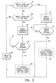
- the procedure of the invention begins at block 74 wherein the logic unit 72 (Fig. 2) determines whether gain is to be increased. This decision is based on angle and rate error signals generated by the combiner 66. If an increase of gain is required, the procedure passes to block 76 wherein there is a procedural step which applies with respect to all loop error signals and to the exclusion of all integral states of the control system 50. The step of block 76 is accomplished during initial setup of the control system 50, and there is determined a criteria for switching from low gain to high gain without significant perturbation of the actuator response. Thereupon, the procedure passes to block 78 wherein all loop error signals, but not the integral states, are examined to determine whether their values are within the bounds of the criteria of block 76. If the criteria is met, operation passes to branch point 80; and if the criteria is not met, operation is recycled back through a waiting loop 82 for further observation of the loop error signals at block 78.
- Blocks 86 and 98 are optional and are used only in the case wherein the control system uses integral states.
- operation passes directly from block 78 to block 84.
- block 86 is present, operation passes from block 78 via block 86 to block 84.
- block 86 is present, for each integral control state, there is a selection of the actuator which is most sensitive to the product of its high gain and the integral control state. The most sensitive actuator may be determined during the control system design process, and stored in a memory (not shown) of the logic unit 72. Thereupon, each integral control state is changed by a scaling of its amplitude.
- Such scaling may be performed outside the combiner 66 so as to output to the controller 58 a reduced value of the integral state.
- the reduction in the value of the integral control state is by a factor equal to the ratio of the low gain to the high gain.
- operation passes to block 88 where it is determined whether there is to be a switch from high gain to low gain. If it is determined at block 88 that there is to be no switching to low gain, then operation recycles back to block 74, in a waiting loop whereby the operation cycles between blocks 74 and 88 until a situation arises in the control of spacecraft attitude by the system 50 wherein it would be advantageous to switch gain.
- operation passes to block 90 wherein there is determined a criteria for switching from high gain to low gain without significant perturbation of the actuator response. Thereupon, the procedure passes to block 92 wherein all loop error signals, but not the integral states, are examined to determine whether their values are within the bounds of the criteria of block 90. If the criteria is met, operation passes to branch point 94; and if the criteria is not met, operation is recycled back through a waiting loop 96 for further observation of the measurement states at block 92.
- Blocks 86 and 98 are optional and only used in the case where the control system uses integral states.
- operation passes directly from block 92 to block 84.
- block 98 is present, operation passes from block 92 via block 98 to block 84.
- block 98 is present, for each integral control state, there is a selection of the actuator which is most sensitive to the product of its low gain and the integral control state. The most sensitive actuator may be determined during the control system design process, and stored in the memory of the logic unit 72. Thereupon, each integral control state is changed by a scaling of its amplitude.
- Such scaling may be performed outside the combiner 66 so as to output to the controller 58 an increased value of the integral state.
- the increase in the value of the integral control state is by a factor equal to the ratio of the high gain to the low gain.
- control system 50 can undergo a gain switching for improved performance without the disadvantage of a transient.
Abstract
Description
Claims (7)
- A method of operating a control system to inhibit formation of transients during a switching of a magnitude of the gains within the control system in order to drive a plant, the control system having a controller (58), the method comprising, applying a drive signal to actuation means (60) of the system for driving the plant (20), evaluating a difference between desired states of the plant and the estimates of the plant states to observe an occurrence of a magnitude of the difference which falls within a range of values satisfying a predetermined criteria, and switching a value of the gain during said occurrence.
- A method of operating a control system to inhibit formation of transients during a switching of a magnitude of the gains within the control system in order to drive a plant, the system having a controller (58) the method comprising, applying a drive signal to actuation means (60) of the system for driving the plant (20), distinguishing between estimates of the states of the plant and integral control states, wherein the integral control states are generated within the control system to maintain drive signal to the actuation means to counter disturbances on the plant, evaluating a portion of a controller input signal which portion is exclusive of the integral control states and is comprised of a difference between desired states of the plant and the estimates of the plant states to observe an occurrence of a magnitude of the difference which falls within a range of values satisfying a predetermined criteria, switching a value of the gain during said occurrence; and concurrently with said switching step, scaling an amplitude of the integral state by a factor inverse to a ratio of switched gain values.
- A method as claimed in Claim 2, wherein the control system has the controller (58) in a forward branch of the system and an estimator (64) in the feedback branch, the distinguishing step being performed at an input to the controller.
- A method as claimed in Claim 3, wherein the step of applying the drive signal to the actuation means (60) is accomplished via the controller.
- A method as claimed in Claim 4, further comprising a step of determining that a loop error signal of the control system meets said criteria prior to the gain switching step.
- A method as claimed in Claim 5, wherein said criteria is a criteria of minimal effect on the actuation means (60) and, for accomplishing said scaling step upon an increase of gain from a low gain to a high gain and said criteria-establishing step is accomplished by finding an actuator of a plurality of actuators of said actuation means which is most sensitive to a product of the high gain and the integral control state.
- A method as claimed in Claim 5, wherein for accomplishing said scaling step upon a decrease of gain from a high gain to a low gain, said criteria-establishing step is accomplished by finding an actuator of a plurality of actuators of the actuation means (60) which is most sensitive to a product of the low gain and the integral control state.
Applications Claiming Priority (2)
| Application Number | Priority Date | Filing Date | Title |
|---|---|---|---|
| US742854 | 1996-11-01 | ||
| US08/742,854 US5949675A (en) | 1996-11-01 | 1996-11-01 | Transient-free gain switching within error threshold |
Publications (2)
| Publication Number | Publication Date |
|---|---|
| EP0840186A1 true EP0840186A1 (en) | 1998-05-06 |
| EP0840186B1 EP0840186B1 (en) | 2000-03-22 |
Family
ID=24986518
Family Applications (1)
| Application Number | Title | Priority Date | Filing Date |
|---|---|---|---|
| EP97308682A Expired - Lifetime EP0840186B1 (en) | 1996-11-01 | 1997-10-30 | Transient-free gain switching |
Country Status (4)
| Country | Link |
|---|---|
| US (1) | US5949675A (en) |
| EP (1) | EP0840186B1 (en) |
| JP (1) | JPH10154001A (en) |
| DE (1) | DE69701501T2 (en) |
Families Citing this family (6)
| Publication number | Priority date | Publication date | Assignee | Title |
|---|---|---|---|---|
| JP3185738B2 (en) * | 1997-12-25 | 2001-07-11 | 日本電気株式会社 | Moving object state control apparatus and state control method |
| US6681159B2 (en) * | 2001-10-28 | 2004-01-20 | The Boeing Company | Spacecraft methods and structures with enhanced attitude control that facilitates gyroscope substitutions |
| US7729816B1 (en) * | 2006-01-23 | 2010-06-01 | Itt Manufacturing Enterprises, Inc. | System and method for correcting attitude estimation |
| US8352101B2 (en) * | 2009-12-22 | 2013-01-08 | The Boeing Company | Algorithm for simultaneous attitude maneuver and momentum dumping |
| US8918236B2 (en) | 2011-06-24 | 2014-12-23 | Honeywell International Inc. | Methods and systems for adjusting attitude using reaction wheels |
| US10338539B1 (en) * | 2018-02-19 | 2019-07-02 | Hamilton Sundstrand Corporation | Actuator control system with transient reduction after redundancy level changes |
Citations (3)
| Publication number | Priority date | Publication date | Assignee | Title |
|---|---|---|---|---|
| US4283670A (en) * | 1979-04-06 | 1981-08-11 | The United States Of America As Represented By The Secretary Of The Army | Automatic integrator control for transientless switching of _controller gains in manual tracking systems |
| US4752884A (en) * | 1985-07-18 | 1988-06-21 | Hughes Aircraft Company | Precision platform pointing controller for a dual-spin spacecraft |
| WO1993002885A1 (en) * | 1991-08-09 | 1993-02-18 | Ford Motor Company Limited | Speed control system with variable gains related to speed error |
Family Cites Families (8)
| Publication number | Priority date | Publication date | Assignee | Title |
|---|---|---|---|---|
| US5041833A (en) * | 1988-03-28 | 1991-08-20 | Stanford Telecommunications, Inc. | Precise satellite ranging and timing system using pseudo-noise bandwidth synthesis |
| JP3010583B2 (en) * | 1989-12-31 | 2000-02-21 | 株式会社エスジー | Multi-axis tuning control method |
| US5587896A (en) * | 1990-07-16 | 1996-12-24 | The Foxboro Company | Self-tuning controller |
| GB9017599D0 (en) * | 1990-08-10 | 1990-09-26 | Dowty Aerospace Gloucester | A propeller control system |
| US5562266A (en) * | 1992-10-29 | 1996-10-08 | Aerospatiale Societe Nationale Industrielle | Rate gyro calibration method and apparatus for a three-axis stabilized satellite |
| US5452869A (en) * | 1992-12-18 | 1995-09-26 | Hughes Aircraft Company | On-board three-axes attitude determination and control system |
| US5490057A (en) * | 1994-05-06 | 1996-02-06 | Vlt Corporation | Feedback control system having predictable open-loop gain |
| KR0162607B1 (en) * | 1995-12-20 | 1999-01-15 | 김광호 | Voice coil motor moving control circuit |
-
1996
- 1996-11-01 US US08/742,854 patent/US5949675A/en not_active Expired - Lifetime
-
1997
- 1997-10-30 EP EP97308682A patent/EP0840186B1/en not_active Expired - Lifetime
- 1997-10-30 DE DE69701501T patent/DE69701501T2/en not_active Expired - Fee Related
- 1997-11-04 JP JP9301869A patent/JPH10154001A/en active Pending
Patent Citations (3)
| Publication number | Priority date | Publication date | Assignee | Title |
|---|---|---|---|---|
| US4283670A (en) * | 1979-04-06 | 1981-08-11 | The United States Of America As Represented By The Secretary Of The Army | Automatic integrator control for transientless switching of _controller gains in manual tracking systems |
| US4752884A (en) * | 1985-07-18 | 1988-06-21 | Hughes Aircraft Company | Precision platform pointing controller for a dual-spin spacecraft |
| WO1993002885A1 (en) * | 1991-08-09 | 1993-02-18 | Ford Motor Company Limited | Speed control system with variable gains related to speed error |
Also Published As
| Publication number | Publication date |
|---|---|
| DE69701501T2 (en) | 2000-11-16 |
| EP0840186B1 (en) | 2000-03-22 |
| DE69701501D1 (en) | 2000-04-27 |
| JPH10154001A (en) | 1998-06-09 |
| US5949675A (en) | 1999-09-07 |
Similar Documents
| Publication | Publication Date | Title |
|---|---|---|
| US6292722B1 (en) | Magnetic torquer control with thruster augmentation | |
| JP3645038B2 (en) | Aircraft flight control equipment | |
| US5058836A (en) | Adaptive autopilot | |
| JPH04293698A (en) | Attitude controller for three axis stabilizing type artificial satellite | |
| US7996119B2 (en) | Method for determining the position of a spacecraft with the aid of a direction vector and an overall spin measurement | |
| EP0115401B1 (en) | Airspeed control for aircraft | |
| EP1678460B1 (en) | System and method with adaptive angle-of-attack autopilot | |
| US6000661A (en) | Autonomous spacecraft payload base motion estimation and correction | |
| US5949675A (en) | Transient-free gain switching within error threshold | |
| US5608634A (en) | Low noise spacecraft body rate sensing arrangement for attitude control | |
| US20030171855A1 (en) | Spacecraft methods and structures with enhanced attitude control that facilitates gyroscope substitutions | |
| WO1998016425A9 (en) | Feedback motion compensation for spacecraft payload | |
| US5875676A (en) | Non colocated rate sensing for control moment gyroscopes | |
| KR101408067B1 (en) | Method for improving geo-pointing performance of electro-optical device in aircraft | |
| US5787368A (en) | Spacecraft yaw control using only wheel speed measurements processed through a simple filter bank | |
| JP3206473B2 (en) | High stability attitude control system for satellite | |
| US5617316A (en) | Maintaining attitude error constant in Euler singularity protection | |
| EP0752367A1 (en) | Thruster control of yaw without yaw measurements | |
| EP1134640B1 (en) | Attitude control system for a spacecraft | |
| JPH0226301A (en) | Servocontroller | |
| US6196499B1 (en) | Lead compensated engines-only flight control system | |
| JPH10287299A (en) | Attitude control device of artificial satellite | |
| Moreno‐Valenzuela et al. | Dynamic positioning control of ships via relay observer design | |
| McEver et al. | Tracking filter algorithm for automatic video tracking | |
| JPH09113196A (en) | Control device for flying object |
Legal Events
| Date | Code | Title | Description |
|---|---|---|---|
| PUAI | Public reference made under article 153(3) epc to a published international application that has entered the european phase |
Free format text: ORIGINAL CODE: 0009012 |
|
| AK | Designated contracting states |
Kind code of ref document: A1 Designated state(s): DE FR GB IT |
|
| AX | Request for extension of the european patent |
Free format text: AL;LT;LV;RO;SI |
|
| 17P | Request for examination filed |
Effective date: 19980610 |
|
| 17Q | First examination report despatched |
Effective date: 19981026 |
|
| AKX | Designation fees paid |
Free format text: DE FR GB IT |
|
| RBV | Designated contracting states (corrected) |
Designated state(s): DE FR GB IT |
|
| GRAG | Despatch of communication of intention to grant |
Free format text: ORIGINAL CODE: EPIDOS AGRA |
|
| GRAG | Despatch of communication of intention to grant |
Free format text: ORIGINAL CODE: EPIDOS AGRA |
|
| GRAH | Despatch of communication of intention to grant a patent |
Free format text: ORIGINAL CODE: EPIDOS IGRA |
|
| GRAH | Despatch of communication of intention to grant a patent |
Free format text: ORIGINAL CODE: EPIDOS IGRA |
|
| GRAA | (expected) grant |
Free format text: ORIGINAL CODE: 0009210 |
|
| AK | Designated contracting states |
Kind code of ref document: B1 Designated state(s): DE FR GB IT |
|
| REF | Corresponds to: |
Ref document number: 69701501 Country of ref document: DE Date of ref document: 20000427 |
|
| ET | Fr: translation filed | ||
| ITF | It: translation for a ep patent filed |
Owner name: BUGNION S.P.A. |
|
| PLBE | No opposition filed within time limit |
Free format text: ORIGINAL CODE: 0009261 |
|
| STAA | Information on the status of an ep patent application or granted ep patent |
Free format text: STATUS: NO OPPOSITION FILED WITHIN TIME LIMIT |
|
| 26N | No opposition filed | ||
| REG | Reference to a national code |
Ref country code: GB Ref legal event code: IF02 |
|
| PGFP | Annual fee paid to national office [announced via postgrant information from national office to epo] |
Ref country code: FR Payment date: 20021002 Year of fee payment: 6 |
|
| PGFP | Annual fee paid to national office [announced via postgrant information from national office to epo] |
Ref country code: GB Payment date: 20021023 Year of fee payment: 6 |
|
| PGFP | Annual fee paid to national office [announced via postgrant information from national office to epo] |
Ref country code: DE Payment date: 20021031 Year of fee payment: 6 |
|
| PG25 | Lapsed in a contracting state [announced via postgrant information from national office to epo] |
Ref country code: GB Free format text: LAPSE BECAUSE OF NON-PAYMENT OF DUE FEES Effective date: 20031030 |
|
| PG25 | Lapsed in a contracting state [announced via postgrant information from national office to epo] |
Ref country code: DE Free format text: LAPSE BECAUSE OF NON-PAYMENT OF DUE FEES Effective date: 20040501 |
|
| GBPC | Gb: european patent ceased through non-payment of renewal fee |
Effective date: 20031030 |
|
| PG25 | Lapsed in a contracting state [announced via postgrant information from national office to epo] |
Ref country code: FR Free format text: LAPSE BECAUSE OF NON-PAYMENT OF DUE FEES Effective date: 20040630 |
|
| REG | Reference to a national code |
Ref country code: FR Ref legal event code: ST |
|
| PG25 | Lapsed in a contracting state [announced via postgrant information from national office to epo] |
Ref country code: IT Free format text: LAPSE BECAUSE OF NON-PAYMENT OF DUE FEES Effective date: 20051030 |