EP0839762A2 - Method and apparatus for scale prevention in producing deionized water - Google Patents
Method and apparatus for scale prevention in producing deionized water Download PDFInfo
- Publication number
- EP0839762A2 EP0839762A2 EP97118847A EP97118847A EP0839762A2 EP 0839762 A2 EP0839762 A2 EP 0839762A2 EP 97118847 A EP97118847 A EP 97118847A EP 97118847 A EP97118847 A EP 97118847A EP 0839762 A2 EP0839762 A2 EP 0839762A2
- Authority
- EP
- European Patent Office
- Prior art keywords
- compartment
- water
- housing
- electrodes
- anode
- Prior art date
- Legal status (The legal status is an assumption and is not a legal conclusion. Google has not performed a legal analysis and makes no representation as to the accuracy of the status listed.)
- Granted
Links
- XLYOFNOQVPJJNP-UHFFFAOYSA-N water Chemical compound O XLYOFNOQVPJJNP-UHFFFAOYSA-N 0.000 title claims abstract description 117
- 238000000034 method Methods 0.000 title claims abstract description 28
- 239000008367 deionised water Substances 0.000 title claims abstract description 26
- 229910021641 deionized water Inorganic materials 0.000 title claims abstract description 24
- 230000002265 prevention Effects 0.000 title 1
- 238000002242 deionisation method Methods 0.000 claims abstract description 36
- 238000005868 electrolysis reaction Methods 0.000 claims abstract description 35
- 230000002378 acidificating effect Effects 0.000 claims abstract description 31
- 230000001376 precipitating effect Effects 0.000 claims abstract description 12
- 239000012528 membrane Substances 0.000 claims description 31
- 238000007865 diluting Methods 0.000 claims description 29
- 238000005341 cation exchange Methods 0.000 claims description 28
- 239000003011 anion exchange membrane Substances 0.000 claims description 27
- 150000002500 ions Chemical class 0.000 claims description 22
- 239000003014 ion exchange membrane Substances 0.000 claims description 19
- OYPRJOBELJOOCE-UHFFFAOYSA-N Calcium Chemical compound [Ca] OYPRJOBELJOOCE-UHFFFAOYSA-N 0.000 claims description 8
- 239000011575 calcium Substances 0.000 claims description 8
- 229910052791 calcium Inorganic materials 0.000 claims description 8
- FYYHWMGAXLPEAU-UHFFFAOYSA-N Magnesium Chemical compound [Mg] FYYHWMGAXLPEAU-UHFFFAOYSA-N 0.000 claims description 7
- XUIMIQQOPSSXEZ-UHFFFAOYSA-N Silicon Chemical compound [Si] XUIMIQQOPSSXEZ-UHFFFAOYSA-N 0.000 claims description 7
- 239000011777 magnesium Substances 0.000 claims description 7
- 229910052749 magnesium Inorganic materials 0.000 claims description 7
- 229910052710 silicon Inorganic materials 0.000 claims description 7
- 239000010703 silicon Substances 0.000 claims description 7
- 238000007599 discharging Methods 0.000 claims description 5
- 230000007423 decrease Effects 0.000 abstract description 7
- 150000001768 cations Chemical class 0.000 description 6
- 238000000909 electrodialysis Methods 0.000 description 6
- 239000008399 tap water Substances 0.000 description 6
- 235000020679 tap water Nutrition 0.000 description 6
- 150000001450 anions Chemical class 0.000 description 5
- 239000003795 chemical substances by application Substances 0.000 description 5
- VYPSYNLAJGMNEJ-UHFFFAOYSA-N Silicium dioxide Chemical compound O=[Si]=O VYPSYNLAJGMNEJ-UHFFFAOYSA-N 0.000 description 4
- 239000000463 material Substances 0.000 description 4
- 229940043430 calcium compound Drugs 0.000 description 3
- 150000001674 calcium compounds Chemical class 0.000 description 3
- 150000002681 magnesium compounds Chemical class 0.000 description 3
- 239000012466 permeate Substances 0.000 description 3
- 150000003839 salts Chemical class 0.000 description 3
- VTYYLEPIZMXCLO-UHFFFAOYSA-L Calcium carbonate Chemical compound [Ca+2].[O-]C([O-])=O VTYYLEPIZMXCLO-UHFFFAOYSA-L 0.000 description 2
- BHPQYMZQTOCNFJ-UHFFFAOYSA-N Calcium cation Chemical compound [Ca+2] BHPQYMZQTOCNFJ-UHFFFAOYSA-N 0.000 description 2
- JLVVSXFLKOJNIY-UHFFFAOYSA-N Magnesium ion Chemical compound [Mg+2] JLVVSXFLKOJNIY-UHFFFAOYSA-N 0.000 description 2
- 229910001424 calcium ion Inorganic materials 0.000 description 2
- 230000000052 comparative effect Effects 0.000 description 2
- 230000003247 decreasing effect Effects 0.000 description 2
- 239000000835 fiber Substances 0.000 description 2
- -1 for example Chemical compound 0.000 description 2
- 229910001425 magnesium ion Inorganic materials 0.000 description 2
- BASFCYQUMIYNBI-UHFFFAOYSA-N platinum Chemical compound [Pt] BASFCYQUMIYNBI-UHFFFAOYSA-N 0.000 description 2
- 238000001223 reverse osmosis Methods 0.000 description 2
- 239000013535 sea water Substances 0.000 description 2
- 239000000377 silicon dioxide Substances 0.000 description 2
- BVKZGUZCCUSVTD-UHFFFAOYSA-L Carbonate Chemical compound [O-]C([O-])=O BVKZGUZCCUSVTD-UHFFFAOYSA-L 0.000 description 1
- ZAMOUSCENKQFHK-UHFFFAOYSA-N Chlorine atom Chemical compound [Cl] ZAMOUSCENKQFHK-UHFFFAOYSA-N 0.000 description 1
- DGAQECJNVWCQMB-PUAWFVPOSA-M Ilexoside XXIX Chemical compound C[C@@H]1CC[C@@]2(CC[C@@]3(C(=CC[C@H]4[C@]3(CC[C@@H]5[C@@]4(CC[C@@H](C5(C)C)OS(=O)(=O)[O-])C)C)[C@@H]2[C@]1(C)O)C)C(=O)O[C@H]6[C@@H]([C@H]([C@@H]([C@H](O6)CO)O)O)O.[Na+] DGAQECJNVWCQMB-PUAWFVPOSA-M 0.000 description 1
- QAOWNCQODCNURD-UHFFFAOYSA-L Sulfate Chemical compound [O-]S([O-])(=O)=O QAOWNCQODCNURD-UHFFFAOYSA-L 0.000 description 1
- RTAQQCXQSZGOHL-UHFFFAOYSA-N Titanium Chemical compound [Ti] RTAQQCXQSZGOHL-UHFFFAOYSA-N 0.000 description 1
- 229910000019 calcium carbonate Inorganic materials 0.000 description 1
- 239000013043 chemical agent Substances 0.000 description 1
- 239000000460 chlorine Substances 0.000 description 1
- 229910052801 chlorine Inorganic materials 0.000 description 1
- 239000011248 coating agent Substances 0.000 description 1
- 238000000576 coating method Methods 0.000 description 1
- 239000003792 electrolyte Substances 0.000 description 1
- 238000002474 experimental method Methods 0.000 description 1
- VTHJTEIRLNZDEV-UHFFFAOYSA-L magnesium dihydroxide Chemical compound [OH-].[OH-].[Mg+2] VTHJTEIRLNZDEV-UHFFFAOYSA-L 0.000 description 1
- 239000000347 magnesium hydroxide Substances 0.000 description 1
- 229910001862 magnesium hydroxide Inorganic materials 0.000 description 1
- 239000004745 nonwoven fabric Substances 0.000 description 1
- 229910052697 platinum Inorganic materials 0.000 description 1
- 238000010248 power generation Methods 0.000 description 1
- 239000002244 precipitate Substances 0.000 description 1
- 238000001556 precipitation Methods 0.000 description 1
- 235000012239 silicon dioxide Nutrition 0.000 description 1
- 239000011734 sodium Substances 0.000 description 1
- 229910052708 sodium Inorganic materials 0.000 description 1
- GCLGEJMYGQKIIW-UHFFFAOYSA-H sodium hexametaphosphate Chemical compound [Na]OP1(=O)OP(=O)(O[Na])OP(=O)(O[Na])OP(=O)(O[Na])OP(=O)(O[Na])OP(=O)(O[Na])O1 GCLGEJMYGQKIIW-UHFFFAOYSA-H 0.000 description 1
- 235000019982 sodium hexametaphosphate Nutrition 0.000 description 1
- 239000000126 substance Substances 0.000 description 1
- 230000009469 supplementation Effects 0.000 description 1
- 239000001577 tetrasodium phosphonato phosphate Substances 0.000 description 1
- 229910052719 titanium Inorganic materials 0.000 description 1
- 239000010936 titanium Substances 0.000 description 1
- 239000002351 wastewater Substances 0.000 description 1
Images

Classifications
-
- C—CHEMISTRY; METALLURGY
- C02—TREATMENT OF WATER, WASTE WATER, SEWAGE, OR SLUDGE
- C02F—TREATMENT OF WATER, WASTE WATER, SEWAGE, OR SLUDGE
- C02F5/00—Softening water; Preventing scale; Adding scale preventatives or scale removers to water, e.g. adding sequestering agents
- C02F5/08—Treatment of water with complexing chemicals or other solubilising agents for softening, scale prevention or scale removal, e.g. adding sequestering agents
-
- C—CHEMISTRY; METALLURGY
- C02—TREATMENT OF WATER, WASTE WATER, SEWAGE, OR SLUDGE
- C02F—TREATMENT OF WATER, WASTE WATER, SEWAGE, OR SLUDGE
- C02F1/00—Treatment of water, waste water, or sewage
- C02F1/46—Treatment of water, waste water, or sewage by electrochemical methods
- C02F1/469—Treatment of water, waste water, or sewage by electrochemical methods by electrochemical separation, e.g. by electro-osmosis, electrodialysis, electrophoresis
- C02F1/4693—Treatment of water, waste water, or sewage by electrochemical methods by electrochemical separation, e.g. by electro-osmosis, electrodialysis, electrophoresis electrodialysis
-
- B—PERFORMING OPERATIONS; TRANSPORTING
- B01—PHYSICAL OR CHEMICAL PROCESSES OR APPARATUS IN GENERAL
- B01D—SEPARATION
- B01D61/00—Processes of separation using semi-permeable membranes, e.g. dialysis, osmosis or ultrafiltration; Apparatus, accessories or auxiliary operations specially adapted therefor
- B01D61/42—Electrodialysis; Electro-osmosis ; Electro-ultrafiltration; Membrane capacitive deionization
- B01D61/44—Ion-selective electrodialysis
- B01D61/52—Accessories; Auxiliary operation
-
- C—CHEMISTRY; METALLURGY
- C02—TREATMENT OF WATER, WASTE WATER, SEWAGE, OR SLUDGE
- C02F—TREATMENT OF WATER, WASTE WATER, SEWAGE, OR SLUDGE
- C02F1/00—Treatment of water, waste water, or sewage
- C02F1/42—Treatment of water, waste water, or sewage by ion-exchange
-
- C—CHEMISTRY; METALLURGY
- C02—TREATMENT OF WATER, WASTE WATER, SEWAGE, OR SLUDGE
- C02F—TREATMENT OF WATER, WASTE WATER, SEWAGE, OR SLUDGE
- C02F1/00—Treatment of water, waste water, or sewage
- C02F1/46—Treatment of water, waste water, or sewage by electrochemical methods
- C02F1/4602—Treatment of water, waste water, or sewage by electrochemical methods for prevention or elimination of deposits
-
- C—CHEMISTRY; METALLURGY
- C02—TREATMENT OF WATER, WASTE WATER, SEWAGE, OR SLUDGE
- C02F—TREATMENT OF WATER, WASTE WATER, SEWAGE, OR SLUDGE
- C02F1/00—Treatment of water, waste water, or sewage
- C02F1/46—Treatment of water, waste water, or sewage by electrochemical methods
- C02F1/461—Treatment of water, waste water, or sewage by electrochemical methods by electrolysis
-
- C—CHEMISTRY; METALLURGY
- C02—TREATMENT OF WATER, WASTE WATER, SEWAGE, OR SLUDGE
- C02F—TREATMENT OF WATER, WASTE WATER, SEWAGE, OR SLUDGE
- C02F1/00—Treatment of water, waste water, or sewage
- C02F1/46—Treatment of water, waste water, or sewage by electrochemical methods
- C02F1/469—Treatment of water, waste water, or sewage by electrochemical methods by electrochemical separation, e.g. by electro-osmosis, electrodialysis, electrophoresis
- C02F1/4693—Treatment of water, waste water, or sewage by electrochemical methods by electrochemical separation, e.g. by electro-osmosis, electrodialysis, electrophoresis electrodialysis
- C02F1/4695—Treatment of water, waste water, or sewage by electrochemical methods by electrochemical separation, e.g. by electro-osmosis, electrodialysis, electrophoresis electrodialysis electrodeionisation
-
- C—CHEMISTRY; METALLURGY
- C02—TREATMENT OF WATER, WASTE WATER, SEWAGE, OR SLUDGE
- C02F—TREATMENT OF WATER, WASTE WATER, SEWAGE, OR SLUDGE
- C02F1/00—Treatment of water, waste water, or sewage
- C02F1/46—Treatment of water, waste water, or sewage by electrochemical methods
- C02F1/4604—Treatment of water, waste water, or sewage by electrochemical methods for desalination of seawater or brackish water
-
- C—CHEMISTRY; METALLURGY
- C02—TREATMENT OF WATER, WASTE WATER, SEWAGE, OR SLUDGE
- C02F—TREATMENT OF WATER, WASTE WATER, SEWAGE, OR SLUDGE
- C02F1/00—Treatment of water, waste water, or sewage
- C02F1/46—Treatment of water, waste water, or sewage by electrochemical methods
- C02F1/461—Treatment of water, waste water, or sewage by electrochemical methods by electrolysis
- C02F1/46104—Devices therefor; Their operating or servicing
- C02F1/4618—Devices therefor; Their operating or servicing for producing "ionised" acidic or basic water
-
- C—CHEMISTRY; METALLURGY
- C02—TREATMENT OF WATER, WASTE WATER, SEWAGE, OR SLUDGE
- C02F—TREATMENT OF WATER, WASTE WATER, SEWAGE, OR SLUDGE
- C02F2201/00—Apparatus for treatment of water, waste water or sewage
- C02F2201/46—Apparatus for electrochemical processes
- C02F2201/461—Electrolysis apparatus
- C02F2201/46105—Details relating to the electrolytic devices
- C02F2201/46115—Electrolytic cell with membranes or diaphragms
Definitions
- the present invention relates to a method and apparatus for preventing scale from precipitating in producing deionized water.
- the present application may be applied to removing ions in water in such areas as electric power, nuclear power generation, electronic industry, pharmaceutical industry, food industry, chemical industry and the like.
- Electrodialysis refers to a process for removing ions across a membrane from one solution to another under the influence of a direct current.
- a multicompartment electrodialysis has been proposed in which a plurality of anion exchange membranes alternated with a plurality of cation exchange membrane.
- the electrodialysis apparatus produces not only the deionized water in diluting compartments but also a concentrated water in concentrating compartments. Since the concentrated water has an increased concentration of salts, and scale tends to precipitate on surfaces of ion exchange membranes and an electrode, which are in contact with the concentrated water, and which define the concentrating compartments. As the scale precipitates, an electric resistance of the electrodialysis apparatus increases. In an extreme case, a substantial electric current does not flow through the electrodialysis apparatus, and further deionized water cannot be produced until the scale is removed.
- Such proposals include: adding an agent for preventing the scale, for example, sodium hexametaphosphate to a water to be treated; reversing the polarity of the electrodes; to set a low electric current density so as to decrease a difference in concentration between the deionized water in the diluting compartments and the concentrated water in the concentrating compartments; and to pretreat the water to be treated, for example, removing carbonate ions and adding a chemical agent for softening the water to be treated.
- an agent for preventing the scale for example, sodium hexametaphosphate
- reversing the polarity of the electrodes to set a low electric current density so as to decrease a difference in concentration between the deionized water in the diluting compartments and the concentrated water in the concentrating compartments
- to pretreat the water to be treated for example, removing carbonate ions and adding a chemical agent for softening the water to be treated.
- the addition of the agent for preventing the scale requires continued supplementation and control of the agent.
- the agent for preventing scale remains in waste water, and the agent needs to be removed therefrom, thereby increasing labor and costs.
- the reversal of the polarity of the electrodes exchanges the diluting compartments and the concentrating compartments, thereby decreasing efficiency to remove ions.
- To set the lower electric current density requires an increased area in the ion exchange membranes for an amount of water to be treated, thereby enlarging the apparatus and increasing costs.
- the pretreatment enlarges the apparatus and increase the costs.
- a method for preventing scale from precipitating in producing deionized water comprising the steps of: providing a continuous deionization unit having: a first housing; a pair of first electrodes serving as an anode and a cathode; a plurality of anion exchange membranes being disposed between the pair of the first electrodes in the first housing; and a plurality of cation exchange membranes being disposed between the pair of the first electrodes in the first housing and alternated with the anion exchange membranes; wherein the first housing, the anion exchange membranes and the cation exchange membranes define at least one diluting compartment and at least one concentrating compartment being alternated with each other; providing an electrolysis unit having: a second housing; a pair of second electrodes serving as an anode and a cathode; wherein the second housing and the ion exchange membrane define an anode compartment and a cathode compartment; introducing water into the anode compartment and the cathode compartment in
- the acidic water has pH ranging from about 2 to about 5. Further preferably, the acidic water has pH ranging from about 2 to about 4.
- the method may have the steps of introducing an ion-containing water into a continuous deionization unit; applying an electric direct current to the pair of the first electrodes in the continuous deionization unit so as to produce deionized water in the diluting compartment and a concentrated water in the concentrating compartment; and discharging the deionized water from the diluting compartment.
- the method may further have the step of introducing the concentrated water in the concentrating compartment into at least one of the anode compartment and the cathode compartment in the electrolysis unit.
- the ion-containing water has a calcium concentration ranging from 0.01 to 100 mg per liter, a magnesium concentration ranging from 0.01 to 80 mg per liter, and a silicon content of up to 40 mg per liter. Further preferably, the ion containing water has a calcium concentration ranging from 0.01 to 40 mg per liter, a magnesium concentration ranging from 0.01 to 30 mg per liter, and a silicon content of up to 30 mg per liter.
- an apparatus for producing deionized water comprising: a continuous deionization unit having: a first housing: a pair of first electrodes serving as an anode and a cathode; a plurality of anion exchange membranes being disposed between the pair of the first electrodes in the first housing; and a plurality of cation exchange membranes being disposed between the pair of the first electrodes in the first housing and alternated with the anion exchange membranes; wherein the first housing, the anion exchange membranes and the cation exchange membranes define at least one diluting compartment and at least one concentrating compartment being alternated each other; and an electrolysis unit having: a second housing; a pair of second electrodes serving as an anode and a cathode; an ion exchange membrane being disposed in the second housing and separating one of the second electrodes from the other second electrodes; wherein the second housing and the ion exchange membrane define a cathode compartment and an anode compartment, and
- the apparatus may further comprise a first manifold connecting the anode compartment in the electrolysis unit to the concentrating compartment in the continuous deionization unit.
- the concentrating compartment in the continuous deionization unit communicates with at least one of the anode compartment and the cathode compartment in the electrolyses unit.
- the apparatus may further comprise a second manifold connecting the concentrating compartment in the continuous deionization unit to at least one of the anode compartment and the cathode compartment in the electrolysis unit.
- the ion exchange membrane comprises a cation exchange membrane.
- the apparatus may further comprise an electric source for applying an electric direct current to the pair of the first electrodes and the pair of the second electrodes.
- an acidic water produced in the anode compartment is introduced into the concentrating compartment so as to decrease pH of the concentrated water therein, thereby preventing a scale from precipitating.
- Fig. 1 is a schematic view of one embodiment in accordance with the present invention.
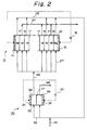
- Fig. 2 is a schematic view of another embodiment in accordance with the present invention.
- a continuous deionization apparatus in accordance with the present invention has a continuous deionization unit 10 and an electrolysis unit 30.
- the continuous deionization unit 10 has a housing 12 and a pair of electrodes 14, 15 serving as an anode and a cathode, respectively.
- the electrodes may have a plate shape, although the configuration of the electrodes is not limited. Materials for the electrode are not limited as long as the materials are electrically conductive.
- An electric source 13 is provided so as to supply an electric direct current to the pair of the electrodes 14, 15.
- the electrodes 14, 15 face electrode compartments 14a, 15a, respectively, in which water can be charged. In the electrode compartments 14a, 15a, ion concentrations of water increase and, in this sense, the electrode compartments can be regarded as the concentrating compartments.
- a plurality of cation exchange membranes 16 are alternated with a plurality of anion exchange membranes 17 between the pair of the electrodes 14, 15 in the housing 12.
- the housing 12, the cation exchange membranes 16 and the anion exchange membranes 17 define at least one diluting compartment 18 and at least one concentrating compartment 19 being alternated with each other.
- a cation exchanger and/or an anion exchanger fill the diluting compartments 18 for removing ions further, thereby producing deionised water having a further decreased ion concentration.
- the diluting compartments 18 are connected to a supply line 22 for supplying a water to be treated and to a discharge line 24 for discharging deionized water.
- the concentrating compartments 19 are connected to a discharge line 25 for discharging a concentrated water.
- the electrolysis unit 30 has a housing 32 and a pair of electrodes 34, 35 serving as an anode and a cathode.
- An electric source 33 is provided so as to supply an electric direct current to the pair of the electrodes 34, 35.
- the electric source 33 may be different from the electric source 14.
- a single electric source may be shared by way of a serial or parallel connection.
- An ion exchange membrane 36 is disposed in the housing 32 and separates the electrode 34 from the electrode 35.
- the housing 32 and the ion exchange membrane 36 define an anode compartment 38 and a cathode compartment 39.
- the ion exchange membrane 36 comprises the cation exchange membrane so as to further remove a scale component such as a calcium ion, magnesium ion from an acidic water 38 produced in the anode compartment 38.
- the anode compartment 38 and the cathode compartment 39 are connected to a supply line 42 for introducing a water thereinto.
- the supply line may be connected to a water supply line 44 for supplying, for example, tap water.
- the discharge line 25 of the continuous deionizing unit 10 is connected to a supply line 42 of the electrolysis unit 10 for introducing the concentrated water produced in the concentrating compartments 19 of the continuous deionizing unit 10 into the anode compartment 38 and the cathode compartment 39 of the electrolysis unit 30 so as to recycle the concentrated water and provide a sufficient conductivity in the water of the anode and cathode compartments 38, 39.
- the anode compartment 38 of the electrolysis unit 30 communicates with the concentrating compartments 19 in the continuous deionization unit 10 for introducing an acidic water produced in the anode compartment 38 into the concentrating compartment 19 so as to decrease pH of the concentrated water therein, thereby preventing scale from precipitating.
- a manifold 26, serving as the supply line to the concentrating compartments 19, connects the anode compartment 38 in the electrolysis unit 30 to the concentrating compartments 19 in the continuous deionization unit 10.
- the electric source 13 applies a direct current to the anode 14 and the cathode 15, and cations in water tend to move toward the negatively charged cathode 15.
- the cations are able to permeate the cation-exchange membranes 16 but not the anion-exchange membranes 17.
- anions tend to move toward the positively charged anode 14.
- the anions are able to permeate the anion-exchange membranes 17 but not the cation-exchange membrane 18.
- the water in the diluting compartments 18 is depleted of ions, thereby producing a deionized water.
- the water in the concentrating compartments 10 is enriched by ions, thereby producing a concentrated water. Since the concentrated water has an increased salt concentration, a scale tends to precipitate on surfaces of ion exchange membranes that face the concentrating compartments 19.
- the deionized water in the diluting compartments 18 is discharged therefrom through the discharge line 24 whereas the concentrated water in the concentrating compartments 19 is discharged therefrom through the discharge line 25.
- Water preferably a water containing an electrolyte
- the concentrated water produced in the concentrating compartments 19 may be introduced into at least one of the anode compartments 38 and the cathode compartments 39 of the electrolysis unit 30 so as to recycle the concentrated water and provide a sufficient conductivity in the water of the anode and cathode compartments 38, 39.
- the electric source 33 applies a direct current to the anode 34 and the cathode 35 so as to electrolyze the water in the anode compartment 38 and the cathode compartment 39 of the electrolysis unit 30.
- cations and anions permeate the ion exchange membrane 36 so as to produce an acidic water in the anode compartment 38 and an alkaline water in the cathode compartment.
- the acidic water produced in the anode compartment 38 has pH ranging from about 2 to about 5. Further preferably, the acidic water produced in the anode compartment 38 has pH ranging from about 2 to about 4.
- the acidic water has pH larger than 5, a large quantity of the acidic water is required to decrease pH of the concentrated water in the concentrating compartments 19.
- the acidic water has pH smaller than 2, special materials withstanding acidity are necessary for the housing 32, the discharge line 46 and the like, which are in contact with the acidic water.
- the cost for producing the acidic water by electrolysis increases.
- the acidic water thus produced is introduced into the concentrating compartments 19 in the continuous deionisation unit 10 by means of, for example, the discharge line 46 and the supply line 26.
- the acidic water decreases pH of the concentrated water in the concentrating compartments 19, thereby preventing a scale from precipitating therein.
- the alkaline water in the cathode compartment 39 is discharged through the discharge line 48. Contrary to related art of reversing the polarity of the deionizing unit 10, the diluting compartments and the concentrating compartments do not exchange.
- Fig. 2 shows another embodiment of the present invention.
- the same reference numerals in Fig. 2 refer to the same elements as those of Fig. 1.
- a cation exchange membrane 37 is used in the electrolysis unit 30 so as to produce an acidic water being free of cations such as calcium ion, magnesium ion and the like. Calcium compounds and magnesium compounds are major contributors in the scale. Therefore, the acidic water free of such scale components is introduced into the diluting compartments 18 and the concentrating compartments 19 so as to further prevent scale from precipitating.
- Scale precipitated generally contain calcium compounds, for example, calcium carbonate; magnesium compounds, for example, magnesium hydroxide; and gel materials, for example, silicon dioxide.
- the present invention may be applied to tap water, and water obtained by reverse osmosis membrane.
- sea water may be treated by the method and apparatus of the present invention
- the sea water preferably be treated by, for example, the reverse osmosis membrane so as to decrease concentrations of salts, and then the resulting diluted water is further treated by the method and the apparatus of the present invention.
- the water that is introduced into the diluting compartments 18 may contain ions and may have a calcium concentration ranging from 0.01 to 100 mg per liter, preferably from 0.01 to 40 mg per liter, and a magnesium concentration ranging from 0.01 to 80 mg per liter, preferably 0.01 to 30 mg per liter.
- the ion containing water may have conductivity up to 1000 ⁇ S/cm, preferably up to 300 ⁇ S/cm.
- the ion containing water may have a silicon content of up to 40 mg per liter, preferably up to 30 mg per liter.
- the cation exchange membranes and the anion exchange membranes are not limited.
- the continuos deionizing apparatus of Fig. 1 is used. However, contrary to Fig. 1, the discharge line 24 was not connected to the supply line 42.
- the apparatus had two diluting compartments 18, one concentrating compartment 19, and two electrode compartments 14a, 15a.
- Nonwoven fabric having a trade name under EPIX FILTER produced by Ebara Corporation, Japan comprising a cation exchanger in fiber configuration and anion exchanger in fiber configuration filled both of the diluting compartments 18.
- Each of the electrodes 14, 15 had a plate consisting essentially of titanium and a platinum coating electroplated onto one of the major surface of the plate.
- Cation exchange membranes having a trade name under CMX from Tokuyama Inc.(Japan) and the anion exchange membrane having a trade name under AMX from Tokuyama Inc.(Japan) were used.
- a tap water having conductivity of about 200 ⁇ S/cm was introduced into the diluting compartment 18 through the supply line 22 at the rate of 30 liters per hour.
- the tap water had a calcium content of 20 milligram per liter, a sodium content of 9 milligram per liter, chlorine content of 15 milligram per liter, a sulfate content of 20 milligram per liter, a silica content of 20 milligram per liter.
- the tap water is introduced into the anode compartment 38 and the cathode compartment 39 of the electrolysis unit 30 through the supply line 44 at a flow rate LV of 0.1 to 3.0 centimeter per second.
- An acidic water produced in the anode Compartment 38 was introduced into the concentrating compartment 19 and the electrode compartments 14a, 15a at a rate of 10 liters per hour. 0.75 amperes of electric direct current was applied to the continuous deionizing unit 10 while 1.0 ampere of electric direct current was applied to the electrolysis unit 30. Under these conditions, the acidic water had pH of about 3.
- the same experiment was carried out using the apparatus having the continuous deionization unit 10 but not having the electrolysis unit 30.
- the tap water was introduced into not only the diluting compartment 18 but also the concentrating compartment 19 and the electrode compartments 14a, 15a.
- the invention relates to a method producing deionized water comprising the steps of providing a continuous deionization unit and a plurality of cation exchange membranes.
Landscapes
- Chemical & Material Sciences (AREA)
- Chemical Kinetics & Catalysis (AREA)
- Water Supply & Treatment (AREA)
- Engineering & Computer Science (AREA)
- Life Sciences & Earth Sciences (AREA)
- Hydrology & Water Resources (AREA)
- Environmental & Geological Engineering (AREA)
- Organic Chemistry (AREA)
- General Chemical & Material Sciences (AREA)
- Electrochemistry (AREA)
- Health & Medical Sciences (AREA)
- Analytical Chemistry (AREA)
- Molecular Biology (AREA)
- Urology & Nephrology (AREA)
- Water Treatment By Electricity Or Magnetism (AREA)
- Separation Using Semi-Permeable Membranes (AREA)
Abstract
Description
- The present invention relates to a method and apparatus for preventing scale from precipitating in producing deionized water. The present application may be applied to removing ions in water in such areas as electric power, nuclear power generation, electronic industry, pharmaceutical industry, food industry, chemical industry and the like.
- An electrodialysis apparatus has been used to produce deionized water. Electrodialysis refers to a process for removing ions across a membrane from one solution to another under the influence of a direct current. A multicompartment electrodialysis has been proposed in which a plurality of anion exchange membranes alternated with a plurality of cation exchange membrane.
- The electrodialysis apparatus produces not only the deionized water in diluting compartments but also a concentrated water in concentrating compartments. Since the concentrated water has an increased concentration of salts, and scale tends to precipitate on surfaces of ion exchange membranes and an electrode, which are in contact with the concentrated water, and which define the concentrating compartments. As the scale precipitates, an electric resistance of the electrodialysis apparatus increases. In an extreme case, a substantial electric current does not flow through the electrodialysis apparatus, and further deionized water cannot be produced until the scale is removed.
- It has been proposed to prevent scale from precipitating. Such proposals include: adding an agent for preventing the scale, for example, sodium hexametaphosphate to a water to be treated; reversing the polarity of the electrodes; to set a low electric current density so as to decrease a difference in concentration between the deionized water in the diluting compartments and the concentrated water in the concentrating compartments; and to pretreat the water to be treated, for example, removing carbonate ions and adding a chemical agent for softening the water to be treated.
- However, the addition of the agent for preventing the scale requires continued supplementation and control of the agent. Moreover, the agent for preventing scale remains in waste water, and the agent needs to be removed therefrom, thereby increasing labor and costs. The reversal of the polarity of the electrodes exchanges the diluting compartments and the concentrating compartments, thereby decreasing efficiency to remove ions. To set the lower electric current density requires an increased area in the ion exchange membranes for an amount of water to be treated, thereby enlarging the apparatus and increasing costs. The pretreatment enlarges the apparatus and increase the costs.
- It is an object of the present invention to solve the aforementioned problems and to provide a novel method and an apparatus for preventing scale from precipitating in producing deionised water.
- According to one aspect of the present invention, there is provided a method for preventing scale from precipitating in producing deionized water comprising the steps of: providing a continuous deionization unit having: a first housing; a pair of first electrodes serving as an anode and a cathode; a plurality of anion exchange membranes being disposed between the pair of the first electrodes in the first housing; and a plurality of cation exchange membranes being disposed between the pair of the first electrodes in the first housing and alternated with the anion exchange membranes; wherein the first housing, the anion exchange membranes and the cation exchange membranes define at least one diluting compartment and at least one concentrating compartment being alternated with each other; providing an electrolysis unit having: a second housing; a pair of second electrodes serving as an anode and a cathode; wherein the second housing and the ion exchange membrane define an anode compartment and a cathode compartment; introducing water into the anode compartment and the cathode compartment in the electrolysis unit; applying an electric direct current to the pair of the second electrodes so as to produce acidic water in the anode compartment; and introducing the acidic water into the concentrating compartment in the continuous deionization unit.
- Preferably, the acidic water has pH ranging from about 2 to about 5. Further preferably, the acidic water has pH ranging from about 2 to about 4.
- In the present invention, the method may have the steps of introducing an ion-containing water into a continuous deionization unit; applying an electric direct current to the pair of the first electrodes in the continuous deionization unit so as to produce deionized water in the diluting compartment and a concentrated water in the concentrating compartment; and discharging the deionized water from the diluting compartment.
- Preferably, the method may further have the step of introducing the concentrated water in the concentrating compartment into at least one of the anode compartment and the cathode compartment in the electrolysis unit.
- Preferably, the ion-containing water has a calcium concentration ranging from 0.01 to 100 mg per liter, a magnesium concentration ranging from 0.01 to 80 mg per liter, and a silicon content of up to 40 mg per liter. Further preferably, the ion containing water has a calcium concentration ranging from 0.01 to 40 mg per liter, a magnesium concentration ranging from 0.01 to 30 mg per liter, and a silicon content of up to 30 mg per liter.
- According to another aspect of the present invention, there is provided an apparatus for producing deionized water comprising: a continuous deionization unit having: a first housing: a pair of first electrodes serving as an anode and a cathode; a plurality of anion exchange membranes being disposed between the pair of the first electrodes in the first housing; and a plurality of cation exchange membranes being disposed between the pair of the first electrodes in the first housing and alternated with the anion exchange membranes; wherein the first housing, the anion exchange membranes and the cation exchange membranes define at least one diluting compartment and at least one concentrating compartment being alternated each other; and an electrolysis unit having: a second housing; a pair of second electrodes serving as an anode and a cathode; an ion exchange membrane being disposed in the second housing and separating one of the second electrodes from the other second electrodes; wherein the second housing and the ion exchange membrane define a cathode compartment and an anode compartment, and the anode compartment communicates with the concentrating compartment in the continuous deionization unit.
- In the present invention, the apparatus may further comprise a first manifold connecting the anode compartment in the electrolysis unit to the concentrating compartment in the continuous deionization unit.
- Preferably, the concentrating compartment in the continuous deionization unit communicates with at least one of the anode compartment and the cathode compartment in the electrolyses unit.
- The apparatus may further comprise a second manifold connecting the concentrating compartment in the continuous deionization unit to at least one of the anode compartment and the cathode compartment in the electrolysis unit.
- Preferably, the ion exchange membrane comprises a cation exchange membrane.
- The apparatus may further comprise an electric source for applying an electric direct current to the pair of the first electrodes and the pair of the second electrodes.
- In the present invention, an acidic water produced in the anode compartment is introduced into the concentrating compartment so as to decrease pH of the concentrated water therein, thereby preventing a scale from precipitating.
- Fig. 1 is a schematic view of one embodiment in accordance with the present invention.
- Fig. 2 is a schematic view of another embodiment in accordance with the present invention.
- In Fig. 1, a continuous deionization apparatus in accordance with the present invention has a
continuous deionization unit 10 and anelectrolysis unit 30. Thecontinuous deionization unit 10 has ahousing 12 and a pair ofelectrodes electric source 13 is provided so as to supply an electric direct current to the pair of theelectrodes electrodes face electrode compartments electrode compartments - A plurality of
cation exchange membranes 16 are alternated with a plurality ofanion exchange membranes 17 between the pair of theelectrodes housing 12. Thehousing 12, thecation exchange membranes 16 and theanion exchange membranes 17 define at least onediluting compartment 18 and at least one concentratingcompartment 19 being alternated with each other. - Preferably, a cation exchanger and/or an anion exchanger fill the
diluting compartments 18 for removing ions further, thereby producing deionised water having a further decreased ion concentration. - The
diluting compartments 18 are connected to asupply line 22 for supplying a water to be treated and to adischarge line 24 for discharging deionized water. On the other hand, the concentratingcompartments 19 are connected to adischarge line 25 for discharging a concentrated water. - The
electrolysis unit 30 has ahousing 32 and a pair ofelectrodes electric source 33 is provided so as to supply an electric direct current to the pair of theelectrodes electric source 33 may be different from theelectric source 14. Alternatively, a single electric source may be shared by way of a serial or parallel connection. - An
ion exchange membrane 36 is disposed in thehousing 32 and separates theelectrode 34 from theelectrode 35. Thehousing 32 and theion exchange membrane 36 define ananode compartment 38 and acathode compartment 39. - In the present invention, preferably, the
ion exchange membrane 36 comprises the cation exchange membrane so as to further remove a scale component such as a calcium ion, magnesium ion from anacidic water 38 produced in theanode compartment 38. - The
anode compartment 38 and thecathode compartment 39 are connected to asupply line 42 for introducing a water thereinto. The supply line may be connected to awater supply line 44 for supplying, for example, tap water. - As shown in Fig. 1, preferably, the
discharge line 25 of the continuous deionizingunit 10 is connected to asupply line 42 of theelectrolysis unit 10 for introducing the concentrated water produced in the concentratingcompartments 19 of the continuous deionizingunit 10 into theanode compartment 38 and thecathode compartment 39 of theelectrolysis unit 30 so as to recycle the concentrated water and provide a sufficient conductivity in the water of the anode andcathode compartments - In the present invention, the
anode compartment 38 of theelectrolysis unit 30 communicates with the concentratingcompartments 19 in thecontinuous deionization unit 10 for introducing an acidic water produced in theanode compartment 38 into the concentratingcompartment 19 so as to decrease pH of the concentrated water therein, thereby preventing scale from precipitating. In Fig. 1, amanifold 26, serving as the supply line to the concentratingcompartments 19, connects theanode compartment 38 in theelectrolysis unit 30 to the concentratingcompartments 19 in thecontinuous deionization unit 10. - A method of the present invention is explained hereinafter.
- The
electric source 13 applies a direct current to theanode 14 and thecathode 15, and cations in water tend to move toward the negativelycharged cathode 15. The cations are able to permeate the cation-exchange membranes 16 but not the anion-exchange membranes 17. On the other hand, anions tend to move toward the positivelycharged anode 14. The anions are able to permeate the anion-exchange membranes 17 but not the cation-exchange membrane 18. As a result, the water in the dilutingcompartments 18 is depleted of ions, thereby producing a deionized water. On the other hand, the water in the concentratingcompartments 10 is enriched by ions, thereby producing a concentrated water. Since the concentrated water has an increased salt concentration, a scale tends to precipitate on surfaces of ion exchange membranes that face theconcentrating compartments 19. - The deionized water in the diluting compartments 18 is discharged therefrom through the
discharge line 24 whereas the concentrated water in the concentratingcompartments 19 is discharged therefrom through thedischarge line 25. - Water, preferably a water containing an electrolyte, is introduced into the
anode compartment 38 and thecathode compartment 39 of theelectrolysis unit 30. For example, the concentrated water produced in the concentratingcompartments 19 may be introduced into at least one of the anode compartments 38 and the cathode compartments 39 of theelectrolysis unit 30 so as to recycle the concentrated water and provide a sufficient conductivity in the water of the anode andcathode compartments - The
electric source 33 applies a direct current to theanode 34 and thecathode 35 so as to electrolyze the water in theanode compartment 38 and thecathode compartment 39 of theelectrolysis unit 30. As a result, cations and anions permeate theion exchange membrane 36 so as to produce an acidic water in theanode compartment 38 and an alkaline water in the cathode compartment. 39. - In the present invention, preferably, the acidic water produced in the
anode compartment 38 has pH ranging from about 2 to about 5. Further preferably, the acidic water produced in theanode compartment 38 has pH ranging from about 2 to about 4. When the acidic water has pH larger than 5, a large quantity of the acidic water is required to decrease pH of the concentrated water in the concentrating compartments 19. On the other hand, when the acidic water has pH smaller than 2, special materials withstanding acidity are necessary for thehousing 32, thedischarge line 46 and the like, which are in contact with the acidic water. Moreover, the cost for producing the acidic water by electrolysis increases. - The acidic water thus produced is introduced into the concentrating
compartments 19 in thecontinuous deionisation unit 10 by means of, for example, thedischarge line 46 and thesupply line 26. The acidic water decreases pH of the concentrated water in the concentratingcompartments 19, thereby preventing a scale from precipitating therein. The alkaline water in thecathode compartment 39 is discharged through thedischarge line 48. Contrary to related art of reversing the polarity of the deionizingunit 10, the diluting compartments and the concentrating compartments do not exchange. - Fig. 2 shows another embodiment of the present invention. The same reference numerals in Fig. 2 refer to the same elements as those of Fig. 1.
- In Fig. 2, only the acidic water produced in the
anode compartment 38 of theelectrolysis unit 30 is introduced into the diluting compartments 18 and the concentratingcompartments 19 of thecontinuous deionizing unit 10 by means of, for example, thedischarge line 46 and thesupply line 27 for introducing water to the diluting compartments 18 and the concentrating compartments 19. - In this embodiment, a
cation exchange membrane 37 is used in theelectrolysis unit 30 so as to produce an acidic water being free of cations such as calcium ion, magnesium ion and the like. Calcium compounds and magnesium compounds are major contributors in the scale. Therefore, the acidic water free of such scale components is introduced into the diluting compartments 18 and the concentratingcompartments 19 so as to further prevent scale from precipitating. - Scale precipitated generally contain calcium compounds, for example, calcium carbonate; magnesium compounds, for example, magnesium hydroxide; and gel materials, for example, silicon dioxide.
- The present invention may be applied to tap water, and water obtained by reverse osmosis membrane. Although sea water may be treated by the method and apparatus of the present invention, the sea water preferably be treated by, for example, the reverse osmosis membrane so as to decrease concentrations of salts, and then the resulting diluted water is further treated by the method and the apparatus of the present invention. On the other hand, it might be unnecessary to apply the method and the apparatus of the present invention to an ion exchanged water, which is free of ions and such scale components as the calcium compounds and the magnesium compounds.
- In view of the foregoing, the water that is introduced into the diluting compartments 18 may contain ions and may have a calcium concentration ranging from 0.01 to 100 mg per liter, preferably from 0.01 to 40 mg per liter, and a magnesium concentration ranging from 0.01 to 80 mg per liter, preferably 0.01 to 30 mg per liter.
- The ion containing water may have conductivity up to 1000 µS/cm, preferably up to 300 µS/cm. The ion containing water may have a silicon content of up to 40 mg per liter, preferably up to 30 mg per liter.
- In the present invention, the cation exchange membranes and the anion exchange membranes are not limited.
- The present invention is explained by way of examples hereinafter. The examples are illustrative and should not be interpreted as limiting the scope of the present invention.
- The continuos deionizing apparatus of Fig. 1 is used. However, contrary to Fig. 1, the
discharge line 24 was not connected to thesupply line 42. The apparatus had two dilutingcompartments 18, one concentratingcompartment 19, and twoelectrode compartments electrodes - A tap water having conductivity of about 200 µS/cm was introduced into the diluting
compartment 18 through thesupply line 22 at the rate of 30 liters per hour. The tap water had a calcium content of 20 milligram per liter, a sodium content of 9 milligram per liter, chlorine content of 15 milligram per liter, a sulfate content of 20 milligram per liter, a silica content of 20 milligram per liter. The tap water is introduced into theanode compartment 38 and thecathode compartment 39 of theelectrolysis unit 30 through thesupply line 44 at a flow rate LV of 0.1 to 3.0 centimeter per second. - An acidic water produced in the
anode Compartment 38 was introduced into the concentratingcompartment 19 and theelectrode compartments continuous deionizing unit 10 while 1.0 ampere of electric direct current was applied to theelectrolysis unit 30. Under these conditions, the acidic water had pH of about 3. - As a comparative example, the same experiment was carried out using the apparatus having the
continuous deionization unit 10 but not having theelectrolysis unit 30. In the apparatus, the tap water was introduced into not only the dilutingcompartment 18 but also the concentratingcompartment 19 and theelectrode compartments - Even after operating the apparatus in accordance with the present invention in a period of 200 hours, a scale precipitation onto surfaces of the
cation exchange membranes 16,anion exchange membranes 17 and theelectrodes cation exchange membranes 16,anion exchange membranes 17 and theelectrodes - It should be noted that the objects and advantages of the invention may be attained by means of any compatible combination(s) particularly pointed out in the items of the following summary of the invention and the appended claims.
-
- 1. A method for preventing scale from precipitating in producing deionized water comprising the steps of:
- providing a continuous deionization unit having: a first housing; a pair of first electrodes serving as an anode and a cathode; a plurality of anion exchange membranes being disposed between the pair of the first electrodes in the first housing; and a plurality of cation exchange membranes being disposed between the pair of the first electrodes in the first housing and alternated with the anion exchange membranes; wherein the first housing, the anion exchange membranes and the cation exchange membranes define at least one diluting compartment and at least one concentrating compartment being alternated with each other;
- providing an electrolysis unit having: a second housing; a pair of second electrodes serving as an anode and a cathode; wherein the second housing and the ion exchange membrane define an anode compartment and a cathode compartment;
- introducing water into the anode compartment and the cathode compartment in the electrolysis unit;
- applying an electric direct current to the pair of the second electrodes so as to produce an acidic water in the anode compartment; and
- introducing the acidic water into the concentrating compartment in the continuous deionization unit.
- 2. A method wherein the acidic water has pH ranging from about 2 to about 5.
- 3. A method wherein the acidic water has pH ranging from about 2 to about 4.
- 4. A method further comprising the steps of introducing an ion-containing water into a continuous deionization unit;
- applying an electric direct current to the pair of the first electrodes in the continuous deionization unit so as to produce deionized water in the diluting compartment and a concentrated water in the concentrating compartment; and
- discharging the deionized water from the diluting compartment.
- 5. A method further comprising the step of introducing the concentrated water in the concentrating compartment into at least one of the anode compartment and the cathode compartment in the electrolysis unit.
- 6. A method wherein the ion-containing water has a calcium concentration ranging from 0.01 to 100 mg per liter, a magnesium concentration ranging from 0.01 to 80 mg per liter, and a silicon content of up to 40 mg per liter.
- 7. A method wherein the ion-containing water has a calcium concentration ranging from 0.01 to 40 mg per liter, a magnesium concentration ranging from 0.01 to 30 mg per liter, and a silicon content of up to 30 mg per liter.
- 8. An apparatus for producing deionized water comprising:
- a continuous deionization unit having:
- a first housing:
- a pair of first electrodes serving as an anode and a cathode;
- a plurality of anion exchange membranes being disposed between the pair of the first electrodes in the first housing; and
- a plurality of cation exchange membranes being disposed between the pair of the first electrodes in the first housing and alternated with the anion exchange membranes;
wherein the first housing, the anion exchange membranes and the cation exchange membranes define at least one diluting compartment and at least one concentrating compartment being alternated each other; and
- an electrolysis unit having:
- a second housing;
- a pair of second electrodes serving as an anode and a cathode;
- an ion exchange membrane being disposed in the second housing and separating one of the second
wherein the second housing and the ion exchange membrane define a cathode compartment and an anode compartment, and the anode compartment communicates with the concentrating compartment in the continuous deionization unit.
- a continuous deionization unit having:
- 9. An apparatus further comprising a first manifold connecting the anode compartment in the electrolysis unit to the concentrating compartment in the continuous deionization unit.
- 10. An apparatus wherein the concentrating compartment in the continuous deionization unit communicates with at least one of the anode compartment and the cathode compartment in the electrolyses unit.
- 11. An apparatus further comprising a second manifold connecting the concentrating compartment in the continuous deionization unit to at least one of the anode compartment and the cathode compartment in the electrolysis unit.
- 12. An apparatus wherein the ion exchange membrane comprises a cation exchange membrane.
- 13. An apparatus further comprising an electric source for applying an electric direct current to the pair of the first electrodes and the pair of the second electrodes.
Claims (10)
- A method for preventing scale from precipitating in producing deionized water comprising the steps of:providing a continuous deionization unit having: a first housing; a pair of first electrodes serving as an anode and a cathode; a plurality of anion exchange membranes being disposed between the pair of the first electrodes in the first housing; and a plurality of cation exchange membranes being disposed between the pair of the first electrodes in the first housing and alternated with the anion exchange membranes; wherein the first housing, the anion exchange membranes and the cation exchange membranes define at least one diluting compartment and at least one concentrating compartment being alternated with each other;providing an electrolysis unit having: a second housing; a pair of second electrodes serving as an anode and a cathode; wherein the second housing and the ion exchange membrane define an anode compartment and a cathode compartment;introducing water into the anode compartment and the cathode compartment in the electrolysis unit;applying an electric direct current to the pair of the second electrodes so as to produce an acidic water in the anode compartment; andintroducing the acidic water into the concentrating compartment in the continuous deionization unit.
- A method of claim 1 wherein the acidic water has pH ranging from about 2 to about 5.
- A method of claim 1 wherein the acidic water has pH ranging from about 2 to about 4.
- A method of claim 1, further comprising the steps of introducing an ion-containing water into a continuous deionization unit;applying an electric direct current to the pair of the first electrodes in the continuous deionization unit so as to produce deionized water in the diluting compartment and a concentrated water in the concentrating compartment; anddischarging the deionized water from the diluting compartment.
- A method of claim 4, further comprising the step of introducing the concentrated water in the concentrating compartment into at least one of the anode compartment and the cathode compartment in the electrolysis unit.
- A method of claim 4 wherein the ion-containing water has a calcium concentration ranging from 0.01 to 100 mg per liter, a magnesium concentration ranging from 0.01 to 80 mg per liter, and a silicon content of up to 40 mg per liter.
- A method of claim 6 wherein the ion-containing water has a calcium concentration ranging from 0.01 to 40 mg per liter, a magnesium concentration ranging from 0.01 to 30 mg per liter, and a silicon content of up to 30 mg per liter.
- An apparatus for producing deionized water comprising:a continuous deionization unit having:a first housing:a pair of first electrodes serving as an anode and a cathode;a plurality of anion exchange membranes being disposed between the pair of the first electrodes in the first housing; anda plurality of cation exchange membranes being disposed between the pair of the first electrodes in the first housing and alternated with the anion exchange membranes;
wherein the first housing, the anion exchange membranes and the cation exchange membranes define at least one diluting compartment and at least one concentrating compartment being alternated each other; andan electrolysis unit having:a second housing;a pair of second electrodes serving as an anode and a cathode;an ion exchange membrane being disposed in the second housing and separating one of the second
wherein the second housing and the ion exchange membrane define a cathode compartment and an anode compartment, and the anode compartment communicates with the concentrating compartment in the continuous deionization unit. - An apparatus of claim 8, further comprising a first manifold connecting the anode compartment in the electrolysis unit to the concentrating compartment in the continuous deionization unit,and/or wherein preferably the concentrating compartment in the continuous deionization unit communicates with at least one of the anode compartment and the cathode compartment in the electrolyses unit,and/or further preferably comprising a second manifold connecting the concentrating compartment in the continuous deionization unit to at least one of the anode compartment and the cathode compartment in the electrolysis unit,and/or wherein preferably the ion exchange membrane comprises a cation exchange membrane,and/or further preferably comprising an electric source for applying an electric direct current to the pair of the first electrodes and the pair of the second electrodes.
- A method producing deionized water comprising the steps of:providing a contiuous deionization unit and a plurality of cation exchange membranes.
Applications Claiming Priority (3)
| Application Number | Priority Date | Filing Date | Title |
|---|---|---|---|
| JP8302377A JPH10128338A (en) | 1996-10-29 | 1996-10-29 | Method and device for preventing scale from being deposited in electric regeneration type continuous desalting apparatus |
| JP30237796 | 1996-10-29 | ||
| JP302377/96 | 1996-10-29 |
Publications (3)
| Publication Number | Publication Date |
|---|---|
| EP0839762A2 true EP0839762A2 (en) | 1998-05-06 |
| EP0839762A3 EP0839762A3 (en) | 1998-11-11 |
| EP0839762B1 EP0839762B1 (en) | 2004-01-07 |
Family
ID=17908176
Family Applications (1)
| Application Number | Title | Priority Date | Filing Date |
|---|---|---|---|
| EP97118847A Expired - Lifetime EP0839762B1 (en) | 1996-10-29 | 1997-10-29 | Method and apparatus for scale prevention in producing deionized water |
Country Status (5)
| Country | Link |
|---|---|
| US (1) | US5837124A (en) |
| EP (1) | EP0839762B1 (en) |
| JP (1) | JPH10128338A (en) |
| KR (1) | KR19980033214A (en) |
| DE (1) | DE69727114T2 (en) |
Cited By (10)
| Publication number | Priority date | Publication date | Assignee | Title |
|---|---|---|---|---|
| WO2000007700A1 (en) * | 1998-08-03 | 2000-02-17 | E-Cell Corporation | Method for reducing scaling in electrodeionization systems |
| US6149788A (en) * | 1998-10-16 | 2000-11-21 | E-Cell Corporation | Method and apparatus for preventing scaling in electrodeionization units |
| EP1106241A1 (en) * | 1999-12-10 | 2001-06-13 | Asahi Glass Company Ltd. | Electro-regenerating type apparatus for producing deionized water |
| EP1129765A1 (en) * | 2000-03-02 | 2001-09-05 | Asahi Glass Company Ltd. | Method for producing deionized water |
| WO2003020645A3 (en) * | 2001-09-05 | 2003-05-30 | Eltek Spa | Household apparatus with electrochemical treatment device for a liquid and treatment method of a fluid using this device |
| SG120986A1 (en) * | 2003-12-18 | 2006-04-26 | Ind Tech Res Inst | Acid-saving electrodialysis apparatus and method |
| WO2006079417A1 (en) | 2005-01-27 | 2006-08-03 | Unilever N.V. | Water softening device and method |
| EP2348000A1 (en) | 2010-01-20 | 2011-07-27 | Nederlandse Organisatie voor toegepast -natuurwetenschappelijk onderzoek TNO | Method for treating an aqueous fluid |
| WO2013115913A1 (en) | 2012-02-02 | 2013-08-08 | Tangent Company Llc | Electrochemically regenerated water deionization |
| CN109052671A (en) * | 2018-09-03 | 2018-12-21 | 深圳市倍鸣洋科技有限公司 | A kind of electrode plate cleaning plant and recirculated cooling water dirt pocket |
Families Citing this family (41)
| Publication number | Priority date | Publication date | Assignee | Title |
|---|---|---|---|---|
| JP3184015B2 (en) * | 1993-08-10 | 2001-07-09 | 野村マイクロ・サイエンス株式会社 | Ultrapure water production equipment |
| GB0016846D0 (en) | 2000-07-10 | 2000-08-30 | United States Filter Corp | Electrodeionisation Apparatus |
| JP2002096065A (en) * | 2000-09-21 | 2002-04-02 | Takahashi Kinzoku Kk | Preparation method and device for washing water, and washing water |
| US7147785B2 (en) | 2000-09-28 | 2006-12-12 | Usfilter Corporation | Electrodeionization device and methods of use |
| JP3794268B2 (en) * | 2001-01-05 | 2006-07-05 | 栗田工業株式会社 | Electrodeionization apparatus and operation method thereof |
| US6607647B2 (en) | 2001-04-25 | 2003-08-19 | United States Filter Corporation | Electrodeionization apparatus with expanded conductive mesh electrode and method |
| US6649037B2 (en) | 2001-05-29 | 2003-11-18 | United States Filter Corporation | Electrodeionization apparatus and method |
| KR100445641B1 (en) * | 2001-07-18 | 2004-08-25 | 서희동 | Desalting method for waste liquid or organic waste materials |
| PT1436069E (en) | 2001-10-15 | 2011-04-06 | Siemens Water Tech Holdg Corp | Apparatus and method for fluid purification |
| JP2004058006A (en) * | 2002-07-31 | 2004-02-26 | First Ocean Kk | Method of manufacturing electrolytic water |
| US7501061B2 (en) | 2002-10-23 | 2009-03-10 | Siemens Water Technologies Holding Corp. | Production of water for injection using reverse osmosis |
| US7846340B2 (en) | 2003-11-13 | 2010-12-07 | Siemens Water Technologies Corp. | Water treatment system and method |
| US7083733B2 (en) | 2003-11-13 | 2006-08-01 | Usfilter Corporation | Water treatment system and method |
| US7563351B2 (en) | 2003-11-13 | 2009-07-21 | Siemens Water Technologies Holding Corp. | Water treatment system and method |
| US7604725B2 (en) | 2003-11-13 | 2009-10-20 | Siemens Water Technologies Holding Corp. | Water treatment system and method |
| US7582198B2 (en) | 2003-11-13 | 2009-09-01 | Siemens Water Technologies Holding Corp. | Water treatment system and method |
| US7862700B2 (en) | 2003-11-13 | 2011-01-04 | Siemens Water Technologies Holding Corp. | Water treatment system and method |
| US20050103717A1 (en) | 2003-11-13 | 2005-05-19 | United States Filter Corporation | Water treatment system and method |
| US8377279B2 (en) | 2003-11-13 | 2013-02-19 | Siemens Industry, Inc. | Water treatment system and method |
| US7329358B2 (en) | 2004-05-27 | 2008-02-12 | Siemens Water Technologies Holding Corp. | Water treatment process |
| US7658828B2 (en) | 2005-04-13 | 2010-02-09 | Siemens Water Technologies Holding Corp. | Regeneration of adsorption media within electrical purification apparatuses |
| WO2006130786A2 (en) | 2005-06-01 | 2006-12-07 | Siemens Water Technologies Holding Corp. | Water treatment system and process |
| US8277627B2 (en) | 2006-06-13 | 2012-10-02 | Siemens Industry, Inc. | Method and system for irrigation |
| US10213744B2 (en) | 2006-06-13 | 2019-02-26 | Evoqua Water Technologies Llc | Method and system for water treatment |
| US10252923B2 (en) | 2006-06-13 | 2019-04-09 | Evoqua Water Technologies Llc | Method and system for water treatment |
| US20080067069A1 (en) | 2006-06-22 | 2008-03-20 | Siemens Water Technologies Corp. | Low scale potential water treatment |
| US7820024B2 (en) | 2006-06-23 | 2010-10-26 | Siemens Water Technologies Corp. | Electrically-driven separation apparatus |
| US7744760B2 (en) | 2006-09-20 | 2010-06-29 | Siemens Water Technologies Corp. | Method and apparatus for desalination |
| MX2010005876A (en) | 2007-11-30 | 2010-06-15 | Siemens Water Tech Corp | SYSTEMS AND METHODS FOR WATER TREATMENT. |
| US8524062B2 (en) | 2010-12-29 | 2013-09-03 | General Electric Company | Electrodeionization device and method with improved scaling resistance |
| JP5731262B2 (en) * | 2011-04-11 | 2015-06-10 | 高砂熱学工業株式会社 | Desalination treatment method and desalination treatment system |
| US9637397B2 (en) | 2011-10-27 | 2017-05-02 | Pentair Residential Filtration, Llc | Ion removal using a capacitive deionization system |
| US8671985B2 (en) | 2011-10-27 | 2014-03-18 | Pentair Residential Filtration, Llc | Control valve assembly |
| US9695070B2 (en) | 2011-10-27 | 2017-07-04 | Pentair Residential Filtration, Llc | Regeneration of a capacitive deionization system |
| US8961770B2 (en) | 2011-10-27 | 2015-02-24 | Pentair Residential Filtration, Llc | Controller and method of operation of a capacitive deionization system |
| US9010361B2 (en) | 2011-10-27 | 2015-04-21 | Pentair Residential Filtration, Llc | Control valve assembly |
| KR102044474B1 (en) * | 2012-09-28 | 2019-12-02 | 재단법인 포항산업과학연구원 | Apparatus for concentrating sea water and method thereof |
| CN104418409A (en) * | 2013-08-27 | 2015-03-18 | 天津日望环境技术有限公司 | Strongly-alkaline (acidic) electrolytic water generation device |
| KR102049726B1 (en) * | 2016-11-02 | 2019-11-28 | 미쓰비시덴키 가부시키가이샤 | Water treatment device and water treatment method |
| AU2018321819B2 (en) | 2017-08-21 | 2024-04-04 | Evoqua Water Technologies Llc | Treatment of saline water for agricultural and potable use |
| US12180103B2 (en) | 2017-08-21 | 2024-12-31 | Evoqua Water Technologies Llc | Treatment of saline water for agricultural and potable use and for generation of disinfectant solution |
Family Cites Families (15)
| Publication number | Priority date | Publication date | Assignee | Title |
|---|---|---|---|---|
| US4089760A (en) * | 1974-08-30 | 1978-05-16 | Nippon Evr Limited | Method for regenerating waste developers used for processing silver halide photographic materials and method for storing developers |
| US4115225A (en) * | 1977-07-22 | 1978-09-19 | Ionics, Inc. | Electrodialysis cell electrode reversal and anolyte recirculation system |
| US4256559A (en) * | 1978-05-31 | 1981-03-17 | Teijin Engineering Ltd. | Method and apparatus for regenerating spent photographic bleach-fixer solution |
| EP0121611B1 (en) * | 1983-03-14 | 1990-04-25 | AlliedSignal Inc. | Brine acidification with simultaneous production of alkali metal hydroxide and hydrochloric acid by 3-compartment electrodialytic water splitting |
| US4814281A (en) * | 1986-01-07 | 1989-03-21 | Westinghouse Electric Corp. | Differential conductivity sulfate monitor |
| JPH0620513B2 (en) * | 1988-06-03 | 1994-03-23 | ミリポア・コーポレイション | Electrodeionization method and apparatus |
| EP0503651B1 (en) * | 1991-03-13 | 1995-08-23 | Ebara Corporation | Electrically regenerable demineralizing apparatus |
| AT395969B (en) * | 1991-12-04 | 1993-04-26 | Sgp Va Energie Umwelt | Process for treating water or wastewater, in particular for nitrate reduction |
| JPH05339773A (en) * | 1992-06-10 | 1993-12-21 | Asahi Glass Co Ltd | Method for electrolyzing alkali chloride aqueous solution |
| JPH0755319B2 (en) * | 1992-08-03 | 1995-06-14 | 荏原インフィルコ株式会社 | Method and apparatus for producing ultra-ultra pure water from primary pure water |
| JP3164970B2 (en) * | 1994-06-17 | 2001-05-14 | 株式会社日立製作所 | Treatment of wastewater containing neutral salts of monovalent ions |
| JP3802580B2 (en) * | 1994-10-11 | 2006-07-26 | ホシザキ電機株式会社 | Electrolyzed water generator |
| JPH08126886A (en) * | 1994-10-28 | 1996-05-21 | Japan Organo Co Ltd | Method and apparatus for producing ultrapure water |
| JP3181795B2 (en) * | 1994-10-28 | 2001-07-03 | オルガノ株式会社 | Electrolyzed water production equipment |
| JPH08229565A (en) * | 1995-02-28 | 1996-09-10 | Hoshizaki Electric Co Ltd | Electrolyzed water producing device |
-
1996
- 1996-10-29 JP JP8302377A patent/JPH10128338A/en active Pending
-
1997
- 1997-10-28 KR KR1019970055474A patent/KR19980033214A/en not_active Abandoned
- 1997-10-29 EP EP97118847A patent/EP0839762B1/en not_active Expired - Lifetime
- 1997-10-29 US US08/959,859 patent/US5837124A/en not_active Expired - Fee Related
- 1997-10-29 DE DE69727114T patent/DE69727114T2/en not_active Expired - Lifetime
Cited By (19)
| Publication number | Priority date | Publication date | Assignee | Title |
|---|---|---|---|---|
| WO2000007700A1 (en) * | 1998-08-03 | 2000-02-17 | E-Cell Corporation | Method for reducing scaling in electrodeionization systems |
| US6056878A (en) * | 1998-08-03 | 2000-05-02 | E-Cell Corporation | Method and apparatus for reducing scaling in electrodeionization systems and for improving efficiency thereof |
| US6149788A (en) * | 1998-10-16 | 2000-11-21 | E-Cell Corporation | Method and apparatus for preventing scaling in electrodeionization units |
| EP1106241A1 (en) * | 1999-12-10 | 2001-06-13 | Asahi Glass Company Ltd. | Electro-regenerating type apparatus for producing deionized water |
| US6471867B2 (en) | 1999-12-10 | 2002-10-29 | Asahi Glass Company, Limited | Electro-regenerating type apparatus for producing deionized water |
| EP1129765A1 (en) * | 2000-03-02 | 2001-09-05 | Asahi Glass Company Ltd. | Method for producing deionized water |
| US6565725B2 (en) | 2000-03-02 | 2003-05-20 | Asahi Glass Company, Limited | Method for producing deionized water |
| WO2003020645A3 (en) * | 2001-09-05 | 2003-05-30 | Eltek Spa | Household apparatus with electrochemical treatment device for a liquid and treatment method of a fluid using this device |
| SG120986A1 (en) * | 2003-12-18 | 2006-04-26 | Ind Tech Res Inst | Acid-saving electrodialysis apparatus and method |
| WO2006079417A1 (en) | 2005-01-27 | 2006-08-03 | Unilever N.V. | Water softening device and method |
| AU2005325830B2 (en) * | 2005-01-27 | 2009-09-10 | Voltea Limited | Water softening device and method |
| EP2348000A1 (en) | 2010-01-20 | 2011-07-27 | Nederlandse Organisatie voor toegepast -natuurwetenschappelijk onderzoek TNO | Method for treating an aqueous fluid |
| WO2011090376A1 (en) | 2010-01-20 | 2011-07-28 | Nederlandse Organisatie Voor Toegepast-Natuurwetenschappelijk Onderzoek Tno | Method for treating an aqueous fluid |
| WO2013115913A1 (en) | 2012-02-02 | 2013-08-08 | Tangent Company Llc | Electrochemically regenerated water deionization |
| JP2015509048A (en) * | 2012-02-02 | 2015-03-26 | タンジェント カンパニー エルエルシー | Deionization of electrochemically reclaimed water |
| EP2809431A4 (en) * | 2012-02-02 | 2015-11-04 | Tangent Company Llc | Electrochemically regenerated water deionization |
| US9724645B2 (en) | 2012-02-02 | 2017-08-08 | Tangent Company Llc | Electrochemically regenerated water deionization |
| CN109052671A (en) * | 2018-09-03 | 2018-12-21 | 深圳市倍鸣洋科技有限公司 | A kind of electrode plate cleaning plant and recirculated cooling water dirt pocket |
| CN109052671B (en) * | 2018-09-03 | 2022-02-08 | 深圳市倍鸣洋科技有限公司 | Recirculated cooling water dirt collector |
Also Published As
| Publication number | Publication date |
|---|---|
| US5837124A (en) | 1998-11-17 |
| JPH10128338A (en) | 1998-05-19 |
| EP0839762A3 (en) | 1998-11-11 |
| DE69727114T2 (en) | 2004-09-30 |
| EP0839762B1 (en) | 2004-01-07 |
| KR19980033214A (en) | 1998-07-25 |
| DE69727114D1 (en) | 2004-02-12 |
Similar Documents
| Publication | Publication Date | Title |
|---|---|---|
| US5837124A (en) | Method and apparatus for preventing scale from precipitating in producing deionized water | |
| KR19980033215A (en) | Fluorochemical Recovery and Recycling Methods Using Membranes | |
| US4707240A (en) | Method and apparatus for improving the life of an electrode | |
| US3869376A (en) | System for demineralizing water by electrodialysis | |
| US4871431A (en) | Apparatus for the removal of dissolved solids from liquids using bipolar membranes | |
| EP0503589B1 (en) | Electrodialysis reversal process and apparatus with bipolar membranes | |
| AU2014212394B2 (en) | Rechargeable electrochemical cells | |
| CA2148876A1 (en) | Ion exchange resin regeneration apparatus | |
| EP2122736B1 (en) | Improved device for performing a reverse electrodialysis process, and improved methods for performing a reverse electrodialysis process | |
| JP7339473B1 (en) | Deionized water production system operating method and deionized water production system | |
| JP4710176B2 (en) | Ultrapure water production equipment | |
| JP4403621B2 (en) | Electrodeionization equipment | |
| JP2002143854A (en) | Electrochemical water treatment equipment | |
| KR20220168399A (en) | Desalting apparatus for resource recovery from seawater concentrate | |
| JP3788318B2 (en) | Electrodeionization apparatus and electrodeionization method | |
| KR100229584B1 (en) | An apparatus and method for making Acid and Alkali water using heterogeneous ionexchange membranes and ionexchang resins | |
| JP2004089975A (en) | Strong electrolyzed water generator | |
| JP2003136065A (en) | Boiler feedwater treatment equipment | |
| JPH06254356A (en) | Ph adjusting method of salt water incorporating hardly soluble salt group | |
| JPH0910769A (en) | Production of electrolytic ion water | |
| WO2016033319A1 (en) | Electrochemically regenerated water decationization method and apparatus | |
| JP4631148B2 (en) | Pure water production method | |
| JP2002011475A (en) | Electrodeionization equipment and pure water production equipment | |
| JP2792537B2 (en) | Method for producing electrolytic ionic water | |
| JPH05285346A (en) | Method for producing acid and alkali |
Legal Events
| Date | Code | Title | Description |
|---|---|---|---|
| PUAI | Public reference made under article 153(3) epc to a published international application that has entered the european phase |
Free format text: ORIGINAL CODE: 0009012 |
|
| AK | Designated contracting states |
Kind code of ref document: A2 Designated state(s): AT BE CH DE DK ES FI FR GB GR IE IT LI LU MC NL PT SE |
|
| AX | Request for extension of the european patent |
Free format text: AL;LT;LV;RO;SI |
|
| PUAL | Search report despatched |
Free format text: ORIGINAL CODE: 0009013 |
|
| AK | Designated contracting states |
Kind code of ref document: A3 Designated state(s): AT BE CH DE DK ES FI FR GB GR IE IT LI LU MC NL PT SE |
|
| AX | Request for extension of the european patent |
Free format text: AL;LT;LV;RO;SI |
|
| 17P | Request for examination filed |
Effective date: 19990428 |
|
| AKX | Designation fees paid |
Free format text: DE FR GB |
|
| 17Q | First examination report despatched |
Effective date: 20000703 |
|
| GRAH | Despatch of communication of intention to grant a patent |
Free format text: ORIGINAL CODE: EPIDOS IGRA |
|
| GRAS | Grant fee paid |
Free format text: ORIGINAL CODE: EPIDOSNIGR3 |
|
| GRAA | (expected) grant |
Free format text: ORIGINAL CODE: 0009210 |
|
| AK | Designated contracting states |
Kind code of ref document: B1 Designated state(s): DE FR GB |
|
| REG | Reference to a national code |
Ref country code: GB Ref legal event code: FG4D |
|
| REF | Corresponds to: |
Ref document number: 69727114 Country of ref document: DE Date of ref document: 20040212 Kind code of ref document: P |
|
| ET | Fr: translation filed | ||
| PLBE | No opposition filed within time limit |
Free format text: ORIGINAL CODE: 0009261 |
|
| STAA | Information on the status of an ep patent application or granted ep patent |
Free format text: STATUS: NO OPPOSITION FILED WITHIN TIME LIMIT |
|
| 26N | No opposition filed |
Effective date: 20041008 |
|
| REG | Reference to a national code |
Ref country code: GB Ref legal event code: 732E Free format text: REGISTERED BETWEEN 20100617 AND 20100623 |
|
| REG | Reference to a national code |
Ref country code: FR Ref legal event code: TP |
|
| PGFP | Annual fee paid to national office [announced via postgrant information from national office to epo] |
Ref country code: FR Payment date: 20121018 Year of fee payment: 16 Ref country code: DE Payment date: 20121024 Year of fee payment: 16 |
|
| PGFP | Annual fee paid to national office [announced via postgrant information from national office to epo] |
Ref country code: GB Payment date: 20121024 Year of fee payment: 16 |
|
| GBPC | Gb: european patent ceased through non-payment of renewal fee |
Effective date: 20131029 |
|
| PG25 | Lapsed in a contracting state [announced via postgrant information from national office to epo] |
Ref country code: GB Free format text: LAPSE BECAUSE OF NON-PAYMENT OF DUE FEES Effective date: 20131029 |
|
| REG | Reference to a national code |
Ref country code: FR Ref legal event code: ST Effective date: 20140630 |
|
| REG | Reference to a national code |
Ref country code: DE Ref legal event code: R119 Ref document number: 69727114 Country of ref document: DE Effective date: 20140501 |
|
| PG25 | Lapsed in a contracting state [announced via postgrant information from national office to epo] |
Ref country code: DE Free format text: LAPSE BECAUSE OF NON-PAYMENT OF DUE FEES Effective date: 20140501 Ref country code: FR Free format text: LAPSE BECAUSE OF NON-PAYMENT OF DUE FEES Effective date: 20131031 |