EP0839260B1 - Vibration damping shroud for a turbomachine vane - Google Patents
Vibration damping shroud for a turbomachine vane Download PDFInfo
- Publication number
- EP0839260B1 EP0839260B1 EP95928110A EP95928110A EP0839260B1 EP 0839260 B1 EP0839260 B1 EP 0839260B1 EP 95928110 A EP95928110 A EP 95928110A EP 95928110 A EP95928110 A EP 95928110A EP 0839260 B1 EP0839260 B1 EP 0839260B1
- Authority
- EP
- European Patent Office
- Prior art keywords
- vane
- shroud
- vibration damping
- cavity
- case
- Prior art date
- Legal status (The legal status is an assumption and is not a legal conclusion. Google has not performed a legal analysis and makes no representation as to the accuracy of the status listed.)
- Expired - Lifetime
Links
- 238000013016 damping Methods 0.000 title claims description 57
- 239000000463 material Substances 0.000 claims description 90
- 238000006073 displacement reaction Methods 0.000 claims description 24
- 230000007704 transition Effects 0.000 claims description 21
- 238000004873 anchoring Methods 0.000 claims description 4
- 230000008018 melting Effects 0.000 claims description 4
- 238000002844 melting Methods 0.000 claims description 4
- 229920002635 polyurethane Polymers 0.000 claims description 3
- 239000004814 polyurethane Substances 0.000 claims description 3
- 229920002379 silicone rubber Polymers 0.000 claims description 2
- 239000000853 adhesive Substances 0.000 description 4
- 230000001070 adhesive effect Effects 0.000 description 4
- 230000006378 damage Effects 0.000 description 4
- 230000005284 excitation Effects 0.000 description 4
- 230000000694 effects Effects 0.000 description 3
- 230000009467 reduction Effects 0.000 description 3
- 239000011800 void material Substances 0.000 description 3
- 230000008602 contraction Effects 0.000 description 2
- 230000000881 depressing effect Effects 0.000 description 2
- 230000000994 depressogenic effect Effects 0.000 description 2
- 238000004519 manufacturing process Methods 0.000 description 2
- 238000004382 potting Methods 0.000 description 2
- 239000012858 resilient material Substances 0.000 description 2
- 239000004593 Epoxy Substances 0.000 description 1
- 230000003466 anti-cipated effect Effects 0.000 description 1
- 238000013459 approach Methods 0.000 description 1
- 230000008901 benefit Effects 0.000 description 1
- 230000001066 destructive effect Effects 0.000 description 1
- 230000003028 elevating effect Effects 0.000 description 1
- 238000002347 injection Methods 0.000 description 1
- 239000007924 injection Substances 0.000 description 1
- 239000002184 metal Substances 0.000 description 1
- 238000012986 modification Methods 0.000 description 1
- 230000004048 modification Effects 0.000 description 1
- 230000004044 response Effects 0.000 description 1
- 238000007789 sealing Methods 0.000 description 1
- 238000005204 segregation Methods 0.000 description 1
- 239000004945 silicone rubber Substances 0.000 description 1
- 238000006467 substitution reaction Methods 0.000 description 1
Images


Classifications
-
- F—MECHANICAL ENGINEERING; LIGHTING; HEATING; WEAPONS; BLASTING
- F01—MACHINES OR ENGINES IN GENERAL; ENGINE PLANTS IN GENERAL; STEAM ENGINES
- F01D—NON-POSITIVE DISPLACEMENT MACHINES OR ENGINES, e.g. STEAM TURBINES
- F01D9/00—Stators
- F01D9/02—Nozzles; Nozzle boxes; Stator blades; Guide conduits, e.g. individual nozzles
- F01D9/04—Nozzles; Nozzle boxes; Stator blades; Guide conduits, e.g. individual nozzles forming ring or sector
- F01D9/042—Nozzles; Nozzle boxes; Stator blades; Guide conduits, e.g. individual nozzles forming ring or sector fixing blades to stators
-
- F—MECHANICAL ENGINEERING; LIGHTING; HEATING; WEAPONS; BLASTING
- F01—MACHINES OR ENGINES IN GENERAL; ENGINE PLANTS IN GENERAL; STEAM ENGINES
- F01D—NON-POSITIVE DISPLACEMENT MACHINES OR ENGINES, e.g. STEAM TURBINES
- F01D25/00—Component parts, details, or accessories, not provided for in, or of interest apart from, other groups
- F01D25/04—Antivibration arrangements
-
- Y—GENERAL TAGGING OF NEW TECHNOLOGICAL DEVELOPMENTS; GENERAL TAGGING OF CROSS-SECTIONAL TECHNOLOGIES SPANNING OVER SEVERAL SECTIONS OF THE IPC; TECHNICAL SUBJECTS COVERED BY FORMER USPC CROSS-REFERENCE ART COLLECTIONS [XRACs] AND DIGESTS
- Y02—TECHNOLOGIES OR APPLICATIONS FOR MITIGATION OR ADAPTATION AGAINST CLIMATE CHANGE
- Y02T—CLIMATE CHANGE MITIGATION TECHNOLOGIES RELATED TO TRANSPORTATION
- Y02T50/00—Aeronautics or air transport
- Y02T50/60—Efficient propulsion technologies, e.g. for aircraft
Definitions
- This invention relates to stator vanes for a gas turbine engine and more particularly to an improved vibration damping shroud for bounding the flow path through the engine at one end of the vanes and for attaching the vanes to a case.
- Gas turbine engines employ fans and compressors with longitudinally alternating rows of rotating blades and nonrotating vanes to compress an incoming air stream and direct that air stream essentially longitudinally.
- the blades and vanes are airfoils which are disposed radially across an annular flow path between concentric inner and outer cases.
- the vanes are joined to both the inner and outer cases and have a natural vibratory frequency which is higher than the excitory frequencies to which the vanes are exposed during normal engine operation.
- GB-A-2 115 883 One known arrangement for joining the vanes to the inner and outer cases is described in document GB-A-2 115 883 which is primarily concerned with the uniformity of vane mounting hardware where the pitch or geometry of the vanes is nonuniform.
- the arrangement of GB-A-2 115 883 does not address the necessity of damping vane vibrations in a high temperature environment without compromising the integrity of the connection between the vane and the case and without depressing the vane's natural vibratory frequency into the range of vibratory frequencies normally encountered during engine operation. As will become clear, these are important considerations to be satisfied.
- the inner case may be at a temperature different from that of the vanes and the outer case.
- the inner case temperature can vary independently of.the temperature of the vanes and the outer case. Consequently, the inner case expands or contracts in the radial direction relative to the vanes and outer case.
- the inner end of each vanes is anchored to the inner case so that longitudinal and circumferential displacement of the vane is resisted by the case, but radial expansion and contraction of the case relative to the vanes is unimpeded.
- the outer end of each vane and the outer case share a common thermal environment; accordingly, each vane is securely joined to the outer case so that no relative displacement occurs between the vane and the case in any direction--longitudinally, circumferentially or radially.
- a longitudinally and circumferentially extending shroud is attached to the inner end of each vane.
- the shroud contains an aperture in the general shape of the airfoil cross section of the vane.
- a sidewall at the perimeter of the aperture defines a compartment extending radially away from the flow path.
- the inner end of the vane fits into the compartment, spaced apart from the compartment sidewall.
- a vibration damping material also referred to as a potting material, fills the void between the sidewall and the vane, thereby gripping the vane and securing the shroud thereto.
- One or more support pins extending radially outwardly from the inner case also penetrate into the damping material to complete the connection between the vane and the case.
- the pinned connection resists longitudinal and circumferential displacement of the vane relative to the case, but permits radial displacement therebetween to accommodate thermal effects.
- each shroud abuts the circumferentially adjacent shrouds to form a continuous inner flow path boundary.
- the damping material in addition to joining each vane to its shroud, also damps vane vibrations and resists circumferential and longitudinal displacement of the vane arising from the aerodynamic loads thereon.
- the substitution of a higher transition temperature material may be undesirable even if the reduction of vane natural frequency is tolerable.
- the vane, shroud and damping material are subjected to a high temperature curing cycle to harden the damping material and bond it to the vane and shroud.
- Materials of high transition temperature are processed at higher curing temperatures than their low transition temperature counterparts. These elevated curing temperatures can distort the vane, which in modern engines is usually made of a nonmetallic material.
- higher transition temperature materials tend to form weak bonds with the vane and the compartment wall, thereby compromising the structural integrity of the connection.
- a vibration damping shroud that retains its damping capability in an elevated temperature operating environment without depressing the vane natural frequency, increasing engine weight, compromising structural integrity or risking vane distortion during manufacture is sought.
- a vibration damping shroud for a turbine engine employs two physically segregated vibration damping materials so that conflicting operational requirements are readily satisfied without the compromises that accompany the use of a single material.
- the shroud includes a radially extending chamber for receiving one end of a stator vane in a primary vibration damping material and at least one pin receiving cavity, independent of the chamber, containing a secondary vibration damping material.
- the secondary material slidably engages a corresponding support pin which extends from an adjacent case, thereby anchoring the vane to the case in a manner that accommodates relative radial displacement between the vane and the case.
- the primary material is selected largely for its capability to damp vibrations without lowering the vane's natural vibratory frequency, thereby exposing the vane to potentially damaging. vibratory excitation during engine operation.
- the secondary material is selected largely for its tolerance to elevated temperatures without yielding its ability to resist circumferential and longitudinal displacement of the vane.
- the secondary material is in the form of a sleeve secured to the inner surface of the cavity.
- the invention may also include a base plate made of a material dissimilar to that of the shroud.
- the base plate which is secured to the shroud, has a hole associated with each of the cavities and corresponding support pins. Each support pin extends through the associated base plate hole and into the pin receiving cavity.
- Each base plate hole is dimensioned to prevent potentially damaging contact between the pin and the wall of the cavity in the event of the loss of the secondary material.
- An advantage of the present invention is its ability to preserve the effectiveness of the primary damping material in an elevated temperature environment without increasing engine weight, lowering the vane natural frequency, compromising structural integrity or risking vane distortion during the curing cycle.
- Fig. 1 is a schematic side elevation of a gas turbine engine with portions of the external casings thereof broken away to expose selected internal components including a fan vane having vibration damping shrouds at its inner and outer ends.
- Fig. 2 is a fragmentary, partially exploded perspective view of a prior art fan vane as used in the engine of Fig. 1, illustrating a conventional vibration damping shroud and vane support arrangement at the outer end of the vane.
- Fig. 3 is a fragmentary, partially exploded perspective view of the prior art fan vane of Fig. 2, illustrating a conventional vibration damping shroud and vane support arrangement at the inner end of the vane.
- Fig. 4 is a plan view taken along section line 4-4 of Fig. 3.
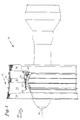
- Fig. 5 is a fragmentary, partially exploded perspective view of a fan vane employed in the engine of Fig. 1, illustrating the vibration damping shroud embodying the present invention.
- Fig. 6 is a fragmentary, exploded perspective view of the vibration damping shroud of Fig. 5.
- Fig. 7 is a plan view taken along section line 7-7 of Fig. 5.
- a gas turbine engine 10 includes a fan section 12 having a row of blades 14 which rotate about a central longitudinal axis 16 and a row of nonrotating stator vanes 18.
- the blades and vanes extend radially across an annular flow path 20 and the vanes are joined to both inner and outer cases 22 and 24.
- Nonrotating structural support struts 28 connect the inner and outer cases.
- each vane is securely joined to the outer case in a conventional manner that resists displacement of the vane relative to the case in all directions--longitudinally, circumferentially and radially.
- the end of the vane so secured is referred to generally as the fixed end.
- the fixed end of each vane fits into an aperture 40 (Fig. 3) formed in outer shroud segment 42.
- a sidewall 44 Fig. 2 extends radially outwardly from the aperture to define an open ended compartment 46 for receiving the outer end of the vane 18.
- a vibration damping material 48 also known as a potting material, is disposed in the compartment to bond the shroud to the vane and, when the vanes are assembled in an engine, to damp vane vibrations and resist displacement of the vane.
- the shroud segment 42 includes a pair of threaded studs 50 which are secured within and protruded radially outward from socket 32 immediately adjacent the compartment 46.
- the studs project through the outer case 24 (shown slightly exploded in Fig. 2 for clarity) where nuts 56 are threaded onto the studs to connect the vane to the outer case.
- each shroud cooperates with the circumferentially adjacent shrouds to define the outer flow path boundary.
- valve 30 (Fig. 1) may be provided to periodically bleed hot compressed air from an engine core compressor 32 and into an annular manifold 34, from where it is subsequently ducted overboard to preclude engine stall.
- the presence of hot air in the manifold expands the inner case in the radial direction since the case forms a portion of the manifold wall. Therefore, a pinned connection is used to anchor the vane inner end to the inner case in a manner that accommodates radial displacement between the vane and the case.
- the end of the vane secured in this fashion is generally referred to as the free end.
- a prior art pinned connection for anchoring each vane to the inner case is illustrated in Figs. 3 and 4.
- a longitudinally and circumferentially extending nonmetallic shroud 60 is attached to the inner end of each vane.
- the shroud contains an aperture 62 (Fig. 2) in the general shape of the airfoil cross section of the vane.
- a sidewall 64 at the perimeter of the aperture defines a compartment 66 extending radially away from the fan flow path.
- the vane 18 fits into the compartment, where a vibration damping material 68 fills the void between the sidewall and the vane, thereby gripping the vane and securing the shroud thereto.
- a metallic base plate 70 is bonded to the shroud by an adhesive, (not shown).
- One or more metallic support pins 72 extending radially outwardly from the inner case 22 pass through holes 73 in the base plate and penetrate into the vibration damping material to complete the connection between the vane and the case.
- the support pin diameter is smaller than the hole diameter so that the low amplitude vane vibrations that occur during normal operation do not cause the perimeter of the hole to contact the pin.
- the hole diameter is small enough that if the secondary material is lost, for example by melting, the perimeter of the base plate hole is urged against the pin by the aerodynamic forces on the vane, limiting further displacement of the vane and preventing potentially damaging contact between the pin and the sidewall 64.
- each shroud abuts the circumferentially adjacent shrouds to form an inner flow path boundary.
- the damping material joins each vane to its shroud, resists relative displacement therebetween and damps vibrations that occur during engine operation.
- the conventional pinned connection may be inadequate.
- the pins conduct heat into the damping material. If the temperature of the damping material is elevated beyond its transition temperature, the material in the vicinity of the pins becomes too soft to resist longitudinal and circumferential displacement of the vane. Although a material having a higher transition temperature can be substituted, such materials tend to be more resilient than those with lower transition temperatures. If such a resilient material is distributed throughout the compartment, the vane's natural vibratory frequency can be depressed so that it coincides with one of the excitory frequencies that normally occurs during engine operation. For example, aerodynamic wakes emanating from the rotating blades 14 (Fig. 1) strike each vane at a frequency determined by the blade rotational speed.
- a nonmetallic shroud 78 which extends longitudinally and circumferentially to form a portion of the inner flow path boundary has an aperture 80.
- a sidewall 82 extends radially from the aperture to define a chamber 84 for receiving the inner end of each vane 18.
- a primary damping material 86 fills the void between the chamber sidewall and the vane to secure the shroud to the vane, resist displacement of the vane arising from aerodynamic loads thereon, and damp vane vibrations that occur during engine operation.
- the shroud also has at least one radially extending cavity 88 defined by a cavity wall 90.
- Each cavity is independent of the chamber and contains a secondary vibration damping material which, in the preferred embodiment, is in the form of a sleeve 92.
- the secondary material slidably engages the corresponding support pin 72 which extends from the inner case 22 to anchor the vane to the case in a manner that is longitudinally and circumferentially secure but radially unrestrained.
- the primary and secondary vibration damping materials are chosen for their ability to satisfy the aforementioned conflicting requirements. Owing to the segregation of the chamber and the cavities, heat from the support pins is not readily transferred into the primary material, and the primary material is thus selected largely for its ability to adequately damp vane vibrations while maintaining the vane natural frequency higher than the excitory frequencies to which the vane is exposed during engine operation. It is unnecessary to compromise this ability by selecting a material of high transition temperature.
- the secondary material is chosen largely for its ability to tolerate elevated temperatures without becoming so soft that it is incapable of resisting relative displacement between the shroud and the pins. Accordingly, the secondary material has a higher transition temperature than the primary material.
- the applicability of the shroud can also be extended to environments that do not demand materials with different transition temperatures. In these circumstances, materials of equal transition temperature, or even the same material, are used in the cavities as well as the chamber.
- the relative proportions of the primary and secondary materials, and therefore the volumes of the chamber and the cavities, are selected so that the primary material has a greater influence than the secondary material on the dynamic behavior of the vane. If the quantity of primary material significantly exceeds that of the secondary material, the vibrational damping characteristics and natural frequency of the vane will be similar to that associated with the primary material alone. Therefore, the chamber volume is larger than the combined volume of the cavities so that the natural frequency of vane vibration is not depressed into the range of the excitory vibratory frequencies encountered during engine operation.
- the primary material is polyurethane and the secondary material is silicone rubber in the form of a sleeve secured to the inner surface of its cavity.
- the shroud of the present invention is entirely compatible with a damage limiting base plate like that of the prior art. Therefore, the invention may also be used with a base plate 96 made of a metal or other material dissimilar to the shroud material and secured thereto.
- the base plate has a hole 98 associated with each pin receiving cavity 88 and corresponding pin 72, with the hole diameter smaller than that of the cavity.
- Each support pin extends through the associated base plate hole to reach into the corresponding receiving cavity.
- the primary damping material absorbs the vibratory energy of the vane thereby damping the vibrations, secures the vane to the shroud, and transmits the aerodynamic forces acting on the vane into the shroud.
- the secondary material transmits those forces from the shroud to the support pins so that circumferential and longitudinal displacement of the vane is resisted. Thermally induced growth or contraction of the case relative to the vanes causes each support pin to slide radially along the surrounding sleeve of secondary material.
- the secondary material being limited in quantity relative to the primary material, plays an inappreciable role in damping vane vibrations.
- the vane vibrations are substantially confined to a plane perpendicular to the longitudinal central axis. Therefore, the width of the base plate hole, that is its dimension parallel to the plane of vibration, is smaller than the corresponding width of the cavity. If this were not so, or if the base plate were absent, displacement of the free end following loss of the secondary material would not be limited, and could bring the pin into contact with the cavity wall. Since the metallic pin had been heated to a high temperature due to frictional resistance of the secondary material, such contact can melt the nonmetallic cavity wall resulting in a complete loss of support at the inner end of the vane.
- the shroud, vane, secondary material sleeve and base plate are manufactured separately and assembled prior to being installed in an engine.
- a sleeve of the secondary material is placed in each cavity along with a suitable adhesive, such as an epoxy paste, for bonding the sleeve to the cavity wall.
- the base plate is positioned against the sidewall with a suitable adhesive therebetween, for example the same polyurethane that is used as the first vibration damping material.
- a first assembly fixture (not shown) positions the vane in the chamber so that the vane surface is spaced apart from the chamber sidewall. The fixture also seats against the radially inward extremity of the sidewalls to hold the base plate in place and to seal off the inner end of the chamber.
- a second fixture (not shown) seats against the radially outer or flow path side of the shroud to complete the sealing off of the vane receiving chamber.
- a quantity of the primary material is injected into the chamber through injection ports in the first fixture.
- the assembly is then heated to cure the adhesives and damping materials, after which the fixtures are removed and the vane is installed in an engine.
- the shroud has also been illustrated as having a single chamber for receiving a single vane and a pair of cavities for receiving corresponding support pins.
- any suitable number of support pins and cavities can be used, and multiple chambers for receiving multiple vanes can be provided without departing from the invention as claimed.
Landscapes
- Engineering & Computer Science (AREA)
- Mechanical Engineering (AREA)
- General Engineering & Computer Science (AREA)
- Structures Of Non-Positive Displacement Pumps (AREA)
Description
Claims (6)
- A vibration damping shroud (78) for a turbomachine (10), the turbomachine having a row of stator vanes (18) extending radially across an annular flow path (20) formed between an inner case (22) and an outer case (24), each vane having a fixed end securely joined to one of said inner and outer cases, each vane also having a free end capable of relative radial displacement with respect to the other of said inner and outer cases and anchored thereto by said vibration damping shroud (78), said shroud having a chamber (84) for receiving said free end and also having a primary vibration damping material (86) disposed in said chamber for securing said free end to said shroud and for damping vibrations of said vane, said other case also having at least one radially extending support pin (72) corresponding to each of said vanes, said shroud characterized by:a support pin cavity (88) independent of said chamber and located in said shroud (78) for receiving each corresponding support pin; anda secondary vibration damping material (92) disposed in said cavity (88) and slidably engaging said pin (72) for anchoring said shroud to said other case while accommodating relative radial displacement therebetween.
- The vibration damping shroud (78) of claim 1 characterized by the resilience of said primary vibration damping material (86) being such that the natural vibrational frequency of said vane (18) is higher than the excitory vibrational frequencies to which said vane is exposed during engine operation, and the transition temperature of said secondary vibration damping material (92) being at least as high as that of said primary material (86).
- The vibration damping shroud (78) of claim 2 characterized by the volume of said chamber (84) being greater than the combined volume of said cavities (88) so that the natural frequency of vane vibration is higher than the excitory vibratory frequencies encountered during normal engine operation.
- The vibration damping shroud (78) of any preceding claim characterized by a base plate (96) of material having a higher melting temperature than that of said shroud and secured to said shroud, said base plate having a hole (98) associated with each of said cavities (88) and corresponding support pins (72) for enabling said pins to extend through said base plate and into said cavity, each hole being dimensioned to preclude contact between said pin and said cavity wall in the event of the loss of the secondary vibration damping material (92).
- The vibration damping shroud (78) of any preceding claim characterized by said primary vibration damping material (86) comprising polyurethane and said secondary vibration damping material (92) comprising silicon rubber.
- The vibration damping shroud (78) of any preceding claim characterized by said cavity (88) being defined by a cavity wall (90) and said secondary material comprising a sleeve (92) secured to the inner surface of said cavity wall.
Applications Claiming Priority (3)
| Application Number | Priority Date | Filing Date | Title |
|---|---|---|---|
| US08/283,883 US5411370A (en) | 1994-08-01 | 1994-08-01 | Vibration damping shroud for a turbomachine vane |
| PCT/US1995/009277 WO1996004468A1 (en) | 1994-08-01 | 1995-07-20 | Vibration damping shroud for a turbomachine vane |
| US283883 | 2005-11-22 |
Publications (2)
| Publication Number | Publication Date |
|---|---|
| EP0839260A1 EP0839260A1 (en) | 1998-05-06 |
| EP0839260B1 true EP0839260B1 (en) | 1999-04-14 |
Family
ID=23087983
Family Applications (1)
| Application Number | Title | Priority Date | Filing Date |
|---|---|---|---|
| EP95928110A Expired - Lifetime EP0839260B1 (en) | 1994-08-01 | 1995-07-20 | Vibration damping shroud for a turbomachine vane |
Country Status (5)
| Country | Link |
|---|---|
| US (1) | US5411370A (en) |
| EP (1) | EP0839260B1 (en) |
| JP (1) | JP3701680B2 (en) |
| DE (1) | DE69509137T2 (en) |
| WO (1) | WO1996004468A1 (en) |
Families Citing this family (43)
| Publication number | Priority date | Publication date | Assignee | Title |
|---|---|---|---|---|
| US5630700A (en) * | 1996-04-26 | 1997-05-20 | General Electric Company | Floating vane turbine nozzle |
| US5690469A (en) * | 1996-06-06 | 1997-11-25 | United Technologies Corporation | Method and apparatus for replacing a vane assembly in a turbine engine |
| US5820348A (en) | 1996-09-17 | 1998-10-13 | Fricke; J. Robert | Damping system for vibrating members |
| US5765993A (en) * | 1996-09-27 | 1998-06-16 | Chromalloy Gas Turbine Corporation | Replacement vane assembly for fan exit guide |
| JPH11247605A (en) | 1997-12-26 | 1999-09-14 | United Technol Corp <Utc> | Vibration-damping method and apparatus of turbo machine component |
| US6206155B1 (en) | 1998-09-22 | 2001-03-27 | The Unites States Of America As Represented By The Administrator Of The National Aeronautics And Space Administration | Energy absorbing protective shroud |
| US6343912B1 (en) * | 1999-12-07 | 2002-02-05 | General Electric Company | Gas turbine or jet engine stator vane frame |
| US6371725B1 (en) * | 2000-06-30 | 2002-04-16 | General Electric Company | Conforming platform guide vane |
| US6464456B2 (en) * | 2001-03-07 | 2002-10-15 | General Electric Company | Turbine vane assembly including a low ductility vane |
| US7651319B2 (en) * | 2002-02-22 | 2010-01-26 | Drs Power Technology Inc. | Compressor stator vane |
| US6984108B2 (en) * | 2002-02-22 | 2006-01-10 | Drs Power Technology Inc. | Compressor stator vane |
| US6814541B2 (en) | 2002-10-07 | 2004-11-09 | General Electric Company | Jet aircraft fan case containment design |
| GB2400415B (en) * | 2003-04-11 | 2006-03-08 | Rolls Royce Plc | Vane mounting |
| GB2427900B (en) * | 2005-07-02 | 2007-10-10 | Rolls Royce Plc | Vane support in a gas turbine engine |
| FR2913048B1 (en) * | 2007-02-28 | 2009-04-10 | Snecma Sa | TURBOMACHINE BLOWER |
| US20090022579A1 (en) * | 2007-07-17 | 2009-01-22 | Schlichting Kevin W | Burn resistant organic matrix composite material |
| US20090110552A1 (en) * | 2007-10-31 | 2009-04-30 | Anderson Rodger O | Compressor stator vane repair with pin |
| US8511983B2 (en) | 2008-02-19 | 2013-08-20 | United Technologies Corporation | LPC exit guide vane and assembly |
| US8043044B2 (en) * | 2008-09-11 | 2011-10-25 | General Electric Company | Load pin for compressor square base stator and method of use |
| ES2370307B1 (en) * | 2008-11-04 | 2012-11-27 | Industria De Turbo Propulsores, S.A. | BEARING SUPPORT STRUCTURE FOR TURBINE. |
| WO2011050229A2 (en) | 2009-10-23 | 2011-04-28 | Dresser-Rand Company | Energy conversion system with duplex radial flow turbine |
| US9650897B2 (en) * | 2010-02-26 | 2017-05-16 | United Technologies Corporation | Hybrid metal fan blade |
| US20110211965A1 (en) * | 2010-02-26 | 2011-09-01 | United Technologies Corporation | Hollow fan blade |
| US8544173B2 (en) * | 2010-08-30 | 2013-10-01 | General Electric Company | Turbine nozzle biform repair |
| EP2615246A1 (en) * | 2012-01-16 | 2013-07-17 | MTU Aero Engines GmbH | Stator blade ring, stator blade segment, method for producing a stator blade segment and a flow engine |
| US8438832B1 (en) | 2012-01-31 | 2013-05-14 | United Technologies Corporation | High turning fan exit stator |
| US9109448B2 (en) | 2012-03-23 | 2015-08-18 | Pratt & Whitney Canada Corp. | Grommet for gas turbine vane |
| US9334751B2 (en) | 2012-04-03 | 2016-05-10 | United Technologies Corporation | Variable vane inner platform damping |
| US20130333350A1 (en) | 2012-06-19 | 2013-12-19 | Nicholas D. Stilin | Airfoil including adhesively bonded shroud |
| US11035238B2 (en) | 2012-06-19 | 2021-06-15 | Raytheon Technologies Corporation | Airfoil including adhesively bonded shroud |
| US9228438B2 (en) | 2012-12-18 | 2016-01-05 | United Technologies Corporation | Variable vane having body formed of first material and trunnion formed of second material |
| EP2971575B1 (en) * | 2013-03-13 | 2017-12-27 | United Technologies Corporation | Structural guide vane outer diameter k gussets |
| EP3011141B1 (en) * | 2013-06-17 | 2020-02-26 | United Technologies Corporation | Turbine vane with platform pad |
| US20160177732A1 (en) * | 2014-07-22 | 2016-06-23 | United Technologies Corporation | Hollow fan blade for a gas turbine engine |
| JP6503698B2 (en) * | 2014-11-17 | 2019-04-24 | 株式会社Ihi | Axial machine wing |
| US10309240B2 (en) | 2015-07-24 | 2019-06-04 | General Electric Company | Method and system for interfacing a ceramic matrix composite component to a metallic component |
| US10450897B2 (en) * | 2016-07-18 | 2019-10-22 | General Electric Company | Shroud for a gas turbine engine |
| FR3059706B1 (en) * | 2016-12-02 | 2020-10-23 | Safran Aircraft Engines | FLOW RECTIFIER FOR TURBOMACHINE WITH REMOVABLE FIXING |
| DE102018132892A1 (en) * | 2018-12-19 | 2020-06-25 | Rolls-Royce Deutschland Ltd & Co Kg | Intermediate housing structure for a compressor device of a gas turbine engine and a gas turbine engine |
| US11286798B2 (en) * | 2019-08-20 | 2022-03-29 | Rolls-Royce Corporation | Airfoil assembly with ceramic matrix composite parts and load-transfer features |
| DE102020215576A1 (en) * | 2020-12-09 | 2022-06-09 | Rolls-Royce Deutschland Ltd & Co Kg | Flow director and a gas turbine engine |
| US11428160B2 (en) | 2020-12-31 | 2022-08-30 | General Electric Company | Gas turbine engine with interdigitated turbine and gear assembly |
| EP4697570A1 (en) * | 2024-08-14 | 2026-02-18 | ALSTOM Holdings | Cooling device for a vehicle electric traction motor, related motorization assembly and vehicle, and related manufacturing method |
Family Cites Families (12)
| Publication number | Priority date | Publication date | Assignee | Title |
|---|---|---|---|---|
| BE570533A (en) * | 1957-08-22 | |||
| US3778184A (en) * | 1972-06-22 | 1973-12-11 | United Aircraft Corp | Vane damping |
| US3932056A (en) * | 1973-09-27 | 1976-01-13 | Barry Wright Corporation | Vane damping |
| GB2043798B (en) * | 1979-03-14 | 1983-01-12 | Rolls Royce | Gas turbine stator vane assembly |
| GB2115883B (en) * | 1982-02-26 | 1986-04-30 | Gen Electric | Turbomachine airfoil mounting assembly |
| US4655682A (en) * | 1985-09-30 | 1987-04-07 | United Technologies Corporation | Compressor stator assembly having a composite inner diameter shroud |
| FR2600379B1 (en) * | 1986-06-18 | 1988-09-02 | Snecma | MULTIFLUX TURBOJET BLOWER RECTIFIER |
| FR2606071B1 (en) * | 1986-10-29 | 1990-11-30 | Snecma | STATOR STAGE AND TURBOMACHINE COMPRESSOR COMPRISING THE SAME |
| FR2610673B1 (en) * | 1987-02-05 | 1991-03-15 | Snecma | MULTIFLUX TURBOREACTOR WITH EXTERNAL CROWN OF FREQUENCY BLOWER RECTIFIER ON THE CRANKCASE |
| US5074752A (en) * | 1990-08-06 | 1991-12-24 | General Electric Company | Gas turbine outlet guide vane mounting assembly |
| FR2685033B1 (en) * | 1991-12-11 | 1994-02-11 | Snecma | STATOR DIRECTING THE AIR INLET INSIDE A TURBOMACHINE AND METHOD FOR MOUNTING A VANE OF THIS STATOR. |
| US5346362A (en) * | 1993-04-26 | 1994-09-13 | United Technologies Corporation | Mechanical damper |
-
1994
- 1994-08-01 US US08/283,883 patent/US5411370A/en not_active Expired - Lifetime
-
1995
- 1995-07-20 JP JP50657696A patent/JP3701680B2/en not_active Expired - Fee Related
- 1995-07-20 EP EP95928110A patent/EP0839260B1/en not_active Expired - Lifetime
- 1995-07-20 WO PCT/US1995/009277 patent/WO1996004468A1/en not_active Ceased
- 1995-07-20 DE DE69509137T patent/DE69509137T2/en not_active Expired - Lifetime
Also Published As
| Publication number | Publication date |
|---|---|
| WO1996004468A1 (en) | 1996-02-15 |
| DE69509137T2 (en) | 1999-11-18 |
| US5411370A (en) | 1995-05-02 |
| JPH10503819A (en) | 1998-04-07 |
| EP0839260A1 (en) | 1998-05-06 |
| DE69509137D1 (en) | 1999-05-20 |
| JP3701680B2 (en) | 2005-10-05 |
Similar Documents
| Publication | Publication Date | Title |
|---|---|---|
| US5411370A (en) | Vibration damping shroud for a turbomachine vane | |
| JP4017216B2 (en) | Turbine blade damper and seal | |
| EP1529926B1 (en) | Spring and damper system for turbine shrouds | |
| US7238002B2 (en) | Damper seal system and method | |
| US7520718B2 (en) | Seal and locking plate for turbine rotor assembly between turbine blade and turbine vane | |
| JP5887130B2 (en) | Structurally low ductility turbine shroud device | |
| US6969239B2 (en) | Apparatus and method for damping vibrations between a compressor stator vane and a casing of a gas turbine engine | |
| KR100405881B1 (en) | Shroud for rotor assembly, shroud for gas turbine rotor assembly and suspension apparatus | |
| EP1219785B1 (en) | Gas turbine engine vane installation | |
| CN105134304B (en) | Angular sector of the downstream guide vanes for a turbine engine compressor, turbine engine downstream guide vanes and turbine engine including such a sector | |
| EP1240411B1 (en) | Split ring for tip clearance control | |
| CN102213108A (en) | Composite turbine bucket assembly | |
| US20170298748A1 (en) | Gas turbine engine with compliant layer for turbine vane assemblies | |
| EP1079075A2 (en) | Stator assembly for a rotary machine and clip member for a stator assembly | |
| JPH1037701A (en) | Blade for turbomachine thermally loaded | |
| JP4125891B2 (en) | Gas turbine blade and gas turbine | |
| JPS5855360B2 (en) | Blade platform vibration damping device | |
| JP2011157968A (en) | Mounting device for low-ductility turbine shroud | |
| US4378961A (en) | Case assembly for supporting stator vanes | |
| JPH0424527B2 (en) | ||
| JPS62111102A (en) | Method of assembling bucket aggregate with tangential insertion type dovetail section to turbo machine impeller | |
| CA2957229A1 (en) | Gas turbine engine with compliant layer for turbine shroud mounts | |
| US11286798B2 (en) | Airfoil assembly with ceramic matrix composite parts and load-transfer features | |
| US3451654A (en) | Blade vibration damping | |
| JPH0477121B2 (en) |
Legal Events
| Date | Code | Title | Description |
|---|---|---|---|
| PUAI | Public reference made under article 153(3) epc to a published international application that has entered the european phase |
Free format text: ORIGINAL CODE: 0009012 |
|
| 17P | Request for examination filed |
Effective date: 19970228 |
|
| AK | Designated contracting states |
Kind code of ref document: A1 Designated state(s): DE FR GB |
|
| GRAG | Despatch of communication of intention to grant |
Free format text: ORIGINAL CODE: EPIDOS AGRA |
|
| 17Q | First examination report despatched |
Effective date: 19980728 |
|
| GRAG | Despatch of communication of intention to grant |
Free format text: ORIGINAL CODE: EPIDOS AGRA |
|
| GRAH | Despatch of communication of intention to grant a patent |
Free format text: ORIGINAL CODE: EPIDOS IGRA |
|
| GRAH | Despatch of communication of intention to grant a patent |
Free format text: ORIGINAL CODE: EPIDOS IGRA |
|
| GRAA | (expected) grant |
Free format text: ORIGINAL CODE: 0009210 |
|
| AK | Designated contracting states |
Kind code of ref document: B1 Designated state(s): DE FR GB |
|
| ET | Fr: translation filed | ||
| REF | Corresponds to: |
Ref document number: 69509137 Country of ref document: DE Date of ref document: 19990520 |
|
| PLBE | No opposition filed within time limit |
Free format text: ORIGINAL CODE: 0009261 |
|
| STAA | Information on the status of an ep patent application or granted ep patent |
Free format text: STATUS: NO OPPOSITION FILED WITHIN TIME LIMIT |
|
| 26N | No opposition filed | ||
| REG | Reference to a national code |
Ref country code: GB Ref legal event code: IF02 |
|
| PGFP | Annual fee paid to national office [announced via postgrant information from national office to epo] |
Ref country code: FR Payment date: 20100805 Year of fee payment: 16 |
|
| REG | Reference to a national code |
Ref country code: FR Ref legal event code: ST Effective date: 20120330 |
|
| PG25 | Lapsed in a contracting state [announced via postgrant information from national office to epo] |
Ref country code: FR Free format text: LAPSE BECAUSE OF NON-PAYMENT OF DUE FEES Effective date: 20110801 |
|
| PGFP | Annual fee paid to national office [announced via postgrant information from national office to epo] |
Ref country code: DE Payment date: 20140716 Year of fee payment: 20 |
|
| PGFP | Annual fee paid to national office [announced via postgrant information from national office to epo] |
Ref country code: GB Payment date: 20140716 Year of fee payment: 20 |
|
| REG | Reference to a national code |
Ref country code: DE Ref legal event code: R071 Ref document number: 69509137 Country of ref document: DE |
|
| REG | Reference to a national code |
Ref country code: GB Ref legal event code: PE20 Expiry date: 20150719 |
|
| PG25 | Lapsed in a contracting state [announced via postgrant information from national office to epo] |
Ref country code: GB Free format text: LAPSE BECAUSE OF EXPIRATION OF PROTECTION Effective date: 20150719 |