EP0838836B1 - Thermoelectric cooling in gas-assisted focused ion beam (FIB) system - Google Patents
Thermoelectric cooling in gas-assisted focused ion beam (FIB) system Download PDFInfo
- Publication number
- EP0838836B1 EP0838836B1 EP97402304A EP97402304A EP0838836B1 EP 0838836 B1 EP0838836 B1 EP 0838836B1 EP 97402304 A EP97402304 A EP 97402304A EP 97402304 A EP97402304 A EP 97402304A EP 0838836 B1 EP0838836 B1 EP 0838836B1
- Authority
- EP
- European Patent Office
- Prior art keywords
- crucible
- temperature
- peltier element
- flow path
- powering
- Prior art date
- Legal status (The legal status is an assumption and is not a legal conclusion. Google has not performed a legal analysis and makes no representation as to the accuracy of the status listed.)
- Expired - Lifetime
Links
- 238000010884 ion-beam technique Methods 0.000 title claims description 6
- 238000001816 cooling Methods 0.000 title description 10
- 239000000126 substance Substances 0.000 claims description 33
- 238000010438 heat treatment Methods 0.000 claims description 19
- 238000004891 communication Methods 0.000 claims description 15
- 238000000034 method Methods 0.000 claims description 8
- 239000012080 ambient air Substances 0.000 claims description 4
- 238000012544 monitoring process Methods 0.000 claims description 4
- 239000007789 gas Substances 0.000 description 33
- 238000002347 injection Methods 0.000 description 19
- 239000007924 injection Substances 0.000 description 19
- 239000000463 material Substances 0.000 description 14
- 239000002390 adhesive tape Substances 0.000 description 6
- 238000012545 processing Methods 0.000 description 6
- 150000001875 compounds Chemical class 0.000 description 5
- 125000006850 spacer group Chemical group 0.000 description 5
- 238000010586 diagram Methods 0.000 description 4
- 239000000523 sample Substances 0.000 description 4
- 229910001220 stainless steel Inorganic materials 0.000 description 4
- 239000010935 stainless steel Substances 0.000 description 4
- 150000002500 ions Chemical class 0.000 description 3
- 239000002245 particle Substances 0.000 description 3
- 238000012360 testing method Methods 0.000 description 3
- 238000012546 transfer Methods 0.000 description 3
- 239000004809 Teflon Substances 0.000 description 2
- 229920006362 Teflon® Polymers 0.000 description 2
- 230000005494 condensation Effects 0.000 description 2
- 238000009833 condensation Methods 0.000 description 2
- 239000004020 conductor Substances 0.000 description 2
- 238000005516 engineering process Methods 0.000 description 2
- 238000003384 imaging method Methods 0.000 description 2
- 238000009413 insulation Methods 0.000 description 2
- 238000005259 measurement Methods 0.000 description 2
- 238000003801 milling Methods 0.000 description 2
- 230000004044 response Effects 0.000 description 2
- 238000007664 blowing Methods 0.000 description 1
- 238000004140 cleaning Methods 0.000 description 1
- 238000010276 construction Methods 0.000 description 1
- 230000008021 deposition Effects 0.000 description 1
- 238000013461 design Methods 0.000 description 1
- 230000008030 elimination Effects 0.000 description 1
- 238000003379 elimination reaction Methods 0.000 description 1
- 239000007788 liquid Substances 0.000 description 1
- 238000012986 modification Methods 0.000 description 1
- 230000004048 modification Effects 0.000 description 1
- 230000003287 optical effect Effects 0.000 description 1
- 238000005086 pumping Methods 0.000 description 1
- 239000007787 solid Substances 0.000 description 1
- 239000007921 spray Substances 0.000 description 1
- 230000000087 stabilizing effect Effects 0.000 description 1
- 238000011144 upstream manufacturing Methods 0.000 description 1
- 239000013598 vector Substances 0.000 description 1
- 239000002699 waste material Substances 0.000 description 1
Images


Classifications
-
- C—CHEMISTRY; METALLURGY
- C23—COATING METALLIC MATERIAL; COATING MATERIAL WITH METALLIC MATERIAL; CHEMICAL SURFACE TREATMENT; DIFFUSION TREATMENT OF METALLIC MATERIAL; COATING BY VACUUM EVAPORATION, BY SPUTTERING, BY ION IMPLANTATION OR BY CHEMICAL VAPOUR DEPOSITION, IN GENERAL; INHIBITING CORROSION OF METALLIC MATERIAL OR INCRUSTATION IN GENERAL
- C23C—COATING METALLIC MATERIAL; COATING MATERIAL WITH METALLIC MATERIAL; SURFACE TREATMENT OF METALLIC MATERIAL BY DIFFUSION INTO THE SURFACE, BY CHEMICAL CONVERSION OR SUBSTITUTION; COATING BY VACUUM EVAPORATION, BY SPUTTERING, BY ION IMPLANTATION OR BY CHEMICAL VAPOUR DEPOSITION, IN GENERAL
- C23C16/00—Chemical coating by decomposition of gaseous compounds, without leaving reaction products of surface material in the coating, i.e. chemical vapour deposition [CVD] processes
- C23C16/44—Chemical coating by decomposition of gaseous compounds, without leaving reaction products of surface material in the coating, i.e. chemical vapour deposition [CVD] processes characterised by the method of coating
- C23C16/455—Chemical coating by decomposition of gaseous compounds, without leaving reaction products of surface material in the coating, i.e. chemical vapour deposition [CVD] processes characterised by the method of coating characterised by the method used for introducing gases into reaction chamber or for modifying gas flows in reaction chamber
- C23C16/45502—Flow conditions in reaction chamber
- C23C16/4551—Jet streams
-
- C—CHEMISTRY; METALLURGY
- C23—COATING METALLIC MATERIAL; COATING MATERIAL WITH METALLIC MATERIAL; CHEMICAL SURFACE TREATMENT; DIFFUSION TREATMENT OF METALLIC MATERIAL; COATING BY VACUUM EVAPORATION, BY SPUTTERING, BY ION IMPLANTATION OR BY CHEMICAL VAPOUR DEPOSITION, IN GENERAL; INHIBITING CORROSION OF METALLIC MATERIAL OR INCRUSTATION IN GENERAL
- C23C—COATING METALLIC MATERIAL; COATING MATERIAL WITH METALLIC MATERIAL; SURFACE TREATMENT OF METALLIC MATERIAL BY DIFFUSION INTO THE SURFACE, BY CHEMICAL CONVERSION OR SUBSTITUTION; COATING BY VACUUM EVAPORATION, BY SPUTTERING, BY ION IMPLANTATION OR BY CHEMICAL VAPOUR DEPOSITION, IN GENERAL
- C23C14/00—Coating by vacuum evaporation, by sputtering or by ion implantation of the coating forming material
- C23C14/22—Coating by vacuum evaporation, by sputtering or by ion implantation of the coating forming material characterised by the process of coating
- C23C14/221—Ion beam deposition
-
- F—MECHANICAL ENGINEERING; LIGHTING; HEATING; WEAPONS; BLASTING
- F25—REFRIGERATION OR COOLING; COMBINED HEATING AND REFRIGERATION SYSTEMS; HEAT PUMP SYSTEMS; MANUFACTURE OR STORAGE OF ICE; LIQUEFACTION SOLIDIFICATION OF GASES
- F25B—REFRIGERATION MACHINES, PLANTS OR SYSTEMS; COMBINED HEATING AND REFRIGERATION SYSTEMS; HEAT PUMP SYSTEMS
- F25B21/00—Machines, plants or systems, using electric or magnetic effects
- F25B21/02—Machines, plants or systems, using electric or magnetic effects using Peltier effect; using Nernst-Ettinghausen effect
- F25B21/04—Machines, plants or systems, using electric or magnetic effects using Peltier effect; using Nernst-Ettinghausen effect reversible
-
- H—ELECTRICITY
- H01—ELECTRIC ELEMENTS
- H01J—ELECTRIC DISCHARGE TUBES OR DISCHARGE LAMPS
- H01J37/00—Discharge tubes with provision for introducing objects or material to be exposed to the discharge, e.g. for the purpose of examination or processing thereof
- H01J37/30—Electron-beam or ion-beam tubes for localised treatment of objects
- H01J37/305—Electron-beam or ion-beam tubes for localised treatment of objects for casting, melting, evaporating, or etching
- H01J37/3053—Electron-beam or ion-beam tubes for localised treatment of objects for casting, melting, evaporating, or etching for evaporating or etching
- H01J37/3056—Electron-beam or ion-beam tubes for localised treatment of objects for casting, melting, evaporating, or etching for evaporating or etching for microworking, e. g. etching of gratings or trimming of electrical components
-
- H—ELECTRICITY
- H01—ELECTRIC ELEMENTS
- H01J—ELECTRIC DISCHARGE TUBES OR DISCHARGE LAMPS
- H01J2237/00—Discharge tubes exposing object to beam, e.g. for analysis treatment, etching, imaging
- H01J2237/006—Details of gas supplies, e.g. in an ion source, to a beam line, to a specimen or to a workpiece
-
- H—ELECTRICITY
- H01—ELECTRIC ELEMENTS
- H01J—ELECTRIC DISCHARGE TUBES OR DISCHARGE LAMPS
- H01J2237/00—Discharge tubes exposing object to beam, e.g. for analysis treatment, etching, imaging
- H01J2237/30—Electron or ion beam tubes for processing objects
- H01J2237/317—Processing objects on a microscale
- H01J2237/3174—Etching microareas
- H01J2237/31742—Etching microareas for repairing masks
- H01J2237/31744—Etching microareas for repairing masks introducing gas in vicinity of workpiece
Definitions
- the present invention relates to methods and apparatus for conducting focused-ion-beam (FIB) operations on integrated circuits.
- FIB focused-ion-beam
- a FIB is used to mill away material to expose a conductor and/or to cut a conductor, while introducing a gas or gases to selectively enhance the milling rate of the material to be removed. See, for example, pending U.S. patent application 08/268,790, filed June 30, 1994 of Talbot et al . (US-A-5 616 921).
- a FIB can also be used to selectively deposit conductive and insulative material by introducing a suitable gas or gases near the working region of the FIB. See, for example, U.S. Patent No. 5,104,684 to Tao et al . and pending U.S.
- FIG. 1 shows a schematic diagram of a typical prior-art system 110 for conducting such operations.
- System 110 has three main functional elements: a FIB probe 112, a circuit exerciser 114, and a data processing system 116 which includes a display terminal 118.
- An IC 126 is placed in a vacuum chamber 128 of FIB probe 112.
- Circuit exerciser 114 may be a conventional IC tester which can repeatedly apply a pattern of test vectors to IC 126 over a bus in response to commands received from data processing system 116 over bus 110.
- the FIB can be aimed at a desired location on the IC in response to commands supplied from data processing system 116 over bus 122.
- a charged particle detector within FIB probe 112 supplies measurements of the energy of secondary charged particles to data processing system 116 over bus 122.
- Data processing system 116 may be commanded by an operator to specify the test signal pattern used and the timing of measurements relative to the test signal pattern.
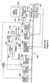
- FIG. 2 shows a more detailed schematic diagram of such a FIB system 200.
- a vacuum chamber 202 evacuated by pumps 204 encloses a FIB column 206, a specimen stage 208. for holding a specimen 210 such as an IC device to be repaired, a detector 212, and a gas injector 214.
- Column 206 includes an ion source 216, and ion-optical elements 218 for controlling alignment and deflection of an ion beam 220.
- Detector 212 may comprise a scintillator 222 and a photo-multiplier tube 224 for detecting secondary electrons 226 emitted when ion beam 220 impinges on specimen 210.
- the system includes a workstation 230 having a processor unit (CPU) 234, a monitor 236 and input/output (I/O) devices 238 such as a keyboard and/or mouse.
- Workstation 230 is linked by a bus 240 to a system control unit 242 comprising a control CPU, an image processor and image memory.
- System control unit 242 communicates via a bus 244 with a vacuum-pumps control 246 for controlling vacuum pumps 204, with gas injector control 248 for controlling gas injector 214, with FIB high-voltage control 250 for controlling ion source 216, with FIB alignment & deflection control 252 for controlling ion optical elements 218, with imaging electronics 254 which receive a detector signal from detector 212, and with specimen-stage control 256 for controlling specimen stage 208 to position specimen 210.
- System control unit 242 preferably receives image information from imaging electronics 254 and supplies beam control information to FIB alignment and deflection control 252.
- a specimen 210 is placed in vacuum chamber 202. Chamber 202 is evacuated. Under control of system control unit 242, FIB 220 is scanned over a selected region of the specimen to mill away material from the surface of specimen 210 and/or to deposit material on the surface of specimen 210. During milling and deposition, a suitable gas is injected at the surface of specimen 210 from gas injector 214.
- gas injector 214 In the Schlumberger IDS P2X FIBstation, for example, separate crucibles are provided for storage of multiple gas-producing compounds. The crucibles supply gas to an injector needle via a controllable manifold (not illustrated) so that rapid switch-over from one gas to another is possible upon command from the system control unit.
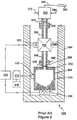
- FIG 3 schematically illustrates a portion 300 of prior-art gas injector 214 in partial cross-sectional view.
- a stainless-steel crucible 305 contains a solid or liquid chemical 310 to be used as a source for injection gas.
- a temperature controller 315 regulates temperature of crucible 305 by monitoring the output of a temperature sensor 320 and controlling a power supply 325 which powers a resistive heater 330. Temperature controller 315 is set by command from system control unit 242 so that a constant temperature suitable for the injection chemical is maintained in the crucible.
- Injection-chemical vapor passes from the crucible to a manifold 335 via first and second tube portions 340 and 345 joined at a connection 350, through a valve 355 which is controlled by gas injector control 248, and through third and fourth tube portions 360 and 365 joined at a connection 370.
- An O-ring seal 372 between crucible 305 and a flange 374 of tube portion 340 prevents unwanted release of vapor.
- Manifold 335 has additional input lines such as lines 375 and 380 for receiving vapors from other crucibles, and an output line 385 for supplying vapors to an injector needle 390.
- a resistive heater 392 powered by power supply 325 under control of temperature controller 315 maintains the temperature of vapor as it passes from crucible 305 to manifold 335. Insulation 394 is provided to help maintain an even temperature. The temperature of the chemical is thus maintained by a simple closed-loop control system in a range of about 10° - 60° Celcius.
- a restrictive aperture 396 is optionally provided in tube portion 340 to reduce the gas flow rate and allow the crucible temperature to be raised into the achievable range.
- Aperture 396 is typically mounted immediately above crucible 305, upstream of valve 355, in order to limit the volume of vapor contained behind the aperture and thus reduce the crucible pump-down time.
- a flow-restriction aperture with such chemicals has a number of disadvantages.
- Document EP-A-221 184 also discloses a compound vapour spray nozzle for a mask repairing apparatus having a crucible heated by a resistive heater.
- the present invention relates to an apparatus as claimed in claim 1 and to a method as claimed in claim 9.
- Preferred embodiments of the invention provide for thermoelectric cooling or heating of the crucible with a Peltier element. This can eliminate for some injection chemicals the need for a flow-restriction aperture. For other injection chemicals it can avoid some of the disadvantages otherwise encountered with the use of a flow-restriction aperture. Thermoelectric cooling can overcome difficulties associated with an aperture and can make possible the vapor-injection of chemicals which are otherwise impractical for use in FIB operations.
- the invention provides apparatus for supplying a jet of chemical vapor at a substantially constant rate, comprising a crucible for containing a quantity of chemical, a hollow needle, a flow path from the crucible to the hollow needle, a Peltier element in thermal communication with the crucible; and a temperature control circuit responsive to temperature in the crucible for powering the Peltier element so as to maintain temperature of the crucible substantially constant.
- the temperature control circuit powers the Peltier element so as to maintain temperature of the crucible below (or above) ambient temperature.
- the temperature control circuit may comprise a temperature sensor responsive to temperature in the crucible, a temperature controller responsive to the temperature sensor, and a power supply responsive to the temperature controller for powering the Peltier element.
- a heat sink in thermal communication with the Peltier element improves heat transfer.
- a fan for moving ambient air over the heat sink may also be used to enhance heat transfer.
- a controllable valve is provided in the flow path for starting and stopping flow of vapor to the hollow needle.
- a heating element may be provided in thermal communication with the flow path, along with a second temperature control circuit for powering the heating element so as to maintain temperature of the flow path substantially constant.
- the flow path preferably includes a thermally-insulative portion which provides a thermal break between the crucible and other portions of the flow path.
- the chemical-vapor supplying apparatus can be used as a subsystem of an apparatus for modifying an integrated circuit specimen which further comprises a vacuum chamber and an ion-optical column for directing a focused ion beam at an integrated circuit specimen within the vacuum chamber.
- Control of vapor pressure, and thus flow rate, offers improved control over FIB processing of integrated circuit specimens.
- Preferred methods in accordance with the invention comprise supplying a jet of chemical vapor at a substantially constant rate by storing a quantity of chemical in a crucible in thermal communication with a Peltier element, placing the crucible in communication with a hollow needle along a flow path from the crucible to the hollow needle, monitoring temperature in the crucible with a temperature sensor, and powering the Peltier element so as to maintain temperature of the crucible substantially constant.
- Ambient air may be passed over a heat sink in thermal communication with the Peltier element.
- the Peltier element is powered by supplying a current to the Peltier element so as to cool the crucible below ambient temperature or to warm the crucible above ambient temperature.
- FIG. 4 schematically illustrates a gas injector subsystem embodiment 400 in accordance with the invention in partial sectional view.
- a stainless-steel crucible 405 contains a chemical 410 to be used as a source for injection gas.
- a temperature controller 415 regulates temperature of crucible 405 by monitoring the output of a temperature sensor 420 and controlling a power supply 425 which powers a Peltier element (thermoelectric device) 430. Temperature controller is set by command from system control unit 248 so that a constant temperature suitable for the injection chemical is maintained in the crucible.
- Peltier element 430 is affixed to crucible 405 so as to provide a good heat conduction path between the two, such as with a strip 435 of double-sided thermally-conducting adhesive tape.
- a heat sink 440 is affixed to the opposite face of Peltier element 430 so as to provide a good heat-conduction path between the two, such as with a strip 445 of double-sided thermally-conducting adhesive tape. It is important to have thermally-conducting interfaces so as to avoid compromising efficiency of the system.
- a fan 450 which may also be powered by power supply 425 under control of temperature controller 415, is optionally provided to improve convective heat transfer between heat sink 440 and the atmosphere.
- Peltier element 430 can be a thermoelectric cooling element part number CP-1.0-127-06L, available from Melcor, Trenton, NJ, which can pump a maximum of 25 watts running at up to 15 volts and 3 amps.
- a convenient heat sink 440 for this application is the type intended for cooling of 80486 or Pentium microprocessor chips. These often are provided with double-sided, thermally-conducting adhesive tape which allows easy and efficient mounting to Peltier element 430. The same kind of adhesive tape can also be used to mate Peltier element 430 to the bottom of crucible 405 making assembly easy.
- Heat sink 440 can be an Aavid Engineering model 3302 heat sink. Alternatively, a heat sink and fan combination can be used, such as Sanyo Denki Co. part number 109P4405H8026. Double-sided thermally-conducting adhesive tape is available from Aavid Engineering under part number D037302385B.
- Temperature controller 415 can be an Auto-Tune PID (proportional, integral, derivative) controller part number CN-76000, available from Omega Engineering, Stamford, CT.
- the temperature controller reads the temperature from sensor 420 mounted on crucible 405 and outputs a signal voltage which controls a constant-current power supply capable of providing, for example, up to 1 amp at 5 volts DC. With the arrangement described, temperatures down to zero degrees Celcius are readily achieved with a small fan blowing on the heat sink in a room-temperature ambient environment. The parameters given can be altered when used with different models and makes of thermoelectric element 430.
- Peltier element 430 can also be used for heating crucible 405 by reversing the flow of current through the Peltier element.
- the arrangement described has been tested and found to easily lower the crucible temperature to as low as zero degrees Celcius or to raise the crucible temperature to the maximum desirable operating level of 60° Celcius.
- the operating temperature range can be extended by substituting a stacking of multiple Peltier elements for the single Peltier element 440 shown in Figure 4.
- a resistive heater 496 powered by power supply 494 under control of temperature controller 490 maintains the temperature of vapor as it passes from crucible 405 to the manifold, avoiding condensation of vapor in the flow path. While shown heating valve 482, resistive heating element 496 can be used to heat other portions of the flow path above thermally-insulating spacer 455 as needed to avoid condensation of vapor. Heating element 496 can, for example, be a plurality of separate heating elements for heating respective segments of the flow path, and/or can be a resistive heating tape. Peltier elements supplied with current to heath the flow path can be substituted for resistive heating elements. Insulation 498, only a portion of which is shown for clarity of illustration, is provided wherever possible to help maintain an even temperature along the vapor flow path by thermally decoupling the assembly from the ambient environment.
- Crucible 405 is a container preferably made of chemically inert material such as stainless steel, mounted for easy removal from the system.
- Components defining the vapor flow path, such as tube portions 460, 465, 484 and 486 are also preferably made of chemically inert material such as stainless steel.
- Spacer 455 is also of chemically inert material, though in this case the material must also be thermally insulative, such as Teflon, so as to thermally isolate crucible 405 from the rest of the vapor flow path.
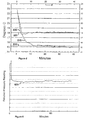
- Figure 5 shows crucible temperature vs. time for two different injection chemicals in accordance with the invention.
- the examples show the crucible temperature stabilizing within about 10-12 minutes after beginning to cool the crucible with the Peltier element.
- the temperature controller set at 18° Celcius as indicated by line 500, the temperature drops from ambient 22+° Celcius to just below 18° Celcius in about 4 minutes, and then is maintained within a narrow range about 18° Celcius as indicated by trace 505.
- the temperature controller set at 15.2° Celcius as indicated by line 510 the temperature drops from ambient 22+° Celcius to about 15.2° Celcius in about 12 minutes, and then is maintained within a narrow range about 15.2° Celcius as indicated by trace 515.
- the temperature can be kept stable to within about ⁇ 1° Celcius with a temperature control system in accordance with the invention.
- Figure 6 shows relative pressure vs. time for an injection chemical in a thermoelectrically cooled crucible in accordance with the invention.
- trace 600 relative pressure within the crucible stabilizes within minutes of beginning to cool the crucible with the Peltier element, and remains stabilized within a narrow range over an extended period of operation. Stabilized vapor pressure at a desired level below that possible at room temperature, or above that possible at room temperature, is achieved with the system described.
- a gas-assisted FIB system such as the IDS P2X FIBstation, available commercially from Schlumberger Technologies, Inc., of San Jose, California, may be readily modified in accordance with the invention.
- Thermoelectric cooling of the crucible allows the elimination of an aperture in the gas-injection flow line when using chemicals which have inconveniently high vapor pressures at conventional working temperatures.
- vapor pressure of the material is lowered so as to decrease the effective partial pressure of the material in the vacuum chamber where the sample is located.
- Thermoelectric cooling allows control of the vapor pressure of the material as opposed to controlling the flow rate with an aperture. This results in a more direct control over the flow rate and over the vacuum chamber total pressure.
- the vacuum chamber total pressure is most easily monitored -- the chamber pressure is noted before commencing injection-gas flow and again after injection-gas flow has stabilized.
- Eliminating a flow-restriction aperture avoids the possibility of the aperture becoming corroded and/or blocked by the sometimes corrosive gases passing through. Any foreign particle larger than the few tens of microns diameter of the aperture can completely block the flow of gas to the injection needle. Avoiding use of a flow-restriction aperture can thus reduce system downtime and related costs. Controlling the system pressure with thermoelectric cooling also allows for more efficient use of the chemical since only as much as is needed is released from the crucible.
- thermoelectric cell can also be used for heating the crucible by simply reversing the direction of electrical current flow through the device relative to that used in the cooling mode. This benefit would work as well as resistive heating with the added benefit of having a multitude of crucibles of all the same construction so that different chemicals with radically different vapor pressures would all still be able to use the same type crucible design.
Landscapes
- Chemical & Material Sciences (AREA)
- Engineering & Computer Science (AREA)
- Mechanical Engineering (AREA)
- Chemical Kinetics & Catalysis (AREA)
- Organic Chemistry (AREA)
- Physics & Mathematics (AREA)
- Metallurgy (AREA)
- Materials Engineering (AREA)
- General Engineering & Computer Science (AREA)
- Analytical Chemistry (AREA)
- Plasma & Fusion (AREA)
- Thermal Sciences (AREA)
- General Chemical & Material Sciences (AREA)
- Sampling And Sample Adjustment (AREA)
- Physical Deposition Of Substances That Are Components Of Semiconductor Devices (AREA)
- Tests Of Electronic Circuits (AREA)
- Control Of Temperature (AREA)
Description
- The present invention relates to methods and apparatus for conducting focused-ion-beam (FIB) operations on integrated circuits.
- Conducting operations on an IC device for failure analysis, debug, and even repair, has become commonplace. Typically, a FIB is used to mill away material to expose a conductor and/or to cut a conductor, while introducing a gas or gases to selectively enhance the milling rate of the material to be removed. See, for example, pending U.S. patent application 08/268,790, filed June 30, 1994 of Talbot et al. (US-A-5 616 921). A FIB can also be used to selectively deposit conductive and insulative material by introducing a suitable gas or gases near the working region of the FIB. See, for example, U.S. Patent No. 5,104,684 to Tao et al. and pending U.S. patent application 08/434,548 to Ximen et al (US-A-5 700 526). Systems for performing FIB operations are known in the art, such as the IDS P2X FIBstation, available commercially from Schlumberger Technologies, Inc., of San Jose, California. See also U.S. Patent No. 5,140,164 to Talbot et al.
- Figure 1 shows a schematic diagram of a typical prior-
art system 110 for conducting such operations.System 110 has three main functional elements: a FIBprobe 112, acircuit exerciser 114, and adata processing system 116 which includes adisplay terminal 118. An IC 126 is placed in avacuum chamber 128 of FIBprobe 112.Circuit exerciser 114 may be a conventional IC tester which can repeatedly apply a pattern of test vectors to IC 126 over a bus in response to commands received fromdata processing system 116 overbus 110. The FIB can be aimed at a desired location on the IC in response to commands supplied fromdata processing system 116 overbus 122. A charged particle detector withinFIB probe 112 supplies measurements of the energy of secondary charged particles todata processing system 116 overbus 122.Data processing system 116 may be commanded by an operator to specify the test signal pattern used and the timing of measurements relative to the test signal pattern. - Figure 2 shows a more detailed schematic diagram of such a
FIB system 200. Avacuum chamber 202 evacuated bypumps 204 encloses aFIB column 206, aspecimen stage 208. for holding aspecimen 210 such as an IC device to be repaired, adetector 212, and agas injector 214.Column 206 includes anion source 216, and ion-optical elements 218 for controlling alignment and deflection of anion beam 220.Detector 212 may comprise ascintillator 222 and a photo-multiplier tube 224 for detectingsecondary electrons 226 emitted whenion beam 220 impinges onspecimen 210. - The system includes a
workstation 230 having a processor unit (CPU) 234, amonitor 236 and input/output (I/O)devices 238 such as a keyboard and/or mouse.Workstation 230 is linked by abus 240 to asystem control unit 242 comprising a control CPU, an image processor and image memory.System control unit 242 communicates via abus 244 with a vacuum-pumps control 246 for controllingvacuum pumps 204, withgas injector control 248 for controllinggas injector 214, with FIB high-voltage control 250 for controllingion source 216, with FIB alignment &deflection control 252 for controlling ionoptical elements 218, withimaging electronics 254 which receive a detector signal fromdetector 212, and with specimen-stage control 256 for controllingspecimen stage 208 to positionspecimen 210.System control unit 242 preferably receives image information fromimaging electronics 254 and supplies beam control information to FIB alignment anddeflection control 252. - In operation, a
specimen 210 is placed invacuum chamber 202.Chamber 202 is evacuated. Under control ofsystem control unit 242, FIB 220 is scanned over a selected region of the specimen to mill away material from the surface ofspecimen 210 and/or to deposit material on the surface ofspecimen 210. During milling and deposition, a suitable gas is injected at the surface ofspecimen 210 fromgas injector 214. In the Schlumberger IDS P2X FIBstation, for example, separate crucibles are provided for storage of multiple gas-producing compounds. The crucibles supply gas to an injector needle via a controllable manifold (not illustrated) so that rapid switch-over from one gas to another is possible upon command from the system control unit. - Figure 3 schematically illustrates a
portion 300 of prior-art gas injector 214 in partial cross-sectional view. A stainless-steel crucible 305 contains a solid orliquid chemical 310 to be used as a source for injection gas. Atemperature controller 315 regulates temperature ofcrucible 305 by monitoring the output of atemperature sensor 320 and controlling apower supply 325 which powers aresistive heater 330.Temperature controller 315 is set by command fromsystem control unit 242 so that a constant temperature suitable for the injection chemical is maintained in the crucible. Injection-chemical vapor passes from the crucible to amanifold 335 via first andsecond tube portions connection 350, through a valve 355 which is controlled bygas injector control 248, and through third andfourth tube portions connection 370. An O-ring seal 372 betweencrucible 305 and a flange 374 oftube portion 340 prevents unwanted release of vapor. Manifold 335 has additional input lines such aslines output line 385 for supplying vapors to aninjector needle 390. Aresistive heater 392 powered bypower supply 325 under control oftemperature controller 315 maintains the temperature of vapor as it passes fromcrucible 305 to manifold 335.Insulation 394 is provided to help maintain an even temperature. The temperature of the chemical is thus maintained by a simple closed-loop control system in a range of about 10° - 60° Celcius. - When a compound to be used for gas injection has a vapor pressure that is too high for the range of temperatures achievable by resistive heating of the crucible, a
restrictive aperture 396 is optionally provided intube portion 340 to reduce the gas flow rate and allow the crucible temperature to be raised into the achievable range.Aperture 396 is typically mounted immediately abovecrucible 305, upstream of valve 355, in order to limit the volume of vapor contained behind the aperture and thus reduce the crucible pump-down time. - The use of a flow-restriction aperture with such chemicals has a number of disadvantages. First, the aperture can clog and is not easily removed for cleaning. Second, pressure builds up in the flow passage when vapor flow is shut off. When vapor flow is restarted, pressure behind the aperture is high and the flow rate is higher than intended. The pressure must be bled down either through the aperture or through another flow path (not illustrated) to an acceptable level before gas injection at a stabilized flow rate can occur. If bleed-off is through the injection needle, the injection chemical is at a higher-than-intended partial pressure within the vacuum chamber and must be pumped out. Third, vapor is wasted which reduces the lifetime of a prepared crucible. More frequent crucible replacement increases operating cost and system downtime.
- Document EP-A-221 184 also discloses a compound vapour spray nozzle for a mask repairing apparatus having a crucible heated by a resistive heater.
- Improved methods and apparatus for controlling flow of injection-chemical vapors are desired.
- The present invention relates to an apparatus as claimed in
claim 1 and to a method as claimed in claim 9. - Preferred embodiments of the invention provide for thermoelectric cooling or heating of the crucible with a Peltier element. This can eliminate for some injection chemicals the need for a flow-restriction aperture. For other injection chemicals it can avoid some of the disadvantages otherwise encountered with the use of a flow-restriction aperture. Thermoelectric cooling can overcome difficulties associated with an aperture and can make possible the vapor-injection of chemicals which are otherwise impractical for use in FIB operations.
- In a preferred form, the invention provides apparatus for supplying a jet of chemical vapor at a substantially constant rate, comprising a crucible for containing a quantity of chemical, a hollow needle, a flow path from the crucible to the hollow needle, a Peltier element in thermal communication with the crucible; and a temperature control circuit responsive to temperature in the crucible for powering the Peltier element so as to maintain temperature of the crucible substantially constant. The temperature control circuit powers the Peltier element so as to maintain temperature of the crucible below (or above) ambient temperature. The temperature control circuit may comprise a temperature sensor responsive to temperature in the crucible, a temperature controller responsive to the temperature sensor, and a power supply responsive to the temperature controller for powering the Peltier element. A heat sink in thermal communication with the Peltier element improves heat transfer. A fan for moving ambient air over the heat sink may also be used to enhance heat transfer. A controllable valve is provided in the flow path for starting and stopping flow of vapor to the hollow needle. A heating element may be provided in thermal communication with the flow path, along with a second temperature control circuit for powering the heating element so as to maintain temperature of the flow path substantially constant. The flow path preferably includes a thermally-insulative portion which provides a thermal break between the crucible and other portions of the flow path.
- The chemical-vapor supplying apparatus can be used as a subsystem of an apparatus for modifying an integrated circuit specimen which further comprises a vacuum chamber and an ion-optical column for directing a focused ion beam at an integrated circuit specimen within the vacuum chamber. Control of vapor pressure, and thus flow rate, offers improved control over FIB processing of integrated circuit specimens.
- Preferred methods in accordance with the invention comprise supplying a jet of chemical vapor at a substantially constant rate by storing a quantity of chemical in a crucible in thermal communication with a Peltier element, placing the crucible in communication with a hollow needle along a flow path from the crucible to the hollow needle, monitoring temperature in the crucible with a temperature sensor, and powering the Peltier element so as to maintain temperature of the crucible substantially constant. Ambient air may be passed over a heat sink in thermal communication with the Peltier element. The Peltier element is powered by supplying a current to the Peltier element so as to cool the crucible below ambient temperature or to warm the crucible above ambient temperature.
- These and other features of the invention will become apparent to those of skill in the art from the following description and the accompanying drawing figures.
-
- Figure 1 shows a schematic diagram of a typical prior-art FIB system;
- Figure 2 shows a more detailed schematic diagram of a prior-art FIB system;
- Figure 3 schematically illustrates a portion of a prior-art gas injector in partial sectional view;
- Figure 4 schematically illustrates a gas injector subsystem embodiment in accordance with the invention in partial sectional view;
- Figure 5 shows crucible temperature vs. time for two different injection chemicals in accordance with the invention; and
- Figure 6 shows relative pressure vs. time for an injection chemical in a thermoelectrically cooled crucible in accordance with the invention.
-
- Figure 4 schematically illustrates a gas
injector subsystem embodiment 400 in accordance with the invention in partial sectional view. A stainless-steel crucible 405 contains a chemical 410 to be used as a source for injection gas. Atemperature controller 415 regulates temperature ofcrucible 405 by monitoring the output of atemperature sensor 420 and controlling apower supply 425 which powers a Peltier element (thermoelectric device) 430. Temperature controller is set by command fromsystem control unit 248 so that a constant temperature suitable for the injection chemical is maintained in the crucible.Peltier element 430 is affixed tocrucible 405 so as to provide a good heat conduction path between the two, such as with astrip 435 of double-sided thermally-conducting adhesive tape. Aheat sink 440 is affixed to the opposite face ofPeltier element 430 so as to provide a good heat-conduction path between the two, such as with astrip 445 of double-sided thermally-conducting adhesive tape. It is important to have thermally-conducting interfaces so as to avoid compromising efficiency of the system. Afan 450, which may also be powered bypower supply 425 under control oftemperature controller 415, is optionally provided to improve convective heat transfer betweenheat sink 440 and the atmosphere. - Any of a wide variety of commercially available products may be used for the
Peltier element 430, forheat sink 440 and for double-sided thermally-conducting adhesive tape strips 435 and 445. For example,Peltier element 430 can be a thermoelectric cooling element part number CP-1.0-127-06L, available from Melcor, Trenton, NJ, which can pump a maximum of 25 watts running at up to 15 volts and 3 amps. - A
convenient heat sink 440 for this application is the type intended for cooling of 80486 or Pentium microprocessor chips. These often are provided with double-sided, thermally-conducting adhesive tape which allows easy and efficient mounting toPeltier element 430. The same kind of adhesive tape can also be used to matePeltier element 430 to the bottom ofcrucible 405 making assembly easy.Heat sink 440 can be an Aavid Engineering model 3302 heat sink. Alternatively, a heat sink and fan combination can be used, such as Sanyo Denki Co. part number 109P4405H8026. Double-sided thermally-conducting adhesive tape is available from Aavid Engineering under part number D037302385B. -
Temperature controller 415 can be an Auto-Tune PID (proportional, integral, derivative) controller part number CN-76000, available from Omega Engineering, Stamford, CT. The temperature controller reads the temperature fromsensor 420 mounted oncrucible 405 and outputs a signal voltage which controls a constant-current power supply capable of providing, for example, up to 1 amp at 5 volts DC. With the arrangement described, temperatures down to zero degrees Celcius are readily achieved with a small fan blowing on the heat sink in a room-temperature ambient environment. The parameters given can be altered when used with different models and makes ofthermoelectric element 430. -
Peltier element 430 can also be used forheating crucible 405 by reversing the flow of current through the Peltier element. The arrangement described has been tested and found to easily lower the crucible temperature to as low as zero degrees Celcius or to raise the crucible temperature to the maximum desirable operating level of 60° Celcius. The operating temperature range can be extended by substituting a stacking of multiple Peltier elements for thesingle Peltier element 440 shown in Figure 4. - When temperature of
crucible 405 is stabilized at a level appropriate for the chemical to be injected, chemical vapor passes fromcrucible 405 to ahollow injection needle 390 via a bore in a thermally-insulatingspacer 455 of Teflon or other suitable material, through first andsecond tube portions connection 470, through avalve 482 which is controlled bygas injector control 248, through third andfourth tube portions connection 488, and via amanifold 335 andsupply line 385. O-ring seal 475 betweenspacer 455 andcrucible 405 and O-ring seal 480 betweenspacer 455 and aflange 478 oftube portion 460 prevent unwanted release of vapor. An optionalflow restriction aperture 478 can be provided if the vapor pressure of a particular chemical to be injected is insufficiently reduced by cooling, making possible the use of injection chemicals which were heretofore impractical due to their high vapor pressures at or above ambient temperature. - A
resistive heater 496 powered bypower supply 494 under control oftemperature controller 490 maintains the temperature of vapor as it passes fromcrucible 405 to the manifold, avoiding condensation of vapor in the flow path. While shownheating valve 482,resistive heating element 496 can be used to heat other portions of the flow path above thermally-insulatingspacer 455 as needed to avoid condensation of vapor.Heating element 496 can, for example, be a plurality of separate heating elements for heating respective segments of the flow path, and/or can be a resistive heating tape. Peltier elements supplied with current to heath the flow path can be substituted for resistive heating elements.Insulation 498, only a portion of which is shown for clarity of illustration, is provided wherever possible to help maintain an even temperature along the vapor flow path by thermally decoupling the assembly from the ambient environment. -
Crucible 405 is a container preferably made of chemically inert material such as stainless steel, mounted for easy removal from the system. Components defining the vapor flow path, such astube portions Spacer 455 is also of chemically inert material, though in this case the material must also be thermally insulative, such as Teflon, so as to thermally isolatecrucible 405 from the rest of the vapor flow path. - Figure 5 shows crucible temperature vs. time for two different injection chemicals in accordance with the invention. The examples show the crucible temperature stabilizing within about 10-12 minutes after beginning to cool the crucible with the Peltier element. With the temperature controller set at 18° Celcius as indicated by
line 500, the temperature drops from ambient 22+° Celcius to just below 18° Celcius in about 4 minutes, and then is maintained within a narrow range about 18° Celcius as indicated bytrace 505. With the temperature controller set at 15.2° Celcius as indicated byline 510, the temperature drops from ambient 22+° Celcius to about 15.2° Celcius in about 12 minutes, and then is maintained within a narrow range about 15.2° Celcius as indicated bytrace 515. In general, the temperature can be kept stable to within about ±1° Celcius with a temperature control system in accordance with the invention. - Figure 6 shows relative pressure vs. time for an injection chemical in a thermoelectrically cooled crucible in accordance with the invention. As shown by
trace 600, relative pressure within the crucible stabilizes within minutes of beginning to cool the crucible with the Peltier element, and remains stabilized within a narrow range over an extended period of operation. Stabilized vapor pressure at a desired level below that possible at room temperature, or above that possible at room temperature, is achieved with the system described. - A gas-assisted FIB system such as the IDS P2X FIBstation, available commercially from Schlumberger Technologies, Inc., of San Jose, California, may be readily modified in accordance with the invention.
- Thermoelectric cooling of the crucible allows the elimination of an aperture in the gas-injection flow line when using chemicals which have inconveniently high vapor pressures at conventional working temperatures. By lowering the temperature of the compound below room temperature (down to as low as 0° Celcius), vapor pressure of the material is lowered so as to decrease the effective partial pressure of the material in the vacuum chamber where the sample is located. Thermoelectric cooling allows control of the vapor pressure of the material as opposed to controlling the flow rate with an aperture. This results in a more direct control over the flow rate and over the vacuum chamber total pressure. In operation of a FIB system, the vacuum chamber total pressure is most easily monitored -- the chamber pressure is noted before commencing injection-gas flow and again after injection-gas flow has stabilized.
- Eliminating a flow-restriction aperture avoids the possibility of the aperture becoming corroded and/or blocked by the sometimes corrosive gases passing through. Any foreign particle larger than the few tens of microns diameter of the aperture can completely block the flow of gas to the injection needle. Avoiding use of a flow-restriction aperture can thus reduce system downtime and related costs. Controlling the system pressure with thermoelectric cooling also allows for more efficient use of the chemical since only as much as is needed is released from the crucible.
- When there is an aperture in the system pressure builds up greatly behind the valve when that gas is not being used and needs to be vented off before that gas can be used again. Since this built up pressure needs to be released through the aperture this results in extra time required before being able to use that gas and might also result in the need for an auxiliary pump-around valve to permit pumping out this built up gas quickly by going around the aperture through another pipe and valve. This built up gas also represents a waste of chemical which would therefore require more frequent refilling of the crucible as the material is used up more quickly.
- For compounds that do require heating even without an aperture a thermoelectric cell can also be used for heating the crucible by simply reversing the direction of electrical current flow through the device relative to that used in the cooling mode. This benefit would work as well as resistive heating with the added benefit of having a multitude of crucibles of all the same construction so that different chemicals with radically different vapor pressures would all still be able to use the same type crucible design.
- Those of skill in the art will recognize that these and other modifications can be made within the spirit and scope of the invention as defined in the claims which follow.
Claims (20)
- Apparatus for supplying a jet of chemical vapor at a substantially constant rate, comprising:a. a crucible (405) for containing a quantity of chemical (410),b. a hollow needle (390);c. a flow path (455, 460, 470, 482, 484, 486) from the crucible to the hollow needle;d. a Peltier element (430) in thermal communication with the crucible; ande. a temperature control circuit (415, 420, 425) responsive to temperature in the crucible for powering the Peltier element so as to maintain temperature of the crucible substantially constant.
- The apparatus of claim 1, wherein the temperature control circuit powers the Peltier element so as to maintain temperature of the crucible below ambient temperature.
- The apparatus of claim 2, wherein the temperature control circuit comprises a temperature sensor (420) responsive to temperature in the crucible, a temperature controller (415) responsive to the temperature sensor, and a power supply (425) responsive to the temperature controller for powering the Peltier element.
- The apparatus of claim 1, further comprising a heat sink (440) in thermal communication with the Peltier element.
- The apparatus of claim 4, further comprising a fan (450) for moving ambient air over the heat sink.
- The apparatus of claim 1, further comprising a controllable valve 482 for starting and stopping flow of vapor to the hollow needle.
- The apparatus of claim 1, further comprising a heating element (496) in thermal communication with the flow path, and a second temperature control circuit (490, 492, 494) for powering the heating element so as to maintain temperature of the flow path substantially constant.
- The apparatus of claim 1, wherein the flow path includes a thermally-insulative portion (455) which provides a thermal break between the crucible and other portions of the flow path.
- A method of supplying a jet of chemical vapor at a substantially constant rate, comprising:a. storing a quantity of chemical (410) in a crucible (405) in thermal communication with a Peltier element (430);b. placing the crucible in communication with a hollow needle (390) along a flow path (455, 460, 470, 482, 484, 486) from the crucible to the hollow needle;c. monitoring temperature in the crucible with a temperature sensor (420); andd. powering the Peltier element so as to maintain temperature of the crucible substantially constant.
- The method of claim 9, further comprising the step of passing ambient an over a heat sink in thermal communication with the Peltier element.
- The method of claim 9, wherein powering the Peltier element comprises supplying a current to the Peltier element so as to cool the crucible below ambient temperature.
- The method of claim 9, wherein powering the Peltier element comprises supplying a current to the Peltier element so as to warm the crucible above ambient temperature.
- Apparatus for modifying an integrated circuit specimen, comprising:a. a vacuum chamber (202);b. an ion-optical column (206) for directing a focused ion beam at an integrated circuit specimen (210) within the vacuum chamber; andc. a gas injector subsystem (214) includingi. a crucible (405) for containing a quantity of chemical (410);ii. a hollow needle (390);iii. a flow path (455, 460, 470, 482, 484, 486) from the crucible to the hollow needle;iv. a Peltier element (430) in thermal communication with the crucible; andv. a temperature control circuit (415, 420, 425) responsive to temperature in the crucible for powering the Peltier element so as to maintain temperature of the crucible substantially constant.
- The apparatus of claim 13, wherein the temperature control circuit powers the Peltier element so as to maintain temperature of the crucible below ambient temperature.
- The apparatus of claim 14, wherein the temperature control circuit comprises a temperature sensor (420) responsive to temperature in the crucible, a temperature controller (415) responsive to the temperature sensor, and a power supply (425) responsive to the temperature controller for powering the Peltier element.
- The apparatus of claim 13, further comprising a heat sink (440) in thermal communication with the Peltier element.
- The apparatus of claim 16, further comprising a fan (450) for moving ambient air over the heat sink.
- The apparatus of claim 13, further comprising a controllable valve (482) for starting and stopping flow of vapor to the hollow needle.
- The apparatus of claim 13, further comprising a heating element (496) in thermal communication with the flow path, and a second temperature control circuit (490, 492, 494) for powering the heating element so as to maintain temperature of the flow path substantially constant.
- The apparatus of claim 14, wherein the flow path includes a thermally-insulative portion (455) which provides a thermal break between the crucible and other portions of the flow path.
Applications Claiming Priority (2)
| Application Number | Priority Date | Filing Date | Title |
|---|---|---|---|
| US08/734,746 US5747818A (en) | 1996-10-21 | 1996-10-21 | Thermoelectric cooling in gas-assisted FIB system |
| US734746 | 1996-10-21 |
Publications (3)
| Publication Number | Publication Date |
|---|---|
| EP0838836A2 EP0838836A2 (en) | 1998-04-29 |
| EP0838836A3 EP0838836A3 (en) | 2000-03-08 |
| EP0838836B1 true EP0838836B1 (en) | 2003-09-03 |
Family
ID=24952922
Family Applications (1)
| Application Number | Title | Priority Date | Filing Date |
|---|---|---|---|
| EP97402304A Expired - Lifetime EP0838836B1 (en) | 1996-10-21 | 1997-10-01 | Thermoelectric cooling in gas-assisted focused ion beam (FIB) system |
Country Status (4)
| Country | Link |
|---|---|
| US (1) | US5747818A (en) |
| EP (1) | EP0838836B1 (en) |
| JP (1) | JPH10198438A (en) |
| DE (1) | DE69724549T2 (en) |
Cited By (1)
| Publication number | Priority date | Publication date | Assignee | Title |
|---|---|---|---|---|
| CN107543366A (en) * | 2017-10-11 | 2018-01-05 | 浙江海洋大学 | A kind of temperature regulation system of vacuum tank at lower voltages |
Families Citing this family (13)
| Publication number | Priority date | Publication date | Assignee | Title |
|---|---|---|---|---|
| JP3494889B2 (en) * | 1998-06-03 | 2004-02-09 | セイコーインスツルメンツ株式会社 | Focused ion beam processing equipment |
| EP1040464A2 (en) * | 1998-06-25 | 2000-10-04 | Koninklijke Philips Electronics N.V. | Display device with temperature-stabilizing means |
| IL138710A0 (en) * | 1999-10-15 | 2001-10-31 | Newman Martin H | Atomically sharp edge cutting blades and method for making same |
| DE19952331C1 (en) | 1999-10-29 | 2001-08-30 | Schott Spezialglas Gmbh | Method and device for quickly cutting a workpiece from brittle material using laser beams |
| JP2003031050A (en) * | 2001-07-16 | 2003-01-31 | Nec Corp | Superconductor thin film of copper oxide containing mercury, manufacturing device and manufacturing method therefor |
| US6824655B2 (en) | 2001-08-27 | 2004-11-30 | Credence Systems Corporation | Process for charged particle beam micro-machining of copper |
| DE10208043B4 (en) * | 2002-02-25 | 2011-01-13 | Carl Zeiss Nts Gmbh | Material processing system and material processing methods |
| US20050103272A1 (en) * | 2002-02-25 | 2005-05-19 | Leo Elektronenmikroskopie Gmbh | Material processing system and method |
| US7060196B2 (en) * | 2003-10-03 | 2006-06-13 | Credence Systems Corporation | FIB milling of copper over organic dielectrics |
| KR20050040434A (en) * | 2003-10-28 | 2005-05-03 | 삼성전자주식회사 | Specimen cooling system of focused ion beam apparatus |
| EP1774538A4 (en) * | 2004-07-29 | 2012-06-06 | Omniprobe Inc | Multiple gas injection system for charged particle beam instruments |
| US9928983B2 (en) * | 2016-06-30 | 2018-03-27 | Varian Semiconductor Equipment Associates, Inc. | Vaporizer for ion source |
| CN107895635A (en) * | 2017-11-09 | 2018-04-10 | 乐志胜 | A kind of dust-proof auxiliary heat-radiating device of transformer |
Family Cites Families (7)
| Publication number | Priority date | Publication date | Assignee | Title |
|---|---|---|---|---|
| US4930439A (en) * | 1984-06-26 | 1990-06-05 | Seiko Instruments Inc. | Mask-repairing device |
| EP0221184B1 (en) * | 1984-06-26 | 1990-08-16 | Seiko Instruments Inc. | Mask repairing apparatus |
| DE3672378D1 (en) * | 1985-04-23 | 1990-08-09 | Seiko Instr Inc | DEVICE FOR DEPOSITING AN ELECTRICALLY CONDUCTIVE AND / OR NON-CONDUCTIVE MATERIAL ON AN OBJECT. |
| US5104684A (en) * | 1990-05-25 | 1992-04-14 | Massachusetts Institute Of Technology | Ion beam induced deposition of metals |
| US5140164A (en) * | 1991-01-14 | 1992-08-18 | Schlumberger Technologies, Inc. | Ic modification with focused ion beam system |
| JP3310136B2 (en) * | 1994-09-17 | 2002-07-29 | 株式会社東芝 | Charged beam device |
| US5700526A (en) * | 1995-05-04 | 1997-12-23 | Schlumberger Technologies Inc. | Insulator deposition using focused ion beam |
-
1996
- 1996-10-21 US US08/734,746 patent/US5747818A/en not_active Expired - Fee Related
-
1997
- 1997-10-01 EP EP97402304A patent/EP0838836B1/en not_active Expired - Lifetime
- 1997-10-01 DE DE69724549T patent/DE69724549T2/en not_active Expired - Lifetime
- 1997-10-21 JP JP9288580A patent/JPH10198438A/en active Pending
Cited By (1)
| Publication number | Priority date | Publication date | Assignee | Title |
|---|---|---|---|---|
| CN107543366A (en) * | 2017-10-11 | 2018-01-05 | 浙江海洋大学 | A kind of temperature regulation system of vacuum tank at lower voltages |
Also Published As
| Publication number | Publication date |
|---|---|
| JPH10198438A (en) | 1998-07-31 |
| US5747818A (en) | 1998-05-05 |
| DE69724549D1 (en) | 2003-10-09 |
| EP0838836A2 (en) | 1998-04-29 |
| DE69724549T2 (en) | 2004-07-01 |
| EP0838836A3 (en) | 2000-03-08 |
Similar Documents
| Publication | Publication Date | Title |
|---|---|---|
| US5747818A (en) | Thermoelectric cooling in gas-assisted FIB system | |
| US8178444B2 (en) | Substrate processing method and substrate processing apparatus | |
| US10157724B2 (en) | Electron scanning microscope and image generation method | |
| US4638209A (en) | Ion beam generating apparatus | |
| JP4490704B2 (en) | Plasma processing method | |
| US20090224788A1 (en) | Apparatus for detecting defect | |
| US20090133717A1 (en) | Ceramic sprayed member-cleaning method, program for implementing the method, storage medium storing the program, and ceramic sprayed member | |
| US11189458B2 (en) | Cryo nanomanipulator probe with integrated gas injection | |
| EP3671811A1 (en) | Methods and apparatus for active heat transfer management in ion sources | |
| US8648316B2 (en) | Apparatus for cooling samples during ion beam preparation | |
| JP3457855B2 (en) | FIB assist gas introduction device | |
| JP2009505441A (en) | Non-intrusive plasma monitoring system for detecting and preventing arcs in blanket CVD films | |
| US20250283220A1 (en) | Method and apparatus for precursor gas injection | |
| US20100068408A1 (en) | Methods for electron-beam induced deposition of material inside energetic-beam microscopes | |
| JP7750959B2 (en) | Isothermal ion source with auxiliary heater | |
| JP2001083121A (en) | Atmospheric pressure ionization mass spectrometer | |
| JP5465835B2 (en) | Plasma processing apparatus and plasma processing method | |
| KR100228517B1 (en) | Method of stabilizing operation for a liquid metal ion source | |
| JP2008107014A (en) | Cooling device, and cooling method of chamber space for device test | |
| CN113363126B (en) | Particle beam system, method of operating a particle beam system, and computer program product | |
| JP2006210948A (en) | Plasma processing equipment | |
| JPH09172053A (en) | Semiconductor device manufacturing method and semiconductor device manufacturing apparatus | |
| US20230102972A1 (en) | Active temperature control for rf window in immersed antenna source | |
| US20250118525A1 (en) | Particle beam system with cooling system | |
| Leavitt et al. | Ultrahigh vacuum surface science chamber with integral scanning tunneling microscope |
Legal Events
| Date | Code | Title | Description |
|---|---|---|---|
| PUAI | Public reference made under article 153(3) epc to a published international application that has entered the european phase |
Free format text: ORIGINAL CODE: 0009012 |
|
| AK | Designated contracting states |
Kind code of ref document: A2 Designated state(s): DE FR GB |
|
| AX | Request for extension of the european patent |
Free format text: AL;LT;LV;RO;SI |
|
| PUAL | Search report despatched |
Free format text: ORIGINAL CODE: 0009013 |
|
| AK | Designated contracting states |
Kind code of ref document: A3 Designated state(s): AT BE CH DE DK ES FI FR GB GR IE IT LI LU MC NL PT SE |
|
| AX | Request for extension of the european patent |
Free format text: AL;LT;LV;RO;SI |
|
| RIC1 | Information provided on ipc code assigned before grant |
Free format text: 7H 01J 37/305 A, 7H 01J 37/30 B, 7H 01J 37/304 B, 7C 23C 16/04 B, 7H 01L 21/768 B, 7C 23C 14/22 B, 7F 25B 21/04 B |
|
| 17P | Request for examination filed |
Effective date: 20000426 |
|
| AKX | Designation fees paid |
Free format text: DE FR GB |
|
| GRAH | Despatch of communication of intention to grant a patent |
Free format text: ORIGINAL CODE: EPIDOS IGRA |
|
| GRAS | Grant fee paid |
Free format text: ORIGINAL CODE: EPIDOSNIGR3 |
|
| GRAA | (expected) grant |
Free format text: ORIGINAL CODE: 0009210 |
|
| AK | Designated contracting states |
Kind code of ref document: B1 Designated state(s): DE FR GB |
|
| REG | Reference to a national code |
Ref country code: GB Ref legal event code: FG4D |
|
| REF | Corresponds to: |
Ref document number: 69724549 Country of ref document: DE Date of ref document: 20031009 Kind code of ref document: P |
|
| ET | Fr: translation filed | ||
| PLBE | No opposition filed within time limit |
Free format text: ORIGINAL CODE: 0009261 |
|
| STAA | Information on the status of an ep patent application or granted ep patent |
Free format text: STATUS: NO OPPOSITION FILED WITHIN TIME LIMIT |
|
| 26N | No opposition filed |
Effective date: 20040604 |
|
| REG | Reference to a national code |
Ref country code: GB Ref legal event code: 732E |
|
| REG | Reference to a national code |
Ref country code: FR Ref legal event code: TP Ref country code: FR Ref legal event code: CD Ref country code: FR Ref legal event code: CA |
|
| PGFP | Annual fee paid to national office [announced via postgrant information from national office to epo] |
Ref country code: GB Payment date: 20060915 Year of fee payment: 10 |
|
| GBPC | Gb: european patent ceased through non-payment of renewal fee |
Effective date: 20071001 |
|
| PG25 | Lapsed in a contracting state [announced via postgrant information from national office to epo] |
Ref country code: GB Free format text: LAPSE BECAUSE OF NON-PAYMENT OF DUE FEES Effective date: 20071001 |
|
| PGFP | Annual fee paid to national office [announced via postgrant information from national office to epo] |
Ref country code: FR Payment date: 20081014 Year of fee payment: 12 |
|
| PGFP | Annual fee paid to national office [announced via postgrant information from national office to epo] |
Ref country code: DE Payment date: 20090923 Year of fee payment: 13 |
|
| REG | Reference to a national code |
Ref country code: FR Ref legal event code: ST Effective date: 20100630 |
|
| PG25 | Lapsed in a contracting state [announced via postgrant information from national office to epo] |
Ref country code: FR Free format text: LAPSE BECAUSE OF NON-PAYMENT OF DUE FEES Effective date: 20091102 |
|
| REG | Reference to a national code |
Ref country code: DE Ref legal event code: R119 Ref document number: 69724549 Country of ref document: DE Effective date: 20110502 |
|
| PG25 | Lapsed in a contracting state [announced via postgrant information from national office to epo] |
Ref country code: DE Free format text: LAPSE BECAUSE OF NON-PAYMENT OF DUE FEES Effective date: 20110502 |