EP0838741B1 - Steuerungsgerät für ein Schmiersystem - Google Patents
Steuerungsgerät für ein Schmiersystem Download PDFInfo
- Publication number
- EP0838741B1 EP0838741B1 EP97117190A EP97117190A EP0838741B1 EP 0838741 B1 EP0838741 B1 EP 0838741B1 EP 97117190 A EP97117190 A EP 97117190A EP 97117190 A EP97117190 A EP 97117190A EP 0838741 B1 EP0838741 B1 EP 0838741B1
- Authority
- EP
- European Patent Office
- Prior art keywords
- configuration
- control unit
- memorizing
- selection
- control
- Prior art date
- Legal status (The legal status is an assumption and is not a legal conclusion. Google has not performed a legal analysis and makes no representation as to the accuracy of the status listed.)
- Expired - Lifetime
Links
Images

Classifications
-
- G—PHYSICS
- G05—CONTROLLING; REGULATING
- G05B—CONTROL OR REGULATING SYSTEMS IN GENERAL; FUNCTIONAL ELEMENTS OF SUCH SYSTEMS; MONITORING OR TESTING ARRANGEMENTS FOR SUCH SYSTEMS OR ELEMENTS
- G05B19/00—Program-control systems
- G05B19/02—Program-control systems electric
- G05B19/04—Program control other than numerical control, i.e. in sequence controllers or logic controllers
- G05B19/042—Program control other than numerical control, i.e. in sequence controllers or logic controllers using digital processors
- G05B19/0426—Programming the control sequence
Definitions
- This invention relates to a control device for a lubrication system in accordance with the introduction to the main claim.
- control device of the present invention is arranged to control the system pumping unit or units and to monitor the fluid flow within the system.
- the pumping unit can comprise pumps controlled by means of a constant electrical signal (for example electric pumps) or pumps controlled by means of pulse signals (for example single-acting pneumatic pumps).
- the working and rest cycle of the system pumps is controlled, according to the type of pump, by a timer or a pulse counter.
- the fluid flow within the system can be monitored, for example, via a pressure switch or the like provided in the main line of a valve arrangement, or by a switch provided in a progressive distributor.
- control devices have a control unit comprising selection and display means which enable a particular desired operating configuration for the pumping members to be set and the lubricant fluid flow within the system to be monitored.
- selection and display means For example, the following can be programmed via the selection and display means: type of pump and/or sensors used, minutes and seconds of a pump working cycle, hours and minutes of the rest cycle, number of cycles to be effected, and alarm values for certain characteristic parameters of the fluid, such as pressure or fluid flow rate.
- Known systems generally comprise a control device at each system pumping unit.
- a system therefore often comprises a plurality of mutually independent control devices.
- the problem is even more acute when the producer of the systems has to configure a plurality of systems for example in the same identical manner. If for example he has to configure 50 systems (with 50 control devices) he has to manually perform the same configuration operation for each control device, ie 50 times.
- An object of the present invention is to provide a control device for a lubricant fluid distribution system which simplifies and accelerates the operations involved in selecting a particular system operating configuration, in particular when the same configuration has to be repeated for a plurality of control devices.
- US-5,344,044 A shows an injection system for blending an additive into a main fluid flow stream at a controlled rate.
- This unrelated art comprises a control unit for its own control.
- the control unit comprises a microcontroller to control various system functions such as opening and closing of valves, and memorizing means for memorizing a desired operating configuration.
- the control unit may be remotely controlled by a hand held remote transmitter and communication therebetween is based on electromagnetic energy, e.g. infrared. Based on the information received the control unit invokes a control program.
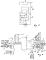
- a control device is formed from two mutually separate distinct components, namely a control unit 1 to be positioned within the system at the pump to be controlled and at the relative fluid monitoring members, and a selection member 2 by means of which a working configuration selected by the user can be remotely fed.
- control unit 1 comprises a central processing member 3, preferably of microprocessor type, comprising a memory 3A, and connected to a display member 4 and to a keypad 5 for selecting a desired configuration, to an alarm member (for example an LED), to a pump 6 to be controlled, and to one or more sensors 8 arranged to measure, along a line of the system, determined characteristics of the fluid, such as a minimum fluid level, the fluid flow rate and/or its pressure.
- a central processing member 3 preferably of microprocessor type, comprising a memory 3A, and connected to a display member 4 and to a keypad 5 for selecting a desired configuration, to an alarm member (for example an LED), to a pump 6 to be controlled, and to one or more sensors 8 arranged to measure, along a line of the system, determined characteristics of the fluid, such as a minimum fluid level, the fluid flow rate and/or its pressure.
- Figure 1 illustrates the control panel of the unit 1, showing the keys 5 and the display 4 for selecting the desired configuration, a key 16 for zeroing or resetting the memorized configuration, and a series of further display lights or LEDs 17A-E, indicating respectively the active or rest state of the pump controlled by the device (17A, B), working cycle control (17C), pulse counting (17D), and the device "on" or "off” state (17E).
- the keypad 5 and display 4 are used to select the component to be "configured", for example an electric pump; then again using the keypad 5 the pump working and rest times and switch-on times are set.
- the limiting values for the controlled fluid parameters within the system section controlled by the device are then set.
- the selected configuration is memorized in the memory 3A.
- the handling of the selection and memorizing operations is preferably done by a conventional program, also for example memorized in the memory 3A, and executted by the central processing member 3.
- a supervising program also for example memorized in the memory 3A and executed by the central processing member 3, activates the pump within the selected time intervals and monitors the fluid parameters selected, to activate the alarm 7 when these parameters are outside those set according to the invention.
- the particular configuration to be memorized can advantageously be selected not only via the keypad 5 provided on the control unit itself, but also by the selection member 2, separate and distinct from the control unit 1, and then fed to this latter for example by infrared rays or radio waves.
- a control unit comprises a receiver member 9, for example of the infrared receiving type, connected to the central processing unit 3.
- a suitable program of conventional type to the expert of the art and therefore not described hereinafter, enables the received configuration to be stored in the memory 3A, this being done on activating the control unit as described in detail hereinafter.
- the selection member 2 is substantially in the form of a usual remote control, and comprises a processing member 13, preferably of microprocessor type, comprising a memory 13A.
- the processor member 13 is connected to a display member 14 and keypad 15 for selecting a desired working configuration, to a key 10 for feeding the selected configuration to the control unit 1, and to a member 11 for remotely transmitting the selected configuration to the unit 1.
- the processing member 13, the memory 13A, the display 14 and the keypad 15 can, for example, be of the same type as that provided in the control unit 1. Consequently the operations to be carried out for selecting a particular working configuration and the operating logic are substantially similar to those already described for the unit 1.
- this configuration can be fed to the control unit 1.
- the members 11, 9 for the remote transmission and reception of the signals relative to a particular configuration can be of any conventional known type suitable for the purpose, for example of infrared or radio wave type.
- the operations required for selecting a preferred configuration are much simplified; in this respect, the configuration can be initially memorized in the member itself without this having to be sited in proximity to the system, then later the selected configuration can be fed to all units requiring it, even by non-expert personnel.
- control unit 1 could be without the selection keypad 5 and display 4.
- the preferred configuration can only be selected via the selection member 2.
- the selection member could be formed in such a manner as to memorize more than one preferred configuration.
- the selection member 2 would have to comprise more than one send key 10, which when pressed would feed one or other of the memorized configurations to the control unit 1.
Landscapes
- Physics & Mathematics (AREA)
- General Physics & Mathematics (AREA)
- Engineering & Computer Science (AREA)
- Automation & Control Theory (AREA)
- Valve Device For Special Equipments (AREA)
- Lubrication Of Internal Combustion Engines (AREA)
- General Details Of Gearings (AREA)
- Selective Calling Equipment (AREA)
- Exposure Of Semiconductors, Excluding Electron Or Ion Beam Exposure (AREA)
Claims (7)
- Steuervorrichtung für ein Schmierungs-System von dem Typ, das eine Steuereinheit (1) aufweist, die mit dem System in Beziehung steht und eine erste Speichereinrichtung (3A) zum Speichern einer gewünschten Betriebskonfiguration von zumindest einem Teil des Systems und eine Einrichtung (3) enthält, um diesen Teil des Systems auf der Basis dieser Konfiguration zu steuern, dadurch gekennzeichnet, daß ein Auswahlbauteil (2) zum Auswählen der gewünschten Konfiguration mittels Auswahleinrichtungen (13, 14, 15) vorgesehen ist, wobei das Auswahlbauteil (2) von der Steuereinheit (1) getrennt und verschieden ist sowie eine zweite Speichereinrichtung (13A), um die ausgewählte Konfiguration zu speichern, und eine Übertragungseinrichtung (11) enthält, um der Steuereinheit (1) die Informationen bezüglich der ausgewählten Konfiguration aus der Ferne zu übermitteln, wobei die Steuereinheit (1) eine Empfangseinrichtung (9) zum Empfangen der Informationen und zum Speichern davon in der ersten Speichereinrichtung (3A) aufweist.
- Vorrichtung nach Anspruch 1, dadurch gekennzeichnet, daß die Übertragungseinrichtung (11) und die Empfangseinrichtung (9) vom Infrarot-Typ sind.
- Vorrichtung nach Anspruch 1, dadurch gekennzeichnet, daß die Übertragungseinrichtung (11) und die Empfangseinrichtung (9) vom Radiowellen-Typ sind.
- Vorrichtung nach Anspruch 1, dadurch gekennzeichnet, daß die Steuereinheit (1) ihre eigenen Einrichtungen (3, 4, 5) zum Auswählen einer gewünschten Konfiguration hat.
- Vorrichtung nach Anspruch 1, dadurch gekennzeichnet, daß die Auswahleinrichtungen (13, 14, 15) und die zweite Speichereinrichtung (13A) des Auswahlbauteils (2) eine Vielzahl von gewünschten, auszuwählenden Konfigurationen ermöglichen, wobei in dem Auswahlbauteil (2) eine Tasteneinrichtung (10) vorgesehen ist, um der Steuereinheit (1) eine oder eine andere dieser Konfigurationen zuzuführen.
- Vorrichtung nach einem der vorhergehenden Ansprüche, dadurch gekennzeichnet, daß die Auswahleinrichtungen (13, 14, 15) des Auswahlbauteils (2) einen Mikroprozessor (13), eine Tastatur (15) und eine Anzeige (14) enthalten.
- Vorrichtung nach einem der vorhergehenden Ansprüche, dadurch gekennzeichnet, daß die eigenen Einrichtungen (3, 4, 5) der Steuereinheit (1) einen Mikroprozessor (3), eine Tastatur (5) und eine Anzeige (4) enthalten.
Applications Claiming Priority (2)
| Application Number | Priority Date | Filing Date | Title |
|---|---|---|---|
| ITMI962205 | 1996-10-24 | ||
| IT96MI002205A ITMI962205A1 (it) | 1996-10-24 | 1996-10-24 | Dispositivo di controllo di un impianto di lubrificazione |
Publications (2)
| Publication Number | Publication Date |
|---|---|
| EP0838741A1 EP0838741A1 (de) | 1998-04-29 |
| EP0838741B1 true EP0838741B1 (de) | 2000-08-23 |
Family
ID=11375084
Family Applications (1)
| Application Number | Title | Priority Date | Filing Date |
|---|---|---|---|
| EP97117190A Expired - Lifetime EP0838741B1 (de) | 1996-10-24 | 1997-10-03 | Steuerungsgerät für ein Schmiersystem |
Country Status (5)
| Country | Link |
|---|---|
| EP (1) | EP0838741B1 (de) |
| AT (1) | ATE195818T1 (de) |
| DE (1) | DE69702887T2 (de) |
| ES (1) | ES2150179T3 (de) |
| IT (1) | ITMI962205A1 (de) |
Family Cites Families (2)
| Publication number | Priority date | Publication date | Assignee | Title |
|---|---|---|---|---|
| US4445168A (en) * | 1981-06-24 | 1984-04-24 | Houdaille Industries, Inc. | Apparatus and method for micro-computer control of lubrication system |
| US5251785A (en) * | 1992-02-06 | 1993-10-12 | The Lubrizol Corporation | Additive injection system and method |
-
1996
- 1996-10-24 IT IT96MI002205A patent/ITMI962205A1/it not_active Application Discontinuation
-
1997
- 1997-10-03 EP EP97117190A patent/EP0838741B1/de not_active Expired - Lifetime
- 1997-10-03 ES ES97117190T patent/ES2150179T3/es not_active Expired - Lifetime
- 1997-10-03 AT AT97117190T patent/ATE195818T1/de not_active IP Right Cessation
- 1997-10-03 DE DE69702887T patent/DE69702887T2/de not_active Expired - Lifetime
Also Published As
| Publication number | Publication date |
|---|---|
| ES2150179T3 (es) | 2000-11-16 |
| DE69702887T2 (de) | 2001-03-01 |
| ITMI962205A1 (it) | 1998-04-24 |
| DE69702887D1 (de) | 2000-09-28 |
| ATE195818T1 (de) | 2000-09-15 |
| EP0838741A1 (de) | 1998-04-29 |
Similar Documents
| Publication | Publication Date | Title |
|---|---|---|
| US5731756A (en) | Universal encrypted radio transmitter for multiple functions | |
| US5781143A (en) | Auto-acquire of transmitter ID by receiver | |
| US6301796B1 (en) | Programmable probe system | |
| US5595342A (en) | Control system | |
| US6901883B2 (en) | Multi-function animal training transmitter | |
| AU654288B2 (en) | Remote actuating apparatus | |
| WO1998020686A3 (en) | An automation system and method for the programming thereof | |
| GB2254717A (en) | Wire-less control of lifting devices by infrared. | |
| HK55090A (en) | Remote control system for electrical and electronic devices, especially for electronic consumer products | |
| CA2507869C (en) | Fixed code transmitter | |
| EP0838741B1 (de) | Steuerungsgerät für ein Schmiersystem | |
| EP0735516B1 (de) | Empfänger für Heiz- oder Kühlvorrichtung | |
| US20060161275A1 (en) | Method for exchanging data between an electric device and a user interface via a data network | |
| KR20020027393A (ko) | 무선제어 멀티 콘센트 및 멀티 콘센트 무선제어 방법과그를 위한 무선 컨트롤러 | |
| KR20030050407A (ko) | 전력선 통신 방법을 이용한 원격 제어 스위치 장치 | |
| EP1625560A1 (de) | Festkode und rollierender kode in einem funksystem | |
| WO1988006385A1 (en) | Transmission and reception of data | |
| GB2315573A (en) | Boiler control with remote sensors. | |
| KR200275226Y1 (ko) | 무선제어 멀티 콘센트 및 무선 컨트롤러 | |
| KR100515477B1 (ko) | 전력선 통신 방법을 이용한 원격 제어 콘센트 장치 | |
| EP1381007A2 (de) | Fernsteuervorrichtung für mehrere Benutzer | |
| US20060033604A1 (en) | Network-based remote-control apparatus and network switch for the same | |
| KR100651967B1 (ko) | 홈 자동화 시스템의 데이터 송수신 장치 | |
| KR0135471Y1 (ko) | 리모콘 시스템의 오동작 방지 장치 | |
| EP1291832A1 (de) | Fernbedienungseinrichtung für sanitäre Anlagen, insbesondere für Whirlwannen |
Legal Events
| Date | Code | Title | Description |
|---|---|---|---|
| PUAI | Public reference made under article 153(3) epc to a published international application that has entered the european phase |
Free format text: ORIGINAL CODE: 0009012 |
|
| AK | Designated contracting states |
Kind code of ref document: A1 Designated state(s): AT BE CH DE ES FI FR GB IE IT LI NL SE |
|
| AX | Request for extension of the european patent |
Free format text: AL;LT;LV;RO;SI |
|
| 17P | Request for examination filed |
Effective date: 19980929 |
|
| 17Q | First examination report despatched |
Effective date: 19981102 |
|
| AKX | Designation fees paid |
Free format text: AT BE CH DE ES FI FR GB IE IT LI NL SE |
|
| RBV | Designated contracting states (corrected) |
Designated state(s): AT BE CH DE ES FI FR GB IE IT LI NL SE |
|
| GRAG | Despatch of communication of intention to grant |
Free format text: ORIGINAL CODE: EPIDOS AGRA |
|
| GRAG | Despatch of communication of intention to grant |
Free format text: ORIGINAL CODE: EPIDOS AGRA |
|
| GRAH | Despatch of communication of intention to grant a patent |
Free format text: ORIGINAL CODE: EPIDOS IGRA |
|
| GRAH | Despatch of communication of intention to grant a patent |
Free format text: ORIGINAL CODE: EPIDOS IGRA |
|
| RAP1 | Party data changed (applicant data changed or rights of an application transferred) |
Owner name: DROPSA S.P.A. |
|
| GRAA | (expected) grant |
Free format text: ORIGINAL CODE: 0009210 |
|
| AK | Designated contracting states |
Kind code of ref document: B1 Designated state(s): AT BE CH DE ES FI FR GB IE IT LI NL SE |
|
| PG25 | Lapsed in a contracting state [announced via postgrant information from national office to epo] |
Ref country code: NL Free format text: LAPSE BECAUSE OF FAILURE TO SUBMIT A TRANSLATION OF THE DESCRIPTION OR TO PAY THE FEE WITHIN THE PRESCRIBED TIME-LIMIT Effective date: 20000823 Ref country code: LI Free format text: LAPSE BECAUSE OF FAILURE TO SUBMIT A TRANSLATION OF THE DESCRIPTION OR TO PAY THE FEE WITHIN THE PRESCRIBED TIME-LIMIT Effective date: 20000823 Ref country code: FI Free format text: LAPSE BECAUSE OF FAILURE TO SUBMIT A TRANSLATION OF THE DESCRIPTION OR TO PAY THE FEE WITHIN THE PRESCRIBED TIME-LIMIT Effective date: 20000823 Ref country code: CH Free format text: LAPSE BECAUSE OF FAILURE TO SUBMIT A TRANSLATION OF THE DESCRIPTION OR TO PAY THE FEE WITHIN THE PRESCRIBED TIME-LIMIT Effective date: 20000823 Ref country code: BE Free format text: LAPSE BECAUSE OF FAILURE TO SUBMIT A TRANSLATION OF THE DESCRIPTION OR TO PAY THE FEE WITHIN THE PRESCRIBED TIME-LIMIT Effective date: 20000823 Ref country code: AT Free format text: LAPSE BECAUSE OF FAILURE TO SUBMIT A TRANSLATION OF THE DESCRIPTION OR TO PAY THE FEE WITHIN THE PRESCRIBED TIME-LIMIT Effective date: 20000823 |
|
| REF | Corresponds to: |
Ref document number: 195818 Country of ref document: AT Date of ref document: 20000915 Kind code of ref document: T |
|
| REG | Reference to a national code |
Ref country code: CH Ref legal event code: EP |
|
| REG | Reference to a national code |
Ref country code: IE Ref legal event code: FG4D |
|
| REF | Corresponds to: |
Ref document number: 69702887 Country of ref document: DE Date of ref document: 20000928 |
|
| PG25 | Lapsed in a contracting state [announced via postgrant information from national office to epo] |
Ref country code: IE Free format text: LAPSE BECAUSE OF NON-PAYMENT OF DUE FEES Effective date: 20001003 |
|
| ITF | It: translation for a ep patent filed | ||
| ET | Fr: translation filed | ||
| REG | Reference to a national code |
Ref country code: ES Ref legal event code: FG2A Ref document number: 2150179 Country of ref document: ES Kind code of ref document: T3 |
|
| PG25 | Lapsed in a contracting state [announced via postgrant information from national office to epo] |
Ref country code: SE Free format text: LAPSE BECAUSE OF FAILURE TO SUBMIT A TRANSLATION OF THE DESCRIPTION OR TO PAY THE FEE WITHIN THE PRESCRIBED TIME-LIMIT Effective date: 20001123 |
|
| NLV1 | Nl: lapsed or annulled due to failure to fulfill the requirements of art. 29p and 29m of the patents act | ||
| REG | Reference to a national code |
Ref country code: CH Ref legal event code: PL |
|
| PLBE | No opposition filed within time limit |
Free format text: ORIGINAL CODE: 0009261 |
|
| STAA | Information on the status of an ep patent application or granted ep patent |
Free format text: STATUS: NO OPPOSITION FILED WITHIN TIME LIMIT |
|
| 26N | No opposition filed | ||
| REG | Reference to a national code |
Ref country code: IE Ref legal event code: MM4A |
|
| REG | Reference to a national code |
Ref country code: GB Ref legal event code: IF02 |
|
| PGFP | Annual fee paid to national office [announced via postgrant information from national office to epo] |
Ref country code: ES Payment date: 20121015 Year of fee payment: 16 Ref country code: GB Payment date: 20121022 Year of fee payment: 16 |
|
| GBPC | Gb: european patent ceased through non-payment of renewal fee |
Effective date: 20131003 |
|
| PG25 | Lapsed in a contracting state [announced via postgrant information from national office to epo] |
Ref country code: GB Free format text: LAPSE BECAUSE OF NON-PAYMENT OF DUE FEES Effective date: 20131003 |
|
| REG | Reference to a national code |
Ref country code: ES Ref legal event code: FD2A Effective date: 20141107 |
|
| PG25 | Lapsed in a contracting state [announced via postgrant information from national office to epo] |
Ref country code: ES Free format text: LAPSE BECAUSE OF NON-PAYMENT OF DUE FEES Effective date: 20131004 |
|
| REG | Reference to a national code |
Ref country code: FR Ref legal event code: PLFP Year of fee payment: 19 |
|
| REG | Reference to a national code |
Ref country code: FR Ref legal event code: PLFP Year of fee payment: 20 |
|
| PGFP | Annual fee paid to national office [announced via postgrant information from national office to epo] |
Ref country code: FR Payment date: 20160926 Year of fee payment: 20 |
|
| PGFP | Annual fee paid to national office [announced via postgrant information from national office to epo] |
Ref country code: DE Payment date: 20161031 Year of fee payment: 20 |
|
| PGFP | Annual fee paid to national office [announced via postgrant information from national office to epo] |
Ref country code: IT Payment date: 20161017 Year of fee payment: 20 |
|
| REG | Reference to a national code |
Ref country code: DE Ref legal event code: R071 Ref document number: 69702887 Country of ref document: DE |