EP0838335A2 - Ink-jet recording appartus - Google Patents
Ink-jet recording appartus Download PDFInfo
- Publication number
- EP0838335A2 EP0838335A2 EP97118364A EP97118364A EP0838335A2 EP 0838335 A2 EP0838335 A2 EP 0838335A2 EP 97118364 A EP97118364 A EP 97118364A EP 97118364 A EP97118364 A EP 97118364A EP 0838335 A2 EP0838335 A2 EP 0838335A2
- Authority
- EP
- European Patent Office
- Prior art keywords
- voltage
- ejection
- electrode
- electrodes
- gate
- Prior art date
- Legal status (The legal status is an assumption and is not a legal conclusion. Google has not performed a legal analysis and makes no representation as to the accuracy of the status listed.)
- Granted
Links
Images


Classifications
-
- B—PERFORMING OPERATIONS; TRANSPORTING
- B41—PRINTING; LINING MACHINES; TYPEWRITERS; STAMPS
- B41J—TYPEWRITERS; SELECTIVE PRINTING MECHANISMS, i.e. MECHANISMS PRINTING OTHERWISE THAN FROM A FORME; CORRECTION OF TYPOGRAPHICAL ERRORS
- B41J2/00—Typewriters or selective printing mechanisms characterised by the printing or marking process for which they are designed
- B41J2/005—Typewriters or selective printing mechanisms characterised by the printing or marking process for which they are designed characterised by bringing liquid or particles selectively into contact with a printing material
- B41J2/01—Ink jet
- B41J2/015—Ink jet characterised by the jet generation process
- B41J2/04—Ink jet characterised by the jet generation process generating single droplets or particles on demand
- B41J2/06—Ink jet characterised by the jet generation process generating single droplets or particles on demand by electric or magnetic field
- B41J2002/061—Ejection by electric field of ink or of toner particles contained in ink
Definitions
- the present invention relates to an inkjet recording apparatus which is capable of ejecting particulate matter such as pigment matter and toner matter by making use of an electric field, and more particularly to control for the inkjet recording apparatus.
- inkjet recording methods are extremely effective in that they are structurally simple and that they can perform high-speed recording directly onto ordinary medium.
- electrostatic inkjet recording method As one of the inkjet recording methods, there is an electrostatic inkjet recording method.
- the electrostatic inkjet recording apparatus generally has an electrostatic inkjet recording head and a counter electrode which is disposed behind the recording medium to form an electric field between it and the recording head.
- the electrostatic inkjet recording head has an ink chamber which temporarily stores ink containing toner particles and a plurality of ejection electrodes formed near the end of the ink chamber and directed toward the counter electrode.
- the ink near the front end of the ejection electrode forms a concave meniscus due to its surface tension, and consequently, the ink is supplied to the front end of the ejection electrode.
- the particulate matter in ink will be moved toward the front end of that ejection electrode by the electric field generated between the ejection electrode and the counter electrode.
- the coulomb force due to the electric field between the ejection electrode and the counter electrode considerably exceeds the surface tension of the ink liquid, the particulate matter reaching the front end of the ejection electrode is jetted toward the counter electrode as an agglomeration of particulate matter having a small quantity of liquid, and consequently, the jetted agglomeration adheres to the surface of the recording medium.
- a recording head such as this is disclosed, for example, in Japan Laid-Open Patent Publication No. 60-228162.
- an electrostatic inkjet printer head where a plurality of ejection electrodes are disposed in an slit, and the front end of each ejection electrode is formed on the projecting portion of a head base which projects from the slit.
- the front end of this projecting portion has a pointed configuration, and the ejection electrode is formed in accordance with the direction of the pointed end.
- An ink meniscus is formed near the front end of the ejection electrode.
- the particulate matter when voltage pulses are consecutively applied to an ejection electrode in relatively short intervals, the particulate matter is supplied to the front end of the ejection electrode and then is jetted toward the counter electrode.
- the particulate matter withdraws from the front end of the ejection electrode because of reduced electrostatic force during the interval. In such a state, when the voltage pulse is applied, the particulate matter cannot be instantly jetted. Therefore, no ink may be jetted by that ejection electrode, resulting in deteriorated quality of printing.
- an ejection electrode which is not driven is grounded. Therefore, when an ejection electrode is driven and the adjacent ejection electrodes are not driven, an electric field is generated between the driven ejection electrode and the adjacent ejection electrodes. The electric field generated between them causes the particulate matter in the ink to drift away from the driven ejection electrode, resulting in deteriorated quality of printing.
- Another objective of the present invention is to provide method and apparatus which are capable of stably forming ink meniscus at an selected ejection electrode.
- an inkjet recording apparatus includes a plurality of ejection electrodes arranged in an ink chamber containing ink including particulate matter and a gate electrode plate.
- the gate electrode plate has a plurality of gate electrodes therein corresponding to the ejection electrodes, respectively.
- Each of gate electrodes has an opening therein, wherein each ejection electrode is directed to an opening of a gate electrode corresponding to the ejection electrode.
- a controller generates a voltage difference between the ejection electrode and the gate electrode, the voltage difference changing between a first value and a second value depending on an input signal.
- the first value is equal to or greater than a predetermined value and the second value is smaller than the predetermined value.
- the predetermined value is a minimum value which causes ejection of particulate matter from each ejection electrode.
- a control voltage varying depending on the input signal may be applied to the ejection electrode and the gate electrodes may be kept at a predetermined voltage to produce the voltage difference.
- the control voltage may change between a first voltage and a second voltage depending on the input signal when the ejection electrode is selected for ejection and the second voltage may be applied to the ejection electrodes other than the ejection electrode which is selected for ejection, wherein the first voltage is applied to the ejection electrode for a predetermined period to perform ejection of particulate matter and the second voltage is applied to the ejection electrode during periods other than the predetermined period.
- a first control voltage varying depending on the input signal may be applied to the ejection electrodes and a second control voltage changing depending on the input signal may be applied to the gate electrode to produce the voltage difference.
- the first control voltage may change between a first voltage and a second voltage depending on the input signal such that the first voltage is applied to the ejection electrodes for a predetermined period and the second voltage is applied to the ejection electrodes during periods other than the predetermined period.
- the second control voltage may change between a third voltage and a fourth voltage depending on the input signal such that the third voltage is applied to the gate electrode corresponding to the ejection electrode when the ejection electrode is selected for ejection and otherwise the fourth voltage is applied to the gate electrode.
- a substrate 100 is made of an insulator such as plastic and has a plurality of needle-like ejection electrodes 101 formed thereon in accordance with a predetermined pattern. The portions of the ejection electrodes 101 in the ink chamber are covered with an insulating film.
- An ink case 102 made of an insulating material is mounted on the substrate 100.
- the ink case 102 is formed with an ink supply port 103 and an ink discharge port 104.
- the space, defined by the substrate 100 and the ink case 102 constitutes an ink chamber which is filled with ink 105 containing toner particles which is supplied through the ink supply port 103.
- the front end of the ink case 102 is cut out to form a slit 106 between the ink case 102 and the substrate 100.
- the ejection ends of the ejection electrodes 101 are disposed in the slit 106.
- an electrophoresis electrode 107 is provided within the ink chamber.
- the ejection electrodes 101 are directed to a counter electrode 108 on which a recording medium 109 is placed.
- a gate electrode plate 110 which is provided with a plurality of openings 111 is placed at a predetermined position between the slit 106 and the counter electrode 108 such that the openings 111 correspond to the ejection electrodes 101, respectively.
- a small group of ink particles is jetted from a selected ejection electrode to the recording medium 109 through the corresponding opening of the gate electrode plate 110 as shown in Fig. 1B.
- Each opening 111 may be shaped like a circle or a slit.
- a negative voltage -V G is applied to a gate electrode and a negative voltage -Vc ( ⁇ -V G ) is applied to the counter electrode 108. Therefore, if a voltage with the same polarity as toner particles is applied to the electrophoresis electrode 107, then an electric field will be generated in the ink chamber, causing toner particles to be moved toward the front end of the ejection electrodes 101 due to the electrophoresis phenomenon.
- Fig. 2 shows a circuit of a first embodiment according to the present invention, where elements of the inkjet device similar to those previously described with reference to Figs. 1A and 1B are denoted by the same reference numerals.
- the respective openings 111 of the gate electrode plate 110 has gate electrodes which are connected to each other. Therefore, the gate electrode plate 110 may be formed by making the circular openings 111 in a conductive plate such as metal using a laser, for example.
- a voltage controller 201 generates control voltages V 1 -V N under the control of a processor (CPU) 202 and outputs them to the ejection electrodes 101, respectively.
- Each of the control voltages V 1 -V N is selectively set to an ejection voltage V1 and a non-ejection voltage V2 which is lower than V1 depending on whether the corresponding ejection electrode is selected by the processor 202.
- a gate electrode voltage controller 203 generates the gate voltage -V G which is applied to the gate electrode plate 110 under the control of the processor 202.
- a counter electrode voltage controller 204 generates the counter electrode voltage -Vc which is applied to the counter electrode 108 under the control of the processor 202.
- the processor 202 performs the drive control of the inkjet device according to a control program stored in a read-only memory 205 and controls the voltage controller 201 depending on print data received from a computer 208 through an input interface 207. More specifically, the processor 202 selects one or more (or none) of the ejection electrodes 101 depending on the print data and controls the voltage controller 201 so that a first voltage is output to a selected ejection electrode. At the same time, a second voltage which may be lower than the first voltage is applied to a non-selected ejection electrode.
- the processor 202 instructs the voltage controller 201 to apply a predetermined positive voltage V D to the electrophoresis electrode 107 after power-on.
- the predetermined voltage V D applied to the electrophoresis electrode 107 causes an electric field to be generated in the ink chamber.
- the electric field moves the particulate matter such as toner particles toward the front end of the ejection electrodes 101 due to the electrophoresis phenomenon and then the meniscuses 301 are formed around the ejection electrodes 101, respectively.
- the voltage control of the ejection electrodes 101, the gate electrodes and the counter electrode 108 will be described in detail hereinafter.
- the ink ejection from an ejection electrode requires that a voltage difference between the ejection electrode and the corresponding gate electrode is equal to or greater than a predetermined threshold value V th . If the voltage difference is smaller than the threshold value V th , the ink ejection from that ejection electrode cannot occur. Therefore, by controlling the voltage difference between each ejection electrode and the corresponding gate electrode, the ejection electrodes selectively eject ink particles.
- the gate electrode voltage controller 203 applies the gate voltage -V G to the gate electrode plate 110.
- the processor 202 when powered, controls the voltage controller 201 such that a positive voltage pulse Vej having a peak voltage V1 and a pulse width of T1 is applied to a selected ejection electrode and a positive voltage V2 is applied during intervals between the positive voltage pulses (see Fig. 3A), and that the positive voltage V2 is applied to a non-selected ejection electrode (see Fig. 3B). Further, the processor 202 controls the gate electrode voltage controller 203 and the counter electrode voltage controller 204 such that a negative gate voltage -V3 is applied to the gate electrode plate 110 (see Fig. 3C) and a negative voltage -V4 lower than -V3 is applied to the counter electrode 108 (see Fig.
- V3 is the absolute value of -V3.
- the ink ejection occurs only when a voltage difference between the ejection electrode and the corresponding gate electrode is equal to or greater than the threshold value V th . Therefore, in the case where V1 + V3 ⁇ V th , that is, the voltage difference between V1 and -V3 is not smaller than V th , the selected ejection electrode ejects ink particles on the falling edge of each positive voltage pulse Vej as shown in Fig. 3A. Since V2 + V3 ⁇ V th , no ink ejection occurs when the positive voltage V2 is applied during intervals between the positive voltage pulses as in the case of the non-selected ejection electrode as shown in Fig. 3B. Further, since the positive voltage V2 is applied to the selected ejection electrode during intervals between the positive voltage pulses, the drift of particulate matter included in the ink from the selected ejection electrode to the non-selected ejection electrode is substantially reduced.
- the voltage V1 when the voltage V1 is applied to an ejection electrode 101, the particulate matter 303 is concentrated onto the front end of the ejection electrode 101 and then the ink particles 302 are instantly jetted on the falling edge of the voltage pulse Vej.
- the jetted ink particles 302 travels along the electric field between the ejection electrode (V1) and the corresponding gate electrode (-V3) and then passes through the corresponding opening by an inertial force to reach the recording medium 109 on the counter electrode 108 (-V4).
- the voltage -V4 applied to the counter electrode 108 may be equal to the voltage -V3 applied to the gate electrode.
- the particulate matter 303 withdraws from the front end of the ejection electrode due to the surface tension of the ink liquid but concentrates around the ejection electrode as shown in the figure.
- Fig. 6 shows a circuit of a second embodiment according to the present invention, where elements of the inkjet device similar to those previously described with reference to Figs. 1A and 1B are denoted by the same reference numerals.
- a gate electrode plate 401 having the openings 111 therein is placed between the ejection electrodes 101 and the counter electrode 108 as in the case of Fig. 2.
- the respective openings 111 of the gate electrode plate 401 has gate electrodes G 1 -G N which are electrically insulated from each other.
- a gate electrode voltage controller 402 generates gate voltages -V G1 to -V GN which are applied to the gate electrodes G 1 -G N , respectively, under the control of the processor 202. More specifically, the gate electrode corresponding to a selected ejection electrode is set to a negative voltage -V3 and that corresponding to a non-selected ejection electrode is set to another negative voltage -V5 which is higher than -V3.
- a voltage controller 403 generates control voltages V 1 -V N and outputs them to the ejection electrodes 101, respectively, under the control of the processor 202.
- the control voltages V 1 -V N have the sane voltage waveform. More specifically, when at least one ejection electrode is selected for ink ejection according to the print data, all the control voltages V 1 -V N are set to the voltage V1 and the voltage V2 under the control of the processor 202. In other words, according to the second embodiment, there is substantially no voltage difference between any two adjacent ejection electrodes.
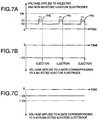
- the processor 202 when powered, controls the voltage controller 403 such that a positive voltage pulse Vej having a peak voltage V1 and a pulse width of T1 is applied to both selected and non-selected ejection electrodes and a positive voltage V2 ( ⁇ V1) is applied to them during intervals between the positive voltage pulses Vej (see Fig. 7A).
- the processor 202 controls the gate electrode voltage controller 402 such that a negative gate voltage -V3 is applied to the gate electrode corresponding to the selected ejection electrode (see Fig. 7B) and a negative voltage -V5 (> -V3) is applied to the gate electrode corresponding to the non-selected ejection electrode (see Fig. 7C).
- the negative voltage -V4 which is equal to or lower than -V3 is applied to the counter electrode 108.
- V1, V2, -V3, -V4, and -V5 so as to satisfy the following relationship: -V4 ⁇ -V3 ⁇ -V5 ⁇ 0 ⁇ V2 ⁇ V1 ⁇ V th , V1 + V3 ⁇ V th and V1 + V5 ⁇ V th , where V3 and V5 are the absolute values of -V3 and -V5, respectively.
- the ink ejection occurs only when a voltage difference between the ejection electrode and the corresponding gate electrode is equal to or greater than the threshold value V th . Therefore, in the case where V1 + V3 ⁇ V th , that is, the voltage difference between V1 and -V3 is not smaller than V th , the selected ejection electrode ejects ink particles on the falling edge of each ejection positive voltage pulse Vej as shown in Figs. 7A and 7B. When V1 + V5 ⁇ V th , no ink ejection occurs. Further, since the same positive voltage wave form is applied to both selected and non-selected ejection electrodes at all times as shown in Fig.
- the electric field between adjacent ejection electrodes falls into zero. Therefore, there does not occur the drift of particulate matter included in the ink between the selected and non-selected ejection electrodes, resulting in improved meniscuses 301 formed on the front ends of the ejection electrodes 101.
- the respective voltages are set such that the ink ejection occurs only when a voltage difference between the ejection electrode and the corresponding gate electrode is equal to or greater than the threshold value V th . Therefore, in the first and second embodiments, the positive voltages V1 and V2 and the negative voltages -V3, -V4 and -V5 should be relatively set so as to satisfy the above relationship. In other words, there is no need to set the gate electrode voltage and the counter electrode voltage to negative voltages as described above.
Landscapes
- Particle Formation And Scattering Control In Inkjet Printers (AREA)
Abstract
Description
Claims (19)
- An inkjet recording apparatus comprising:a plurality of ejection electrodes (101) arranged in an ink chamber containing ink (105) including particulate matter,
characterized by:a gate electrode plate (110, 401) having a plurality of gate electrodes therein, the gate electrodes corresponding to the ejection electrodes, respectively, and each gate electrode having an opening (111) therein, wherein each ejection electrode is directed to an opening of a gate electrode corresponding to the ejection electrode; anda controller (201, 202, 203, 402, 403) for generating a voltage difference between the ejection electrode and the gate electrode, the voltage difference changing between a first value and a second value depending on an input signal, wherein the first value is equal to or greater than a predetermined value and the second value is smaller than the predetermined value, the predetermined value being a minimum value which causes ejection of particulate matter from each ejection electrode. - The inkjet recording apparatus according to claim 1, wherein the gate electrodes are electrically connected to each other and the controller generates the voltage difference between the ejection electrode and the gate electrodes.
- The inkjet recording apparatus according to claim 2, wherein the controller comprises:a first voltage controller (201) for applying a control voltage to the ejection electrode, the control voltage varying depending on the input signal when the ejection electrode is selected for ejection; anda second voltage controller (203) for applying a predetermined voltage (-V3) to the gate electrodes, wherein the voltage difference is produced from the control voltage and the predetermined voltage.
- The inkjet recording apparatus according to claim 3, wherein the control voltage changes between a first voltage (V1) and a second voltage (V2) depending on the input signal when the ejection electrode is selected for ejection, the second voltage (V2) being applied to the ejection electrodes other than the ejection electrode which is selected for ejection,
wherein the first voltage is applied to the ejection electrode for a predetermined period (T1) to perform ejection of particulate matter and the second voltage is applied to the ejection electrode during periods other than the predetermined period. - The inkjet recording apparatus according to any of claims 2-4, further comprising:a counter electrode (108) to which the ejection electrode is directed such that the gate electrode plate is located between the ejection electrodes and the counter electrode, wherein a second voltage difference between the ejection electrodes and the counter electrode is equal to or greater than the voltage difference.
- The inkjet recording apparatus according to claim 5, wherein the controller comprises:a first voltage controller (201) for applying a control voltage to the ejection electrode, the control voltage varying depending on the input signal when the ejection electrode is selected for ejection;a second voltage controller (203) for applying a first predetermined voltage to the gate electrodes, wherein the voltage difference is produced from the control voltage and the predetermined voltage; anda third voltage controller (204) for applying a second predetermined voltage to the counter electrode to produce the second voltage difference.
- The inkjet recording apparatus according to claim 1, wherein the gate electrodes (G1-GN) are electrically isolated from each other and the controller (201, 402, 403) generates the voltage difference between the ejection electrode and the gate electrode.
- The inkjet recording apparatus according to claim 7, wherein the controller comprises:a first voltage controller (403) for applying a first control voltage to the ejection electrodes (101), the first control voltage varying in a predetermined timing; anda second voltage controller (402) for applying a second control voltage to the gate electrode, the second control voltage changing depending on the input signal, wherein the voltage difference is produced from the first and second control voltages.
- The inkjet recording apparatus according to claim 8, whereinthe first control voltage changes between a first voltage (V1) and a second voltage (V2) such that the first voltage is applied to the ejection electrodes for a predetermined period (T1) and the second voltage is applied to the ejection electrodes during periods other than the predetermined period, andthe second control voltage changes between a third voltage (-V3) and a fourth voltage (-V5) depending on the input signal such that the third voltage is applied to the gate electrode corresponding to the ejection electrode when the ejection electrode is selected for ejection and otherwise the fourth voltage is applied to the gate electrode.
- The inkjet recording apparatus according to any of claims 7-9, further comprising:a counter-electrode (108) to which the ejection electrode is directed such that the gate electrode plate is located between the ejection electrodes and the counter electrode, wherein a second voltage difference between the ejection electrodes and the counter electrode is equal to or greater than the voltage difference.
- The inkjet recording apparatus according to claim 10, wherein the controller comprises:a first voltage controller (403) for applying a first control voltage to the ejection electrodes, the first control voltage varying depending on the input signal when at least one ejection electrode is selected for ejection;a second voltage controller (402) for applying a second control voltage to the gate electrode, the second control voltage changing depending on the input signal, wherein the voltage difference is produced from the first and second control voltages;
anda third voltage controller (204) for applying a predetermined voltage to the counter electrode to produce the second voltage difference. - An inkjet recording apparatus comprising:an ink chamber having an slit (106) at a front end thereof and having an electrophoresis electrode (107) at a rear end thereof, the ink chamber containing ink including particulate matter; anda plurality of ejection electrodes (101) arranged in line within the slit of the ink chamber,
characterized by:a gate electrode plate (110, 401) having a plurality of gate electrodes therein and standing at a predetermined position away from the ejection electrodes such that the gate electrodes correspond to the ejection electrodes, respectively, and each gate electrode having an opening therein, wherein each ejection electrode is directed to an opening of a gate electrode corresponding to the ejection electrode;a counter electrode (108) to which the ejection electrode is directed such that the gate electrode plate is located between the ejection electrodes and the counter electrode; anda controller (201-204, 402, 403) for generating a first voltage difference between the ejection electrode and the gate electrode and a second voltage difference between the ejection electrode and the counter electrode, the first voltage difference changing between a first value and a second value depending on an input signal and the second voltage difference being equal to or greater than the first voltage difference, wherein the first value is equal to or greater than a predetermined value and the second value is smaller than the predetermined value, the predetermined value being a minimum value which causes ejection of particulate matter from each ejection electrode. - The inkjet recording apparatus according to claim 12, wherein the controller further generates a third voltage difference between the electrophoresis electrode and the gate electrode plate, the third voltage difference being the same direction as the first and second voltage differences.
- The inkjet recording apparatus according to claim 12 or 13, wherein the gate electrodes are electrically connected to each other and the controller generates the first voltage difference between the ejection electrode and the gate electrodes.
- The inkjet recording apparatus according to claim 14, wherein the controller comprises:a first voltage controller (201) for applying a control voltage to the ejection electrode, the control voltage varying between a first voltage and a second voltage depending on the input signal when the ejection electrode is selected for ejection, the second voltage being applied to the ejection electrodes other than the ejection electrode which is selected for ejection, wherein the control voltage comprises a plurality of voltage pulses each having the first voltage and a predetermined pulse width depending on the input signal when the ejection electrode is selected for ejection, wherein the voltage pulses are applied to the ejection electrode to perform ejection of particulate matter and the second voltage is applied to the ejection electrode during intervals between the voltage pulses; anda second voltage controller (203) for applying a predetermined voltage to the gate electrodes, wherein the voltage difference is produced from the control voltage and the predetermined voltage.
- The inkjet recording apparatus according to claim 12 or 13, wherein the gate electrodes are electrically isolated from each other and the controller generates the first voltage difference between the ejection electrode and the gate electrode.
- The inkjet recording apparatus according to claim 16, wherein the controller comprises:a first voltage controller (403) for applying a first control voltage to all the ejection electrodes, the first control voltage varying between a first voltage and a second voltage in a predetermined timing, wherein the first control voltage comprises a plurality of voltage pulses having the first voltage and a predetermined pulse width such that the voltage pulses are applied to the ejection electrodes and the second voltage is applied to the ejection electrodes during intervals between the voltage pulses; anda second voltage controller (402) for applying a second control voltage to the gate electrode, the second control voltage changing depending on the input signal, wherein the voltage difference is produced from the first and second control voltages, wherein the second control voltage changes between a third voltage and a fourth voltage depending on the input signal such that the third voltage is applied to the gate electrode corresponding to the ejection electrode when the ejection electrode is selected for ejection and otherwise the fourth voltage is applied to the gate electrode
- In an inkjet recording apparatus comprising:a plurality of ejection electrodes (101) arranged in an ink chamber containing ink including particulate matter; anda gate electrode plate (110) having a plurality of gate electrodes therein, the gate electrodes corresponding to the ejection electrodes, respectively, and each gate electrode having an opening therein, wherein each ejection electrode is directed to an opening of a gate electrode corresponding to the ejection electrode,a control method characterized by the steps of:applying a first voltage to the ejection electrode, the first voltage varying between a first level (V1) and a second level (V2) depending on the input signal when the ejection electrode is selected for ejection, the first voltage being kept at the second level when the ejection electrode is not selected for ejection; andapplying a second voltage different from the first voltage to the gate electrodes to producing a voltage difference between the ejection electrode and the gate electrode, the voltage difference changing between a first value and a second value depending on the input signal, wherein the first value is equal to or greater than a predetermined value and the second value is smaller than the predetermined value, the predetermined value being a minimum value which causes ejection of particulate matter from each ejection electrode.
- In an inkjet recording apparatus comprising:a plurality of ejection electrodes (101) arranged in an ink chamber containing ink including particulate matter; anda gate electrode plate (401) having a plurality of gate electrodes therein, the gate electrodes corresponding to the ejection electrodes, respectively, and each gate electrode having an opening therein, wherein each ejection electrode is directed to an opening of a gate electrode corresponding to the ejection electrode,a control method characterized by the steps of:applying a first voltage to all the ejection electrodes, the first voltage varying between a first level (V1) and a second level (V2) in a predetermined timing; andapplying a second voltage to the gate electrode corresponding to the ejection electrode which is selected for ejection to produce a voltage difference between the ejection electrode and the gate electrode, the second voltage changing between two different voltages depending on the input signal, the voltage difference changing between a first value and a second value depending on the input signal, wherein the first value is equal to or greater than a predetermined value and the second value is smaller than the predetermined value, the predetermined value being a minimum value which causes ejection of particulate matter from each ejection electrode.
Applications Claiming Priority (3)
| Application Number | Priority Date | Filing Date | Title |
|---|---|---|---|
| JP279209/96 | 1996-10-22 | ||
| JP8279209A JP2826537B2 (en) | 1996-10-22 | 1996-10-22 | Ink jet recording device |
| JP27920996 | 1996-10-22 |
Publications (3)
| Publication Number | Publication Date |
|---|---|
| EP0838335A2 true EP0838335A2 (en) | 1998-04-29 |
| EP0838335A3 EP0838335A3 (en) | 1999-02-03 |
| EP0838335B1 EP0838335B1 (en) | 2003-01-22 |
Family
ID=17607962
Family Applications (1)
| Application Number | Title | Priority Date | Filing Date |
|---|---|---|---|
| EP97118364A Expired - Lifetime EP0838335B1 (en) | 1996-10-22 | 1997-10-22 | Ink-jet recording appartus |
Country Status (5)
| Country | Link |
|---|---|
| US (1) | US6224193B1 (en) |
| EP (1) | EP0838335B1 (en) |
| JP (1) | JP2826537B2 (en) |
| AU (1) | AU718826B2 (en) |
| DE (1) | DE69718599T2 (en) |
Cited By (4)
| Publication number | Priority date | Publication date | Assignee | Title |
|---|---|---|---|---|
| EP0962319A2 (en) * | 1998-06-05 | 1999-12-08 | Seiko Instruments Information Devices Inc. | Ink jet method |
| EP1225048A1 (en) * | 2001-01-18 | 2002-07-24 | Tonejet Corporation Pty Ltd | Electrode for a drop-on-demand printer |
| EP1366901A1 (en) * | 2002-05-31 | 2003-12-03 | Tonejet Limited | Printhead |
| EP1461796A1 (en) * | 2001-10-31 | 2004-09-29 | Sri International | System and method of micro-fluidic handling and dispensing using micro-nozzle structures |
Families Citing this family (4)
| Publication number | Priority date | Publication date | Assignee | Title |
|---|---|---|---|---|
| JP2001191535A (en) * | 1999-10-29 | 2001-07-17 | Seiko Instruments Inc | Ink jet recording head and image recorder |
| US6879162B2 (en) * | 2000-11-07 | 2005-04-12 | Sri International | System and method of micro-fluidic handling and dispensing using micro-nozzle structures |
| US7559627B2 (en) * | 2004-03-12 | 2009-07-14 | Infoprint Solutions Company, Llc | Apparatus, system, and method for electrorheological printing |
| CN102066113B (en) * | 2008-07-09 | 2014-05-14 | 株式会社Enjet | Apparatus for jetting droplet and apparatus for jetting droplet using nanotip |
Citations (5)
| Publication number | Priority date | Publication date | Assignee | Title |
|---|---|---|---|---|
| US4477869A (en) * | 1983-04-28 | 1984-10-16 | Burroughs Corporation | Pulsed aperture for an electrostatic ink jet system |
| US4504844A (en) * | 1981-10-20 | 1985-03-12 | Ricoh Company, Ltd. | Ink jet printing apparatus |
| US4684957A (en) * | 1985-07-16 | 1987-08-04 | Matsushita Electric Industrial Co., Ltd. | Method for operation of an ink jet printing head |
| WO1993011866A1 (en) * | 1991-12-18 | 1993-06-24 | Research Laboratories Of Australia Pty. Ltd. | Method and apparatus for the production of discrete agglomerations of particulate matter |
| EP0813965A2 (en) * | 1996-06-17 | 1997-12-29 | NEC Corporation | Electrostatic ink jet printer having gate electrode and printing head thereof |
Family Cites Families (4)
| Publication number | Priority date | Publication date | Assignee | Title |
|---|---|---|---|---|
| JPS60228162A (en) | 1984-04-26 | 1985-11-13 | Tokyo Electric Co Ltd | Ink jet printer head |
| JP3315268B2 (en) * | 1994-09-22 | 2002-08-19 | 株式会社東芝 | Image forming device |
| JPH10509393A (en) * | 1995-05-04 | 1998-09-14 | デルファクス システムズ | Charge image forming method and charge deposition print head |
| JP2783225B2 (en) * | 1995-12-05 | 1998-08-06 | 日本電気株式会社 | Ink jet head device |
-
1996
- 1996-10-22 JP JP8279209A patent/JP2826537B2/en not_active Expired - Fee Related
-
1997
- 1997-10-22 US US08/956,065 patent/US6224193B1/en not_active Expired - Fee Related
- 1997-10-22 DE DE69718599T patent/DE69718599T2/en not_active Expired - Fee Related
- 1997-10-22 AU AU42770/97A patent/AU718826B2/en not_active Ceased
- 1997-10-22 EP EP97118364A patent/EP0838335B1/en not_active Expired - Lifetime
Patent Citations (5)
| Publication number | Priority date | Publication date | Assignee | Title |
|---|---|---|---|---|
| US4504844A (en) * | 1981-10-20 | 1985-03-12 | Ricoh Company, Ltd. | Ink jet printing apparatus |
| US4477869A (en) * | 1983-04-28 | 1984-10-16 | Burroughs Corporation | Pulsed aperture for an electrostatic ink jet system |
| US4684957A (en) * | 1985-07-16 | 1987-08-04 | Matsushita Electric Industrial Co., Ltd. | Method for operation of an ink jet printing head |
| WO1993011866A1 (en) * | 1991-12-18 | 1993-06-24 | Research Laboratories Of Australia Pty. Ltd. | Method and apparatus for the production of discrete agglomerations of particulate matter |
| EP0813965A2 (en) * | 1996-06-17 | 1997-12-29 | NEC Corporation | Electrostatic ink jet printer having gate electrode and printing head thereof |
Cited By (13)
| Publication number | Priority date | Publication date | Assignee | Title |
|---|---|---|---|---|
| EP0962319A2 (en) * | 1998-06-05 | 1999-12-08 | Seiko Instruments Information Devices Inc. | Ink jet method |
| EP0962319A3 (en) * | 1998-06-05 | 2000-07-12 | Seiko Instruments Information Devices Inc. | Ink jet method |
| US6331047B1 (en) | 1998-06-05 | 2001-12-18 | Seiko Instruments Inc. | Ink recording head and ink injecting method using ink recording head |
| US6926387B2 (en) | 2001-01-18 | 2005-08-09 | Tonejet Limited | Electrodes for a drop-on demand printer |
| WO2002057085A1 (en) * | 2001-01-18 | 2002-07-25 | Tonejet Limited | Electrodes for a drop-on-demand printer |
| AU2002220890B2 (en) * | 2001-01-18 | 2005-06-23 | Tonejet Limited | Electrodes for a drop-on-demand printer |
| EP1225048A1 (en) * | 2001-01-18 | 2002-07-24 | Tonejet Corporation Pty Ltd | Electrode for a drop-on-demand printer |
| EP1461796A1 (en) * | 2001-10-31 | 2004-09-29 | Sri International | System and method of micro-fluidic handling and dispensing using micro-nozzle structures |
| EP1461796A4 (en) * | 2001-10-31 | 2006-11-15 | Stanford Res Inst Int | System and method of micro-fluidic handling and dispensing using micro-nozzle structures |
| EP1366901A1 (en) * | 2002-05-31 | 2003-12-03 | Tonejet Limited | Printhead |
| WO2003101741A3 (en) * | 2002-05-31 | 2004-03-18 | Tonejet Ltd | Printhead |
| CN1317126C (en) * | 2002-05-31 | 2007-05-23 | 唐杰有限公司 | Printhead |
| US7387366B2 (en) | 2002-05-31 | 2008-06-17 | Tonejet Limited | Printhead |
Also Published As
| Publication number | Publication date |
|---|---|
| EP0838335B1 (en) | 2003-01-22 |
| EP0838335A3 (en) | 1999-02-03 |
| US6224193B1 (en) | 2001-05-01 |
| DE69718599T2 (en) | 2003-12-04 |
| DE69718599D1 (en) | 2003-02-27 |
| AU718826B2 (en) | 2000-04-20 |
| AU4277097A (en) | 1998-04-30 |
| JPH10119287A (en) | 1998-05-12 |
| JP2826537B2 (en) | 1998-11-18 |
Similar Documents
| Publication | Publication Date | Title |
|---|---|---|
| EP0838335B1 (en) | Ink-jet recording appartus | |
| EP0811496B1 (en) | Control of inkjet ejection electrodes | |
| US6190004B1 (en) | Inkjet recording apparatus | |
| US6130691A (en) | Inkjet recording apparatus having specific driving circuitry for driving electrophoresis electrodes | |
| EP0822076B1 (en) | Inkjet recording apparatus and control of the same | |
| JP2783206B2 (en) | Inkjet printer device | |
| US5997133A (en) | Inkjet recording apparatus having a minimum number of ejection electrode driving circuits and method for driving same | |
| US6120122A (en) | Inkjet recording apparatus | |
| JPH0717062B2 (en) | Image recording method | |
| JP2000334960A (en) | Electrostatic type ink jet recording apparatus | |
| JP2830864B2 (en) | Electrostatic inkjet recording device | |
| JP2826531B2 (en) | Electrostatic inkjet recording device | |
| JP2885741B2 (en) | Electrostatic inkjet recording device | |
| JP2826517B2 (en) | Ink jet recording device | |
| JP2885715B2 (en) | Head drive control method of electrostatic ink jet recording device | |
| JP2735030B2 (en) | Inkjet printer device | |
| JP2859192B2 (en) | Ink jet recording device | |
| JPH0957974A (en) | Ink jet printer | |
| JPS61127357A (en) | Ink jet recorder | |
| JPS62225388A (en) | Image recording method and image recording apparatus | |
| JP2003231258A (en) | Electrostatic ink jet recorder | |
| JP2001030497A (en) | Printer | |
| JPH11263017A (en) | Ink jet recording apparatus | |
| JPH10296981A (en) | Recorder | |
| JP2000263791A (en) | Ink jet recording apparatus |
Legal Events
| Date | Code | Title | Description |
|---|---|---|---|
| PUAI | Public reference made under article 153(3) epc to a published international application that has entered the european phase |
Free format text: ORIGINAL CODE: 0009012 |
|
| AK | Designated contracting states |
Kind code of ref document: A2 Designated state(s): DE FR GB |
|
| AX | Request for extension of the european patent |
Free format text: AL;LT;LV;RO;SI |
|
| PUAL | Search report despatched |
Free format text: ORIGINAL CODE: 0009013 |
|
| AK | Designated contracting states |
Kind code of ref document: A3 Designated state(s): AT BE CH DE DK ES FI FR GB GR IE IT LI LU MC NL PT SE |
|
| AX | Request for extension of the european patent |
Free format text: AL;LT;LV;RO;SI |
|
| 17P | Request for examination filed |
Effective date: 19990319 |
|
| AKX | Designation fees paid |
Free format text: DE FR GB |
|
| 17Q | First examination report despatched |
Effective date: 20001027 |
|
| GRAG | Despatch of communication of intention to grant |
Free format text: ORIGINAL CODE: EPIDOS AGRA |
|
| GRAG | Despatch of communication of intention to grant |
Free format text: ORIGINAL CODE: EPIDOS AGRA |
|
| GRAG | Despatch of communication of intention to grant |
Free format text: ORIGINAL CODE: EPIDOS AGRA |
|
| GRAH | Despatch of communication of intention to grant a patent |
Free format text: ORIGINAL CODE: EPIDOS IGRA |
|
| GRAH | Despatch of communication of intention to grant a patent |
Free format text: ORIGINAL CODE: EPIDOS IGRA |
|
| GRAA | (expected) grant |
Free format text: ORIGINAL CODE: 0009210 |
|
| AK | Designated contracting states |
Kind code of ref document: B1 Designated state(s): DE FR GB |
|
| REG | Reference to a national code |
Ref country code: GB Ref legal event code: FG4D |
|
| REF | Corresponds to: |
Ref document number: 69718599 Country of ref document: DE Date of ref document: 20030227 Kind code of ref document: P |
|
| ET | Fr: translation filed | ||
| PLBE | No opposition filed within time limit |
Free format text: ORIGINAL CODE: 0009261 |
|
| STAA | Information on the status of an ep patent application or granted ep patent |
Free format text: STATUS: NO OPPOSITION FILED WITHIN TIME LIMIT |
|
| 26N | No opposition filed |
Effective date: 20031023 |
|
| PGFP | Annual fee paid to national office [announced via postgrant information from national office to epo] |
Ref country code: GB Payment date: 20061018 Year of fee payment: 10 |
|
| PGFP | Annual fee paid to national office [announced via postgrant information from national office to epo] |
Ref country code: DE Payment date: 20061019 Year of fee payment: 10 |
|
| GBPC | Gb: european patent ceased through non-payment of renewal fee |
Effective date: 20071022 |
|
| PG25 | Lapsed in a contracting state [announced via postgrant information from national office to epo] |
Ref country code: DE Free format text: LAPSE BECAUSE OF NON-PAYMENT OF DUE FEES Effective date: 20080501 |
|
| REG | Reference to a national code |
Ref country code: FR Ref legal event code: ST Effective date: 20080630 |
|
| PGFP | Annual fee paid to national office [announced via postgrant information from national office to epo] |
Ref country code: FR Payment date: 20061010 Year of fee payment: 10 |
|
| PG25 | Lapsed in a contracting state [announced via postgrant information from national office to epo] |
Ref country code: GB Free format text: LAPSE BECAUSE OF NON-PAYMENT OF DUE FEES Effective date: 20071022 |
|
| PG25 | Lapsed in a contracting state [announced via postgrant information from national office to epo] |
Ref country code: FR Free format text: LAPSE BECAUSE OF NON-PAYMENT OF DUE FEES Effective date: 20071031 |