EP0838201B1 - Control appliance for the connection of dental, dental technical or precise mechanical treating instruments or handpieces - Google Patents
Control appliance for the connection of dental, dental technical or precise mechanical treating instruments or handpieces Download PDFInfo
- Publication number
- EP0838201B1 EP0838201B1 EP97118543A EP97118543A EP0838201B1 EP 0838201 B1 EP0838201 B1 EP 0838201B1 EP 97118543 A EP97118543 A EP 97118543A EP 97118543 A EP97118543 A EP 97118543A EP 0838201 B1 EP0838201 B1 EP 0838201B1
- Authority
- EP
- European Patent Office
- Prior art keywords
- control apparatus
- handpieces
- connection
- drive systems
- instruments
- Prior art date
- Legal status (The legal status is an assumption and is not a legal conclusion. Google has not performed a legal analysis and makes no representation as to the accuracy of the status listed.)
- Expired - Lifetime
Links
Images


Classifications
-
- A—HUMAN NECESSITIES
- A61—MEDICAL OR VETERINARY SCIENCE; HYGIENE
- A61C—DENTISTRY; APPARATUS OR METHODS FOR ORAL OR DENTAL HYGIENE
- A61C1/00—Dental machines for boring or cutting ; General features of dental machines or apparatus, e.g. hand-piece design
- A61C1/0007—Control devices or systems
-
- A—HUMAN NECESSITIES
- A61—MEDICAL OR VETERINARY SCIENCE; HYGIENE
- A61C—DENTISTRY; APPARATUS OR METHODS FOR ORAL OR DENTAL HYGIENE
- A61C1/00—Dental machines for boring or cutting ; General features of dental machines or apparatus, e.g. hand-piece design
- A61C1/0007—Control devices or systems
- A61C1/0015—Electrical systems
- A61C1/0023—Foot control
Definitions
- the invention relates to a control device for connecting one or more dental, dental technology or precision engineering treatment instruments or Handpieces according to the preamble of claim 1.
- German utility model DE 92 18 191 U1 a device for control and Power supply of several consumers of a dental treatment center with one central energy supply unit and with a control unit that reveals all Consumers common power module, which is dependent on Control signals from the control unit provide the right supply media for every consumer provides.
- control systems are capable of several different machining tools or treatment tools according to their Characteristics and their use with the required equipment (electrical current, Compressed air, water, etc.).
- required equipment electrical current, Compressed air, water, etc.
- control system only devices can be connected and controlled, their drive systems are based on the same physical principle.
- EP-A1-0 110 200 describes a control device of the type specified at the outset.
- This known control device has several connection devices for several Treatment instruments on, the device-side connection fittings on one of easily accessible outside of the control unit are arranged.
- the group of device-side connection fittings and the group of instrument-side Connection fittings are structurally identical and with the help of light Detachable connecting means can be connected to each other, so that the in the Connection fittings arranged coupling and counter links for the individual Resources are arranged in a spatial position to each other, which according to a Resources of all of these instruments are defined in such a way that the instrument-side connection fittings in the device-side connection fittings in Any combination can be connected, and that the connection fittings contain mechanically interacting coding means which when connected Instrument-side connection fitting to one of the device-side connection fittings Give signals to evaluation electronics, which then control organs for the Switch on the equipment assigned to the treatment instrument concerned.
- the drive systems of all instruments used with the same setting and / or actuating elements e.g. knee switch, Foot rocker arm, potentiometer, foot switch
- switchable and controllable e.g.
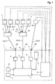
- Fig. 1 shows a block diagram for explaining the operation of a first Embodiment.
- the components of the control device 1 according to the invention are shown within the dashed rectangle.
- the control device 1 shown contains three different supply units 2 for Different drive systems, for example for three-phase motors, for brushless ones DC motors and for collector motors.
- the power outputs of the three Supply units 2 rest on appropriately trained connection devices 3.
- connection devices 3 treatment instruments or Handpieces 4 with different drive systems are connected, being on it It is important to ensure that the instruments or handpieces 4 correspond to those of theirs Drive systems require supply to the appropriate connection device 3 be connected.
- the connection devices 3 are depending on Supply unit 2 or depending on the drive system to be controlled characteristic and distinguishable so that incorrect connection by the user can be excluded.
- connection devices 3 are used for the use of several Instruments or handpieces 4 of the same type of drive.
- a number of connection devices 3 to be expanded by the same Supply unit 2 can be controlled.
- connection devices 3 for one Supply unit 2 must be analogous to the above distribution device 5 between parallel Connection devices 3 and supply unit 2 also a distribution device are switched or arranged, each only the one, the instrument used or handpiece 4 controls or connects the corresponding connecting device 3.
- control device 1 is advantageously used for the purpose of simpler extension of connecting devices 3 constructed modularly.
- control unit 1 contains a Detection device 6. This detection device 6 recognizes which instrument or Handpiece 4 was removed from its storage, and indicates a corresponding signal a central control unit 7 in control unit 1.
- the detection device 6 consists of switching elements directly on Control unit 1 or external switching elements on the instruments or handpieces 4 or the trays via which the user manually removes the treatment instrument or handpiece 4. Some are also from the general state of the art further devices for automatic detection of the removal of a Treatment instrument or handpiece 4 known from a storage device.
- Handpiece 4 can be encoded with a characteristic resistance value. To Removal of a handpiece 4 from the corresponding storage device connected resistance value measured and based on the measured Resistance value based on the connected instrument type.
- Another variant for recording the removal of an instrument or handpiece 4 is based on an opto-electronic principle.
- the removal or storage of the instruments or handpieces 4 is detected, for example, via light barriers connected to the Trays are provided.
- the detection device 6 recognizes the storage position of the removed instrument or handpiece 4 and thus also the connecting device 3, via which the relevant Instrument 4 can be controlled. This data is from the capture device 6 transmitted to the central control unit 7.
- the control unit 7 determines on the basis of that from the detection device 6 transmitted data the type of the removed instrument or handpiece 4, i.e. especially the drive system and the necessary equipment. This can be done using, for example suitable software and a control table integrated in the control unit 7. According to this result, the corresponding supply unit 2 and corresponding connection device 3 controlled with the required parameters. In the event of of several instruments 4 connected to a connecting device 3 must be from the control unit 7 also control data for the correct choice of the output of the Distribution device 5 are transmitted. Likewise, in the case of several at one Supply unit 2 of connected connecting devices 3 by the control unit 7 the right choice of connector 3 can be controlled.
- the set operating parameters and other information, such as Device type, connection device, drive type, speed, water supply, Air supply, error messages, times and the like, of the removed instrument or handpiece 4 can optionally be via one or more internal and / or external Display devices 8 are displayed to the user.
- the display devices 8 are preferably located directly on control unit 1 and / or in the user's field of vision.
- the user has the option of using one of them via an input device 9
- Enter the desired speed for the removed instrument or handpiece 4 is set by the control unit 7 via the corresponding supply unit 2.
- at least one display field for the rotational speed should be in the display device 8 be provided.
- the automatic specification of an average is also particularly advantageous Speed by the control unit 7 after detection of the type of instrument removed, the corresponds to an average speed for a typical application of the instrument type. Starting from this average speed setting by the control unit 7, the If necessary, the user can quickly change the speed to the desired value correct.
- control unit 7 of the control device 1 with a switch 10 for Commissioning of the respective instrument or handpiece 4 connected.
- the Control data are indeed from the time of removal of the supply units 2 and the instruments or handpieces 4 transmitted, for safety reasons the instruments or handpieces 4 are only put into operation when this is done by User is desired.
- commissioning of the instruments or Handpieces 4 locked by the control unit 7 as long as the instruments or Handpieces 4 are in their storage.
- switches 10 for example, foot switches, foot rocker arms, knee switch plates, Potentiometers or other known types of switches can be used. It is also conceivable the functions of speed selection and start-up of handpiece 4 together via to be able to enter a combined switch.
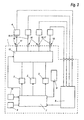
- FIG. 2 now shows a first exemplary embodiment of a control device 1 according to the invention shown.
- the control device 1 shown corresponds to the block diagram described above of Fig. 1.
- the control unit 1 has three electrical connection devices 3 for connecting three various electrical drive systems. Instead of or in addition to electrical connection devices 3 can of course also pneumatic Connection devices may be attached to control unit 1. As a detection device for Selection of the desired instrument or handpiece 4 are via the Connection devices 3 switches 6 attached to display the selected Instruments 4 can also be stored with light-emitting diodes.
- control device has a display device 8 in the form of an LCD display, a rotary knob as a speed input device 9 and a switch 10 for Commissioning of the instrument or handpiece 4.
- display device 8 in the form of an LCD display
- rotary knob as a speed input device 9
- switch 10 for Commissioning of the instrument or handpiece 4.
- an external connection device Display device connectable not shown.
- FIG. 3 shows a control device 1 with a central control unit 7, the three supply units 2 for different Drive systems controls, a detection device 6 to recognize which Instrument or handpiece 4 was removed from its storage, at least one Display device 8, a speed input device 9 and a switch 10 for Commissioning of the respective instrument or handpiece 4.
- this control device has several, e.g. four, universal connection devices 11 to which via universal connecting elements Instruments or handpieces 4 any electrical Drive systems can be connected. Analogous to the first embodiment above also here via (not shown) distribution devices 5 several instruments or Handpieces 4 can be connected to a connecting device 11, or the control unit 1 can be expanded by a number of universal connection devices 11.
- connection devices 11 over the specific ones Connection devices 3 for the user is obvious. For one thing, anyone can any instrument or handpiece 4 connected to each connector 11 and, on the other hand, the number of existing connection devices 11 always be used optimally. In the case of specific connection devices 3 it can happen that an expansion of the control unit 1 or the use of Distribution devices 5 is necessary, although not all of the existing ones Connection devices 3 are occupied, for example, for a drive system none Instruments or handpieces are needed.
- control unit 12 To each of the universal connection devices 11 with each supply unit 2 for the Different drive systems must be connected between the supply units 2 and the connection devices 11 a control unit 12 are switched.
- the Control unit 12 enables all possible control connections between the three Supply units 2 and the four connection devices 11 and switches accordingly a control signal from the central control unit 7 in each case the required connection by.
- FIG. 4 A corresponding to the operation of the block diagram of Fig. 3 Exemplary embodiment of a control device 1 is shown in FIG. 4. From the outer structure ago this control unit 1 essentially corresponds to the first embodiment. In this embodiment, however, the three connection devices are universal Connection devices 11 for connecting instruments or handpieces 4 any drive systems.
- control unit 1 of this Embodiment combines the functions of the first two Embodiments, i.e. its mode of operation corresponds to a combination of the two 1 and 3.
- control unit 1 is a pneumatic Connection device 13 attached.
- connection device 13 are instruments or handpieces 4 with pneumatic drive systems, such as air turbines, connected.
- connection device 13 is, of course, of further pneumatic type Connection devices 13 expandable to several with the control unit 1 Connect and control compressed air operated instruments or handpieces 4 at the same time to be able to.
- connection device 13 one or more (not shown) distribution devices for Connection of several instruments or handpieces 4 to a connection device 13 conceivable.
- the distribution device corresponds to the electrical one explained above Distribution device 5 only that instead of electrical lines and switches, of course Compressed air lines and switches must be used.
- the instruments or handpieces 4 are one or more Supply lines 15 for media formed by the operating resources assigned in the Functional operation for driving and cooling the handpiece and / or for cooling and / or for rinsing and / or cleaning and / or illuminating the treatment site to be used.
- These are electrical lines that are used to supply serve electrical current or, in particular, flexible pipelines leading to the supply air or water or a water / air mixture (spray).
- connection devices can each in the sense of the non-universal connection devices 3 or 3a or the universal Connection devices 11 can be provided to also several treatment instruments or handpieces 4 can be connected without and with distribution devices.
- a Treatment instrument or handpiece 4 simple function as is the case with the air hand nozzle 4c can be the case, a special simple connection device can also be provided his.
- the motor handpiece 4a Drive motor 16 extending first electrical line 15a for drive current, one to a lighting device arranged at the front end of the motor handpiece 4a 19 extending second electrical line 15b and one or more air lines, the each separately or as line branches to an air cooling device 21 for the Drive motor 16, to a rotary bearing 22 supported by compressed air for one Machining tool 23 holding drive shaft 24 of the motor handpiece 4a and to one Air nozzle 25 arranged in the front end region of motor handpiece 4a.
- two air lines 15c, 15d are provided, from those designated by 15c to the cooling device 21 and to the pivot bearing 22 branches and the 15d extends to the air nozzle 25. It is possible and depending on the purpose of use, also advantageous, in addition one not shown Provide water pipe that extends to one in the front end area of the motor handpiece 4a extends arranged water nozzle, which can be combined with the air nozzle 25.
- a drive air line 15e is provided for the turbine handpiece 4b a turbine 26 arranged in the front end region of the turbine handpiece 4b extends a rotary drive of a machining tool 23, an electrical line 15f, which extends to one in the front end region of the turbine handpiece 4b Lighting device 19 extends, a blown air line 15g, and a water line 15h, each for an air, water or spray outlet also in the front Extend the end region of the turbine handpiece 4b.
- Air line 15i may be arranged.
- Each media line 15 has in the area of the connection device 3 or 3a or 11 formed, preferably designed as a plug-in coupling, a pair Connecting elements or coupling elements for connecting or coupling the associated media line 15, which when coupling or uncoupling with Coupling part 18 are automatically connected or released and each as Quick or preferably plug-in coupling designed sine.
- a closure element preferably an in Direction to the coupling part 18 automatically closing check valve provided, that opens automatically when coupling and closes automatically when disconnected.
- the rear connector 4.1 and the front instrument part 4.2 are by a Quick coupling, in particular in the form of a plug-in coupling or plug-in / rotary coupling 31 connectable to each other and shown in Fig. 6 in the connected position.
- the z. B. radial dividing line between the rear connector 4.1 and the front Instrument part 4.2 is designated 32.
- the Plug / rotary coupling 31 an axial cylindrical or step-cylindrical Coupling pin 33a, which can be rotated into a coupling hole with little movement play 33b can be inserted.
- the coupling pin 33a can 4.2 protrude to the rear or protrude from the rear connection part 34.1 as is is shown.
- the coupling hole 33b is in the other of the aforementioned parts available.
- To secure the plug-in / rotary coupling 31 in the assembled Coupling position is one between the coupling pin 33a and the coupling hole 33b effective locking device 34 provided manually by an appropriate Tractive force can be suppressed and is therefore easy to handle.
- the media lines, here 15b to 15d, pass through the plug-in / rotary coupling 31, being the hollow cylindrical one Gap 32a between the coupling pin 33a and the coupling hole 33b Z-shaped push through sealed.
- connection devices 3, 3a, 11 or 13 are the aforementioned connection devices in contrast to the device side Connection devices with the same position numbers, however, each supplemented by .1 clarified, namely with 3.1, 3a.1, 11.1 and 13.1.
- This configuration is among others advantageous because the treatment tool or handpieces 4 without the Supply lines 17 can be connected, the supply lines 17 can remain on the control unit 1. With this configuration, therefore need in Connection area of the supply lines 17 on the device 1 none according to the invention Connection devices 3, 3a, 11 or 13 to be arranged.
- connecting devices ensuring the passage of the media.
- connection devices according to the invention on the instrument side is required in the presence of a specific connection device 3.1, 3a.1, in principle according to the connection device 3 or 3a described above, the presence the specific media lines in the connected to the rear connector 4.1 Supply line 17 and in the presence of a universal connection device 11.1 the presence of all media lines in the associated supply line 17.
- the other treatment instruments or handpieces 4b, 4c are related to the Connection devices 3.1, 3a.1, 11.1, 13.1 designed accordingly.
- the detection elements of the detection device 6 can also be used the respective trained in the sense of the connection device 3 or 3a or 11 Coupling part 18, 18.1 cooperate so that the respective controls 7 and 12, respectively the associated handpiece 4 controls the respective operating parameters. This also applies to the associated medium, the line 15 activated and possibly blocked or not.
- control unit 1 In addition to the control of different drive systems described above different supply units 2, it is also possible to use a control unit 1 several drive systems with the same physical principle, but different Connect requirements to the supply. For example, a more robust one (Larger) drive for rough work, a smaller, more convenient drive with less Efficiency for filigree work and a drive for high speeds, for Example of working out fissures or ceramic work on such Control device 1 according to the invention can be connected and operated by it.
- Control unit 1 can be used freely for all systems.
Abstract
Description
Die Erfindung betrifft ein Steuergerät zum Anschluß von einem oder mehreren
zahnärztlichen, zahntechnischen oder feinwerktechnischen Behandlungsinstrumenten oder
Handstücken nach dem Oberbegriff des Patentanspruches 1.The invention relates to a control device for connecting one or more
dental, dental technology or precision engineering treatment instruments or
Handpieces according to the preamble of
Insbesondere in der Zahntechnik werden heute zur Bearbeitung von Werkstücken mit rotierenden Werkzeugen Motorhandstücke eingesetzt, deren Antriebssysteme auf verschiedenen physikalischen Prinzipien beruhen. Verwendet werden hauptsächlich Kollektormotoren, Drehstromasynchronmotoren und zunehmend auch bürstenlose, elektrisch kommutierte Gleichstrommotoren. Parallel dazu kommen auch rein mit Druckluft betriebene Antriebe (Luftturbinen) zum Einsatz.In dental technology in particular, machining of workpieces is nowadays included rotating tools used motor handpieces, their drive systems on different physical principles. Are mainly used Collector motors, three-phase asynchronous motors and increasingly also brushless, electrically commutated DC motors. At the same time, come along too Compressed air operated drives (air turbines) are used.
Die Gründe für die Verwendung verschiedener Antriebssysteme sind vielfältig. Zum einen spielen wirtschaftliche Faktoren eine große Rolle, so sind beispielsweise Kollektormotorsysteme wegen des geringeren Steuerungsaufwandes erheblich preisgünstiger als andere Systeme.There are many reasons for using different drive systems. On the one hand economic factors play a major role, for example Collector motor systems considerably because of the lower control effort cheaper than other systems.
Zum anderen bestimmt die Anwendung das verwendete Motorsystem sehr stark mit. So erfordern z.B. Fräsarbeiten an Kunststoffen oder das Bearbeiten von Modellgußteilen leistungsstarke, robuste Antriebe, die auch genügend Leistungsreserven aufweisen müssen, um sich im Betrieb nicht übermäßig zu erwärmen. Dies sind Anwendungsbeispiele für Drehstrom- oder bürstenlose Gleichstrom-Antriebe. Solche Antriebssysteme sind auch bei Schleifarbeiten wegen der mit diesen Antrieben erzielbaren hohen Drehzahlen von Vorteil. Gleichstrommotoren mit Bürsten sind dagegen drehzahlmäßig durch den Kollektor begrenzt und würden bei hohen Leistungsanforderungen einem erhöhten Verschleiß unterliegen.On the other hand, the application very much determines the motor system used. So require e.g. Milling work on plastics or processing model castings powerful, robust drives, which must also have sufficient power reserves, so as not to heat up excessively during operation. These are application examples for Three-phase or brushless DC drives. Such drive systems are also at Grinding work is advantageous because of the high speeds that can be achieved with these drives. DC motors with brushes, however, are speed-wise due to the collector limited and would wear at high performance requirements subject.
Bei Edelmetall- oder Keramikarbeiten sind hingegen die preislich günstigeren und wegen des im allgemeinen geringeren Gewichtes und kleinerer Baugröße beweglicheren Kollektormotorantriebe von Vorteil. Zur Ausarbeitung von Fissuren wiederum sind Antriebe mit sehr hohen Drehzahlen erforderlich. Hier werden dann bevorzugt luftgetriebene Antriebe eingesetzt. For precious metal or ceramic work, however, are the cheaper and because the generally lower weight and smaller size more mobile Collector motor drives an advantage. To work out fissures are in turn Drives with very high speeds required. Here are then preferred air-driven drives used.
Diese unterschiedlichen, oben aufgeführten Faktoren führen dazu, daß in zahntechnischen Labors meist mehrere verschiedene Antriebssysteme zum Einsatz kommen.These different factors listed above cause that in dental technology Laboratories usually use several different drive systems.
Aufgrund des deutlichen Trends zu kleineren Laborgrößen werden zunehmend zentrale Steuereinheiten für verschiedene Motorhandstücke erforderlich. So ist beispielsweise in dem deutschen Gebrauchsmuster DE 92 18 191 U1 eine Einrichtung zur Steuerung und Stromversorgung mehrerer Verbraucher eines zahnärztlichen Behandlungsplatzes mit einer zentralen Energie-Versorgungseinheit und mit einer Steuereinheit offenbart, die einen allen Verbrauchern gemeinsamen Leistungsmodul aufweist, der in Abhängigkeit von Steuersignalen der Steuereinheit für jeden Verbraucher die passenden Versorgungsmedien zur Verfügung stellt.Due to the clear trend towards smaller laboratory sizes are becoming increasingly central Control units required for various motor handpieces. For example, in the German utility model DE 92 18 191 U1 a device for control and Power supply of several consumers of a dental treatment center with one central energy supply unit and with a control unit that reveals all Consumers common power module, which is dependent on Control signals from the control unit provide the right supply media for every consumer provides.
Weiter ist aus der DE 42 20 006 A1 ein Steuersystem für mehrere dentale Handstücke und zugehörige Einrichtungen bekannt, welches die Zufuhr von Luft und Wasser steuert, wobei die Fluide durch einen einzigen Verteiler zugeführt werden.Furthermore, from DE 42 20 006 A1 a control system for several dental handpieces and associated facilities known, which controls the supply of air and water, the fluids being fed through a single manifold.
Die vorgenannten sowie weitere bekannte Steuersysteme sind in der Lage, mehrere verschiedene Bearbeitungswerkzeuge oder Behandlungsinstrumente entsprechend ihrer Kenndaten und ihrer Verwendung mit den benötigten Betriebsmitteln (elektrischer Strom, Druckluft, Wasser, etc.) zu versorgen. Bei den bekannten Systemen können allerdings an ein Steuersystem nur Geräte angeschlossen und angesteuert werden, deren Antriebssysteme auf dem gleichen physikalischen Prinzip beruhen.The aforementioned and other known control systems are capable of several different machining tools or treatment tools according to their Characteristics and their use with the required equipment (electrical current, Compressed air, water, etc.). In the known systems, however, can a control system only devices can be connected and controlled, their drive systems are based on the same physical principle.
Sollen alle anfallenden Arbeiten von einem Techniker an einem Arbeitsplatz durchgeführt werden, so müssen nach dem heutigen Stand der Technik mehrere Steuer- und Antriebssysteme am Arbeitsplatz angebracht werden, um für alle Arbeiten den bestgeeigneten Antrieb einsetzen zu können. Da jedes Antriebssystem zudem sein eigenes Einstell- und/oder Betätigungselement hat (zumeist werden Kniesteuergeräte verwendet), ist dies sowohl aus Platz- als auch aus Handhabungsgründen nicht möglich. Should all work be carried out by a technician in one workplace are, according to the current state of the art, several control and Drive systems can be installed in the workplace in order for all work to use the most suitable drive. Because each drive system also has its own Has adjustment and / or actuating element (mostly knee control devices are used), this is not possible for reasons of space or handling.
In der EP-A1-0 110 200 ist ein Steuergerät der eingangs angegebenen Art beschrieben. Dieses vorbekannte Steuergerät weist mehrere Anschlußvorrichungen für mehrere Behandlungsinstrumente auf, wobei die geräteseitigen Anschlußarmaturen an einer von außen leicht zugänglichen Stelle des Steuergerätes angeordnet sind. Die Gruppe der geräteseitigen Anschlußarmaturen und die Gruppe der instrumentenseitigen Anschlußarmaturen sind jeweils baulich gleich ausgebildet und mit Hilfe von leicht lösbaren Verbindungsmitteln miteinander verbindbar, so daß die in den Anschlußarmaturen angeordneten Kupplungs- und Gegenglieder für die einzelnen Betriebsmittel in einer räumlichen Lage zueinander angeordnet sind, die nach einem die Betriebsmittel all dieser Instrumente berücksichtigenden Schema festgelegt sind, so daß die instrumentenseitigen Anschlußarmaturen in die geräteseitigen Anschlußarmaturen in beliebiger Kombination angeschlossen werden können, und daß die Anschlußarmaturen mechanisch zusammenwirkende Kodierungsmittel enthalten, die bei Anschluß einer instrumentenseitigen Anschlußarmatur an eine der geräteseitigen Anschlußarmaturen Signale an eine Auswerteelektronik geben, die dann Steuerorgane für die den betreffenden Behandlungsinstrument zugeordneten Betriebsmittel einschalten. EP-A1-0 110 200 describes a control device of the type specified at the outset. This known control device has several connection devices for several Treatment instruments on, the device-side connection fittings on one of easily accessible outside of the control unit are arranged. The group of device-side connection fittings and the group of instrument-side Connection fittings are structurally identical and with the help of light Detachable connecting means can be connected to each other, so that the in the Connection fittings arranged coupling and counter links for the individual Resources are arranged in a spatial position to each other, which according to a Resources of all of these instruments are defined in such a way that the instrument-side connection fittings in the device-side connection fittings in Any combination can be connected, and that the connection fittings contain mechanically interacting coding means which when connected Instrument-side connection fitting to one of the device-side connection fittings Give signals to evaluation electronics, which then control organs for the Switch on the equipment assigned to the treatment instrument concerned.
Es ist deshalb Aufgabe der Erfindung ein Steuergerät der eingangs genannten Art zu schaffen, das so ausgerüstet ist, daß es als Universalsteuergerät an einem Arbeitsplatz für mehrere Behandlungsinstrumente oder Handstücke, insbesondere auch unterschiedlicher Antriebssysteme, geeignet ist.It is therefore an object of the invention to provide a control device of the type mentioned create that is equipped so that it can be used as a universal control unit in a workplace for several treatment instruments or handpieces, especially different ones Drive systems is suitable.
Diese Aufgabe wird durch die Merkmale des Patentanspruches 1 gelöst. Weiterbildungen
und bevorzugte Ausgestaltungen der Erfindung sind Gegenstand der Unteransprüche. This object is solved by the features of
In Weiterbildung der Erfindung sind die Antriebssysteme aller eingesetzten Instrumente mit den gleichen Einstell- und/oder Betätigungselementen (z.B. Knieschaltplatte, Fußschwinghebel, Potentiometer, Fußschalter) schaltbar und steuerbar.In a further development of the invention, the drive systems of all instruments used with the same setting and / or actuating elements (e.g. knee switch, Foot rocker arm, potentiometer, foot switch) switchable and controllable.
Die Zuordnung, welches der angeschlossenen Instrumente oder Handstücke in Betrieb genommen werden soll, kann mittels verschiedener, allgemein bekannter Vorrichtungen bzw. Systeme erfolgen.The assignment of which of the connected instruments or handpieces is in operation can be taken using various, generally known devices or systems.
Im folgenden werden anhand der beigefügten Zeichnung verschiedene Ausführungsbeispiele eines erfindungsgemäßen Steuergerätes näher erläutert. Es zeigen:
- Fig. 1
- ein Blockschaltbild zur Erklärung der Funktionsweise eines ersten Ausführungsbeispieles;
- Fig. 2
- ein erstes Ausführungsbeispiel eines erfindungsgemäßen Steuergerätes in Prinzip-Darstellung;
- Fig. 3
- ein Blockschaltbild zur Erklärung der Funktionsweise eines zweiten Ausführungsbeispieles;
- Fig. 4
- ein zweites Ausführungsbeispiel eines erfindungsgemäßen Steuergerätes in Prinzip-Darstellung;
- Fig. 5
- ein drittes Ausführungsbeispiel eines erfindungsgemäßen Steuergerätes in Prinzip-Darstellung;
- Fig. 6
- das Steuergerät nach Fig. 5 in detaillierterer und abgewandelter Ausgestaltung.
- Fig. 1
- a block diagram for explaining the operation of a first embodiment;
- Fig. 2
- a first embodiment of a control device according to the invention in principle;
- Fig. 3
- a block diagram for explaining the operation of a second embodiment;
- Fig. 4
- a second embodiment of a control device according to the invention in principle;
- Fig. 5
- a third embodiment of a control device according to the invention in a schematic representation;
- Fig. 6
- 5 in a more detailed and modified configuration.
Fig. 1 zeigt ein Blockschaltbild zur Erklärung der Funktionsweise eines ersten
Ausführungsbeispieles. Die Komponenten des erfindungsgemäßen Steuergerätes 1 sind
innerhalb des gestrichelten Rechtecks dargestellt.Fig. 1 shows a block diagram for explaining the operation of a first
Embodiment. The components of the
Das dargestellte Steuergerät 1 enthält drei verschiedene Versorgungseinheiten 2 für
unterschiedliche Antriebssysteme, beispielsweise für Drehstrommotoren, für bürstenlose
Gleichstrommotoren und für Kollektormotoren. Die Leistungsausgänge der drei
Versorgungseinheiten 2 liegen an entsprechend ausgebildeten Anschlußvorrichtungen 3 an.The
An die verschiedenen Anschlußvorrichtungen 3 können Behandlungsinstrumente oder
Handstücke 4 mit unterschiedlichen Antriebssystemen angeschlossen werden, wobei darauf
zu achten ist, daß die Instrumente oder Handstücke 4 entsprechend der von ihren
Antriebssystemen benötigten Versorgung an die jeweils passende Anschlußvorrichtung 3
angeschlossen werden. Vorteilhafterweise sind die Anschlußvorrichtungen 3 je nach
Versorgungseinheit 2 bzw. je nach anzusteuerndem Antriebssystem charakteristisch und
unterscheidbar ausgebildet, so daß ein falsches Anschließen durch den Anwender
ausgeschlossen werden kann.At the
Es besteht auch die Möglichkeit, mehrere Instrumente oder Handstücke 4 der gleichen
Antriebsart zusammen an eine gemeinsame Anschlußvorrichtung 3 anzuschließen. In
diesem Fall muß zwischen die Anschlußvorrichtung 3 und der Instrumenten- oder
Handstücke-Gruppe 4 eine geeignete Verteilereinrichtung 5 als Adapter geschaltet bzw.
angeordnet werden. Dabei kann die Verteilereinrichtung 5 oder können mehrere
vorhandene Verteilereinrichtungen 5 an ihrer für den Anschluß der Instrumente oder
Handstücke 4 vorgesehenen Seite Anschlußvorrichtungen 3a aufweisen, die der
zugehörigen Anschlußvorrichtung 3 entsprechen und den wahlweisen Anschluß der
Instrumente oder Handstücke 4 gewährleisten.There is also the possibility of using several instruments or
An Stelle der Verwendung von Verteilereinrichtungen 5 Für den Einsatz von mehreren
Instrumenten oder Handstücken 4 gleicher Antriebsart kann ebenso das Steuergerät 1 um
eine Anzahl von Anschlußvorrichtungen 3 erweitert werden, die von der gleichen
Versorgungseinheit 2 angesteuert werden. Bei mehreren Anschlußvorrichtungen 3 für eine
Versorgungseinheit 2 muß analog zur obigen Verteilereinrichtung 5 zwischen parallelen
Anschlußvorrichtungen 3 und Versorgungseinheit 2 ebenfalls eine Verteilereinrichtung
geschaltet bzw. angeordnet werden, die jeweils nur die eine, dem benutzten Instrument
oder Handstück 4 entsprechende Anschlußvorrichtung 3 ansteuert bzw. verbindet.Instead of using
Prinzipiell ist die Versorgung einer beliebigen Anzahl von verschiedenen Antriebssystemen
mit einem Steuergerät 1 und eine beliebige Anzahl von Anschlußvorrichtungen 3 für jede
Versorgungseinheit 2 möglich. Vorteilhafterweise wird das Steuergerät 1 zum Zwecke der
einfacheren Erweiterung von Anschlußvorrichtungen 3 modulartig aufgebaut.In principle, the supply of any number of different drive systems
with a
Um eine Zuordnung zwischen einem aus seiner Ablage entnommenen Instrument oder
Handstück 4 und der entspechenden Versorgungseinheit 2 sowie (im Falle mehrerer
Anschlußvorrichtungen 3 einer Versorgungseinheit 2) der entsprechenden
Anschlußvorrichtungen 3 zu ermöglichen, enthält das Steuergerät 1 eine
Erfassungsvorrichtung 6. Diese Erfassungsvorrichtung 6 erkennt, welches Instrument oder
Handstück 4 aus seiner Ablage entnommen wurde, und gibt ein entsprechendes Signal an
eine zentrale Steuereinheit 7 im Steuergerät 1 weiter.To make an assignment between an instrument removed from its storage or
Die Erfassungsvorrichtung 6 besteht im einfachsten Fall aus Schaltelementen direkt am
Steuergerät 1 oder externen Schaltelementen an den Instrumenten oder Handstücken 4 oder
den Ablagen, über die der Anwender manuell das entnommene Behandlungsinstrument
oder Handstück 4 auswählt. Aus dem allgemeinen Stand der Technik sind zudem einige
weitere Vorrichtungen zur automatischen Erfassung der Entnahme eines
Behandlungsinstrumentes oder Handstückes 4 aus einer Ablagevorrichtung bekannt.In the simplest case, the
Als rein elektronische Erfassung kann beispielsweise jedes Behandlungsinstrument oder
Handstück 4 mit einem charakteristischen Widerstandswert kodiert werden. Nach
Entnahme eines Handstückes 4 aus der entsprechenden Ablagevorrichtung wird der
angeschlossene Widerstandswert gemessen und aufgrund des gemessenen
Widerstandswertes auf den angeschlossenen Instrumententyp geschlossen.Any treatment instrument or, for example, can be used as a purely
Eine mechanisch-elektronische Möglichkeit neben den bereits erwähnten Schaltelementen
ist dadurch gegeben, daß die Instrumente oder Handstücke 4 in speziell ausgebildeten
Ablagen angeordnet sind, die nur für die Aufnahme eines Typs ausgebildet sind. Bei
Entnahme eines Instrumentes oder Handstückes 4 wird die spezifische Ablageadresse
ermittelt und an die Steuereinheit übermittelt.A mechanical-electronic option in addition to the switching elements already mentioned
is given in that the instruments or
Eine weitere Variante zur Erfassung der Entnahme eines Instrumentes oder Handstückes 4
basiert auf einem opto-elektronischen Prinzip. Die Entnahme bzw. Ablage der Instrumente
oder Handstücke 4 wird dabei beispielsweise über Lichtschranken detektiert, die an den
Ablagen vorgesehen sind.Another variant for recording the removal of an instrument or
Als letztes sei noch die Nutzung von magnetischen Effekten genannt. Beispielsweise
werden in Spulen von charakteristischer Induktivität bei Entnahme oder Ablage eines
Handstückes 4 durch einen Ferritkern Induktionsströme induziert. Weiter kann auch die
Entnahme eines Instrumentes aus seiner Ablage aufgrund einer Änderung bzw. Störung
eines magnetischen Feldes überwacht werden. Die einzelnen Instrumente sind dabei mit
einem magnetischen Instrument versehen, so daß sich der magnetische Fluß in der Ablage
bei Vorhandensein der Instrumente in der Ablage von demjenigen bei der Entnahme des
Instrumentes aus der Ablage unterscheidet.Finally, the use of magnetic effects should be mentioned. For example
are in coils of characteristic inductance when removing or depositing a
Da bereits einige verschiedene Systeme mit unterschiedlichen Funktionsweisen zur
Erfassung der Entnahme eines Instrumentes oder Handstückes 4 aus dem Stand der
Technik bekannt sind und da ein solches Erkennungssystem an sich nicht Gegenstand der
vorliegenden Erfindung ist, sei zwecks genauerer Beschreibung und weiterer
Möglichkeiten an dieser Stelle nur auf die einschlägige Literatur zu diesem Thema
verwiesen. Since there are already several different systems with different functions
Detection of the removal of an instrument or
Die Erfassungsvorrichtung 6 erkennt die Ablageposition des entnommenen Instrumentes
oder Handstückes 4 und somit auch die Anschlußvorrichtung 3, über die das betreffende
Instrument 4 angesteuert werden kann. Diese Daten werden von der Erfassungsvorrichtung
6 an die zentrale Steuereinheit 7 übermittelt.The
Die Steuereinheit 7 ermittelt auf der Grundlage der von der Erfassungsvorrichtung 6
übermittelten Daten den Typ des entnommenen Instrumentes oder Handstückes 4, d.h.
insbesondere Antriebssystem und benötigte Betriebsmittel. Dies kann beispielsweise mittels
geeigneter Software und einer in der Steuereinheit 7 integrierten Steuertabelle geschehen.
Entsprechend diesem Ergebnis wird die entsprechende Versorgungseinheit 2 und die
entsprechende Anschlußvorrichtung 3 mit den benötigten Parametern angesteuert. Im Falle
von mehreren an einer Anschlußvorrichtung 3 angeschlossenen Instrumenten 4 müssen von
der Steuereinheit 7 zudem Steuerdaten für die richtige Wahl des Ausganges der
Verteilereinrichtung 5 übermittelt werden. Ebenso muß im Falle mehrerer an einer
Versorgungseinheit 2 angeschlossener Anschlußvorrichtungen 3 durch die Steuereinheit 7
die richtige Wahl der Anschlußvorrichtung 3 gesteuert werden.The
Die eingestellten Betriebsparameter und sonstige Informationen, wie zum Beispiel
Gerätetyp, Anschlußvorrichtung, Antriebsart, Drehzahl, Wasserversorgung,
Luftversorgung, Fehlermeldungen, Zeiten und dergleichen, des entnommenen Instruments
oder Handstückes 4 können wahlweise über eine oder mehrere interne und/oder externe
Anzeigevorrichtungen 8 dem Anwender angezeigt werden. Die Anzeigevorrichtungen 8
befinden sich vorzugsweise direkt am Steuergerät 1 und/oder im Blickfeld des Anwenders.The set operating parameters and other information, such as
Device type, connection device, drive type, speed, water supply,
Air supply, error messages, times and the like, of the removed instrument
or
Für den Anwender besteht die Möglichkeit, über eine Eingabeeinrichtung 9 eine von ihm
gewünschte Drehzahl für das entnommene Instrument oder Handstück 4 einzugeben, die
durch die Steuereinheit 7 über die entsprechende Versorgungseinheit 2 eingestellt wird.
Hierzu sollte in der Anzeigevorrichtung 8 zumindest ein Anzeigefeld für die Drehzahl
vorgesehen sein. Besonders vorteilhaft ist auch die automatische Vorgabe einer mittleren
Drehzahl durch die Steuereinheit 7 nach Erkennen des entnommenen Instrumententyps, die
einer mittleren Drehzahl für eine übliche Anwendung des Instrumententyps entspricht.
Ausgehend von dieser mittleren Drehzahlvorgabe durch die Steuereinheit 7 kann der
Anwender bei Bedarf die Drehzahl relativ schnell auf den von ihm gewünschten Wert
korrigieren.The user has the option of using one of them via an
Weiter ist die Steuereinheit 7 des Steuergerätes 1 mit einem Schalter 10 zur
Inbetriebnahme des jeweiligen Instruments oder Handstückes 4 verbunden. Die
Steuerdaten werden zwar ab dem Zeitpunkt der Entnahme den Versorgungseinheiten 2 und
den Instrumenten oder Handstücken 4 übermittelt, aus sicherheitstechnischen Gründen
werden die Instrumente oder Handstücke 4 aber erst in Betrieb genommen, wenn dies vom
Anwender gewünscht wird. Andererseits wird die Inbetriebnahme der Instrumente oder
Handstücke 4 von der Steuereinheit 7 gesperrt, solange sich die Instrumente oder
Handstücke 4 in ihrer Ablage befinden.Furthermore, the
Als Schalter 10 können beispielsweise Fußschalter, Fußschwinghebel, Knieschaltplatten,
Potentiometer oder andere bekannte Schaltertypen verwendet werden. Es ist auch denkbar,
die Funktionen Wahl der Drehzahl und Inbetriebnahme des Handstückes 4 zusammen über
einen kombinierten Schalter eingeben zu können.As switches 10, for example, foot switches, foot rocker arms, knee switch plates,
Potentiometers or other known types of switches can be used. It is also conceivable
the functions of speed selection and start-up of
Über Schalter 10 und Drehzahl-Eingabeeinrichtung 9 können sämtliche angeschlossenen
Instrumente oder Handstücke 4, auch unterschiedlicher Antriebssysteme, in gleicher Weise
betrieben werden. Es sind also nicht mehrere Schalter 10 und/oder Eingabeeinrichtungen 9
für die Bedienung der Instrumente oder Handstücke 4 notwendig.All connected can via
Neben der oben beschriebenen universellen Steuerung verschiedener Antriebssystme durch
ein einziges Steuergerät 1 ist es weiter denkbar, diese Universalsteuerung mit einer
Universalsteuerung verschiedener Betriebsmittel, wie Wasser oder Luft, zu kombinieren.
Solche Steuergeräte sind bereits allgemein bekannt, es sei in diesem Zusammenhang
beispielsweise auf die Druckschriften DE 195 08 481 A1 der Anmelderin, DE 43 38 622
A1 und DE 42 20 006 A1 verwiesen.In addition to the universal control of various drive systems described above
a
In Fig. 2 ist nun ein erstes Ausführungsbeispiel eines erfindungsgemäßen Steuergerätes 1
dargestellt. Das gezeigte Steuergerät 1 entspricht dem oben beschriebenen Blockschaltbild
von Fig. 1.2 now shows a first exemplary embodiment of a
Das Steuergerät 1 besitzt drei elektrische Anschlußvorrichtungen 3 zum Anschluß dreier
verschiedener elektrischer Antriebssysteme. An Stelle von oder zusätzlich zu den
elektrischen Anschlußvorrichtungen 3 können natürlich auch pneumatische
Anschlußvorrichtungen am Steuergerät 1 angebracht sein. Als Erfassungsvorrichtung zur
Auswahl des gewünschten Instruments oder Handstückes 4 sind über den
Anschlußvorrichtungen 3 Schalter 6 angebracht, die zur Anzeige des ausgewählten
Instruments 4 zusätzlich mit Leuchtdioden hinterlegt sein können.The
Zusätzlich weist das Steuergerät eine Anzeigevorrichtung 8 in Form einer LCD-Anzeige,
einen Drehknopf als Drehzahl-Eingabeeinrichtung 9 und einen Schalter 10 zur
Inbetriebnahme des Instruments oder Handstückes 4 auf. Zusätzlich zur LCD-Anzeige 8
direkt am Steuergerät 1 ist über eine entsprechende Anschlußvorrichtung eine externe
Anzeigevorrichtung anschließbar (nicht gezeigt).In addition, the control device has a
Die Funktionsweise eines zweiten Ausführungsbeispieles eines erfindungsgemäßen
Steuergerätes 1 wird im folgenden anhand des Blockschaltbildes von Fig. 3 erklärt.
Gleiche Einrichtungen sind dabei mit den gleichen Bezugszeichen von Fig. 1 versehen und
deren Funktionen werden der Einfachheit halber nicht nochmals erklärt.The operation of a second embodiment of an
In Übereinstimmung mit dem Steuergerät von Fig. 1 zeigt Fig. 3 ein Steuergerät 1 mit
einer zentralen Steuereinheit 7, die drei Versorgungseinheiten 2 für unterschiedliche
Antriebssysteme ansteuert, einer Erfassungsvorrichtung 6 zum Erkennen, welches
Instrument oder Handstück 4 aus seiner Ablage entnommen wurde, mindestens einer
Anzeigevorrichtung 8, einer Drehzahl-Eingabeeinrichtung 9 und einem Schalter 10 zur
Inbetriebnahme des jeweiligen Instruments oder Handstückes 4.In accordance with the control device of FIG. 1, FIG. 3 shows a
Im Gegensatz zum Steuergerät des ersten Ausführungsbeispieles weist dieses Steuergerät
mehrere, z.B. vier, universelle Anschlußvorrichtungen 11 auf, an die über Universal-Verbindungselemente
Instrumente oder Handstücke 4 beliebiger elektrischer
Antriebssysteme anschließbar sind. Analog zum obigen ersten Ausführungsbeispiel können
auch hier über (nicht gezeigte) Verteilereinrichtungen 5 mehrere Instrumente oder
Handstücke 4 an eine Anschlußvorrichtung 11 anschließbar sein, oder das Steuergerät 1
kann um eine Anzahl von universellen Anschlußvorrichtungen 11 erweitert werden.In contrast to the control device of the first exemplary embodiment, this control device has
several, e.g. four,
Der Vorteil der universellen Anschlußvorrichtungen 11 gegenüber den spezifischen
Anschlußvorrichtungen 3 für den Anwender liegt auf der Hand. Zum einen kann jedes
beliebige Instrument oder Handstück 4 an jede Anschlußvorrichtung 11 angeschlossen
werden, und zum anderen kann die Anzahl der vorhandenen Anschlußvorrichtungen 11
immer optimal ausgenutzt werden. Im Falle der spezifischen Anschlußvorrichtungen 3
kann es passieren, daß eine Erweiterung des Steuergerätes 1 oder die Verwendung von
Verteilereinrichtungen 5 nötig wird, obwohl noch nicht alle vorhandenen
Anschlußvorrichtungen 3 belegt sind, da beispielsweise für ein Antriebssystem keine
Instrumente oder Handstücke benötigt werden.The advantage of the
Um jede der universellen Anschlußvorrichtungen 11 mit jeder Versorgungseinheit 2 für die
unterschiedlichen Antriebssysteme zu verbinden, muß zwischen die Versorgungseinheiten
2 und die Anschlußvorrichtungen 11 eine Steuereinheit 12 geschaltet werden. Die
Steuereinheit 12 ermöglicht alle möglichen Ansteuerverbindungen zwischen den drei
Versorgungseinheiten 2 und den vier Anschlußvorrichtungen 11 und schaltet entsprechend
einem Steuersignal von der zentralen Steuereinheit 7 jeweils die benötigte Verbindung
durch.To each of the
Ein der Funktionsweise des Blockschaltbildes von Fig. 3 entsprechendes
Ausführungsbeispiel eines Steuergerätes 1 ist in Fig. 4 dargestellt. Vom äußeren Aufbau
her entspricht dieses Steuergerät 1 im wesentlichen dem ersten Ausführungsbeispiel. In
diesem Ausführungsbeispiel sind allerdings die drei Anschlußvorrichtungen als universelle
Anschlußvorrichtungen 11 für den Anschluß von Instrumenten oder Handstücken 4
beliebiger Antriebssysteme ausgebildet.A corresponding to the operation of the block diagram of Fig. 3
Exemplary embodiment of a
In Fig. 5 ist in analoger Darstellungsweise ein drittes Ausführungsbeispiel eines
erfindungsgemäßen Steuergerätes 1 gezeigt. Das Steuergerät 1 dieses
Ausführungsbeispieles kombiniert die Funktionsweisen der ersten beiden
Ausführungsbeispiele, d.h. seine Funktionsweise entspricht einer Kombination der beiden
Blockschaltbilder von Fig. 1 und Fig. 3.5 is a third embodiment of an
Neben einer universellen Anschlußvorrichtung 11, die selbstverständlich um weitere
Anschlußvorrichtungen 11 erweitert werden kann, ist am Steuergerät 1 eine pneumatische
Anschlußvorrichtung 13 angebracht. An diese Anschlußvorrichtung 13 sind Instrumente
oder Handstücke 4 mit pneumatischen Antriebssystemen, wie beispielsweise Luftturbinen,
anschließbar.In addition to a
Auch die Anschlußvorrichtung 13 ist natürlich um weitere pneumatische
Anschlußvorrichtungen 13 erweiterbar, um mit dem Steuergerät 1 mehrere
druckluftbetriebene Instrumente oder Handstücke 4 gleichzeitig anschließen und ansteuern
zu können. Ebenso sind eine oder mehrere (nicht gezeigte) Verteilereinrichtungen zum
Anschluß mehrerer Instrumente oder Handstücke 4 an eine Anschlußvorrichtung 13
denkbar. Die Verteilereinrichtung entspricht der oben erläuterten elektrischen
Verteilereinrichtung 5 nur daß an Stelle von elektrischen Leitungen und Schaltern natürlich
Druckluftleitungen und -schalter verwendet werden müssen.The
Eine Zusammenlegung der beiden Anschlußvorrichtungen 3 bzw. 11 und 13 auf nur eine
einzige universelle Anschlußvorrichtung ist aufgrund der Komplexität der artfremden
Zuleitungen und Ansteuerungen offensichtlich nicht sinnvoll, da der nötige Aufwand den
Nutzen für den Anwender übersteigt.A merger of the two
Wie bereits beschrieben, sind den Instrumenten oder Handstücken 4 eine oder mehrere
Zuführungsleitungen 15 für durch die Betriebsmittel gebildeten Medien zugeordnet, die im
Funktionsbetrieb zum Antrieb und zum Kühlen des Handstücks und /oder zum Kühlen
und/oder zum Spülen und/oder Reinigen und/oder Beleuchten der Behandlungsstelle
benutzt werden. Hierbei handelt es sich um elektrische Leitungen, die der Zuführung von
elektrischem Strom dienen oder insbesondere flexible Rohrleitungen, die der Zuführung
von Luft oder Wasser oder einem Wasser/Luftgemisch (Spray) dienen. Dabei können
verschiedene Medienleitungen 15, z B. elektrische Leitungen oder eine Mediumleitung für
die Antriebsluft eines als Turbine ausgebildeten Instruments oder Handstücks 4, im
Kreislauf, d.h. mit einer Rückführungsleitung ausgebildet sein.As already described, the instruments or
Beim Ausführungsbeispiel gemäß Fig. 6, bei dem gleiche oder vergleichbare Teile mit
gleichen Bezugszeichen versehen sind, sind drei unterschiedliche Behandlungsinstrumente
oder Handstücke 4 beispielhaft vorgesehen, nämlich ein sogenanntes Motorhandstück 4a
mit einem elektrischen Antriebsmotor 16 im hinteren Bereich, eine als gerades oder
abgewinkeltes Instrument oder Handstück 4 ausgebildete Turbine 4b und eine
Handluftdüse 4c, die jeweils durch eine die zugehörigen Medienleitungen 15 umhüllende
sogenannte flexible Versorgungsleitung 17 und eine zugehörige Anschlußvorrichtung 3
und/oder 3a und/oder 11 und/oder 13 mit dem Steuergerät 1 verbunden, vorzugsweise
mittels einer Schnellkupplung lösbar verbunden sind. Für den Anschluß ist jeweils ein nur
allgemein dargestelltes Kupplungsteil 18 am dem Steuergerät zugewandten Ende der
Versorgungsleitung 17 vorgesehen, das zur zugehörigen Anschlußvorrichtung 3 bzw. 3a
oder 11 oder 13 paßt. Bei den vorbeschriebenen und in Fig. 1 dargestellten
Ausführungsbeispielen kann dabei die Versorgungsleitung 17 jeweils direkt mit der
zugehörigen Anschlußvorrichtung 3, 11 oder 13 verbunden sein oder beim Vorhandensein
von Verteilereinrichtungen 5 mit der an der zugehörigen Verteilereinrichtung 5
vorhandenen entsprechenden Anschlußvorrichtung, siehe z.B. 3a, verbunden sein. Auch
bei diesem Ausführungsbeispiel können jeweils ein oder mehrere Anschlußvorrichtungen
im Sinne der nicht universellen Anschlußvorrichtungen 3 bzw. 3a oder der universellen
Anschlußvorrichtungen 11 vorgesehen sein, um auch mehrere Behandlungsinstrumente
oder Handstücke 4 ohne und mit Verteilervorrichtungen anschließen zu können. Für ein
Behandlungsinstrument oder Handstück 4 einfacher Funktion, wie es bei der Lufthanddüse
4c der Fall sein kann, kann auch eine besondere einfache Anschlußvorrichtung vorgesehen
sein.6, in the same or comparable parts with
are provided with the same reference numerals, are three different treatment instruments
or
Bei den Ausführungsbeispielen gem. Fig. 6 sind für das Motorhandstück 4a eine sich zum
Antriebsmotor 16 erstreckende erste elektrische Leitung 15a für Antriebsstrom, eine sich
zu einer am vorderen Ende des Motorhandstücks 4a angeordnete Beleuchtungseinrichtung
19 erstreckende zweite elektrische Leitung 15b und eine oder mehrere Luftleitungen, die
sich jeweils separat oder als Leitungszweige zu einer Luft-Kühlvorrichtung 21 für den
Antriebsmotor 16, zu einem mittels Druckluft unterstütztem Drehlager 22 für eine ein
Bearbeitungswerkzeug 23 haltende Antriebswelle 24 des Motorhandstücks 4a und zu einer
im vorderen Endbereich des Motorhandstücks 4a angeordneten Luftdüse 25 erstrecken.
Beim vorliegenden Ausführungsbeispiel sind zwei Luftleitungen 15c, 15d vorgesehen, von
denen die mit 15c bezeichnete zur Kühlvorrichtung 21 und zum Drehlager 22 hin
verzweigt und die mit 15d bezeichnete sich zur Luftdüse 25 erstreckt. Es ist möglich und
je nach Verwendungszweck auch vorteilhaft, zusätzlich eine nicht dargestellte
Wasserleitung vorzusehen, die sich zu einer im vorderen Endbereich des Motorhandstücks
4a angeordnete Wasserdüse erstreckt, die mit der Luftdüse 25 kombiniert sein kann.In the embodiments according to 6 are for the motor handpiece
Für das Turbinenhandstück 4b sind eine Antriebsluftleitung 15e vorgesehen, die sich zu
einer im vorderen Endbereich des Turbinenhandstücks 4b angeordneten Turbine 26 für
einen Drehantrieb eines Bearbeitungswerkzeugs 23 erstreckt, eine elektrische Leitung 15f,
die sich zu einer im vorderen Endbereich des Turbinenhandstücks 4b erstreckende
Beleuchtungseinrichtung 19 erstreckt, eine Blasluftleitung 15g, und eine Wasserleitung
15h, die sich jeweils zu einem Luft- bzw. Wasser- oder Sprayaustritt ebenfalls im vorderen
Endbereich des Turbinenhandstücks 4b erstrecken.A drive air line 15e is provided for the turbine handpiece 4b
a
Für die Luft-Handdüse 4c kann in der zugehörigen Versorgungsleitung 17 lediglich eine
Luftleitung 15i angeordnet sein.Only one can be used in the associated supply line 17 for the air hand nozzle
Jede Medienleitung 15 weist im Bereich der jeweils durch die Anschlußvorrichtung 3 bzw.
3a oder 11 gebildeten, vorzugsweise als Steckkupplung ausgebildeten, Kupplung ein Paar
Verbindungselemente bzw. Kupplungselemente zum Verbinden bzw. Kuppeln der
zugehörigen Medienleitung 15 auf, die beim Kuppeln bzw. Entkuppeln mit dem
Kupplungsteil 18 selbsttätig miteinander verbunden oder gelöst werden und jeweils als
Schnell- oder vorzugsweise Steckkupplung ausgebildet sine. Im Falle einer als flexible
Rohrleitung ausgebildeten Medienleitung 15 ist dem der zugehörigen Anschlußvorrichtung
3 bzw. 3a oder 11 zugeordneten Kupplungsteil ein Verschlußelement, vorzugsweise ein in
Richtung auf das Kupplungsteil 18 selbsttätig schließendes Rückschlagventil vorgesehen,
das beim Kuppeln selbsttätig öffnet und beim Entkuppeln selbsttäig schließt.Each media line 15 has in the area of the
Im Rahmen der Erfindung ist es möglich und zwecks einfacherer Handhabung auch
vorteilhaft, die Anschlußvorrichtungen 3, 3a, 11 und/oder 13 nicht am Steuergerät 1
sondern vorzugsweise im hinteren Bereich des oder der Behandlungsinstrumente oder
Handstücke 4, insbesondere zwischen einem hinteren Anschlußteil 4.1 und einem vorderen
Instrumententeil 4.2 anzuordnen, bei dem es sich z. B. um ein Handstück 4 handeln kann. Within the scope of the invention it is possible and also for the purpose of easier handling
advantageous, the connecting
Eine solche Ausgestaltung wird im folgenden anhand des Behandlungsinstruments oder Handstücks 4a in Fig. 6 erklärt.Such an embodiment is described below with the aid of the treatment instrument or Handpiece 4a explained in Fig. 6.
Das hintere Anschlußteil 4.1 und das vordere Instrumententeil 4.2 sind durch eine
Schnellkupplung, insbesondere in Form einer Steckkupplung oder Steck/Drehkupplung 31
miteinander verbindbar und in Fig. 6 in der verbundenen Position dargestellt. Die z. B.
radial verlaufende Teilungsfuge zwischen dem hinteren Anschlußteil 4.1 und dem vorderen
Instrumententeil 4.2 ist mit 32 bezeichnet. Bei der vorliegenden Ausgestaltung umfaßt die
Steck/Drehkupplung 31 einen axialen zylindrischen oder stufenzylindrischen
Kupplungszapfen 33a, der mit geringem Bewegungsspiel drehbar in ein Kupplungsloch
33b einsteckbar ist. Der Kupplungszapfen 33a kann vom vorderen Instrumententeil 4.2
nach hinten ragen oder vom hinteren Anschlußteil 34.1 nach vorne ragen, wie es
dargestellt ist. Das Kupplungsloch 33b ist jeweils im anderen der vorgenannten Teile
vorhanden. Zur Sicherung der Steck/Drehkupplung 31 in der zusammengesteckten
Kupplungsstellung ist eine zwischen dem Kupplungszapfen 33a und dem Kupplungsloch
33b wirksame Verrastungsvorrichtung 34 vorgesehen, die manuell durch eine angemessene
Zugkraft überdrückbar und somit handhabungsfreundlich lösbar ist. Die Medienleitungen,
hier 15b bis 15d, durchsetzen die Steck/Drehkupplung 31, wobei sie die hohlzylindrische
Teilungsfuge 32a zwischen dem Kupplungszpafen 33a und dem Kupplungsloch 33b Z-förmig
abgedichtet durchsetzen. Im Bereich des Durchtritts durch die hohlzylindrische
Teilungsfuge 32a sind in der Mantelfläche des Kupplungszapfens 33a oder in der
Innenmantelfläche des Kupplungsloches 33b zu beiden Seiten mittels Dichtungsringen
abgedichtete Ringnuten (nicht dargestellt) angeordnet, die den Durchgang der
rohrleitungsförmigen Medienleitungen bei einer wahlweisen Drehung eines der beiden
Kupplungsteile um die Achse der Steck/Drehkupplung 31 gewährleisten. Bei elektrischen
Medienleitungen läßt sich die Teilungsfuge 32 oder 32a durch Schleifringkontakte
überbrücken.Auch die Verrastungsvorrichtung 31 weist ein Verrastungsteil auf, das in eine
Ringnut einfaßt. Eine solche Steck/Drehkupplung ist an sich bekannt und braucht deshalb
im einzelnen nicht weiter beschrieben zu werden.The rear connector 4.1 and the front instrument part 4.2 are by a
Quick coupling, in particular in the form of a plug-in coupling or plug-in /
Wesentlich ist, daß dem vorderen Instrumententeil 4.2 zugehörige Kupplungsteil 18.1 und
das dem hinteren Anschlußteil 4.1 zugehörige Kupplungsteil prinzipiell entsprechend den
Anschlußvorrichtungen 3, 3a, 11 oder 13 ausgebildet ist. Um dies zu verdeutlichen, sind
die vorgenannten Anschlußvorrichtungen im Unterschied zu den geräteseitigen
Anschlußvorrichtungen mit der gleichen, jedoch jeweils um .1 ergänzten Positionszahlen
verdeutlicht, nämlich mit 3.1, 3a.1, 11.1 und 13.1. Diese Ausgestaltung ist unter anderem
deshalb vorteilhaft, weil das oder die Behandlungsinstrumente oder Handstücke 4 ohne die
Versorgungsleitungen 17 angeschlossen werden können, wobei die Versorgungsleitungen
17 am Steuergerät 1 verbleiben können. Bei dieser Ausgestaltung brauchen deshalb im
Anschlußbereich der Versorgungsleitungen 17 am Gerät 1 keine erfindungsgemäßen
Anschlußvorrichtungen 3, 3a, 11 oder 13 angeordnet zu sein. Hier reichen ganz normale,
den Durchgang der Medien gewährleistende Anschlußvorrichtungen. Bei einer
instrumentenseitigen Anordnung der erfindungsgemäßen Anschlußvorrichtungen bedarf es
beim Vorhandensein einer spezifischen Anschlußvorrichtung 3.1, 3a.1, prinzipiell
entsprechend der vorbeschriebenen Anschlußvorrichtung 3 bzw. 3a, des Vorhandenseins
der spezifischen Medienleitungen in der mit dem hinteren Anschlußteil 4.1 verbundenen
Versorgungsleitung 17 und beim Vorhandensein einer universellen Anschlußvorrichtung
11.1 des Vorhandenseins aller Medienleitungen in der zugehörigen Versorgungsleitung 17.It is essential that the front instrument part 4.2 associated coupling part 18.1 and
the coupling part belonging to the rear connecting part 4.1 in principle corresponds to the
Die anderen Behandlungsinstrumente oder Handstücke 4b, 4c sind bezüglich der Anschlußvorrichtungen 3.1, 3a.1, 11.1, 13.1 entsprechend ausgebildet.The other treatment instruments or handpieces 4b, 4c are related to the Connection devices 3.1, 3a.1, 11.1, 13.1 designed accordingly.
Alle erfindungsgemäßen Ausgestaltungen eignen sich sehr vorteilhaft sowohl für ärztliche oder zahnärztliche Behandlungsplätze, an denen Patienten behandelt werden, oder für medizintechnische, insbesondere zahntechnische Arbeitsplätze, wie sie in medizintechnischen oder zahntechnischen Laboratorien vorhanden sind, um z. B. Modelle und Prothesen des menschlichen oder tierischen Körpers zu bearbeiten.All of the configurations according to the invention are very advantageously suitable both for medical purposes or dental treatment places where patients are treated, or for medical technology, in particular dental technology workplaces, as in medical or dental laboratories are available to z. B. Models and to process prostheses of the human or animal body.
Die Erfassungselemente der Erfassungsvorrichtung 6 können wie bereits beschrieben mit
dem jeweiligen im Sinne der Anschlußvorrichtung 3 bzw. 3a oder 11 ausgebildeten
Kupplungsteil 18, 18.1 zusammenwirken, so daß die jeweiligen Steuerungen 7 bzw. 12 die
dem zugehörigen Handstück 4 jeweils zugehörigen Betriebsparameter steuert bzw. regelt.
Dies gilt auch für das jeweils zugehörige Medium, dessen Leitung 15 aktiviert und
gegebenenfalls gesperrt wird oder nicht.As already described, the detection elements of the
Neben den oben beschriebenen Ansteuerungen unterschiedlicher Antriebssysteme mittels
verschiedener Versorgungseinheiten 2 ist es ebenso möglich, an einem Steuergerät 1
mehrere Antriebssysteme mit gleichem physikalischen Prinzip, jedoch unterschiedlichen
Anforderungen an die Versorgung anzuschließen. Beispielsweise können ein robuster
(größerer) Antrieb für grobe Arbeiten, ein kleinerer, handlicher Antrieb mit geringerer
Leistungsfähigkeit für filigrane Arbeiten und ein Antrieb für hohe Drehzahlen, zum
Beispiel zum Ausarbeiten von Fissuren oder Keramikarbeiten, an ein solches
erfindungsgemäßes Steuergerät 1 angeschlossen und von diesem betrieben werden. In addition to the control of different drive systems described above
Diese Antriebssysteme erfordern jeweils eigene Leistungsversorgungen bzw. bei elektrischen Antrieben gleichen Systems geänderte Teilelektroniken oder auch nur geänderte Einstellparameter.These drive systems each require their own power supplies or at electrical drives of the same system modified sub-electronics or just changed setting parameters.
Insgesamt können also im Steuergerät 1 verschiedene Versorgungseinheiten 2,
Versorgungseinheiten 2 mit unterschiedlichen Teilbereichen oder Versorgungseinheiten 2
mit unterschiedlicher Zuordnung der Regelparameter vorhanden sein. Damit wird das
Steuergerät 1 universell für alle Systeme frei wählbar verwendbar.Overall,
Claims (17)
- Control apparatus having a plurality of dental, dental laboratory or precision mechanical treatment instruments or handpieces (4) havingcharacterized in that the detection device (6) has external switching elements on a repository device for the treatment instruments or handpieces (4) or on the treatment instruments or handpieces (4) themselves.a plurality of treatment instruments or handpieces (4) of different or the same physical drive systems having different operating and/or control parameters and havinga connection device (3, 3a, 11, 13; 3.1, 3a.1, 11.1, 13.1) for the treatment instruments or handpieces (4),whereby the control apparatus (1) has a detection device (6) for the allocation of the treatment instruments or handpieces (4),
- Control apparatus according to claim 1,
characterized in that,
the drive systems are switchable and/or controllable with different associated setting and/or actuating elements (9, 10). - Control apparatus according to claim 1,
characterized in that,
the drive systems are switchable and/or controllable with the same setting and/or actuation elements (9, 10). - Control apparatus according to any preceding claim,
characterized in that,
the detection device (6) has switching elements on a connection device (3, 3a, 11, 13; 3.1, 3a.1, 11.1, 13.1). - Control apparatus according to any of claims 1 to 4,
characterized in that,
the allocation of the treatment instruments or handpieces (4) is effected automatically by means of the detection device (6). - Control apparatus according to claim 5,
characterized in that,
the detection device (6) detects the removal of one of the treatment instruments or handpieces (4) out of its repository device mechanically and/or electronically and/or opto-electronically and/or magnetically. - Control apparatus according to any of claims 1 to 6,
characterized in that,
a plurality of different connection devices (3, 3a, 11, 13; 3.1, 3a.1, 11.1, 13.1) are present on the treatment instrument or handpiece (4) for different drive systems. - Control apparatus according to any of claims 1 to 7,
characterized in that,
a plurality of connection devices (11; 11.1) of the same kind are present on the treatment instrument or handpiece (4) for the selective connection of different driving systems. - Control apparatus according to any of claims 1 to 8,
characterized in that,
only electrical drive systems can be connected. - Control apparatus according to any of claims 1 to 9,
characterized in that,
only pneumatic drive systems can be connected. - Control apparatus according to any of claims 1 to 7,
characterized in that,
electric and pneumatic drive systems can be connected. - Control apparatus according to any of claims 1 to 11,
characterized in that,
the control apparatus (1) is equipped with a display device (8). - Control apparatus according to any of claims 1 to 12,
characterized in that,
the control apparatus (1) is equipped with a connection for external display devices. - Control apparatus according to any of claims 1 to 13,
characterized in that,
the control apparatus (1) is capable of combination with a second control apparatus for the centrally controlled delivery of further operating media. - Control apparatus according to any of claims 1 to 14,
characterized in that,
the connection devices (3, 3a, 11, 13; 3.1, 3a.1, 11.1, 13.1) are quick couplings, in particular plug-in couplings. - Control apparatus according to any of claims 1 to 15,
characterized in that,
in the region of the connection devices (3, 3a, 11, 13; 3.1, 3a.1, 11.1, 13.1) there are provided quick or plug-in couplings for associated media lines (15) which upon connection or release are coupled or decoupled. - Control apparatus according to claim 16,
characterized in that,
upon connection or release the quick or plug-in couplings are self-actingly coupled or decoupled.
Applications Claiming Priority (2)
| Application Number | Priority Date | Filing Date | Title |
|---|---|---|---|
| DE19644492A DE19644492A1 (en) | 1996-10-25 | 1996-10-25 | Control unit for connecting dental, dental technology or precision engineering treatment instruments or handpieces |
| DE19644492 | 1996-10-25 |
Publications (2)
| Publication Number | Publication Date |
|---|---|
| EP0838201A1 EP0838201A1 (en) | 1998-04-29 |
| EP0838201B1 true EP0838201B1 (en) | 2003-02-26 |
Family
ID=7810039
Family Applications (1)
| Application Number | Title | Priority Date | Filing Date |
|---|---|---|---|
| EP97118543A Expired - Lifetime EP0838201B1 (en) | 1996-10-25 | 1997-10-24 | Control appliance for the connection of dental, dental technical or precise mechanical treating instruments or handpieces |
Country Status (3)
| Country | Link |
|---|---|
| EP (1) | EP0838201B1 (en) |
| AT (1) | ATE233069T1 (en) |
| DE (2) | DE19644492A1 (en) |
Families Citing this family (7)
| Publication number | Priority date | Publication date | Assignee | Title |
|---|---|---|---|---|
| DE10262088B4 (en) * | 2002-06-11 | 2007-04-19 | Aesculap Ag & Co. Kg | Surgical motor system |
| JP2007514513A (en) * | 2003-12-18 | 2007-06-07 | デンツプライ インターナショナル インコーポレーテッド | Integrated dental equipment |
| JP2007111231A (en) * | 2005-10-20 | 2007-05-10 | Osada Res Inst Ltd | Connecting terminal structure of dental instrument hose |
| JP2007117567A (en) * | 2005-10-31 | 2007-05-17 | Osada Res Inst Ltd | Dental treatment unit |
| JP2007117569A (en) * | 2005-10-31 | 2007-05-17 | Osada Res Inst Ltd | Dental care unit |
| JP2007117568A (en) * | 2005-10-31 | 2007-05-17 | Osada Res Inst Ltd | Dental treatment unit |
| DE102007037454A1 (en) * | 2007-08-08 | 2009-02-12 | Renfert Gmbh | Dental device |
Family Cites Families (7)
| Publication number | Priority date | Publication date | Assignee | Title |
|---|---|---|---|---|
| US3872593A (en) * | 1965-10-20 | 1975-03-25 | Dentsply Research Dev Corp | Dental console |
| DE3243294A1 (en) * | 1982-11-23 | 1984-05-24 | Siemens AG, 1000 Berlin und 8000 München | CONTROL DEVICE FOR INSTRUMENTS HOLDED IN A DENTAL DEVICE |
| JPS6190650A (en) * | 1984-10-12 | 1986-05-08 | 株式会社 吉田製作所 | Dental treating apparatus |
| US5201899A (en) | 1991-06-28 | 1993-04-13 | A-Dec, Inc. | Control system for dental handpieces |
| DE9218191U1 (en) | 1992-06-23 | 1993-10-21 | Kaltenbach & Voigt | Power module |
| DE4338622A1 (en) | 1993-11-12 | 1995-05-18 | Tga Tech Geraete Und Apparateb | Treatment fluid supply device for dental instruments |
| DE19508481C2 (en) | 1995-03-09 | 1998-05-14 | Kaltenbach & Voigt | Hose identifier |
-
1996
- 1996-10-25 DE DE19644492A patent/DE19644492A1/en not_active Ceased
-
1997
- 1997-10-24 AT AT97118543T patent/ATE233069T1/en active
- 1997-10-24 DE DE59709379T patent/DE59709379D1/en not_active Expired - Lifetime
- 1997-10-24 EP EP97118543A patent/EP0838201B1/en not_active Expired - Lifetime
Also Published As
| Publication number | Publication date |
|---|---|
| ATE233069T1 (en) | 2003-03-15 |
| DE19644492A1 (en) | 1998-04-30 |
| EP0838201A1 (en) | 1998-04-29 |
| DE59709379D1 (en) | 2003-04-03 |
Similar Documents
| Publication | Publication Date | Title |
|---|---|---|
| EP0110200B1 (en) | Control system for a dental instrument holding device | |
| DE2549177C3 (en) | Coupling device for dental handpieces | |
| DE4409797C2 (en) | Connector | |
| DE10135155A1 (en) | Instrument arrangement with identification device, adapter with identification device, hose with identification device, and medical device using it | |
| EP1392193B1 (en) | Medical or dental instrument and/or supply unit and/or care unit for the medical or dental instrument | |
| EP0183972B1 (en) | Dental hand piece equipment | |
| EP0185290A1 (en) | Dental hand piece with a lighting device | |
| AT411867B (en) | Adapter for medical instrument e.g. for dental work, provides matching of polarity of contacts within hand-piece | |
| DE202005021732U1 (en) | Apparatus for contactless identification and communication between an RF generator and instruments | |
| DE3215255A1 (en) | DENTAL HANDPIECE | |
| DE102006058867A1 (en) | Surgical switching power supply and surgical DC power tool | |
| DE3215207A1 (en) | DENTAL HANDPIECE | |
| DE19802340B4 (en) | Medical device system | |
| DE102007053336A1 (en) | Signaling device for electrosurgical instruments, adapter for connecting an electrosurgical instrument | |
| EP0012873A1 (en) | Dental handpiece assembly | |
| EP0838201B1 (en) | Control appliance for the connection of dental, dental technical or precise mechanical treating instruments or handpieces | |
| EP0888091B1 (en) | Dental tool holder | |
| DE4220522C2 (en) | Hose identifier | |
| EP1180602B1 (en) | Control valve arrangement and valve for the same | |
| DE102016117751A1 (en) | Medical support arm with mechatronic interface and system consisting of the support arm and an assistance system | |
| EP1321108A1 (en) | Dental apparatus | |
| DE19957919A1 (en) | Switching device for electrosurgical devices | |
| EP3811758A1 (en) | Manual machine tool with electrical cable connection | |
| EP4140419B1 (en) | Ultrasonic surgical apparatus and handpiece therefor | |
| DE102006056255A1 (en) | Servo motor supply module for electrical system, has fastening units designed for arranging module at opening of cabinet such that outlet of connecting system is impinged with component of connecting system through opening |
Legal Events
| Date | Code | Title | Description |
|---|---|---|---|
| PUAI | Public reference made under article 153(3) epc to a published international application that has entered the european phase |
Free format text: ORIGINAL CODE: 0009012 |
|
| AK | Designated contracting states |
Kind code of ref document: A1 Designated state(s): AT DE IT |
|
| 17P | Request for examination filed |
Effective date: 19980908 |
|
| AKX | Designation fees paid |
Free format text: AT DE IT |
|
| RBV | Designated contracting states (corrected) |
Designated state(s): AT DE IT |
|
| 17Q | First examination report despatched |
Effective date: 19990406 |
|
| GRAH | Despatch of communication of intention to grant a patent |
Free format text: ORIGINAL CODE: EPIDOS IGRA |
|
| GRAH | Despatch of communication of intention to grant a patent |
Free format text: ORIGINAL CODE: EPIDOS IGRA |
|
| GRAA | (expected) grant |
Free format text: ORIGINAL CODE: 0009210 |
|
| AK | Designated contracting states |
Designated state(s): AT DE IT |
|
| REF | Corresponds to: |
Ref document number: 59709379 Country of ref document: DE Date of ref document: 20030403 Kind code of ref document: P |
|
| PLBE | No opposition filed within time limit |
Free format text: ORIGINAL CODE: 0009261 |
|
| STAA | Information on the status of an ep patent application or granted ep patent |
Free format text: STATUS: NO OPPOSITION FILED WITHIN TIME LIMIT |
|
| 26N | No opposition filed |
Effective date: 20031127 |
|
| PGFP | Annual fee paid to national office [announced via postgrant information from national office to epo] |
Ref country code: DE Payment date: 20121211 Year of fee payment: 16 |
|
| PGFP | Annual fee paid to national office [announced via postgrant information from national office to epo] |
Ref country code: IT Payment date: 20121019 Year of fee payment: 16 |
|
| PGFP | Annual fee paid to national office [announced via postgrant information from national office to epo] |
Ref country code: AT Payment date: 20121022 Year of fee payment: 16 |
|
| REG | Reference to a national code |
Ref country code: AT Ref legal event code: MM01 Ref document number: 233069 Country of ref document: AT Kind code of ref document: T Effective date: 20131024 |
|
| REG | Reference to a national code |
Ref country code: DE Ref legal event code: R119 Ref document number: 59709379 Country of ref document: DE Effective date: 20140501 |
|
| PG25 | Lapsed in a contracting state [announced via postgrant information from national office to epo] |
Ref country code: IT Free format text: LAPSE BECAUSE OF NON-PAYMENT OF DUE FEES Effective date: 20131024 Ref country code: AT Free format text: LAPSE BECAUSE OF NON-PAYMENT OF DUE FEES Effective date: 20131024 Ref country code: DE Free format text: LAPSE BECAUSE OF NON-PAYMENT OF DUE FEES Effective date: 20140501 |