EP0838000B1 - Four-position switch for shift assist system - Google Patents
Four-position switch for shift assist system Download PDFInfo
- Publication number
- EP0838000B1 EP0838000B1 EP96925510A EP96925510A EP0838000B1 EP 0838000 B1 EP0838000 B1 EP 0838000B1 EP 96925510 A EP96925510 A EP 96925510A EP 96925510 A EP96925510 A EP 96925510A EP 0838000 B1 EP0838000 B1 EP 0838000B1
- Authority
- EP
- European Patent Office
- Prior art keywords
- switch
- operator
- transmission
- upshift
- speed
- Prior art date
- Legal status (The legal status is an assumption and is not a legal conclusion. Google has not performed a legal analysis and makes no representation as to the accuracy of the status listed.)
- Expired - Lifetime
Links
Images
Classifications
-
- B—PERFORMING OPERATIONS; TRANSPORTING
- B60—VEHICLES IN GENERAL
- B60W—CONJOINT CONTROL OF VEHICLE SUB-UNITS OF DIFFERENT TYPE OR DIFFERENT FUNCTION; CONTROL SYSTEMS SPECIALLY ADAPTED FOR HYBRID VEHICLES; ROAD VEHICLE DRIVE CONTROL SYSTEMS FOR PURPOSES NOT RELATED TO THE CONTROL OF A PARTICULAR SUB-UNIT
- B60W10/00—Conjoint control of vehicle sub-units of different type or different function
- B60W10/04—Conjoint control of vehicle sub-units of different type or different function including control of propulsion units
- B60W10/06—Conjoint control of vehicle sub-units of different type or different function including control of propulsion units including control of combustion engines
-
- B—PERFORMING OPERATIONS; TRANSPORTING
- B60—VEHICLES IN GENERAL
- B60W—CONJOINT CONTROL OF VEHICLE SUB-UNITS OF DIFFERENT TYPE OR DIFFERENT FUNCTION; CONTROL SYSTEMS SPECIALLY ADAPTED FOR HYBRID VEHICLES; ROAD VEHICLE DRIVE CONTROL SYSTEMS FOR PURPOSES NOT RELATED TO THE CONTROL OF A PARTICULAR SUB-UNIT
- B60W10/00—Conjoint control of vehicle sub-units of different type or different function
- B60W10/10—Conjoint control of vehicle sub-units of different type or different function including control of change-speed gearings
- B60W10/11—Stepped gearings
-
- B—PERFORMING OPERATIONS; TRANSPORTING
- B60—VEHICLES IN GENERAL
- B60W—CONJOINT CONTROL OF VEHICLE SUB-UNITS OF DIFFERENT TYPE OR DIFFERENT FUNCTION; CONTROL SYSTEMS SPECIALLY ADAPTED FOR HYBRID VEHICLES; ROAD VEHICLE DRIVE CONTROL SYSTEMS FOR PURPOSES NOT RELATED TO THE CONTROL OF A PARTICULAR SUB-UNIT
- B60W30/00—Purposes of road vehicle drive control systems not related to the control of a particular sub-unit, e.g. of systems using conjoint control of vehicle sub-units
- B60W30/18—Propelling the vehicle
-
- F—MECHANICAL ENGINEERING; LIGHTING; HEATING; WEAPONS; BLASTING
- F16—ENGINEERING ELEMENTS AND UNITS; GENERAL MEASURES FOR PRODUCING AND MAINTAINING EFFECTIVE FUNCTIONING OF MACHINES OR INSTALLATIONS; THERMAL INSULATION IN GENERAL
- F16H—GEARING
- F16H59/00—Control inputs to control units of change-speed- or reversing-gearings for conveying rotary motion
- F16H59/02—Selector apparatus
-
- B—PERFORMING OPERATIONS; TRANSPORTING
- B60—VEHICLES IN GENERAL
- B60W—CONJOINT CONTROL OF VEHICLE SUB-UNITS OF DIFFERENT TYPE OR DIFFERENT FUNCTION; CONTROL SYSTEMS SPECIALLY ADAPTED FOR HYBRID VEHICLES; ROAD VEHICLE DRIVE CONTROL SYSTEMS FOR PURPOSES NOT RELATED TO THE CONTROL OF A PARTICULAR SUB-UNIT
- B60W2540/00—Input parameters relating to occupants
- B60W2540/16—Ratio selector position
-
- B—PERFORMING OPERATIONS; TRANSPORTING
- B60—VEHICLES IN GENERAL
- B60W—CONJOINT CONTROL OF VEHICLE SUB-UNITS OF DIFFERENT TYPE OR DIFFERENT FUNCTION; CONTROL SYSTEMS SPECIALLY ADAPTED FOR HYBRID VEHICLES; ROAD VEHICLE DRIVE CONTROL SYSTEMS FOR PURPOSES NOT RELATED TO THE CONTROL OF A PARTICULAR SUB-UNIT
- B60W2710/00—Output or target parameters relating to a particular sub-units
- B60W2710/06—Combustion engines, Gas turbines
- B60W2710/0666—Engine torque
-
- F—MECHANICAL ENGINEERING; LIGHTING; HEATING; WEAPONS; BLASTING
- F16—ENGINEERING ELEMENTS AND UNITS; GENERAL MEASURES FOR PRODUCING AND MAINTAINING EFFECTIVE FUNCTIONING OF MACHINES OR INSTALLATIONS; THERMAL INSULATION IN GENERAL
- F16H—GEARING
- F16H59/00—Control inputs to control units of change-speed- or reversing-gearings for conveying rotary motion
- F16H59/02—Selector apparatus
- F16H2059/0239—Up- and down-shift or range or mode selection by repeated movement
-
- F—MECHANICAL ENGINEERING; LIGHTING; HEATING; WEAPONS; BLASTING
- F16—ENGINEERING ELEMENTS AND UNITS; GENERAL MEASURES FOR PRODUCING AND MAINTAINING EFFECTIVE FUNCTIONING OF MACHINES OR INSTALLATIONS; THERMAL INSULATION IN GENERAL
- F16H—GEARING
- F16H59/00—Control inputs to control units of change-speed- or reversing-gearings for conveying rotary motion
- F16H59/36—Inputs being a function of speed
-
- F—MECHANICAL ENGINEERING; LIGHTING; HEATING; WEAPONS; BLASTING
- F16—ENGINEERING ELEMENTS AND UNITS; GENERAL MEASURES FOR PRODUCING AND MAINTAINING EFFECTIVE FUNCTIONING OF MACHINES OR INSTALLATIONS; THERMAL INSULATION IN GENERAL
- F16H—GEARING
- F16H63/00—Control outputs from the control unit to change-speed- or reversing-gearings for conveying rotary motion or to other devices than the final output mechanism
- F16H63/40—Control outputs from the control unit to change-speed- or reversing-gearings for conveying rotary motion or to other devices than the final output mechanism comprising signals other than signals for actuating the final output mechanisms
- F16H63/50—Signals to an engine or motor
- F16H63/502—Signals to an engine or motor for smoothing gear shifts
-
- Y—GENERAL TAGGING OF NEW TECHNOLOGICAL DEVELOPMENTS; GENERAL TAGGING OF CROSS-SECTIONAL TECHNOLOGIES SPANNING OVER SEVERAL SECTIONS OF THE IPC; TECHNICAL SUBJECTS COVERED BY FORMER USPC CROSS-REFERENCE ART COLLECTIONS [XRACs] AND DIGESTS
- Y10—TECHNICAL SUBJECTS COVERED BY FORMER USPC
- Y10T—TECHNICAL SUBJECTS COVERED BY FORMER US CLASSIFICATION
- Y10T74/00—Machine element or mechanism
- Y10T74/19—Gearing
- Y10T74/19219—Interchangeably locked
- Y10T74/19251—Control mechanism
Definitions
- This invention relates to a vehicle drive control system according to the preamble of claim 1.
- a control system of such kind is generally known.
- the invention relates to a method of operating a vehicle.
- Heavy vehicles equipped with manual transmissions typically are moved between several speeds at the control of a manual stick shift.
- An operator actuates a clutch to disengage torque transmission between the engine and the transmission and moves the transmission gears out of engagement.
- clutching In moving the transmission to neutral, clutching is typically necessary since without clutching, there is “torque lock” on gears that transmit torque, holding them in position against axial movement. The clutch breaks torque lock, allowing the operator to easily move the gears out of engagement.
- the driver must reduce the engine speed when upshifting and the driver needs to increase the engine speed when downshifting. Once the driver achieves the desired speed, the clutch is again disengaged and the driver engages the new gear.
- the clutch is typically again actuated when reengaging the transmission to allow the transmission to compensate for the difference between the speed of the two transmission components that are being brought into engagement.
- the prior art has proposed systems to assist in eliminating the torque load on the vehicle without clutching. Moreover, the prior art has proposed systems that attempt to synchronize the engine speed with the speed ratio that will be needed to shift smoothly to the next gear ratio. These systems have been overly complex. In general, the systems are more conceptual rather than systems which deal with the practical problems such a system would face in the field. As an example, a practical system must provide the operator the option of utilizing the clutch and shifting through normal operations on any particular shift. An operator might be more inclined to utilize assisted shifting without clutching when several sequential shifts are to be made in series. That same operator might otherwise wish to use the clutch in normal operation for less frequent shifting. The proposed prior art systems do not adequately deal with this real world reality. Moreover, the proposed prior art systems do not provide a practical operator control for the system.
- WO 91/06903 suggests a steering stick which is part of a steering and transmission shift control mechanism. However, the steering stick is not for manually shifting a transmission.
- the object of the present invention is to provide a manually operable vehicle drive control system in which the steps the operator of the vehicle has to make on a routine basis are reduced while shifting between several speed ratios. Furthermore, a corresponding simple method of operating a vehicle should be proposed.
- a vehicle drive comprises an engine and an associated electronic control unit.
- the engine has an output shaft which drives a multi-speed transmission through a clutch.
- An output shaft of the transmission drives the drive axles for the vehicle.
- the electronic control unit is operable to control engine speed to reduce torque on the transmission upon request by the operator, and further to synchronize the engine speed to that desired at the next gear as a gear shift occurs.
- a single switch allows a driver to send control signals to the electronic control unit.
- the driver is able to move a switch body between at least two positions, one of which provides an intent to upshift, and the other of which provides an indication that the driver intends to downshift.
- the switch body remains in either the upshift intention or downshift intention positions until moved by the operator. In either the upshift or downshift positions, the operator is allowed to over-travel the switch a small additional amount to provide an additional signal to the electronic control unit that torque elimination is desired.
- the switch may be left in the same position for all the shifts. As each shift is begun, the operator is able to request torque elimination to move the transmission to neutral. To request torque elimination, the operator merely moves the switch body a small additional amount beyond the upshift or downshift position. The operator is thus able to easily control the system and provide the required inputs to the electronic control unit.
- the above-described switch is provided in the stick shift.
- the stick shift is also preferably provided with an on/off switch that either turns the system on or off. When off, the operator is left with complete control of the vehicle.
- the four-position switch described above is constantly providing an indication of whether an upshift or a downshift is the next desired shift. As the operator begins to shift, the operator insures that the switch is in the proper position to indicate an upshift or a downshift.
- the electronic control unit determines that the next gear would be the next higher or the next lower depending on the operator intention provided from the switch.
- the electronic control unit determines the next expected gear based upon the operator intent signal.
- the electronic control unit then calculated a desired synchronization speed for the next gear.
- An operator is able to request skip shifts by repeatedly requesting torque elimination.
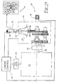
- Figure 1A is a highly schematic view of a vehicle drive train incorporating the present inventive four-position switch.
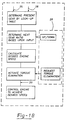
- Figure 1B is a highly schematic flow chart of an overall speed synchronization system incorporating the present inventive switch.
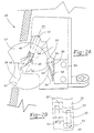
- Figure 2A is a cross-sectional view through a switch according to the present invention.
- Figure 2B shows a portion of the switch of Figure 2A.
- Figure 1 shows a vehicle drive 20 incorporating a manual stick shift 22 having a diagram 24 of the proper position for the stick shift 22 to achieve certain gear ratios, as known.
- An on/off switch 26 allows the operator to actuate or deactivate an engine speed synchronization system for assisting the driver in shifting the transmission.
- a four-position switch 28 allows the operator to provide an indication of whether an upshift or a downshift is next expected. The switch 28 also allows an operator to request torque elimination when the transmission is being moved to neutral. Switches 26 and 28 are mounted in stick shift 22.
- the stick shift 22 actuates gears within the transmission 30 as known.
- the stick shift 22 further sends communications from the switches 26 and 28 to an electronic control unit 32 for an engine 34.
- Electronic control unit 32 may be of a known type as commonly utilized to control the speed of engine 34 as by controlling the amount of fuel through fuel injectors 33.
- a known electronic control unit available under the trade name DDEC III, and available from Detroit Diesel Corporation may be modified to include additional control features relative to the speed synchronization and torque elimination features of this invention.
- the engine 34 has an output shaft 35 connected to a selectively actuated clutch 36 to drive an input shaft 37 of transmission 30.
- An output shaft 38 of the transmission 30 transmits drive to the drive axles of the vehicle.
- the ratio of the speeds between input shaft 37 and output shaft 38 is changed dependent on the speed of the transmission 30 as controlled by the stick shift 22.
- the stick shift 22 is utilized to move sliding members within transmission 30 to effect this gear change.
- a signal of whether the transmission is in neutral or engaged is also sent to ECU 32.
- the operator initially actuated the clutch 36 to break torque transmission between shafts 35 and 37. The operator is then able to easily move the transmission 30 to neutral.
- the operator controlled the speed of the engine 34 to attempt to synchronize the speed with that which the operator estimates would be necessary for achieving the necessary ratio, once transmission 30 is moved to the new gear ratio.
- This synchronization was largely dependent on the experience and skill of the driver, and required a good deal of "feel.”
- the driver reengages the transmission, again by actuating the clutch. Although the driver could actuate the clutch a single time to effect this shift, typically the driver would actuate the clutch twice, as some period of time was typically required to effect the engine change to the synchronized speed.
- FIG. 1B A system for achieving movement to neutral and speed synchronization without the driver having to actuate the clutch, or attempt to synchronize the speed manually is shown in Figure 1B.
- the ECU 32 calculates the currently engaged gear ratio based on the speed of shaft 35 and the speed of shaft 38. The ECU then determines what the next gear ratio would be based upon the shift intent signal received from the operator and the currently engaged gear. The ECU then determines the desired engine speed at the next gear ratio by multiplying the output speed on shaft 38 by the gear ratio at the next desired gear. The ECU is attempting to match the speed ratio. This results in a desired input engine speed to achieve a synchronized shift. In practice the determination might not be made until after the transmission is in neutral. Moreover, the determination is repeated periodically as transmission speed changes. However, the signal is typically received before movement to neutral as shown in the flowchart.
- the driver may request torque elimination through switch 28. If so, the ECU calculates a predicted zero torque parameter for the engine, such as fueling and begins to move the engine fueling to that predicted value.
- a predicted zero torque parameter for the engine such as fueling and begins to move the engine fueling to that predicted value.
- This system is disclosed in more detail in U.S. Patent Application Serial No. 08/508,155, entitled “Method and Apparatus for Assisting and Shifting Transmission to Neutral,” filed on the same day as this application.
- ECU 32 achieves the desired zero torque engine fueling, the operator is then able to move the transmission to neutral.
- a neutral signal is then sent to ECU 32.
- ECU 32 controls the engine speed to achieve the synchronized speed.
- the operator continues to move the gear into engagement, and once the gear is fully engaged a signal is sent to ECU 32 that the shift is complete. At that time, control of the system is returned to the operator.
- switch 28 The details of switch 28 are illustrated in Figures 2A and 2B.
- a switch body 39 rotates about an axis 40.
- a plunger 42 is received within body 39, and rides along surfaces of a contact body 44.
- Two holding portions 46 and 48 are defined for the plunger 42, which holds the switch body at one of two positions.
- the plunger 42 is held in one of the two positions 46 and 48.
- a switching recess 50 is formed in body 39 and includes two opposed ramped surfaces 52 and 54. These two surfaces allow the momentary movement to the torque elimination request position.
- a contact 55 contacts the switch body 39, and rides along surfaces 52 and 54.
- a second contact 53 rides in a cam surface 50' and provides a signal in one of the two positions identified by holding portions 46 or 48.
- An electrical circuit is completed, providing a signal to ECU 32. In the other position, there is an open circuit and no signal is sent.
- the signal from contact 53 is read as an indication that an upshift or a downshift is next expected. In the absence of such a signal the ECU will determine that the other shift direction is being indicated.
- the contact 55 With the switch in either the upshift or downshift position, the contact 55 is in the position shown in solid line. Should the operator desire to request torque elimination, the switch is rotated a further distance to the position shown in phantom at 57.
- the on/off switch 26 When an operator wishes to utilize the speed synchronization system, initially the on/off switch 26 is switched to on. The operator next selects whether upshifting or downshifting will next occur, and moves the switch 28 to the proper position.
- the driver may request torque elimination.
- the switch body is moved beyond the intent position to the torque elimination request position. The operator may do this merely by forcing the switch beyond its intent position.
- the operator is able to easily actuate this control with a simple finger pressure on the switch 28 as the operator holds the shift knob 22 to begin shifting transmission 30. No complex searching for separate switches is required, nor is any complex switch actuation required. Rather, a mere additional force on the switch body 39 is all that is required.
- the ECU 32 then achieves torque reduction. The operator is then able to move the transmission out of engagement to neutral with stick shift 22.
- ECU 32 then synchronizes the engine speed as described above. Once the engine speed is synchronized, the driver is able to reengage the transmission 30, and begin driving at the new gear. Once the electronic control unit 32 receives the signal that the gear is reengaged, control passes from the electronic control unit back to the operator. A driver may indicate skip shifting by repeatedly actuating and release the torque elimination request. ECU "counts" the actuations and adds the number of actuations to the current gear to determine the next gear.
Landscapes
- Engineering & Computer Science (AREA)
- Mechanical Engineering (AREA)
- Chemical & Material Sciences (AREA)
- Combustion & Propulsion (AREA)
- Transportation (AREA)
- General Engineering & Computer Science (AREA)
- Automation & Control Theory (AREA)
- Control Of Transmission Device (AREA)
- Arrangement Or Mounting Of Control Devices For Change-Speed Gearing (AREA)
- Gear-Shifting Mechanisms (AREA)
- Position Fixing By Use Of Radio Waves (AREA)
Abstract
Description
- This invention relates to a vehicle drive control system according to the preamble of
claim 1. - A control system of such kind is generally known.
- Furthermore, the invention relates to a method of operating a vehicle.
- Heavy vehicles equipped with manual transmissions typically are moved between several speeds at the control of a manual stick shift. An operator actuates a clutch to disengage torque transmission between the engine and the transmission and moves the transmission gears out of engagement. In moving the transmission to neutral, clutching is typically necessary since without clutching, there is "torque lock" on gears that transmit torque, holding them in position against axial movement. The clutch breaks torque lock, allowing the operator to easily move the gears out of engagement.
- The operator then typically releases the clutch pedal, and attempts to adjust engine speed to a synchronization speed ratio that will be required at the next gear ratio to which the driver is moving the transmission. A good deal of experience and feel is required to even approximate this speed. The driver must reduce the engine speed when upshifting and the driver needs to increase the engine speed when downshifting. Once the driver achieves the desired speed, the clutch is again disengaged and the driver engages the new gear.
- Even an experienced driver has difficulty exactly matching the synchronization speed ratio necessary at the next gear. Thus, the clutch is typically again actuated when reengaging the transmission to allow the transmission to compensate for the difference between the speed of the two transmission components that are being brought into engagement.
- Recently, heavy vehicles such as trucks have become equipped with more controls that require operator-intensive operations. In addition, there are more inexperienced truck drivers on the road than there have been in the past. Thus, the complex operations associated with shifting a manual transmission including clutching, and "feel" that an operator must have to achieve the speed ratio synchronization, have become more burdensome.
- It would be desirable to reduce the steps an operator of a vehicle must make on a routine basis while shifting gears. This is particularly true when several shifts are to be made in quick succession. It would be desirable to allow movement of the transmission to neutral for a shift without having to operate the clutch, to automatically synchronize the speed of the engine when the engine is in neutral, and then to allow re-engagement of the transmission without the clutch.
- The prior art has proposed systems to assist in eliminating the torque load on the vehicle without clutching. Moreover, the prior art has proposed systems that attempt to synchronize the engine speed with the speed ratio that will be needed to shift smoothly to the next gear ratio. These systems have been overly complex. In general, the systems are more conceptual rather than systems which deal with the practical problems such a system would face in the field. As an example, a practical system must provide the operator the option of utilizing the clutch and shifting through normal operations on any particular shift. An operator might be more inclined to utilize assisted shifting without clutching when several sequential shifts are to be made in series. That same operator might otherwise wish to use the clutch in normal operation for less frequent shifting. The proposed prior art systems do not adequately deal with this real world reality. Moreover, the proposed prior art systems do not provide a practical operator control for the system.
- WO 91/06903 suggests a steering stick which is part of a steering and transmission shift control mechanism. However, the steering stick is not for manually shifting a transmission.
- The object of the present invention is to provide a manually operable vehicle drive control system in which the steps the operator of the vehicle has to make on a routine basis are reduced while shifting between several speed ratios. Furthermore, a corresponding simple method of operating a vehicle should be proposed.
- This object is achieved by a vehicle drive control system according to
claim 1 and by a method of operating a vehicle according toclaim 7. - In a disclosed embodiment of this invention a vehicle drive comprises an engine and an associated electronic control unit. The engine has an output shaft which drives a multi-speed transmission through a clutch. An output shaft of the transmission drives the drive axles for the vehicle. The electronic control unit is operable to control engine speed to reduce torque on the transmission upon request by the operator, and further to synchronize the engine speed to that desired at the next gear as a gear shift occurs. A single switch allows a driver to send control signals to the electronic control unit. The driver is able to move a switch body between at least two positions, one of which provides an intent to upshift, and the other of which provides an indication that the driver intends to downshift. The switch body remains in either the upshift intention or downshift intention positions until moved by the operator. In either the upshift or downshift positions, the operator is allowed to over-travel the switch a small additional amount to provide an additional signal to the electronic control unit that torque elimination is desired.
- If the operator is making several sequential shifts, the switch may be left in the same position for all the shifts. As each shift is begun, the operator is able to request torque elimination to move the transmission to neutral. To request torque elimination, the operator merely moves the switch body a small additional amount beyond the upshift or downshift position. The operator is thus able to easily control the system and provide the required inputs to the electronic control unit.
- In a most preferred embodiment of this invention, the above-described switch is provided in the stick shift. The stick shift is also preferably provided with an on/off switch that either turns the system on or off. When off, the operator is left with complete control of the vehicle. When on, the four-position switch described above is constantly providing an indication of whether an upshift or a downshift is the next desired shift. As the operator begins to shift, the operator insures that the switch is in the proper position to indicate an upshift or a downshift. The electronic control unit determines that the next gear would be the next higher or the next lower depending on the operator intention provided from the switch. The electronic control unit determines the next expected gear based upon the operator intent signal. The electronic control unit then calculated a desired synchronization speed for the next gear. An operator is able to request skip shifts by repeatedly requesting torque elimination.
- A single switch providing the operator with the ability to send the signals simplifies driver operation. Separate switches might otherwise complicate the operation of the vehicle by the operator. Since the goal of the speed synchronization system is to reduce the complexity of vehicle operation, it would defeat that goal to provide a switch that is overly complex to use. As such, the inventive four-position switch disclosed and claimed in this invention provides valuable benefits.
- These and other features of the present invention can be best understood from the following specification and drawings, the following of which is a brief description.
- Figure 1A is a highly schematic view of a vehicle drive train incorporating the present inventive four-position switch.
- Figure 1B is a highly schematic flow chart of an overall speed synchronization system incorporating the present inventive switch.
- Figure 2A is a cross-sectional view through a switch according to the present invention.
- Figure 2B shows a portion of the switch of Figure 2A.
- Figure 1 shows a
vehicle drive 20 incorporating amanual stick shift 22 having a diagram 24 of the proper position for thestick shift 22 to achieve certain gear ratios, as known. An on/offswitch 26 allows the operator to actuate or deactivate an engine speed synchronization system for assisting the driver in shifting the transmission. A four-position switch 28, allows the operator to provide an indication of whether an upshift or a downshift is next expected. Theswitch 28 also allows an operator to request torque elimination when the transmission is being moved to neutral.Switches stick shift 22. - The
stick shift 22 actuates gears within thetransmission 30 as known. Thestick shift 22 further sends communications from theswitches electronic control unit 32 for anengine 34.Electronic control unit 32 may be of a known type as commonly utilized to control the speed ofengine 34 as by controlling the amount of fuel throughfuel injectors 33. A known electronic control unit available under the trade name DDEC III, and available from Detroit Diesel Corporation may be modified to include additional control features relative to the speed synchronization and torque elimination features of this invention. - The
engine 34 has anoutput shaft 35 connected to a selectively actuated clutch 36 to drive aninput shaft 37 oftransmission 30. Anoutput shaft 38 of thetransmission 30 transmits drive to the drive axles of the vehicle. The ratio of the speeds betweeninput shaft 37 andoutput shaft 38 is changed dependent on the speed of thetransmission 30 as controlled by thestick shift 22. As is known, when an operator wishes to move thetransmission 30 to a new gear ratio, thestick shift 22 is utilized to move sliding members withintransmission 30 to effect this gear change. A signal of whether the transmission is in neutral or engaged is also sent toECU 32. In the prior art, the operator initially actuated the clutch 36 to break torque transmission betweenshafts transmission 30 to neutral. Once in neutral, the operator controlled the speed of theengine 34 to attempt to synchronize the speed with that which the operator estimates would be necessary for achieving the necessary ratio, oncetransmission 30 is moved to the new gear ratio. This synchronization was largely dependent on the experience and skill of the driver, and required a good deal of "feel." Once the driver estimated that the engine was approximately the right speed, the driver reengages the transmission, again by actuating the clutch. Although the driver could actuate the clutch a single time to effect this shift, typically the driver would actuate the clutch twice, as some period of time was typically required to effect the engine change to the synchronized speed. - A system for achieving movement to neutral and speed synchronization without the driver having to actuate the clutch, or attempt to synchronize the speed manually is shown in Figure 1B. The
ECU 32 calculates the currently engaged gear ratio based on the speed ofshaft 35 and the speed ofshaft 38. The ECU then determines what the next gear ratio would be based upon the shift intent signal received from the operator and the currently engaged gear. The ECU then determines the desired engine speed at the next gear ratio by multiplying the output speed onshaft 38 by the gear ratio at the next desired gear. The ECU is attempting to match the speed ratio. This results in a desired input engine speed to achieve a synchronized shift. In practice the determination might not be made until after the transmission is in neutral. Moreover, the determination is repeated periodically as transmission speed changes. However, the signal is typically received before movement to neutral as shown in the flowchart. - When the driver begins to move the transmission to neutral, the driver may request torque elimination through
switch 28. If so, the ECU calculates a predicted zero torque parameter for the engine, such as fueling and begins to move the engine fueling to that predicted value. This system is disclosed in more detail in U.S. Patent Application Serial No. 08/508,155, entitled "Method and Apparatus for Assisting and Shifting Transmission to Neutral," filed on the same day as this application. WhenECU 32 achieves the desired zero torque engine fueling, the operator is then able to move the transmission to neutral. - A neutral signal is then sent to
ECU 32. At that time,ECU 32 controls the engine speed to achieve the synchronized speed. The operator continues to move the gear into engagement, and once the gear is fully engaged a signal is sent toECU 32 that the shift is complete. At that time, control of the system is returned to the operator. - The above is intended as a simplified description of a complicated system. Details of the systems are disclosed in several co-pending patent applications. A preferred switch to provide the neutral and gear engaged signals is disclosed in co-pending U.S. Patent Application Serial No. 08/508,067, entitled "Two-Position Neutral Switch for Multi-Speed Transmission." During an upshift, it may be desirable to add an additional decay to the engine speed to quickly reduce the engine speed. Such a system is disclosed in co-pending U.S. Patent Application Serial No. 08/508,111, which is entitled "Engine Speed Retardation On a Transmission Upshift." The engine speed synchronization system is disclosed more fully in co-pending U.S. Patent Application Serial No. 08/508,135, which is entitled "Engine Speed Synchronization System for Assisting a Manual Transmission Shift." Other features of the system are generally disclosed in co-pending U.S. Patent Applications Serial No. 08/507,996, entitled "Automatic Range Shift for Multi-Speed Transmission;" and Serial No. 08/508,156; entitled "Combined System for Assisting Shifting of Manual Transmission Without Clutching. Finally, the general switching parameters of allowing selective shift intent and torque elimination are disclosed in co-pending Patent Application Serial No. 08/508,307, entitled "Operator Input System for Gear Shift Assist Mechanism." The present invention is directed to an improvement of the switch system in that application which reduces the complexity of the input operation for the operator. All of the above applications are filed on the same day as this application.
- The details of
switch 28 are illustrated in Figures 2A and 2B. As shown, aswitch body 39 rotates about anaxis 40. Aplunger 42 is received withinbody 39, and rides along surfaces of acontact body 44. Two holdingportions plunger 42, which holds the switch body at one of two positions. Theplunger 42 is held in one of the twopositions recess 50 is formed inbody 39 and includes two opposed rampedsurfaces - A
contact 55 contacts theswitch body 39, and rides alongsurfaces second contact 53 rides in a cam surface 50' and provides a signal in one of the two positions identified by holdingportions ECU 32. In the other position, there is an open circuit and no signal is sent. The signal fromcontact 53 is read as an indication that an upshift or a downshift is next expected. In the absence of such a signal the ECU will determine that the other shift direction is being indicated. With the switch in either the upshift or downshift position, thecontact 55 is in the position shown in solid line. Should the operator desire to request torque elimination, the switch is rotated a further distance to the position shown in phantom at 57. In this position, thecontact 55 is forced downwardly to the position shown at 56 andball 58 is forced downwardly completing a contact within aswitch box 59. A similar switch, not shown, is actuated bycontact 53 to complete that circuit. In one of the twopositions contact 53 actuates its switch. Theplunger 42 is forced farther inwardly during this movement, compressingspring 49. This contact provides a separate signal that torque elimination is being requested. The ramp surfaces 52 and 54 guide thecontact 55 downwardly as long as an operator holds theswitch body 39 atposition 57. Once the operator releases theswitch body 39, the spring force of thecontact 55 and spring will return theswitch body 39 to the non-torque elimination requested position. Theswitch body 39 remains in either the upshift intent or downshift intent positions until moved. Stops are also provided betweenbody 39 andbody 44 to prevent overtravel in the torque elimination request position. - When an operator wishes to utilize the speed synchronization system, initially the on/off
switch 26 is switched to on. The operator next selects whether upshifting or downshifting will next occur, and moves theswitch 28 to the proper position. When the driver wishes to begin actuating a shift, the driver may request torque elimination. The switch body is moved beyond the intent position to the torque elimination request position. The operator may do this merely by forcing the switch beyond its intent position. The operator is able to easily actuate this control with a simple finger pressure on theswitch 28 as the operator holds theshift knob 22 to begin shiftingtransmission 30. No complex searching for separate switches is required, nor is any complex switch actuation required. Rather, a mere additional force on theswitch body 39 is all that is required. TheECU 32 then achieves torque reduction. The operator is then able to move the transmission out of engagement to neutral withstick shift 22. -
ECU 32 then synchronizes the engine speed as described above. Once the engine speed is synchronized, the driver is able to reengage thetransmission 30, and begin driving at the new gear. Once theelectronic control unit 32 receives the signal that the gear is reengaged, control passes from the electronic control unit back to the operator. A driver may indicate skip shifting by repeatedly actuating and release the torque elimination request. ECU "counts" the actuations and adds the number of actuations to the current gear to determine the next gear.
Claims (10)
- A vehicle drive control system comprising:characterized in that the system comprises furtheran engine (34) having an output shaft (35);an electronic control unit (32) for controlling the output speed of said engine output shaft (35);a multi-speed transmission (30) connected to be driven by said engine output shaft (35) through several speed ratios;a manual stick shift (22) operable by an operator to manually shift said transmission (30) between said several speed ratios;a clutch (36) selectively actuated by the operator and positioned between said engine and said transmission;an operator input control switch (28) by which the operator provides an indication to said electronic control unit of whether an upshift or a downshift is to be initiated, and by which the operator is able to request torque elimination as the operator begins to move the transmission to neutraland in that said electronic control unit (32) is operableto receive signals from said input control switch (28) and determine a desired engine speed at a next gear based upon said indication from the operator,to control said engine to achieve said desired engine speed, andto reduce torque to allow the operator to move said transmission to a neutral position when said torque elimination request signal is received by said electronic control unit;said input control switch (28) having a switch body (39) and being configured such that it is held in respective ones of at least two positions to indicate upshift intent and downshift intent, andsaid switch body (39) remaining in said position until moved by the operator;said torque elimination request being initiated by the operator moving said switch body (39) from said upshift or downshift intent position to torque elimination request position; andsaid switch body (39) returning to said upshift or downshift position from said torque elimination request position once the operator has released said switch body (39).
- A control system as recited in Claim 1, wherein said switch body (39) rotates about an axis (40) between two positions indicating upshift intent and downshift intent, and wherein said switch body is rotatable beyond either of said positions to said torque elimination request position when a force is applied to the switch body by the operator.
- A control system as recited in Claim 2, wherein a contact member (55) provides an electric signal to said electronic control unit (32) when said switch body (39) is in one of said upshift intent or downshift intent positions, and a second circuit (59) being actuated to provide said torque elimination request when said switch body (39) is moved beyond either said upshift intent and said downshift intent positions.
- A control system as recited in Claim 3, wherein said operator is further provided with a second switch (26) that allows deactivation of said speed synchronization function of said electronic control unit (32) to allow said operator to manually shift said transmission by utilizing said clutch (36).
- A control system as recited in Claim 4, wherein said second switch (26) and said operator input control switch (28) are both received in said manual stick shift (22).
- A control system as recited in Claim 1, wherein said operator input control switch (28) is received in said manual stick shift (22).
- A method of operating a vehicle comprising the steps of:(a) providinga vehicle drive including an engine (34) having an output shaft (35),an electronic control unit (32) for controlling the speed of said engine output shaft,a multi-speed transmission (30) selectively driven by said engine output shaft (35), said multi-speed transmission being operable to be moved between selected speed ratios to control the ratio between an output speed of said transmission (30) and the speed of said engine output shaft (35),a clutch (36) disposed between said engine output shaft (35) and said transmission (30) to allow breaking of the rotational drive transmitted from said engine (34) to said transmission,a manual stick shift (22) operable by an operator to manually shift said transmission (30) between said speed ratios, characterised by further providing(b) a single operator input switch (28) by which the operatorprovides an indication to said electronic control unit (32) of when an upshift or a downshift is to be expected as the next shift, andis able to request torque elimination from the electronic control unit (32) such that said transmission (30) may be moved to neutral without actuating said clutch (36),said electronic control unit (32) being operable to receive said indication of an upshift or a downshift, andto determine a desired engine speed at a next gear based upon said indication and the currently engaged gear;(c) providing an indication through said operator input switch (20) of whether an upshift or a downshift is expected as the next gear shift by positioning said operator input switch (28) in either an upshift or a downshift position;(d) providing an indication that torque elimination is desired from said switch by manually moving said switch (28) from said upshift or downshift position into a torque elimination request position;(e) reducing the torque load from said engine (34) on said transmission (30) using said electronic control unit (32), upon receiving a request for torque elimination;(f) releasing said switch (28) from said torque elimination request position and allowing said switch to return to said shift intent position;(g) moving said transmission (30) to a neutral position by manually moving said stick shift (22);(h) providing a signal to said electronic control unit (32) that said transmission (30) is in neutral;(i) identifying a desired engine speed value at the next gear based upon said driver indication of whether an upshift or a downshift is next expected;(j) using said electronic control unit (32) to begin moving said engine speed to said desired engine speed; and(k) engaging said transmission (30) in the next selected gear by manually moving said stick shift (22) after speed synchronization to engage said gear.
- A method as recited in Claim 7, wherein said switch (28) is rotatable between said upshift intent and said downshift intent positions, and step (d) is performed by rotating said switch beyond said upshift intent position or said downshift intent position to said torque elimination request position,
and wherein said switch (28) is biased into said upshift intent position or said downshift intent position from said torque elimination request position such that upon release by the operator, step (f) includes said switch automatically returning to said upshift intent position or said downshift intent position from said torque elimination request position. - A method as recited in Claim 7, wherein the method includes the further step of providing an on/off switch (26), that allows the operator to enable or disable the speed control for assisting shifting.
- A method as recited in Claim 9, wherein said single operator input switch (28) and said on/off switch (26) are both provided in said manual stick shift (22).
Applications Claiming Priority (3)
| Application Number | Priority Date | Filing Date | Title |
|---|---|---|---|
| US508153 | 1995-07-27 | ||
| US08/508,153 US5779592A (en) | 1995-07-27 | 1995-07-27 | Four position switch for shift assist system |
| PCT/US1996/012268 WO1997005404A1 (en) | 1995-07-27 | 1996-07-25 | Four-position switch for shift assist system |
Publications (2)
| Publication Number | Publication Date |
|---|---|
| EP0838000A1 EP0838000A1 (en) | 1998-04-29 |
| EP0838000B1 true EP0838000B1 (en) | 2001-05-16 |
Family
ID=24021606
Family Applications (1)
| Application Number | Title | Priority Date | Filing Date |
|---|---|---|---|
| EP96925510A Expired - Lifetime EP0838000B1 (en) | 1995-07-27 | 1996-07-25 | Four-position switch for shift assist system |
Country Status (6)
| Country | Link |
|---|---|
| US (1) | US5779592A (en) |
| EP (1) | EP0838000B1 (en) |
| AU (1) | AU712686B2 (en) |
| BR (1) | BR9609828A (en) |
| DE (1) | DE69612851T2 (en) |
| WO (1) | WO1997005404A1 (en) |
Families Citing this family (2)
| Publication number | Priority date | Publication date | Assignee | Title |
|---|---|---|---|---|
| US6007455A (en) * | 1997-02-25 | 1999-12-28 | Eaton Corporation | Semi-automatic shift implementation with automatic engine control enable switch |
| GB2371839A (en) * | 2001-02-01 | 2002-08-07 | Eaton Corp | Control for selecting automated transmission system shift strategy |
Family Cites Families (18)
| Publication number | Priority date | Publication date | Assignee | Title |
|---|---|---|---|---|
| DE3045840A1 (en) * | 1980-12-05 | 1982-07-08 | Volkswagenwerk Ag, 3180 Wolfsburg | DEVICE FOR CLUTCH AND SYNCHRONIZER-FREE SWITCHING OF A STEPPED TRANSMISSION OF VEHICLE DRIVES |
| US4425620A (en) * | 1981-01-28 | 1984-01-10 | Steiger Tractor, Inc. | Electrical control for power shift transmission |
| FR2635597B1 (en) * | 1988-08-18 | 1994-05-13 | Renault Regie Nale Usines | METHOD FOR CONTROLLING THE TORQUE MODULATION OF A HEAT ENGINE ASSOCIATED WITH AN AUTOMATIC TRANSMISSION |
| AU6338790A (en) * | 1989-08-25 | 1991-04-03 | Scandmec Mecania Ab | Actuating lever |
| AU640121B2 (en) * | 1989-11-02 | 1993-08-19 | Caterpillar Inc. | Steering and transmission shifting control mechanism |
| US5172603A (en) * | 1991-05-03 | 1992-12-22 | Macinnis Richard F | Electrically actuated shifting method and apparatus |
| JP3312918B2 (en) * | 1991-10-09 | 2002-08-12 | マツダ株式会社 | Control device for engine and automatic transmission |
| GB2262787B (en) * | 1991-12-24 | 1995-01-04 | Gen Motors France | Method and apparatus for managing engine torque |
| DE4204223A1 (en) * | 1992-02-13 | 1993-08-19 | Zahnradfabrik Friedrichshafen | CONTROL STICK FOR SWITCHING OR OPERATING COMPONENTS OF A COMMERCIAL VEHICLE |
| DE4204401A1 (en) * | 1992-02-14 | 1993-08-19 | Bosch Gmbh Robert | DEVICE FOR CONTROLLING THE OUTPUT TORQUE OF AN AUTOMATIC MANUAL TRANSMISSION |
| JPH0640272A (en) * | 1992-07-22 | 1994-02-15 | Jatco Corp | Control device for engine and automatic transmission |
| US5506771A (en) * | 1992-08-27 | 1996-04-09 | Eaton Corporation | Start gear ratio control system and method |
| GB9219101D0 (en) * | 1992-09-09 | 1992-10-21 | Automotive Products Plc | A clutch control system |
| GB9301294D0 (en) * | 1993-01-23 | 1993-03-17 | Eaton Corp | Gear butt warning |
| US5436419A (en) * | 1993-04-16 | 1995-07-25 | Sauer Inc. | Neutral start switch and backup alarm switch, and method of assembling the same for a manual displacement control for a hydrostatic transmission |
| US5388476A (en) * | 1993-06-15 | 1995-02-14 | Agco Corporation | Gearshift mechanism |
| US5429559A (en) * | 1993-09-22 | 1995-07-04 | Eaton Corporation | Forced engagement logic |
| US5487004A (en) * | 1993-10-29 | 1996-01-23 | Eaton Corporation | Control system/method for automated mechanical transmission systems |
-
1995
- 1995-07-27 US US08/508,153 patent/US5779592A/en not_active Expired - Lifetime
-
1996
- 1996-07-25 BR BR9609828A patent/BR9609828A/en not_active IP Right Cessation
- 1996-07-25 DE DE69612851T patent/DE69612851T2/en not_active Expired - Fee Related
- 1996-07-25 WO PCT/US1996/012268 patent/WO1997005404A1/en not_active Ceased
- 1996-07-25 AU AU66001/96A patent/AU712686B2/en not_active Ceased
- 1996-07-25 EP EP96925510A patent/EP0838000B1/en not_active Expired - Lifetime
Also Published As
| Publication number | Publication date |
|---|---|
| WO1997005404A1 (en) | 1997-02-13 |
| DE69612851D1 (en) | 2001-06-21 |
| AU712686B2 (en) | 1999-11-11 |
| BR9609828A (en) | 1999-07-06 |
| US5779592A (en) | 1998-07-14 |
| EP0838000A1 (en) | 1998-04-29 |
| AU6600196A (en) | 1997-02-26 |
| DE69612851T2 (en) | 2001-11-15 |
Similar Documents
| Publication | Publication Date | Title |
|---|---|---|
| US5569115A (en) | Engine speed synchronization system for assisting in manual transmission shifting | |
| US5571059A (en) | Operator input system for gear shift assist mechanism | |
| US5984828A (en) | Control methods for a shift by wire vehicle transmission | |
| US6145398A (en) | Electronically controlled shift system for a manual transmission | |
| EP0898518B1 (en) | Shift by wire transmission system | |
| US6881175B2 (en) | Combined control device for the parking brake and park lock function of motor vehicles | |
| JPH11141663A (en) | Device for controlling an automatic transmission of a car | |
| EP1130292B1 (en) | Engine overrun prevention system and method for automatic transmission of a motor vehicle | |
| JPH11153224A (en) | Shift rail detent mechanism | |
| JPH11241765A (en) | VEHICLE TRANSMISSION DEVICE AND CONTROL METHOD THEREOF | |
| GB2243655A (en) | Arrangement for actuating a motor vehicle friction clutch disconnects engine accelerator control until after gearshift | |
| US5022509A (en) | Semiautomatic shifter for a motor vehicle | |
| US7200477B2 (en) | Driver-aid method and device for shifting gears in an automatic transmission | |
| JPH09324852A (en) | Transmission control device for vehicle transmission | |
| US5779592A (en) | Four position switch for shift assist system | |
| JP2011140965A (en) | Control device and control method of automatic transmission | |
| JPH09177955A (en) | Method and control device for mechanical automatic transmission | |
| JP2000088012A (en) | Automatic clutch device for geared transmission | |
| EP1134457B1 (en) | Method for reducing driver workload in a vehicle equipped with a manually shifted gearbox | |
| US20030097892A1 (en) | Shift lever and method for maneuvering an automatic transmission | |
| JP2652634B2 (en) | Clutch control method | |
| JPH07208590A (en) | Speed change selecting circuit used for semiautomatic transmission | |
| JPH07217729A (en) | Electronic shift device | |
| JP2000337406A (en) | Automatic clutch system for retrofit | |
| EP1309465A1 (en) | Shift lever and method for manoeuvring an automatic transmission |
Legal Events
| Date | Code | Title | Description |
|---|---|---|---|
| PUAI | Public reference made under article 153(3) epc to a published international application that has entered the european phase |
Free format text: ORIGINAL CODE: 0009012 |
|
| 17P | Request for examination filed |
Effective date: 19980227 |
|
| AK | Designated contracting states |
Kind code of ref document: A1 Designated state(s): DE FR GB |
|
| 17Q | First examination report despatched |
Effective date: 19990428 |
|
| GRAG | Despatch of communication of intention to grant |
Free format text: ORIGINAL CODE: EPIDOS AGRA |
|
| GRAG | Despatch of communication of intention to grant |
Free format text: ORIGINAL CODE: EPIDOS AGRA |
|
| GRAH | Despatch of communication of intention to grant a patent |
Free format text: ORIGINAL CODE: EPIDOS IGRA |
|
| RAP1 | Party data changed (applicant data changed or rights of an application transferred) |
Owner name: ZF MERITOR, LLC |
|
| GRAH | Despatch of communication of intention to grant a patent |
Free format text: ORIGINAL CODE: EPIDOS IGRA |
|
| GRAA | (expected) grant |
Free format text: ORIGINAL CODE: 0009210 |
|
| AK | Designated contracting states |
Kind code of ref document: B1 Designated state(s): DE FR GB |
|
| REF | Corresponds to: |
Ref document number: 69612851 Country of ref document: DE Date of ref document: 20010621 |
|
| ET | Fr: translation filed | ||
| REG | Reference to a national code |
Ref country code: GB Ref legal event code: IF02 |
|
| PLBE | No opposition filed within time limit |
Free format text: ORIGINAL CODE: 0009261 |
|
| STAA | Information on the status of an ep patent application or granted ep patent |
Free format text: STATUS: NO OPPOSITION FILED WITHIN TIME LIMIT |
|
| 26N | No opposition filed | ||
| PGFP | Annual fee paid to national office [announced via postgrant information from national office to epo] |
Ref country code: GB Payment date: 20070725 Year of fee payment: 12 |
|
| PGFP | Annual fee paid to national office [announced via postgrant information from national office to epo] |
Ref country code: FR Payment date: 20070710 Year of fee payment: 12 |
|
| PGFP | Annual fee paid to national office [announced via postgrant information from national office to epo] |
Ref country code: DE Payment date: 20080807 Year of fee payment: 13 |
|
| GBPC | Gb: european patent ceased through non-payment of renewal fee |
Effective date: 20080725 |
|
| REG | Reference to a national code |
Ref country code: FR Ref legal event code: ST Effective date: 20090331 |
|
| PG25 | Lapsed in a contracting state [announced via postgrant information from national office to epo] |
Ref country code: GB Free format text: LAPSE BECAUSE OF NON-PAYMENT OF DUE FEES Effective date: 20080725 |
|
| PG25 | Lapsed in a contracting state [announced via postgrant information from national office to epo] |
Ref country code: FR Free format text: LAPSE BECAUSE OF NON-PAYMENT OF DUE FEES Effective date: 20080731 |
|
| PG25 | Lapsed in a contracting state [announced via postgrant information from national office to epo] |
Ref country code: DE Free format text: LAPSE BECAUSE OF NON-PAYMENT OF DUE FEES Effective date: 20100202 |