EP0837953B1 - Laminated material - Google Patents
Laminated material Download PDFInfo
- Publication number
- EP0837953B1 EP0837953B1 EP96923838A EP96923838A EP0837953B1 EP 0837953 B1 EP0837953 B1 EP 0837953B1 EP 96923838 A EP96923838 A EP 96923838A EP 96923838 A EP96923838 A EP 96923838A EP 0837953 B1 EP0837953 B1 EP 0837953B1
- Authority
- EP
- European Patent Office
- Prior art keywords
- lead
- material according
- layer
- laminate material
- copper
- Prior art date
- Legal status (The legal status is an assumption and is not a legal conclusion. Google has not performed a legal analysis and makes no representation as to the accuracy of the status listed.)
- Expired - Lifetime
Links
Images
Classifications
-
- C—CHEMISTRY; METALLURGY
- C23—COATING METALLIC MATERIAL; COATING MATERIAL WITH METALLIC MATERIAL; CHEMICAL SURFACE TREATMENT; DIFFUSION TREATMENT OF METALLIC MATERIAL; COATING BY VACUUM EVAPORATION, BY SPUTTERING, BY ION IMPLANTATION OR BY CHEMICAL VAPOUR DEPOSITION, IN GENERAL; INHIBITING CORROSION OF METALLIC MATERIAL OR INCRUSTATION IN GENERAL
- C23C—COATING METALLIC MATERIAL; COATING MATERIAL WITH METALLIC MATERIAL; SURFACE TREATMENT OF METALLIC MATERIAL BY DIFFUSION INTO THE SURFACE, BY CHEMICAL CONVERSION OR SUBSTITUTION; COATING BY VACUUM EVAPORATION, BY SPUTTERING, BY ION IMPLANTATION OR BY CHEMICAL VAPOUR DEPOSITION, IN GENERAL
- C23C14/00—Coating by vacuum evaporation, by sputtering or by ion implantation of the coating forming material
- C23C14/06—Coating by vacuum evaporation, by sputtering or by ion implantation of the coating forming material characterised by the coating material
- C23C14/14—Metallic material, boron or silicon
- C23C14/16—Metallic material, boron or silicon on metallic substrates or on substrates of boron or silicon
- C23C14/165—Metallic material, boron or silicon on metallic substrates or on substrates of boron or silicon by cathodic sputtering
-
- C—CHEMISTRY; METALLURGY
- C23—COATING METALLIC MATERIAL; COATING MATERIAL WITH METALLIC MATERIAL; CHEMICAL SURFACE TREATMENT; DIFFUSION TREATMENT OF METALLIC MATERIAL; COATING BY VACUUM EVAPORATION, BY SPUTTERING, BY ION IMPLANTATION OR BY CHEMICAL VAPOUR DEPOSITION, IN GENERAL; INHIBITING CORROSION OF METALLIC MATERIAL OR INCRUSTATION IN GENERAL
- C23C—COATING METALLIC MATERIAL; COATING MATERIAL WITH METALLIC MATERIAL; SURFACE TREATMENT OF METALLIC MATERIAL BY DIFFUSION INTO THE SURFACE, BY CHEMICAL CONVERSION OR SUBSTITUTION; COATING BY VACUUM EVAPORATION, BY SPUTTERING, BY ION IMPLANTATION OR BY CHEMICAL VAPOUR DEPOSITION, IN GENERAL
- C23C14/00—Coating by vacuum evaporation, by sputtering or by ion implantation of the coating forming material
- C23C14/06—Coating by vacuum evaporation, by sputtering or by ion implantation of the coating forming material characterised by the coating material
- C23C14/14—Metallic material, boron or silicon
- C23C14/16—Metallic material, boron or silicon on metallic substrates or on substrates of boron or silicon
-
- C—CHEMISTRY; METALLURGY
- C22—METALLURGY; FERROUS OR NON-FERROUS ALLOYS; TREATMENT OF ALLOYS OR NON-FERROUS METALS
- C22C—ALLOYS
- C22C9/00—Alloys based on copper
- C22C9/08—Alloys based on copper with lead as the next major constituent
-
- F—MECHANICAL ENGINEERING; LIGHTING; HEATING; WEAPONS; BLASTING
- F16—ENGINEERING ELEMENTS AND UNITS; GENERAL MEASURES FOR PRODUCING AND MAINTAINING EFFECTIVE FUNCTIONING OF MACHINES OR INSTALLATIONS; THERMAL INSULATION IN GENERAL
- F16C—SHAFTS; FLEXIBLE SHAFTS; ELEMENTS OR CRANKSHAFT MECHANISMS; ROTARY BODIES OTHER THAN GEARING ELEMENTS; BEARINGS
- F16C33/00—Parts of bearings; Special methods for making bearings or parts thereof
- F16C33/02—Parts of sliding-contact bearings
- F16C33/04—Brasses; Bushes; Linings
- F16C33/06—Sliding surface mainly made of metal
- F16C33/12—Structural composition; Use of special materials or surface treatments, e.g. for rust-proofing
- F16C33/122—Multilayer structures of sleeves, washers or liners
-
- F—MECHANICAL ENGINEERING; LIGHTING; HEATING; WEAPONS; BLASTING
- F16—ENGINEERING ELEMENTS AND UNITS; GENERAL MEASURES FOR PRODUCING AND MAINTAINING EFFECTIVE FUNCTIONING OF MACHINES OR INSTALLATIONS; THERMAL INSULATION IN GENERAL
- F16L—PIPES; JOINTS OR FITTINGS FOR PIPES; SUPPORTS FOR PIPES, CABLES OR PROTECTIVE TUBING; MEANS FOR THERMAL INSULATION IN GENERAL
- F16L33/00—Arrangements for connecting hoses to rigid members; Rigid hose connectors, i.e. single members engaging both hoses
- F16L33/02—Hose-clips
- F16L33/12—Hose-clips with a pivoted or swinging tightening or securing member, e.g. toggle lever
-
- F—MECHANICAL ENGINEERING; LIGHTING; HEATING; WEAPONS; BLASTING
- F16—ENGINEERING ELEMENTS AND UNITS; GENERAL MEASURES FOR PRODUCING AND MAINTAINING EFFECTIVE FUNCTIONING OF MACHINES OR INSTALLATIONS; THERMAL INSULATION IN GENERAL
- F16C—SHAFTS; FLEXIBLE SHAFTS; ELEMENTS OR CRANKSHAFT MECHANISMS; ROTARY BODIES OTHER THAN GEARING ELEMENTS; BEARINGS
- F16C2204/00—Metallic materials; Alloys
- F16C2204/10—Alloys based on copper
- F16C2204/16—Alloys based on copper with lead as the next major constituent
-
- Y—GENERAL TAGGING OF NEW TECHNOLOGICAL DEVELOPMENTS; GENERAL TAGGING OF CROSS-SECTIONAL TECHNOLOGIES SPANNING OVER SEVERAL SECTIONS OF THE IPC; TECHNICAL SUBJECTS COVERED BY FORMER USPC CROSS-REFERENCE ART COLLECTIONS [XRACs] AND DIGESTS
- Y10—TECHNICAL SUBJECTS COVERED BY FORMER USPC
- Y10S—TECHNICAL SUBJECTS COVERED BY FORMER USPC CROSS-REFERENCE ART COLLECTIONS [XRACs] AND DIGESTS
- Y10S384/00—Bearings
- Y10S384/90—Cooling or heating
- Y10S384/912—Metallic
-
- Y—GENERAL TAGGING OF NEW TECHNOLOGICAL DEVELOPMENTS; GENERAL TAGGING OF CROSS-SECTIONAL TECHNOLOGIES SPANNING OVER SEVERAL SECTIONS OF THE IPC; TECHNICAL SUBJECTS COVERED BY FORMER USPC CROSS-REFERENCE ART COLLECTIONS [XRACs] AND DIGESTS
- Y10—TECHNICAL SUBJECTS COVERED BY FORMER USPC
- Y10T—TECHNICAL SUBJECTS COVERED BY FORMER US CLASSIFICATION
- Y10T428/00—Stock material or miscellaneous articles
- Y10T428/12—All metal or with adjacent metals
- Y10T428/12493—Composite; i.e., plural, adjacent, spatially distinct metal components [e.g., layers, joint, etc.]
- Y10T428/12701—Pb-base component
-
- Y—GENERAL TAGGING OF NEW TECHNOLOGICAL DEVELOPMENTS; GENERAL TAGGING OF CROSS-SECTIONAL TECHNOLOGIES SPANNING OVER SEVERAL SECTIONS OF THE IPC; TECHNICAL SUBJECTS COVERED BY FORMER USPC CROSS-REFERENCE ART COLLECTIONS [XRACs] AND DIGESTS
- Y10—TECHNICAL SUBJECTS COVERED BY FORMER USPC
- Y10T—TECHNICAL SUBJECTS COVERED BY FORMER US CLASSIFICATION
- Y10T428/00—Stock material or miscellaneous articles
- Y10T428/12—All metal or with adjacent metals
- Y10T428/12493—Composite; i.e., plural, adjacent, spatially distinct metal components [e.g., layers, joint, etc.]
- Y10T428/12771—Transition metal-base component
- Y10T428/12861—Group VIII or IB metal-base component
- Y10T428/12903—Cu-base component
- Y10T428/12917—Next to Fe-base component
- Y10T428/12924—Fe-base has 0.01-1.7% carbon [i.e., steel]
Abstract
Description
Die Erfindung betrifft einen Schichtwerkstoff mit einem unmittelbar auf einem Trägerwerkstoff mittels Sputtern aufgebrachten Lagerwerkstoff, der einen Matrixwerkstoff aus Kupfer oder Kupferbasislegierung mit feinverteilten Bleieinlagerungen aufweist.The invention relates to a layer material with one directly on one Carrier material applied by means of sputtering, the one Matrix material made of copper or copper-based alloy with finely divided Has lead storage.
Werkstoffe auf Kupferbasis mit unterschiedlichen Legierungselementen finden breite Anwendung als hochbelastbare Gleitlagerwerkstoffe in modernen Verbrennungsmotoren. Ihre hohe Festigkeit zeichnet sie für den Einsatz als Pleuellager, Hauptlager, Kolbenbolzen- und Kipphebelbuchsen sowie für den Einsatz als Getriebeteile oder als Bauteile im allgemeinen Maschinenbau aus. Mit zunehmendem Bleigehalt und z.B. abnehmendem Zinngehalt nimmt die Anpassungsfähigkeit und Verträglichkeit mit dem Gegenläufer zu, wobei aber die Korrosionsbeständigkeit und Festigkeit deutlich abnimmt. Für den Einsatz als Pleuel- oder Hauptlager im modernen Motorenbau werden diese Lager deshalb meist mit einer, die Korrosionsbeständigkeit deutlich steigernden galvanischen Drittschicht versehen. So gestaltete Pleuellager- bzw. Kurbelwellenlager finden millionenfach Anwendung im Motorenbau. Der Dreischichtaufbau dieser Schichtwerkstoffe ist jedoch verfahrenstechnisch äußerst aufwendig.Find copper-based materials with different alloying elements widely used as heavy-duty plain bearing materials in modern Internal combustion engines. Their high strength distinguishes them for use as Connecting rod bearings, main bearings, piston pin and rocker arm bushings as well as for the Use as gear parts or as components in general mechanical engineering. With increasing lead content and e.g. decreasing tin content takes the Adaptability and compatibility with the counterpart, too the corrosion resistance and strength decrease significantly. For use these bearings are used as connecting rod or main bearings in modern engine construction therefore usually with one that significantly increases the corrosion resistance galvanic third layer. Conrod bearing or Crankshaft bearings are used millions of times in engine construction. The However, the three-layer structure of these layer materials is procedural extremely complex.
Aus Gleitlager, E. Schmidt, R. Weber, 1953, S. 192 ist es bekannt, daß eine eindeutige Korrelation zwischen der Gefügeausbildung bzw. Gefügegestalt und dem Korrosionsverhalten bei Bleibronzen besteht. Dies bedeutet, daß je feinkristalliner das Gefüge ist und damit auch je feiner die Bleiteilchen innerhalb der Matrix verteilt sind, der Werkstoff umso korrosionsbeständiger ist. Daneben wirkt sich eine möglichst feine globulistische Struktur der Bleiteilchen vorteilhaft aus.From Gleitlager, E. Schmidt, R. Weber, 1953, p. 192 it is known that a clear correlation between the structure or structure and the corrosion behavior of lead bronzes. This means that ever the structure is finely crystalline and therefore the finer the lead particles are distributed within the matrix, the material is all the more corrosion-resistant is. In addition, the globulistic structure of the Lead particles advantageous.
Um dem Verlust an Festigkeit der Matrix mit zunehmendem Bleigehalt wirksam zu begegnen, wird eine möglichst feinkristalline Struktur angetrebt, deren Realisierung aber z.B. auf gießtechnischem Wege nach unten Grenzen gesetzt sind. Die weitaus günstigeren Festigkeitswerte bei feinkristallinen metallischen Werkstoffen verglichen mit grobkristallinen basieren auf einem die Festigkeit deutlich steigernden Effekt, der sich durch folgenden, in Physikalische Metallkunde, Peter Haasen, 2. Auflage 1984, S. 246, beschriebenen Hintergrund verstehen läßt:To the loss of strength of the matrix with increasing lead content counteracting effectively, the aim is to achieve a structure that is as fine as possible crystalline, but their implementation e.g. downward limits on casting technology are set. The far more favorable strength values for fine crystalline metallic materials compared to coarse crystalline ones are based on one the strength significantly increasing effect, which is reflected in the following Physikalische Metallkunde, Peter Haasen, 2nd edition 1984, p. 246, understand the background described:
In metallischen Werkstoffen wird eine Verformung durch das Wandern von Gitterfehlern (Versetzungen) getragen. Liegt nun ein solcher Werkstoff mit möglichst feinkristallinem Gefügeaufbau, d.h. hohem Korngrenzenanteil, vor, kommt es bei einer Verformung und dem damit verbundenen Wandern von Versetzungen zu einem Aufstau dieser an den Korngrenzen, die als Hindernisse wirken. Hierdurch werden hohe innere Spannungsfelder induziert, die ein weiteres Wandern der Versetzungen verhindern oder zumindest erschweren. Dieser Sachverhalt führt zu einer direkten Korrelation zwischen Korngröße und Festigkeit bei metallischen Werkstoffen über die Hall-Petch-Beziehung, wobei diese sogenannte Korngrenzenverfestigung mit sinkendem Korndurchmesser d gemäß d-0.5 zunimmt.In metallic materials, deformation is caused by the migration of lattice defects (dislocations). If such a material is now available with a structure that is as fine-crystalline as possible, that is to say a high proportion of grain boundaries, deformation and the associated migration of dislocations lead to a build-up of these at the grain boundaries, which act as obstacles. As a result, high internal stress fields are induced, which prevent or at least complicate further migration of the dislocations. This leads to a direct correlation between grain size and strength in metallic materials via the Hall-Petch relationship, whereby this so-called grain boundary hardening increases with decreasing grain diameter d according to d -0.5 .
Diese Anforderungen an die Struktur bei der Herstellung von Gleitwerkstoffen lassen sich durch die Anwendung der PVD-Technologie (Sputtern) zur Abscheidung dieser Werkstoffgruppe hervorragend realisieren. These structural requirements in the manufacture of sliding materials can be achieved by using the PVD technology (sputtering) Realize the deposition of this group of materials.
Aus der DE 28 53 724 ist es bekannt, daß mittels Kathodenzerstäubung von Metallen, insbesondere AlSnCu-Legierungen, Gleitschichten hergestellt werden können, die sich gegenüber Gußwerkstoffen gleicher chemischer Zusammensetzung durch weitaus höhere Härten und einem damit verbundenen hervorragenden Verschleißwiderstand auszeichnen. Diese höhere Festigkeit wird durch in der Schicht fein verteilte harte Oxidteilchen bewirkt, was zu einer Dispersionsverfestigung führt, die besonders bei höheren Temperaturen gewährleistet, daß die mechanischen Kennwerte, wie Warmfestigkeit und Warmverschleißfestigkeit, nicht deutlich absinken, wie es von Gußlegierungen bekannt ist. Bei diesem bekannten Schichtwerkstoff, bei dem vorzugsweise AlSn20Cu1 auf eine Bronzeschicht, z.B. aus CuPb22Sn, aufgesputtert wird, ist eine Diffusionssperrschicht erforderlich. Es werden hier Diffusionssperrschichten aus Chrom/Nickel-Legierungen vorgeschlagen, weil diese sich ebenfalls gut sputtern lassen und sich durch eine hervorragende Haftfestigkeit auf dem Träger und hohe Wirksamkeit als Diffusionssperrschicht auszeichnen. Das Vorsehen einer zusätzlichen Diffusionssperrschicht ist jedoch aufwendig. Darüber hinaus besitzen diese bekannten Schichtwerkstoffe zwar eine große Härte, jedoch Defizite bezüglich der Anpassungs- und Einbettfähigkeit aufweist.From DE 28 53 724 it is known that by means of cathode sputtering of metals, in particular AlSnCu alloys, sliding layers can be produced which, compared to cast materials of the same chemical composition, are characterized by much higher hardness and an associated excellent wear resistance. This higher strength is brought about by hard oxide particles which are finely distributed in the layer, which leads to dispersion hardening, which ensures, particularly at higher temperatures, that the mechanical parameters, such as heat resistance and heat wear resistance, do not decrease significantly, as is known from casting alloys. In this known layer material, in which AlSn 20 Cu 1 is preferably sputtered onto a bronze layer, for example made of CuPb 22 Sn, a diffusion barrier layer is required. Diffusion barrier layers made of chromium / nickel alloys are proposed here because they can also be sputtered well and are distinguished by an excellent adhesive strength on the carrier and high effectiveness as a diffusion barrier layer. However, the provision of an additional diffusion barrier layer is complex. In addition, these known layer materials have a high hardness, but have deficits in terms of adaptability and embedding ability.
Um auf diese Nickel-Chrom-Zwischenschichten verzichten zu können, wurde gemäß der EP 03 00 993 vorgeschlagen, die Sputterschicht derart auszubilden, daß das Matrixmaterial ein ausgeprägtes Stengelwachstum zeigt, in deren Zwischenräume die Weichphasen feindispers verteilt eingelagert sind. Durch dieses Stengelwachstum, das über die Prozeßparameter eingestellt wird, sollte auch die Abriebfestigkeit verbessert werden. Es hat sich jedoch als nachteilig herausgestellt, daß die stengelförmigen Kristallite relativ groß sind, so daß kein hoher Anteil an Korngrenzen erzielt werden konnte, wodurch die Festigkeit sich als nicht ausreichend herausgestellt hat. Darüber hinaus ist die Einbettfähigkeit der Lagerwerkstoffe nicht zufriedenstellend. In order to be able to do without these nickel-chrome intermediate layers, proposed according to EP 03 00 993 to form the sputter layer in such a way that the matrix material shows a pronounced stem growth, in their Gaps between the soft phases are finely dispersed. By this stem growth, which is set via the process parameters, should abrasion resistance can also be improved. However, it has been found to be disadvantageous emphasized that the stem-shaped crystallites are relatively large, so that none high proportion of grain boundaries could be achieved, increasing the strength turned out to be insufficient. In addition, the Embedding ability of the bearing materials unsatisfactory.
Die DE 3629451 A1 offenbart einen Verbundwerkstoff, der in der Matrix einen unlöslichen Werkstoff mit einem bestimmten Partikeldurchmesser aufweist, dessen Mittelwert x < 0,8 µm sein soll. Die Normalverteilung mit dem Mittelwert x wird offensichtlich dadurch erhalten, daß der Gleitschicht in gezielter Weise spezielle Eigenschaften verliehen werden, die darin bestehen, daß die Temperatur des Substrates während der Beschichtung unter 150°C liegt. Ferner soll hierzu auch eine erhöhte Beschichtungsgeschwindigkeit beitragen. Diese Verfahrensmerkmale sind allesamt auf die Partikelgröße der Bleiteilchen und nicht auf die Kristallstruktur der Matrixteilchen abgestimmt, über die keine näheren Angaben gemacht werden. Die Struktur der erhaltenen Gleitschicht gewährleistet eine Erhaltung der Härte auch nach einer 300 Stunden währenden Wärmebehandlung.DE 3629451 A1 discloses a composite material which has an insoluble material in the matrix with a specific particle diameter, the mean value of which should be x <0.8 μm . The normal distribution with the mean x is obviously obtained by giving the sliding layer in a targeted manner special properties which consist in the temperature of the substrate being below 150 ° C. during the coating. An increased coating speed should also contribute to this. These process features are all matched to the particle size of the lead particles and not to the crystal structure of the matrix particles, about which no further details are given. The structure of the sliding layer obtained ensures that the hardness is maintained even after 300 hours of heat treatment.
Die DE 4142454 A1 beschreibt keine gesputterten Gleitschichten sondern empfiehlt, für bleihaltige Materialien das Plasmabogenauftragsschweißen einzusetzen. Bei diesem Verfahren ist die Temperaturbelastung höher als beim Sputtern, und es werden weitaus dickere Schichten hergestellt, die ferner noch bearbeitet werden müssen. Die nach diesem Verfahren hergestellten Gleitschichten enthalten 5 bis 40 Gew.-% Blei, wobei die Bleiteilchen einen Durchmesser von bis zu 50 µm aufweisen.DE 4142454 A1 does not describe sputtered sliding layers, but rather recommends using plasma arc deposition welding for materials containing lead. With this method, the temperature load is higher than with sputtering, and much thicker layers are produced, which also have to be processed. The overlays produced by this process contain from 5 to 40 wt .-% of lead, wherein the lead particles μ a diameter of up to 50 m have.
Die DE 3721008 A1 beschreibt einen Schichtwerkstoff, in dem gezielt Hartteilchen eingelagert sind, und die DE 3813801A1 befaßt sich mit einem Schichtwerkstoff mit einer auf einer Trägerschicht angebrachten Funktionsschicht, die eine dünne durchgehend geschlossene Oberflächenregion aufweist, in der die Dispersion durch Schmelzen und rasches Abkühlen aus dem geschmolzenen Zustand eine gegenüber dem übrigen Teil der Funktionsschicht verfeinerte Struktur mit feinteiliger Verteilung der nicht gelösten Bestandteile aufweist. Die Funktionsschicht weist ansich eine grobe Struktur auf, so daß durch zusätzliche Maßnahmen lediglich in einem Oberflächenbereich eine Strukturveränderung durchgeführt werden muß. DE 3721008 A1 describes a layer material in which targeted Hard particles are stored, and DE 3813801A1 deals with one Layer material with one attached to a carrier layer Functional layer that has a thin, continuously closed surface region has, in which the dispersion by melting and rapid cooling the molten state one compared to the rest of the Functional layer refined structure with fine distribution of the not has dissolved components. The functional layer itself has a rough one Structure on, so that additional measures only in one Surface area a structural change must be carried out.
Die Aufgabe der Erfindung besteht darin, einen Schichtwerkstoff bereitzustellen, dessen Laufschicht sich durch große Härte und gleichzeitig gute Einbett- und Anpassungsfähigkeit sowie hohe Korrosionsbeständigkeit auszeichnet.The object of the invention is a layered material To provide, the running layer is characterized by great hardness and at the same time good embedding and adaptability as well as high corrosion resistance distinguished.
Diese Aufgabe wird mit einem Schichtwerkstoff gelöst, dessen Matrixwerkstoff isotrop mit polygonaler Korngestalt kristallisiert ist, wobei der mittlere Kristallitdurchmesser 2-4 µm und die Korngröße der Bleiablagerungen zwischen den Kristalliten das 0,2 - 0,4-fache des Kristallitdurchmessers beträgt.This object is achieved with a coating material, the matrix material is isotropically crystallized with a polygonal grain shape, wherein the average crystallite 2-4 μ m and the grain size of the lead deposits between the crystallites, the 0,2 - 0,4 times the crystallite diameter is.
Es hat sich gezeigt, daß mit solchen CuPb-Systemen Härten erzielt werden können, die zwischen 120 und 300 HV liegen. Schichten solch hoher Härten werden in der Literatur über Gleitlager normalerweise als viel zu hart angesehen, da sie jegliches Anpassungs- und Einbettvermögen, was als typische Gleitlagerlegierungseigenschaft angesehen wird, vermissen lassen. Es hat sich jedoch gezeigt, daß die erfindungsgemäßen Schichten sehr wohl als hochbelastbare Gleitlager geeignet sind, weil als Folge des hohen Bleianteils und der Unlöslichkeit von Blei in der Kupfer-Sputter-Matrix es während der Einlaufphase im Betrieb eines solchen Gleitlagers sehr schnell zu einer deutlichen Oberflächenanreicherung mit Blei kommt. Dies führt sogar so weit, daß sich auf der Oberfläche eine festhaftende Schicht aus fast reinem Blei ausbildet, die für ein sehr gutes Einlaufverhalten sorgt. Weiterhin hat sich gezeigt, daß als Folge des sehr feinkörnigen Gefüges und dem damit verbundenen großen Korngrenzenanteil jederzeit Blei aus dem Inneren der Kupfer-Blei-Zinn-Matrix an die Oberfläche nachdiffundieren kann, d.h., wird z.B. durch äußere Einflüsse die bleireiche Schicht gestört oder abgetragen, und es kommt es relativ schnell zur Regeneration dieser Laufschicht. Die Beweglichkeit der Bleieinlagerungen hängt offensichtlich weniger von der absoluten Größe der Bleieinlagerungen als vielmehr von dem Matrixgefüge ab, dessen feinkristalline Verteilung und Kristallitgröße auf die Größe der Bleieinlagerungen abgestimmt sein muß. Außerdem gewährleistet die sehr feine Bleiverteilung eine für hoch bleihaltige Lagerlegierungen ausgezeichnete Korrosionsbeständigkeit.It has been shown that hardness can be achieved with such CuPb systems can be between 120 and 300 HV. Layers of such high hardness are usually considered too hard in the literature on plain bearings viewed because they have any adaptability and embedding what as typical plain bearing alloy property is considered to be missing. It However, it has been shown that the layers according to the invention very well as heavy-duty plain bearings are suitable because of the high lead content and the insolubility of lead in the copper sputtering matrix during it Run-in phase in the operation of such a plain bearing very quickly significant surface enrichment with lead comes. This even goes so far that there is a firmly adhering layer of almost pure lead on the surface trains, which ensures a very good running-in behavior. Still has shown that as a result of the very fine-grained structure and thus associated large grain boundary portion at any time lead from the inside of the Copper-lead-tin matrix can diffuse to the surface, i.e., will e.g. the lead-rich layer is disturbed or removed by external influences, and regeneration of this running layer occurs relatively quickly. The Mobility of lead storage obviously depends less on that absolute size of the lead deposits rather than the matrix structure, its fine crystalline distribution and crystallite size to the size of the Lead storage must be coordinated. In addition, the very fine ensures Lead distribution is an excellent choice for high-lead bearing alloys Corrosion resistance.
Vorteilhafterweise weisen die Bleieinlagerungen einen mittleren Korndurchmesser zwischen 0,4 µ - 1,6 µm auf. Die obere Grenze des mittleren Korndurchmessers liegt somit eine Größenordnung unterhalb der Korndurchmesser, die auf gießtechnischem Wege hergestellt werden können. Zu kleine Korndurchmesser, d.h. Korndurchmesser unter 0,6 µm können zwar ebenfalls verwendet werden, hierbei ist es jedoch schwierig, den Kristallitdurchmesser des Matrixmaterials entsprechend klein einzustellen, damit das erfindungsgemäße Verhältnis von Kristallitdurchmesser zu Korndurchmesser eingehalten werden kann. Vorzugsweise liegt der Bleianteil bei 15 - 45 Gew.-%, wobei höhere Bleianteile von 30 - 45 Gew.-% bevorzugt sind, um eine ausreichend dicke bleireiche Schicht auf der Oberfläche des Lagerwerkstoffes zu erzielen.Advantageously, the lead inclusions have a mean grain diameter of between 0.4 μ - 1.6 μ m. The upper limit of the mean grain diameter is therefore an order of magnitude below the grain diameter that can be produced by casting. Grain diameters which are too small, ie grain diameters of less than 0.6 .mu.m can also be used, but it is difficult to set the crystallite diameter of the matrix material appropriately small so that the ratio of crystallite diameter to grain diameter can be maintained. The lead content is preferably 15-45% by weight, higher lead contents of 30-45% by weight being preferred in order to achieve a sufficiently thick lead-rich layer on the surface of the bearing material.
Der Matrixwerkstoff kann noch weitere Zusätze einzeln oder in Kombination enthalten. Hierzu zählen insbesondere Zinn, Nickel, Aluminium und Zink. Die Anteile dieser Komponenten liegen vorzugsweise bei 0 - 10 Gew.-% für Zinn, bei 2 - 8 Gew.-% für Nickel, bei 5 - 25 Gew.-% bei Zink und bei 2-10 Gew.-% für Aluminium.The matrix material can also add other additives individually or in combination contain. These include in particular tin, nickel, aluminum and zinc. The The proportions of these components are preferably 0-10% by weight for tin, at 2-8% by weight for nickel, at 5-25% by weight for zinc and at 2-10 % By weight for aluminum.
Die Gesamtdicke der Laufschicht des Lagerwerkstoffes beträgt vorzugsweise 16 - 18 µm. Für besondere Anwendungsfälle kann der Lagerwerkstoff mit einer galvanisch aufgebrachten Ternärschicht oder mit einem Flash versehen sein. Eine solche Ternärschicht kann aus den an sich bekannten Systemen PbSnCu oder SnSbCu bestehen. Sie wird vorzugsweise dann auf den gesputterten Lagerwerkstoff aufgebracht, wenn der Schichtwerkstoff für Anwendungsfälle mit besonders kritischer Einlaufphase vorgesehen ist und dient dazu, die Zeit bis zu der endgültigen Ausbildung der bleireichen Oberflächenschicht zu überbrücken. Die Dicke der Tenärschicht beträgt vorzugsweise 3 - 8 µm und die Dicke des Flashs 1 - 3 µm. Die Dicke des gesputterten Lagerwerkstoffes wird in diesem Fall auf 10 - 13 µm reduziert, um die angestrebte Gesamtdicke von 16 - 18 µm nicht zu überschreiten.The total thickness of the running layer of the bearing material is preferably 16 - 18 μ m. For special applications, the bearing material can be provided with a galvanically applied ternary layer or with a flash. Such a ternary layer can consist of the PbSnCu or SnSbCu systems known per se. It is preferably applied to the sputtered bearing material when the layer material is intended for applications with a particularly critical running-in phase and serves to bridge the time until the lead-rich surface layer is finally formed. The thickness of the Tenärschicht is preferably 3-8 μ m and the thickness of the flash 1-3 μ m. The thickness of the sputtered bearing material in this case is 10 - 13 μ m is reduced to the desired overall thickness of 16 - not to exceed 18 μ m.
Als Trägerwerkstoff kann ein Stahlstützmetall verwendet werden, auf das der Lagerwerkstoff ohne weitere Zwischenschicht aufgebracht werden kann. Es besteht aber auch die Möglichkeit, als Trägerwerkstoff einen kupferhaltigen, insbesondere einen Trägerwerkstoff aus einer Kupfer-Blei-Zinn-Legierung zu verwenden. Beispielsweise kann der Trägerwerkstoff aus CuPb22Sn bestehen.A steel support metal to which the bearing material can be applied without a further intermediate layer can be used as the carrier material. However, there is also the possibility of using a copper-containing, in particular a carrier material made of a copper-lead-tin alloy as the carrier material. For example, the carrier material can consist of CuPb 22 Sn.
Wenn der Bleianteil des Trägerwerkstoffes in der Größenordnung des Bleianteils des Lagerwerkstoffes liegt, besteht zwischen beiden Materialien kein oder nur ein geringes Konzentrationsgefälle, so daß auch keine Diffusionsvorgänge zwischen dem Lagerwerkstoff und dem Trägerwerkstoff stattfinden können. Wenn der Trägerwerkstoff eine höhere Bleikonzentration als der Lagerwerkstoff aufweist, wird die Abwanderung des Bleis an die Oberfläche des Lagerwerkstoffes zusätzlich begünstigt. Die Kupfer-Blei-Zinn-Legierung, die den Trägerwerkstoff bildet, kann auf ein Stahlstützmetall gießplattiert sein.If the lead content of the carrier material is of the order of magnitude Lead component of the bearing material lies between the two materials no or only a slight concentration gradient, so that none Diffusion processes between the bearing material and the carrier material can take place. If the carrier material has a higher lead concentration than the bearing material has, the migration of the lead to the Surface of the bearing material is also favored. The copper-lead-tin alloy, that forms the carrier material can be on a steel support metal be cast-plated.
Der erfindungsgemäße Schichtwerkstoff zeichnet sich dadurch aus, daß das Material des Trägerwerkstoffes, also z.B. die gießplattierte CuPbSn-Schicht, weicher ist als das Gleitmaterial, wobei die Gleitmaterialschicht an ihrer Oberfläche in einem bestimmten Bereich durch die sich ausbildende Pb-reiche Zone wiederum weicher ist als das Gleitmaterial. Ein Schichtaufbau, mit derartigen Härteabstufungen weist eine große Verschleißbeständigkeit, Korrosionsbeständigkeit sowie eine hervorragende Einbett- und Anpassungsfähigkeit auf. The layer material according to the invention is characterized in that the Material of the carrier material, e.g. the cast-plated CuPbSn layer, is softer than the sliding material, the sliding material layer on its Surface in a certain area due to the developing Pb-rich Zone in turn is softer than the sliding material. A layer structure with such hardness gradations have great wear resistance, Corrosion resistance and excellent embedding and Adaptability.
Beispielhafte Ausführungsformen der Erfindung werden nachfolgend anhand der Zeichnungen näher erläutert.Exemplary embodiments of the invention are described below the drawings explained in more detail.
Es zeigen:
Figur 1- einen Schichtwerkstoff im Schnitt,
Figur 2- die in
Figur 1 gezeigte Sputterschicht in vergrößerter Darstellung, Figur 3- die Sputterschicht in vergrößerter Darstellung nach der Einlaufphase und
- Figur 4a-d
- eine rastermikroskopische Oberflächenaufnahme nach einem Laufversuch, vor (a) und nach Entfernen (b) der Pb-reichen Schicht, sowie die dazugehörigen Röntgenspektren (c, d).
- Figure 1
- a layer material in the cut,
- Figure 2
- the sputter layer shown in Figure 1 in an enlarged view,
- Figure 3
- the sputter layer in an enlarged view after the running-in phase and
- Figure 4a-d
- a scanning microscopic surface image after a running test, before (a) and after removing (b) the Pb-rich layer, as well as the associated X-ray spectra (c, d).
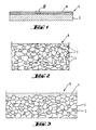
In der Figur 1 ist der Schichtwerkstoff 1 im Schnitt dargestellt, der aus einem
Trägerwerkstoff 2 besteht, auf dem der Lagerwerkstoff als Gleitschicht 6
aufgesputtert ist. Es handelt sich hierbei um eine Kupfer-Blei-Legierung, die in
der Figur 2 vergrößert dargestellt ist. Das Matrixmaterial 4, das in dem hier
gezeigten Beispiel aus Kupfer besteht, ist isotrop mit polygonaler Korngestalt
kristallisiert, d.h. es gibt keine Vorzugsrichtung oder gar ein Stengelwachstum.
An den Korngrenzen sind Bleiteilchen 3 eingelagert, deren Korngrößen im
Bereich des 0,2 - 0,4 µm-fachen der Matrixkristalle liegen.In FIG. 1, the
Der in den Figuren 1 und 2 dargestellte Schichtwerkstoff wurde wie folgt hergestellt:The layer material shown in FIGS. 1 and 2 was as follows manufactured:
Lagerschalen des Aufbaues Stahl/CuPb22Sn werden auf einem Träger in einer konventionellen Kathodenzerstäubungsanlage gegenüber einem Target, das die Zusammensetzung der resultierenden Gleitschicht (z.B. CuPb30Sn) hat, plaziert. Nach dem Evakuieren der Sputteranlage bis auf etwa 10-4 mbar und dem Fluten des Rezipienten mit Argon wird durch Umkehrung des normalen Sputterprozesses die Oberfläche der Lagerschalen freigesputtert.Bearing cups made of steel / CuPb22Sn are built on a carrier in a conventional cathode sputtering system against a target that the Composition of the resulting sliding layer (e.g. CuPb30Sn), placed. After evacuating the sputtering system to about 10-4 mbar and the recipient is flooded with argon by reversing the normal Sputtering process sputtered the surface of the bearing shells.
Bei einem Druck von etwa 3,5 x 10⁻² mbar und einer in das Target eingebrachten Leistungsdichte 13 W/cm2 konnte anschließend eine Schicht der Zusammensetzung CuPb28Sn abgeschieden werden. Für den angestrebten Gefügeaufbau der Sputterschicht haben sich hierbei Beschichtungstemperaturen von > 175°C als Optimum herauskristallisiert. Die mit diesen Eckwerten erreichte Abscheidungsrate für das System CuPbSn liegt (je nach in das Traget eingebrachter Leistung) zwischen 0,45 und 0,5 µm/min.At a pressure of about 3.5 x 10⁻² mbar and a power density of 13 W / cm 2 introduced into the target, a layer of the composition CuPb28Sn could then be deposited. Coating temperatures of> 175 ° C have emerged as the optimum for the desired structure of the sputter layer. The deposition rate achieved with these basic parameters for the system is CuPbSn (depending is mounted in the Traget power) from 0.45 to 0.5 μ m / min.
So hergestellte Gleitschichten haben eine Härte von 170-190 HV.Sliding layers produced in this way have a hardness of 170-190 HV.
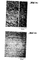
In der Figur 3 ist ein Schnitt durch die in Figur 2 gezeigte Sputterschicht 6
nach der Einlaufphase dargestellt. Unter Einlaufphase wird die Phase
verstanden, bis sich Gleitlager und Gegenläufer in ihrer Oberflächenstruktur
aneinander angepaßt haben. Aufgrund der Wärmeentwicklung wandert das Blei
über die Korngrenzen des Matrixwerkstoffes 4 an die Oberfläche und bildet
dort eine weiche Deckschicht 5, die 1 - 3 µm dick ist.FIG. 3 shows a section through the
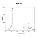
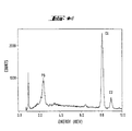
Figur 4a zeigt eine Oberflächenaufnahme einer gelaufenen Lagerschale. Deutlich erkennbar ist das gute Anpassungsverhalten der Sputterschicht, was sich in der Riefenausbildung, verursacht durch Schmutzpartikel im Öl wiederspiegelt.Figure 4a shows a surface image of a running bearing shell. The good adaptation behavior of the sputter layer is clearly recognizable, what groove formation, caused by dirt particles in the oil reflects.
Figur 4b zeigt ebenfalls eine Oberflächenaufnahme der gleichen Lagerschale jedoch nach Entfernen der Pb-reichen Deckschicht. Die dazugehörigen Röntgenspektren belegen den hohen Pb-Gehalt der Deckschicht (Figur 4c), der sich während der Einlaufpahse ausbildet und verantwortlich ist für das erwähnte gute Anpassungsvermögen der Laufschicht. Nach Entfernen der Pb-reichen Schicht ist in Figur 4d die Zusammensetzung der darunterliegenden Bereiche dargestellt. Figure 4b also shows a surface image of the same bearing shell however after removing the Pb-rich top layer. The related ones X-ray spectra demonstrate the high Pb content of the top layer (FIG. 4c), the forms during the intake phase and is responsible for that mentioned good adaptability of the running layer. After removing the Pb-rich The layer in FIG. 4d is the composition of the layer below Areas shown.
- 11
- SchichtwerkstoffLayer material
- 22nd
- TrägerwerkstoffCarrier material
- 33rd
- BleiteilchenLead particles
- 44th
- MatrixwerkstoffMatrix material
- 55
- DeckschichtTop layer
- 66
- GleitschichtSliding layer
Claims (14)
- A laminate material comprising a bearing material which is applied directly to a carrier material by means of sputtering and which has a matrix material of copper or copper-based alloy with finely distributed lead inclusions, characterised in that
the matrix material (4) is isotropically crystallised with a polygonal grain shape, wherein the mean crystallite diameter is 2 - 4 µm and the grain size of the lead inclusions (3) is 0.2 - 0.4 times the crystallite diameter. - A laminate material according to claim 1 characterised in that the lead inclusions (3) are of a mean grain diameter of between 0.4 µm and 1.6 µm.
- A laminate material according to claim 1 or claim 2 characterised in that the proportion of lead is from 15 to 45 % by weight.
- A laminate material according to claim 3 characterised in that the proportion of lead is from 30 to 45 % by weight.
- A laminate material according to one of claims 1 to 4 characterised in that the matrix material (4) contains the following additions individually or in combination: tin, nickel, aluminium and zinc.
- A laminate material according to claim 5 characterised in that the additions are contained in the matrix material (4) in the following proportions: lead from 0 to 10 % by weight, nickel from 2 to 8 % by weight, zinc from 5 to 25 % by weight and aluminium from 2 to 10 % by weight.
- A laminate material according to one of claims 1 to 6 characterised in that the bearing material is provided with a ternary layer applied by electroplating or with a flash.
- A laminate material according to claim 7 characterised in that the thickness of the ternary layer is from 3 to 8 µm and the thickness of the flash is from 1 to 3 µm.
- A laminate material according to one of claims 7 and 8 characterised in that the thickness of the bearing material is from 10 to 13 µm.
- A laminate material according to one of claims 1 to 9 characterised in that the total thickness of the running layer comprising bearing material and ternary layer or flash is from 16 to 18 µm.
- A laminate material according to one of claims 1 to 10 characterised in that the carrier material contains copper.
- A laminate material according to claim 11 characterised in that the carrier material is a copper-lead-tin alloy.
- A laminate material according to one of claims 11 and 12 characterised in that the copper-lead-tin alloy is plated onto a steel backing metal by a casting procedure.
- A laminate material according to one of claims 1 to 10 characterised in that the carrier material is a steel backing metal.
Applications Claiming Priority (3)
| Application Number | Priority Date | Filing Date | Title |
|---|---|---|---|
| DE19525330 | 1995-07-12 | ||
| DE19525330A DE19525330C2 (en) | 1995-07-12 | 1995-07-12 | Layer material |
| PCT/DE1996/001272 WO1997003219A1 (en) | 1995-07-12 | 1996-07-10 | Laminated material |
Publications (2)
| Publication Number | Publication Date |
|---|---|
| EP0837953A1 EP0837953A1 (en) | 1998-04-29 |
| EP0837953B1 true EP0837953B1 (en) | 2001-10-24 |
Family
ID=7766603
Family Applications (1)
| Application Number | Title | Priority Date | Filing Date |
|---|---|---|---|
| EP96923838A Expired - Lifetime EP0837953B1 (en) | 1995-07-12 | 1996-07-10 | Laminated material |
Country Status (9)
| Country | Link |
|---|---|
| US (1) | US6143427A (en) |
| EP (1) | EP0837953B1 (en) |
| JP (1) | JP2000513765A (en) |
| KR (1) | KR100413721B1 (en) |
| AT (1) | ATE207551T1 (en) |
| BR (1) | BR9609597A (en) |
| DE (2) | DE19525330C2 (en) |
| ES (1) | ES2165988T3 (en) |
| WO (1) | WO1997003219A1 (en) |
Families Citing this family (13)
| Publication number | Priority date | Publication date | Assignee | Title |
|---|---|---|---|---|
| JP2002060870A (en) * | 2000-08-24 | 2002-02-28 | Taiho Kogyo Co Ltd | Cu-Pb BASED COPPER ALLOY HAVING FINE LEAD STRUCTURE AND PLAIN BEARING FOR INTERNAL COMBUSTION ENGINE |
| US9896745B2 (en) * | 2002-01-30 | 2018-02-20 | Jx Nippon Mining & Metals Corporation | Copper alloy sputtering target and method for manufacturing the target |
| JP4794802B2 (en) | 2002-11-21 | 2011-10-19 | Jx日鉱日石金属株式会社 | Copper alloy sputtering target and semiconductor device wiring |
| JP4223511B2 (en) * | 2003-03-17 | 2009-02-12 | 日鉱金属株式会社 | Copper alloy sputtering target, method of manufacturing the same, and semiconductor element wiring |
| DE102005063324B4 (en) | 2005-05-13 | 2008-02-28 | Federal-Mogul Wiesbaden Gmbh & Co. Kg | Slide bearing composite, use and manufacturing process |
| DE102005063325B4 (en) * | 2005-05-13 | 2008-01-10 | Federal-Mogul Wiesbaden Gmbh & Co. Kg | Slide bearing composite, use and manufacturing process |
| DE102005023307B4 (en) * | 2005-05-13 | 2009-05-07 | Federal-Mogul Wiesbaden Gmbh | Slide bearing composite, use and manufacturing process |
| DE102005023308B4 (en) * | 2005-05-13 | 2007-02-08 | Federal-Mogul Wiesbaden Gmbh & Co. Kg | Slide bearing composite, use and manufacturing process |
| DE102005023309B4 (en) | 2005-05-13 | 2009-10-01 | Federal-Mogul Wiesbaden Gmbh | Slide bearing composite, use and manufacturing process |
| DE102005023306B4 (en) * | 2005-05-13 | 2007-04-05 | Federal-Mogul Wiesbaden Gmbh & Co. Kg | Slide bearing composite, use and manufacturing process |
| JP4732941B2 (en) * | 2006-03-30 | 2011-07-27 | 大同メタル工業株式会社 | Sliding material and method for producing the same |
| JP2012062941A (en) * | 2010-09-15 | 2012-03-29 | Daido Metal Co Ltd | Sliding member |
| JP7249105B2 (en) * | 2018-03-22 | 2023-03-30 | 大同メタル工業株式会社 | sliding member |
Family Cites Families (14)
| Publication number | Priority date | Publication date | Assignee | Title |
|---|---|---|---|---|
| DE2853724C3 (en) * | 1978-12-13 | 1981-07-16 | Glyco-Metall-Werke Daelen & Loos Gmbh, 6200 Wiesbaden | Layered material or layered workpiece and process for its production |
| CH671239A5 (en) * | 1986-07-15 | 1989-08-15 | Balzers Hochvakuum | |
| DE3640767A1 (en) * | 1986-10-30 | 1988-05-05 | Kolbenschmidt Ag | STORAGE |
| US4961831A (en) * | 1986-12-23 | 1990-10-09 | Balzers Aktiengesellschaft | Composite material having a slide layer applied by cathode sputtering |
| ATE79589T1 (en) * | 1987-04-30 | 1992-09-15 | Balzers Hochvakuum | COMPONENT, ESPECIALLY MACHINE ELEMENT. |
| DE8717379U1 (en) * | 1987-06-25 | 1988-10-20 | Glyco-Metall-Werke Daelen & Loos Gmbh, 6200 Wiesbaden, De | |
| AT389356B (en) * | 1987-07-24 | 1989-11-27 | Miba Gleitlager Ag | HEAVY DUTY SLIDING BEARING |
| US5093207A (en) * | 1988-04-23 | 1992-03-03 | Glyco Aktiengesellschaft | Laminate material or laminate workpiece with a functional layer, especially a friction bearing layer, disposed on a backing layer |
| DE3813804A1 (en) * | 1988-04-23 | 1989-11-09 | Glyco Metall Werke | LAYERING MATERIAL OR LAYERING MATERIAL AND METHOD FOR THE PRODUCTION THEREOF |
| GB8915254D0 (en) * | 1989-07-03 | 1989-08-23 | T & N Technology Ltd | Bearings |
| US5004581A (en) * | 1989-07-31 | 1991-04-02 | Toyota Jidosha Kabushiki Kaisha | Dispersion strengthened copper-base alloy for overlay |
| JPH0771744B2 (en) * | 1990-12-27 | 1995-08-02 | 大同メタル工業株式会社 | Composite sliding material and manufacturing method thereof |
| US5282908A (en) * | 1992-11-03 | 1994-02-01 | Chuetsu Metal Works Co., Ltd. | High strength α brass containing Mn, Si, Co, Fe, Sn and Pb |
| US5685797A (en) * | 1995-05-17 | 1997-11-11 | United Technologies Corporation | Coated planet gear journal bearing and process of making same |
-
1995
- 1995-07-12 DE DE19525330A patent/DE19525330C2/en not_active Expired - Fee Related
-
1996
- 1996-07-10 US US08/981,614 patent/US6143427A/en not_active Expired - Fee Related
- 1996-07-10 KR KR10-1998-0700148A patent/KR100413721B1/en not_active IP Right Cessation
- 1996-07-10 ES ES96923838T patent/ES2165988T3/en not_active Expired - Lifetime
- 1996-07-10 DE DE59608019T patent/DE59608019D1/en not_active Expired - Fee Related
- 1996-07-10 AT AT96923838T patent/ATE207551T1/en not_active IP Right Cessation
- 1996-07-10 JP JP09505415A patent/JP2000513765A/en active Pending
- 1996-07-10 WO PCT/DE1996/001272 patent/WO1997003219A1/en active IP Right Grant
- 1996-07-10 EP EP96923838A patent/EP0837953B1/en not_active Expired - Lifetime
- 1996-07-10 BR BR9609597A patent/BR9609597A/en not_active IP Right Cessation
Also Published As
| Publication number | Publication date |
|---|---|
| KR19990028847A (en) | 1999-04-15 |
| US6143427A (en) | 2000-11-07 |
| DE19525330C2 (en) | 1998-07-09 |
| JP2000513765A (en) | 2000-10-17 |
| KR100413721B1 (en) | 2004-03-24 |
| WO1997003219A1 (en) | 1997-01-30 |
| EP0837953A1 (en) | 1998-04-29 |
| ES2165988T3 (en) | 2002-04-01 |
| BR9609597A (en) | 1999-02-23 |
| ATE207551T1 (en) | 2001-11-15 |
| DE19525330A1 (en) | 1997-01-16 |
| DE59608019D1 (en) | 2001-11-29 |
Similar Documents
| Publication | Publication Date | Title |
|---|---|---|
| AT411229B (en) | LAYER COMPOSITE MATERIAL FOR SLIDING ELEMENTS AND METHOD FOR THE PRODUCTION THEREOF | |
| AT407532B (en) | COMPOSITE OF AT LEAST TWO LAYERS | |
| EP2902526B1 (en) | Multi-layer sliding bearing | |
| DE19981425B4 (en) | Sliding bearing with an intermediate layer, in particular bonding layer, of an aluminum-based alloy | |
| DE102006019826B3 (en) | Strip-like composite material for composite sliding elements or connectors comprises a layer made from a copper multiple material alloy with a protective layer of deep-drawing steel, tempering steel or case hardening steel | |
| AT511196B1 (en) | COMPOSITE BEARING | |
| DE3631029C2 (en) | Tin-containing aluminum bearing alloy and use of the same for a two-layer bearing material | |
| EP0837953B1 (en) | Laminated material | |
| EP2209621B1 (en) | Method for producing a sliding bearing element having a bismuth-containing sliding layer, and sliding bearing element | |
| EP3374533B1 (en) | High tensile brass alloy and high tensile brass alloy product | |
| DE3249133C2 (en) | Process for producing an aluminium-based alloy for bearings and use of said alloy | |
| DE10062876C1 (en) | Connecting rod bearing shell for connecting rod of titanium or titanium alloy has supporting layer of steel material, and on back of support layer has coating of tin-bronze material with thickness of 10-50 micrometers | |
| DE69917867T2 (en) | bearings | |
| DE4413954A1 (en) | Bearing material based on a copper-lead alloy with excellent corrosion resistance and process for producing the same | |
| WO2017127858A1 (en) | Method for producing a sliding bearing element | |
| EP3825119A1 (en) | Multilayer sliding bearing element | |
| EP3087282B1 (en) | Multi-layer sliding bearing | |
| WO2009049725A2 (en) | Plain bearing comprising a sliding and a running-in layer and method for producing the same | |
| EP2928685B1 (en) | Sliding bearing composite material | |
| WO1998017833A2 (en) | Sliding bearing material made from an aluminium alloy which is silicon-free apart from impurities necessitated by steel production | |
| DE102007049042A1 (en) | Slide bearing with sliding layer and inlet layer |
Legal Events
| Date | Code | Title | Description |
|---|---|---|---|
| PUAI | Public reference made under article 153(3) epc to a published international application that has entered the european phase |
Free format text: ORIGINAL CODE: 0009012 |
|
| 17P | Request for examination filed |
Effective date: 19980108 |
|
| AK | Designated contracting states |
Kind code of ref document: A1 Designated state(s): AT DE ES FR GB IT |
|
| RAP1 | Party data changed (applicant data changed or rights of an application transferred) |
Owner name: FEDERAL-MOGUL WIESBADEN GMBH |
|
| GRAG | Despatch of communication of intention to grant |
Free format text: ORIGINAL CODE: EPIDOS AGRA |
|
| 17Q | First examination report despatched |
Effective date: 20000512 |
|
| GRAG | Despatch of communication of intention to grant |
Free format text: ORIGINAL CODE: EPIDOS AGRA |
|
| GRAH | Despatch of communication of intention to grant a patent |
Free format text: ORIGINAL CODE: EPIDOS IGRA |
|
| GRAH | Despatch of communication of intention to grant a patent |
Free format text: ORIGINAL CODE: EPIDOS IGRA |
|
| RAP1 | Party data changed (applicant data changed or rights of an application transferred) |
Owner name: FEDERAL-MOGUL WIESBADEN GMBH & CO.KG |
|
| GRAA | (expected) grant |
Free format text: ORIGINAL CODE: 0009210 |
|
| AK | Designated contracting states |
Kind code of ref document: B1 Designated state(s): AT DE ES FR GB IT |
|
| REF | Corresponds to: |
Ref document number: 207551 Country of ref document: AT Date of ref document: 20011115 Kind code of ref document: T |
|
| REF | Corresponds to: |
Ref document number: 59608019 Country of ref document: DE Date of ref document: 20011129 |
|
| REG | Reference to a national code |
Ref country code: GB Ref legal event code: IF02 |
|
| GBT | Gb: translation of ep patent filed (gb section 77(6)(a)/1977) |
Effective date: 20020106 |
|
| ET | Fr: translation filed | ||
| REG | Reference to a national code |
Ref country code: ES Ref legal event code: FG2A Ref document number: 2165988 Country of ref document: ES Kind code of ref document: T3 |
|
| PLBE | No opposition filed within time limit |
Free format text: ORIGINAL CODE: 0009261 |
|
| STAA | Information on the status of an ep patent application or granted ep patent |
Free format text: STATUS: NO OPPOSITION FILED WITHIN TIME LIMIT |
|
| 26N | No opposition filed | ||
| PGFP | Annual fee paid to national office [announced via postgrant information from national office to epo] |
Ref country code: GB Payment date: 20050614 Year of fee payment: 10 Ref country code: AT Payment date: 20050614 Year of fee payment: 10 |
|
| PGFP | Annual fee paid to national office [announced via postgrant information from national office to epo] |
Ref country code: FR Payment date: 20050706 Year of fee payment: 10 |
|
| PGFP | Annual fee paid to national office [announced via postgrant information from national office to epo] |
Ref country code: ES Payment date: 20050712 Year of fee payment: 10 |
|
| PGFP | Annual fee paid to national office [announced via postgrant information from national office to epo] |
Ref country code: DE Payment date: 20050729 Year of fee payment: 10 |
|
| PG25 | Lapsed in a contracting state [announced via postgrant information from national office to epo] |
Ref country code: GB Free format text: LAPSE BECAUSE OF NON-PAYMENT OF DUE FEES Effective date: 20060710 Ref country code: AT Free format text: LAPSE BECAUSE OF NON-PAYMENT OF DUE FEES Effective date: 20060710 |
|
| PGFP | Annual fee paid to national office [announced via postgrant information from national office to epo] |
Ref country code: IT Payment date: 20060731 Year of fee payment: 11 |
|
| PG25 | Lapsed in a contracting state [announced via postgrant information from national office to epo] |
Ref country code: DE Free format text: LAPSE BECAUSE OF NON-PAYMENT OF DUE FEES Effective date: 20070201 |
|
| GBPC | Gb: european patent ceased through non-payment of renewal fee |
Effective date: 20060710 |
|
| REG | Reference to a national code |
Ref country code: FR Ref legal event code: ST Effective date: 20070330 |
|
| REG | Reference to a national code |
Ref country code: ES Ref legal event code: FD2A Effective date: 20060711 |
|
| PG25 | Lapsed in a contracting state [announced via postgrant information from national office to epo] |
Ref country code: ES Free format text: LAPSE BECAUSE OF NON-PAYMENT OF DUE FEES Effective date: 20060711 |
|
| PG25 | Lapsed in a contracting state [announced via postgrant information from national office to epo] |
Ref country code: FR Free format text: LAPSE BECAUSE OF NON-PAYMENT OF DUE FEES Effective date: 20060731 |
|
| PG25 | Lapsed in a contracting state [announced via postgrant information from national office to epo] |
Ref country code: IT Free format text: LAPSE BECAUSE OF NON-PAYMENT OF DUE FEES Effective date: 20070710 |