EP0837487B1 - Focusing electrode in electron gun for color cathode ray tube - Google Patents
Focusing electrode in electron gun for color cathode ray tube Download PDFInfo
- Publication number
- EP0837487B1 EP0837487B1 EP97302287A EP97302287A EP0837487B1 EP 0837487 B1 EP0837487 B1 EP 0837487B1 EP 97302287 A EP97302287 A EP 97302287A EP 97302287 A EP97302287 A EP 97302287A EP 0837487 B1 EP0837487 B1 EP 0837487B1
- Authority
- EP
- European Patent Office
- Prior art keywords
- focusing electrode
- electron beam
- holes
- beam pass
- focusing
- Prior art date
- Legal status (The legal status is an assumption and is not a legal conclusion. Google has not performed a legal analysis and makes no representation as to the accuracy of the status listed.)
- Expired - Lifetime
Links
- 238000010894 electron beam technology Methods 0.000 claims description 88
- 201000009310 astigmatism Diseases 0.000 description 9
- 238000012937 correction Methods 0.000 description 5
- 238000013461 design Methods 0.000 description 4
- 239000011324 bead Substances 0.000 description 3
- 230000004927 fusion Effects 0.000 description 3
- 239000011521 glass Substances 0.000 description 3
- 239000000463 material Substances 0.000 description 3
- 230000015572 biosynthetic process Effects 0.000 description 2
- 238000004519 manufacturing process Methods 0.000 description 2
- 238000012986 modification Methods 0.000 description 2
- 230000004048 modification Effects 0.000 description 2
- 238000005094 computer simulation Methods 0.000 description 1
- 239000006185 dispersion Substances 0.000 description 1
- 238000010438 heat treatment Methods 0.000 description 1
- 238000003780 insertion Methods 0.000 description 1
- 230000037431 insertion Effects 0.000 description 1
- 238000005259 measurement Methods 0.000 description 1
- 230000002265 prevention Effects 0.000 description 1
- 238000004904 shortening Methods 0.000 description 1
- 238000004088 simulation Methods 0.000 description 1
- 230000003068 static effect Effects 0.000 description 1
- 230000001360 synchronised effect Effects 0.000 description 1
- 230000003313 weakening effect Effects 0.000 description 1
- 238000003466 welding Methods 0.000 description 1
Images


Classifications
-
- H—ELECTRICITY
- H01—ELECTRIC ELEMENTS
- H01J—ELECTRIC DISCHARGE TUBES OR DISCHARGE LAMPS
- H01J29/00—Details of cathode-ray tubes or of electron-beam tubes of the types covered by group H01J31/00
- H01J29/46—Arrangements of electrodes and associated parts for generating or controlling the ray or beam, e.g. electron-optical arrangement
- H01J29/48—Electron guns
- H01J29/50—Electron guns two or more guns in a single vacuum space, e.g. for plural-ray tube
- H01J29/503—Three or more guns, the axes of which lay in a common plane
-
- H—ELECTRICITY
- H01—ELECTRIC ELEMENTS
- H01J—ELECTRIC DISCHARGE TUBES OR DISCHARGE LAMPS
- H01J29/00—Details of cathode-ray tubes or of electron-beam tubes of the types covered by group H01J31/00
- H01J29/46—Arrangements of electrodes and associated parts for generating or controlling the ray or beam, e.g. electron-optical arrangement
- H01J29/58—Arrangements for focusing or reflecting ray or beam
- H01J29/62—Electrostatic lenses
- H01J29/626—Electrostatic lenses producing fields exhibiting periodic axial symmetry, e.g. multipolar fields
- H01J29/628—Electrostatic lenses producing fields exhibiting periodic axial symmetry, e.g. multipolar fields co-operating with or closely associated to an electron gun
Definitions
- the present invention relates to an electron gun for a color TV or industrial high definition cathode ray tube, and more particularly, to a focusing electrode assembly in an electron gun for a color cathode ray tube, which can provide a higher freedom in an electron gun design and reduce an error occurred during assembly of the electron gun.
- the electron gun in a color cathode ray tube focuses three electron beams emitted from cathodes onto a surface of red, green and blue fluorescent materials coated inside of a cathode ray tube so that each of the fluorescent materials react to the electron beams to luminesce, to form a pixel on a screen.
- Fig. 1 illustrates a sectional view of a general color cathode ray tube.
- the color cathode ray tube 104 includes an in-line type electron gun 102, deflection yokes 103 for deflecting electron beams 101 in up and down and left and right directions all over the screen, and a screen 105 for forming pixels in reaction to the electron beams.
- the screen includes a fluorescent surface 106 having an inside surface coated with fluorescent materials, a funnel 107 converged from the rim of the screen toward rear of the screen, and a neck part 108 formed at an end of the funnel.
- the in-line electron gun is mounted inside of the neck part and the deflection yokes are mounted outside of the neck part.
- a shadow mask 109 having a plurality of electron beam pass through holes 191 for allowing selective collision of the electron beams shot from the in-line type electron gun onto the fluorescent surface, is provided between the fluorescent surface and the electron gun.
- Fig. 2 illustrates a cross sectional view of the in-line type electron gun shown in Fig. 1
- Fig. 3A illustrates examples of distortion of electron beam spots on a screen caused by a non-uniform magnetic field formed by deflection yokes
- Fig. 3B illustrates examples of correction of the electron beam spots shown in Fig. 3B by a dynamic quadrupole lens formed by a focusing electrode having burring parts.
- the in-line type electron gun 102 at large includes a tripolar parts 21 and a main focal electrostatic lens part 22.
- the tripolar part 21 includes, in the order from the neck part 8 toward the screen 5, cathodes 23 for emitting thermal electrons following heating of heaters 231 provided therein, a controlling electrode 24 for controlling the thermal electrons, and an accelerating electrode 25 for accelerating the thermal electrons.
- the main focal electrostatic lens part 22 disposed next to the tripolar part 21 includes a focusing lens 26 and an anode 27 arranged in this order.
- Predetermined voltages different from one another are applied to the electrodes; in general, the controlling electrode 24 is grounded, the accelerating electrode 25 is applied of a low voltage of 500 ⁇ 1000 V, the anode 27 is applied of a high voltage of 25 ⁇ 35 Kv, and the focusing electrode 26 is applied of an intermediate voltage, a voltage corresponding to 20 ⁇ 30 % of the voltage applied to the anode 27.
- a voltage difference formed by, and between the focusing lens 26 and the anode 27 forms equipotential planes, which, collectively, act as the main focal electrostatic lens. Accordingly, the electron beams, accelerated by the voltage difference of the anode 27 toward the screen, are focused by the main focal electrostatic lens, pass through the electron beam pass-through hole in the shadow mask, and collide on the fluorescent surface on the central part of the screen, to form a pixel.
- the deflection of the electron beams by the deflection yokes is required for the sequential scanning of the electron beams onto each region of the screen.
- the mismatch of the convergence can be corrected by providing a self convergence of the beams using deflection yokes which can form a non-uniform magnetic field.
- the application of the non-uniform magnetic filed causes a problem in which the electron beam forms a spot of horizontally elongated form with a haze, which is a thin dispersion of an image, on the upper and lower sides of the spot.
- the electron beam forms a distorted spot on the screen as shown in Fig. 3A.
- a dynamic quadrupole lens which is operative synchronous to a deflection synchronizing signal has been used for correction of an astigmatism when the electron beam is deflected toward periphery of the screen.
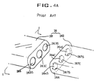
- Fig. 4A illustrates a perspective view of a two divisional focusing electrode disassembly for a conventional in-line type electron gun, which can form the dynamic quadrupole lens.
- the focusing electrode 26 includes a first focusing electrode 261 for being applied of a constant voltage, a second focusing electrode 262 arranged next to the first focusing lens for being applied of a dynamic voltage to make a voltage difference of about 300 V ⁇ 1000 V depending on extent of deflection of the electron beam, oppositely faced surfaces 265 and 266 of the first and second focusing electrodes 261 and 262 at one ends thereof each having first and second electron beam pass-through holes(263c, 263s and 264c, 264s), and a pair of burring parts 267c and 267s at upper and lower portions of the circumference of each of the electron beam pass-through holes 264c and 264s in the second focusing electrode.
- each of the burring parts 267c and 267s are inserted in the electron beam pass-through holes 263c and 263s in the first focusing electrode.
- a dynamic quadrupole lens is formed by the voltage difference between the first focusing electrode 261 to which a low static voltage is applied and the second focusing electrode 262 to which a high dynamic voltage is applied.
- the diverging power acts stronger than the converging power from the first focusing electrode 261 which converges the electron beam to correct the electron beam into a vertically elongated form. Accordingly, the horizontally elongated form of astigmatism of the electron beam caused by the deflection yokes can be corrected as shown in Fig. 3B.
- the voltage difference of about 300 V ⁇ 1000 V between the voltages applied to the first and second focusing electrodes 261 and 262 might give damages to parts of the electron gun in case of occurrence of discharge between them, which causes a problem of shortening a life time of the cathode ray tube.
- the voltage difference of about 300 V ⁇ 1000 V between the voltages applied to the first and second focusing electrodes 261 and 262 might give damages to parts of the electron gun in case of occurrence of discharge between them, which causes a problem of shortening a life time of the cathode ray tube.
- the in-line type electron gun under production currently has been designed to have a pitch S, which is a distance between adjacent axes of the electron beam pass-through holes 263c, 263s and 264c, 264s, of 5.5 mm, a diameter D2 of each of the electron beam pass-through holes 264c and 264s in the second focusing electrode of 4.0 mm, a thickness t of each of the parts of the electron gun of 0.33 mm, a bridge width, which is a distance between adjacent electron beam pass-through holes 263c and 263s in the first focusing electrode of b mm, and a gap between the electron beam pass-through holes 263c and 263s in the first focusing electrode and the burring parts 267 limited to a > 2 mm which does not cause discharge.
- a pitch S which is a distance between adjacent axes of the electron beam pass-through holes 263c, 263s and 264c, 264s, of 5.5 mm
- the mandrel has an outside diameter tightly fit to the inside diameter of the second focusing electrodes 264c and 264s, the electron beam pass-through holes 263c and 263s in the first focusing electrode, which is, as has been explained, greater than the electron beam pass-through holes 264c and 264s in the second focusing electrode could not be fixed to the mandrel firmly, to result movement of the first focusing electrode 261 during the bead glass fusion welding, which causes misassembly of the first focusing electrode 261 that causes a problem that the electron gun can not provide a designed performance.
- the magnetic field from the dynamic quadrupole lens weakens a focusing power ofthe main focal electrostatic lens to the outer electron beams, which deteriorates the resolution.
- German patent publication DE 4215127 A1 discloses a focusing assembly for an electron gun in which upper and lower burring parts provided adjacent to electron beam pass-through holes in a second electrode are located within vertically elongated electron beam pass-through holes in a first electrode which are provided with vertically aligned burring parts adjacent thereto.
- United Kingdom patent specification 1514235 discloses a focusing assembly for an electron gun in which burring parts are formed on the upper and lower edges of electron beam pass-through holes.
- German patent publication DE 3839389 A1 discloses a focusing assembly for an electron gun in which a plate of a first electrode bearing electron beam pass-through holes is disposed inwardly from an open face of the first electrode through which lateral plates of a second electrode extend.
- the invention provides a focusing electrode assembly as set out in claim 1.
- Preferred embodiments of the invention seek to provide a focusing electrode assembly in an electron gun for a color cathode ray tube that substantially obviates one or more of the problems due to limitations and disadvantages of the related art.
- a focusing electrode assembly in an electron gun for a color cathode ray tube which allows insertion of the upper and lower burring parts into each of the electron beam pass-through holes in the first focusing electrode without the reduction of the bridge.
- Embodiments provide a focusing electrode assembly in an electron gun for a color cathode ray tube, of which first focusing electrode also can be fixed by the mandrels that fix the second focusing electrode.
- a focusing electrode assembly in an electron gun for a color cathode ray tube which can prevent the weakening of the focusing power of the main focal electrostatic lens to the outer electron beams caused by the dynamic quadrupole lens formed between the first and second electrodes.
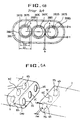
- Fig. 5A illustrates a perspective view of a disassembly of a focusing electrode in accordance with a preferred embodiment of the present invention
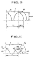
- Fig. 5B illustrates a front view of a part of a first focusing electrode shown in Fig. 5A
- Fig. 5C illustrates a front view of a part of a second focusing electrode shown in Fig. 5A.
- the focusing electrode in an electron gun for a color cathode ray tube in accordance with a preferred embodiment of the present invention includes a first focusing electrode 1 having electron beam pass-through holes 3c and 3s for being applied of a constant voltage, a second focusing electrode 2 having electron beam pass-through holes 4c and 4s each with upper and lower burring parts 7c and 7s for being applied of a dynamic voltage according to an extent of deflection of the electron beam by deflection yokes.
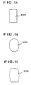
- each of the electron beam pass-through holes 3c and 3s in the first focusing electrode is formed in a vertically elongated form so as to accept the burring parts 7c and 7s. That is, as shown in Fig. 5B, each of the electron beam pass-through holes 3c and 3s is formed in a vertically elongated form which has a vertical radius Rv greater than a horizontal radius Rs, preferably to a size enough to prevent occurrence of discharge between the burring parts 7c and 7s and the electron beam pass-through holes 3c and 3s in the first focusing electrode. As shown in Figs. 6A, 6B and 6C, the vertically elongated form of each of the electron beam pass-through holes 3c and 3s may be a polygon with straight sides, oval with curved sides, or a form with straight sides and curved sides.
- the focusing electrode is provided with an internal electrode arranged inside of the first focusing electrode 1 having electron beam pass-through holes 5C and 6s each disposed on the same axis with the axis, and having the same diameter with the diameter of the electron beam pass-through holes 4c and 4s in the second focusing electrode 2 for fixing the first focusing electrode 1 as well as the second focusing electrode with the same mandrels.
- a distance S from the center electron beam pass-through hole 3c to each of the side electron beam pass-through holes 3s in the first focusing electrode is preferably formed smaller than a distance S' from the center electron beam pass-through hole 4c to each of the side electron beam pass-through holes 4s in the second focusing electrode, to correct the drop of the focusing power of the main focal electrostatic lens to the side beams.
- design parameters for each of the parts of the focusing electrode are obtainable by means of computer three dimensional simulations, of which steps will be explained.
- focus voltages at the center, top, each edge and each corner of the screen is measured.
- focus voltages at the center, top, each edge and each corner of the screen is measured.
- focus voltages at the center, top, each edge and each corner of the screen is measured.
- the focus voltages it can be known that there are almost no variation of the focus voltage according to the variation of position in a horizontal direction, and there are exponential variation according to the variation of position in a vertical direction. Accordingly, astigmatisms in the horizontal direction are excluded, and the values obtained by subtracting a center focus voltage value from the focus voltage values at each position are those astigmatism components which should be finally improved.
- the astigmatism component can be classified into components from a focal distance, a diverging angle and a radius of the electron beam.
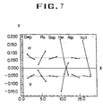
- Fig. 7 illustrates a graph showing extents of deflections of an electron beam depending on dimensions of parts in the focusing electrode embodying the present invention.
- one increment on the X-axis represents a dimensional change by 0.1 mm of the parts in the electrode
- one increment on the Y-axis represents a change in the focal distance of which upper side of X-axis represents focusing characteristics of the electron beam in a horizontal direction and lower side of X-axis represents focusing characteristics of the electron beam in a vertical direction, of which results are shown in TABLE 1 shown below.
- the focusing power is particularly sensitive to changes of the height of the burring parts 7c and 7s and an X-axis change of the horizontal diameter Rs of the electron beam pass-through holes 3c and 3s in the first focusing electrode; the smaller the horizontal diameter, the stronger the power of the quadrupole lens. This is the reason why the distance S from the center electron beam pass-through hole 3c to each of the side electron beam pass-through holes 3s in the first focusing electrode is formed smaller than the distance S' from the center electron beam pass-through hole 4c to each of the side electron beam pass-through holes 4s in the second focusing electrode, for correcting the drop of the focusing power of the main focal electrostatic lens to the side beams.
- the focal distance can be simply changed only with the change of the depth of the internal electrode without any particular change in the horizontal radius Rs or the height Hei of the burring part.
- each of the electron beam pass-through holes elongated only in upper and lower portions into an elongated form permits to reinforce the bridge.
- the provision of the internal electrode in the first focusing electrode having electron beam pass-through holes, each of which can be tightly fitted on a mandrel, can prevent shaking of the first focusing during beading of the electron gun, thereby fabrication of a precise electron gun is facilitated.
- a capacity change of an electron gun can be tolerated to a certain extent only limited to the focusing electrode without any change of the design even if particulars of the electron gun are changed depending on a size of a cathode ray tube.
Landscapes
- Cathode-Ray Tubes And Fluorescent Screens For Display (AREA)
- Video Image Reproduction Devices For Color Tv Systems (AREA)
- Electrodes For Cathode-Ray Tubes (AREA)
Description
- The present invention relates to an electron gun for a color TV or industrial high definition cathode ray tube, and more particularly, to a focusing electrode assembly in an electron gun for a color cathode ray tube, which can provide a higher freedom in an electron gun design and reduce an error occurred during assembly of the electron gun.
- The electron gun in a color cathode ray tube focuses three electron beams emitted from cathodes onto a surface of red, green and blue fluorescent materials coated inside of a cathode ray tube so that each of the fluorescent materials react to the electron beams to luminesce, to form a pixel on a screen.
- Fig. 1 illustrates a sectional view of a general color cathode ray tube.
- Referring to Fig. 1, the color
cathode ray tube 104 includes an in-linetype electron gun 102,deflection yokes 103 for deflectingelectron beams 101 in up and down and left and right directions all over the screen, and ascreen 105 for forming pixels in reaction to the electron beams. The screen includes afluorescent surface 106 having an inside surface coated with fluorescent materials, afunnel 107 converged from the rim of the screen toward rear of the screen, and aneck part 108 formed at an end of the funnel. The in-line electron gun is mounted inside of the neck part and the deflection yokes are mounted outside of the neck part. And, ashadow mask 109, having a plurality of electron beam pass throughholes 191 for allowing selective collision of the electron beams shot from the in-line type electron gun onto the fluorescent surface, is provided between the fluorescent surface and the electron gun. - Fig. 2 illustrates a cross sectional view of the in-line type electron gun shown in Fig. 1, Fig. 3A illustrates examples of distortion of electron beam spots on a screen caused by a non-uniform magnetic field formed by deflection yokes, and Fig. 3B illustrates examples of correction of the electron beam spots shown in Fig. 3B by a dynamic quadrupole lens formed by a focusing electrode having burring parts.
- Referring to Fig. 2, the in-line
type electron gun 102 at large includes atripolar parts 21 and a main focalelectrostatic lens part 22. Thetripolar part 21 includes, in the order from the neck part 8 toward thescreen 5,cathodes 23 for emitting thermal electrons following heating ofheaters 231 provided therein, a controllingelectrode 24 for controlling the thermal electrons, and an acceleratingelectrode 25 for accelerating the thermal electrons. The main focalelectrostatic lens part 22 disposed next to thetripolar part 21 includes a focusinglens 26 and ananode 27 arranged in this order. Predetermined voltages different from one another are applied to the electrodes; in general, the controllingelectrode 24 is grounded, the acceleratingelectrode 25 is applied of a low voltage of 500 ∼ 1000 V, theanode 27 is applied of a high voltage of 25 ∼ 35 Kv, and thefocusing electrode 26 is applied of an intermediate voltage, a voltage corresponding to 20 ∼ 30 % of the voltage applied to theanode 27. - The operation of the in-line type electron gun for a color cathode ray tube having the aforementioned system will be explained.
- Upon application of predetermined voltages to the electrodes, voltage differences are occurred between the electrodes so that the electron beams emitted from the cathodes are controlled and accelerated to a predetermined intensities by the controlling
electrode 24 and the acceleratingelectrode 25. And, a voltage difference formed by, and between the focusinglens 26 and theanode 27 forms equipotential planes, which, collectively, act as the main focal electrostatic lens. Accordingly, the electron beams, accelerated by the voltage difference of theanode 27 toward the screen, are focused by the main focal electrostatic lens, pass through the electron beam pass-through hole in the shadow mask, and collide on the fluorescent surface on the central part of the screen, to form a pixel. While the focusing of the electron beams onto the central part of the screen is made possible by the main focal electrostatic lens, the deflection of the electron beams by the deflection yokes is required for the sequential scanning of the electron beams onto each region of the screen. There is mismatch of the convergence in the deflection of the electron beams by means of the deflection yokes due to the in-line configuration of the electron gun and the difference of curvatures in the screen. The mismatch of the convergence can be corrected by providing a self convergence of the beams using deflection yokes which can form a non-uniform magnetic field. However, the application of the non-uniform magnetic filed causes a problem in which the electron beam forms a spot of horizontally elongated form with a haze, which is a thin dispersion of an image, on the upper and lower sides of the spot. At the end, the electron beam forms a distorted spot on the screen as shown in Fig. 3A. In order to solve the problem, a dynamic quadrupole lens which is operative synchronous to a deflection synchronizing signal has been used for correction of an astigmatism when the electron beam is deflected toward periphery of the screen. - Fig. 4A illustrates a perspective view of a two divisional focusing electrode disassembly for a conventional in-line type electron gun, which can form the dynamic quadrupole lens.
- Referring to Fig. 4A, the focusing
electrode 26 includes a first focusingelectrode 261 for being applied of a constant voltage, a second focusingelectrode 262 arranged next to the first focusing lens for being applied of a dynamic voltage to make a voltage difference of about 300 V ∼ 1000 V depending on extent of deflection of the electron beam, oppositely facedsurfaces electrodes - As explained, a dynamic quadrupole lens is formed by the voltage difference between the first focusing
electrode 261 to which a low static voltage is applied and the second focusingelectrode 262 to which a high dynamic voltage is applied. Particularly, due to the burring parts 267c and 267s provided on upper and lower parts of the electron beam pass-through holes 263c and 264s in the second focusingelectrode 262 which diverges the electron beam, the diverging power acts stronger than the converging power from the first focusingelectrode 261 which converges the electron beam to correct the electron beam into a vertically elongated form. Accordingly, the horizontally elongated form of astigmatism of the electron beam caused by the deflection yokes can be corrected as shown in Fig. 3B. - However, despite the aforementioned advantage of astigmatism correction capability of the conventional two divisional focusing electrode in application to an electron gun, there have been problems which actually impede application of the focusing electrode to the in-line type electron gun.
- Firstly, the voltage difference of about 300 V ∼ 1000 V between the voltages applied to the first and second focusing
electrodes - Secondly, in assembly of the electron gun, after mandrels are inserted from the control electrode up to the anode through each of the electron beam pass-through holes in each of the electrodes to fix the electrodes thereto, preventing the electrodes from shaking, one pair of bead glasses are fusion welded on both sides of the electrodes to complete assembly of the electron gun. However, since the mandrel has an outside diameter tightly fit to the inside diameter of the second focusing electrodes 264c and 264s, the electron beam pass-through holes 263c and 263s in the first focusing electrode, which is, as has been explained, greater than the electron beam pass-through holes 264c and 264s in the second focusing electrode could not be fixed to the mandrel firmly, to result movement of the first focusing
electrode 261 during the bead glass fusion welding, which causes misassembly of the first focusingelectrode 261 that causes a problem that the electron gun can not provide a designed performance. - Thirdly, the magnetic field from the dynamic quadrupole lens weakens a focusing power ofthe main focal electrostatic lens to the outer electron beams, which deteriorates the resolution.
- German patent publication DE 4215127 A1 discloses a focusing assembly for an electron gun in which upper and lower burring parts provided adjacent to electron beam pass-through holes in a second electrode are located within vertically elongated electron beam pass-through holes in a first electrode which are provided with vertically aligned burring parts adjacent thereto. United Kingdom patent specification 1514235 discloses a focusing assembly for an electron gun in which burring parts are formed on the upper and lower edges of electron beam pass-through holes.
- German patent publication DE 3839389 A1 discloses a focusing assembly for an electron gun in which a plate of a first electrode bearing electron beam pass-through holes is disposed inwardly from an open face of the first electrode through which lateral plates of a second electrode extend.
- The invention provides a focusing electrode assembly as set out in
claim 1. - Preferred embodiments of the invention seek to provide a focusing electrode assembly in an electron gun for a color cathode ray tube that substantially obviates one or more of the problems due to limitations and disadvantages of the related art.
- In some embodiments there is provided a focusing electrode assembly in an electron gun for a color cathode ray tube, which allows insertion of the upper and lower burring parts into each of the electron beam pass-through holes in the first focusing electrode without the reduction of the bridge.
- Embodiments provide a focusing electrode assembly in an electron gun for a color cathode ray tube, of which first focusing electrode also can be fixed by the mandrels that fix the second focusing electrode.
- In still other embodiments there is provided a focusing electrode assembly in an electron gun for a color cathode ray tube, which can prevent the weakening of the focusing power of the main focal electrostatic lens to the outer electron beams caused by the dynamic quadrupole lens formed between the first and second electrodes.
- Additional features and advantages of the invention will be set forth in the description which follows, and in part will be apparent from the description, or may be learned by practice of the invention. The objectives and other advantages of the invention will be realized and attained by the structure particularly pointed out in the written description and claims hereof as well as the appended drawings.
- It is to be understood that both the foregoing general description and the following detailed description are exemplary and explanatory and are intended to provide further explanation of the invention as claimed.
- The accompanying drawings, which are included to provide a further understanding of the invention and are incorporated in and constitute a part of this specification, illustrate embodiments of the invention and together with the description serve to explain the principles of the invention:
- In the drawings:
- Fig. 1 illustrates a sectional view of a general color cathode ray tube;
- Fig. 2 illustrates a cross sectional view of the in-line type electron gun shown in Fig. 1;
- Fig. 3A illustrates examples of distortion of electron beam spots on a screen caused by a non-uniform magnetic field formed by deflection yokes;
- Fig. 3B illustrates examples of correction of the electron beam spots shown in Fig. 3A by a dynamic quadrupole lens formed by a focusing electrode having burring parts;
- Fig. 4A illustrates a perspective view of a disassembled focusing electrode in a conventional in-line type electron gun;
- Fig. 4B illustrates a sectional view of the focusing electrode across line I-I shown in Fig. 4A;
- Fig. 5A illustrates a perspective view of a disassembly of a focusing electrode in accordance with a preferred embodiment of the present invention;
- Fig. 5B illustrates a front view of a part of a first focusing electrode shown in Fig. 5A;
- Fig. 5C illustrates a front view ofa part of a second focusing electrode shown in Fig. 5A;
- Figs. 6A, 6B arid 6C illustrate other embodiment forms of electron beam pass-through holes in the first focusing electrode embodying the present invention; and,
- Fig. 7 illustrates a graph showing extents of deflections of an electron beam depending on dimensions of parts in the focusing electrode in accordance with the present invention.
-
- Reference will now be made in detail to the preferred embodiments of the present invention, examples of which are illustrated in the accompanying drawings.
- Fig. 5A illustrates a perspective view of a disassembly of a focusing electrode in accordance with a preferred embodiment of the present invention, Fig. 5B illustrates a front view of a part of a first focusing electrode shown in Fig. 5A, and Fig. 5C illustrates a front view of a part of a second focusing electrode shown in Fig. 5A.
- Referring to Fig. 5A, the focusing electrode in an electron gun for a color cathode ray tube in accordance with a preferred embodiment of the present invention includes a first focusing
electrode 1 having electron beam pass-through holes 3c and 3s for being applied of a constant voltage, a second focusingelectrode 2 having electron beam pass-through holes 4c and 4s each with upper and lower burring parts 7c and 7s for being applied of a dynamic voltage according to an extent of deflection of the electron beam by deflection yokes. - Each of the electron beam pass-through holes 3c and 3s in the first focusing electrode is formed in a vertically elongated form so as to accept the burring parts 7c and 7s. That is, as shown in Fig. 5B, each of the electron beam pass-through holes 3c and 3s is formed in a vertically elongated form which has a vertical radius Rv greater than a horizontal radius Rs, preferably to a size enough to prevent occurrence of discharge between the burring parts 7c and 7s and the electron beam pass-through holes 3c and 3s in the first focusing electrode. As shown in Figs. 6A, 6B and 6C, the vertically elongated form of each of the electron beam pass-through holes 3c and 3s may be a polygon with straight sides, oval with curved sides, or a form with straight sides and curved sides.
- Further, the focusing electrode is provided with an internal electrode arranged inside of the first focusing
electrode 1 having electron beam pass-through holes 5C and 6s each disposed on the same axis with the axis, and having the same diameter with the diameter of the electron beam pass-through holes 4c and 4s in the second focusingelectrode 2 for fixing the first focusingelectrode 1 as well as the second focusing electrode with the same mandrels. - Since the magnetic field from the dynamic quadrupole lens weakens the main focal electrostatic lens component, with subsequent drop of the focusing power of the main focal electrostatic lens to the outer electron beams, as shown in Figs. 5B and 5C, a distance S from the center electron beam pass-through hole 3c to each of the side electron beam pass-through holes 3s in the first focusing electrode is preferably formed smaller than a distance S' from the center electron beam pass-through hole 4c to each of the side electron beam pass-through holes 4s in the second focusing electrode, to correct the drop of the focusing power of the main focal electrostatic lens to the side beams. This leads an outer side of each of the side electron beam pass-through holes 3s in the first focusing electrode to come closer to the inserted burring parts 7s, so that the quadrupole lens formed between the burring parts 7c and 7s, the electron beam pass-through holes 3c and 3s in the first focusing electrode and the electron beam pass-through holes 6c and 6s in the internal electrode on application of dynamic voltage to the second focusing
electrode 2 strengthens the focusing power to the side electron beams, compensating for the drop of focusing power of the main focal electrostatic lens. - In the meantime, design parameters for each of the parts of the focusing electrode are obtainable by means of computer three dimensional simulations, of which steps will be explained.
- First, under the condition that an astigmation correction means is not in operation, focus voltages at the center, top, each edge and each corner of the screen is measured. Upon measurement of the focus voltages, it can be known that there are almost no variation of the focus voltage according to the variation of position in a horizontal direction, and there are exponential variation according to the variation of position in a vertical direction. Accordingly, astigmatisms in the horizontal direction are excluded, and the values obtained by subtracting a center focus voltage value from the focus voltage values at each position are those astigmatism components which should be finally improved. The astigmatism component can be classified into components from a focal distance, a diverging angle and a radius of the electron beam. In order to correct those astigmatism components, computer simulations are carried out to adjust a gap between the first and second electrodes Gap, a depth of the internal electrode Dep, and a height Hei, thickness t and angle Alp ofthe burring part to obtain an astigmatism value as much as the astigmatism from the deflection yokes, thereby approximate parameters for designing a quadrupole lens can be obtained.
- Fig. 7 illustrates a graph showing extents of deflections of an electron beam depending on dimensions of parts in the focusing electrode embodying the present invention.
- In Fig. 7, one increment on the X-axis represents a dimensional change by 0.1 mm of the parts in the electrode, and one increment on the Y-axis represents a change in the focal distance of which upper side of X-axis represents focusing characteristics of the electron beam in a horizontal direction and lower side of X-axis represents focusing characteristics of the electron beam in a vertical direction, of which results are shown in TABLE 1 shown below.
Dep Rs Hei Alp Gap Horz. focusing power diverge diverge converge converge diverge Vert. focusing power converge converge diverge diverge converge - The focusing power is particularly sensitive to changes of the height of the burring parts 7c and 7s and an X-axis change of the horizontal diameter Rs of the electron beam pass-through holes 3c and 3s in the first focusing electrode; the smaller the horizontal diameter, the stronger the power of the quadrupole lens. This is the reason why the distance S from the center electron beam pass-through hole 3c to each of the side electron beam pass-through holes 3s in the first focusing electrode is formed smaller than the distance S' from the center electron beam pass-through hole 4c to each of the side electron beam pass-through holes 4s in the second focusing electrode, for correcting the drop of the focusing power of the main focal electrostatic lens to the side beams. As the divergence and convergence according to extents of changes of the horizontal diameter Rs and the height Hei of the burring part respectively offsets the other, presenting at the end a focusing power as much as a change according to the change of the depth of the internal electrode, the focal distance can be simply changed only with the change of the depth of the internal electrode without any particular change in the horizontal radius Rs or the height Hei of the burring part.
- Approximate design parameters for the focusing electrode obtained based on such result are as follows.
- The first focusing electrode with elongated holes
- Horizontal diameter Rs : 4.6 mm
- Vertical diameter Rv : 7.0 mm
- Thickness t : 0.4 mm
- Center distance S : 5.46 mm
- Burring part on the second focusing electrode
- Height Hei : 0.5 mm
- Angle Alp : 60°
- Thickness t : 0.4 mm
- Depth of the internal electrode in the first focusing electrode : 3.5 mm
- A distance between the first and second focusing electrodes : 0.5 mm
- As has been explained, the formation of each of the electron beam pass-through holes elongated only in upper and lower portions into an elongated form permits to reinforce the bridge.
- The provision of the internal electrode in the first focusing electrode having electron beam pass-through holes, each of which can be tightly fitted on a mandrel, can prevent shaking of the first focusing during beading of the electron gun, thereby fabrication of a precise electron gun is facilitated.
- By changing the depth of the internal electrode arranged in the first focusing electrode, a capacity change of an electron gun can be tolerated to a certain extent only limited to the focusing electrode without any change of the design even if particulars of the electron gun are changed depending on a size of a cathode ray tube.
- It will be apparent to those skilled in the art that various modifications and variations can be made in the focusing electrode in an electron gun for a color cathode ray tube of the present invention without departing from the scope of the invention. Thus, it is intended that the present invention cover the modifications and variations of this invention provided they come within the scope of the appended claims.
Claims (5)
- A focusing electrode (26) assembly in an electron gun for a color cathode ray tube, the assembly comprising:characterised in that the first focusing electrode further comprises an internal electrode (5) having electron beam pass-through holes (6C, 6S) each with the same diameter as a diameter of, and an axis common with the corresponding electron beam pass-through hole in the second focusing electrode.a first focusing electrode (1) for receiving a constant voltage, the first focusing electrode having vertically elongated electron beam.pass-through holes (3C, 3S) formed therein; and,a second focusing electrode (2) for receiving a dynamic voltage, the second focusing electrode having electron beam pass-through holes (4C, 4S) formed therein, each hole having a pair of burring parts (7C, 7S) formed on upper and lower edges thereof, the burring parts being disposed in the corresponding vertically elongated electron beam pass-through holes in the first focusing electrode;
- A focusing electrode assembly as claimed in claim 1, wherein a center distance between adjacent electron beam pass-through holes in the first focusing electrode is smaller than a center distance between adjacent electron beam pass-through holes in the second focusing electrode.
- A focusing electrode assembly as claimed in claim 1, wherein each of the electron beam pass-through holes in the first focusing electrode is formed with curved side lines.
- A focusing electrode assembly as claimed in claim 1, wherein each of the electron beam pass-through holes in the first focusing electrode is polygonal.
- A focusing electrode assembly as claimed in claim 1, wherein portions of each of the electron beam pass-through holes in the first focusing electrode are formed with curved side lines.
Applications Claiming Priority (2)
| Application Number | Priority Date | Filing Date | Title |
|---|---|---|---|
| KR19960047103 | 1996-10-21 | ||
| KR9647103 | 1996-10-21 |
Publications (3)
| Publication Number | Publication Date |
|---|---|
| EP0837487A2 EP0837487A2 (en) | 1998-04-22 |
| EP0837487A3 EP0837487A3 (en) | 1998-05-27 |
| EP0837487B1 true EP0837487B1 (en) | 2002-11-13 |
Family
ID=19478194
Family Applications (1)
| Application Number | Title | Priority Date | Filing Date |
|---|---|---|---|
| EP97302287A Expired - Lifetime EP0837487B1 (en) | 1996-10-21 | 1997-04-03 | Focusing electrode in electron gun for color cathode ray tube |
Country Status (5)
| Country | Link |
|---|---|
| US (1) | US5869925A (en) |
| EP (1) | EP0837487B1 (en) |
| CN (1) | CN1082714C (en) |
| ID (1) | ID18614A (en) |
| MY (1) | MY116113A (en) |
Families Citing this family (3)
| Publication number | Priority date | Publication date | Assignee | Title |
|---|---|---|---|---|
| KR100186540B1 (en) | 1996-04-25 | 1999-03-20 | 구자홍 | Electrode of pdp and its forming method |
| KR100267971B1 (en) * | 1996-11-06 | 2000-10-16 | 구자홍 | Focusing Electrode Structure of Electron Gun for Color Cathode Ray Tube |
| JP4442203B2 (en) * | 2003-11-25 | 2010-03-31 | パナソニック電工株式会社 | Electron beam emitter |
Family Cites Families (10)
| Publication number | Priority date | Publication date | Assignee | Title |
|---|---|---|---|---|
| JPS5520329B2 (en) * | 1974-05-23 | 1980-06-02 | ||
| JPS59215640A (en) * | 1983-05-23 | 1984-12-05 | Hitachi Ltd | Electron gun for color picture tube |
| DE3775253D1 (en) * | 1986-04-03 | 1992-01-30 | Mitsubishi Electric Corp | CATHODE RAY TUBE. |
| US4731563A (en) * | 1986-09-29 | 1988-03-15 | Rca Corporation | Color display system |
| US4851741A (en) * | 1987-11-25 | 1989-07-25 | Hitachi, Ltd. | Electron gun for color picture tube |
| JP3057733B2 (en) * | 1990-08-23 | 2000-07-04 | 日本電気株式会社 | Electron gun for in-line type color picture tube |
| JP2605202B2 (en) * | 1991-11-26 | 1997-04-30 | 三星電管株式會社 | Electron gun for color cathode ray tube |
| KR950004627B1 (en) * | 1992-12-31 | 1995-05-03 | 삼성전관주식회사 | Electron gun for colored cathode ray tube |
| JPH07161308A (en) * | 1993-12-07 | 1995-06-23 | Hitachi Ltd | Electron gun for color cathode ray tube |
| JPH08298080A (en) * | 1995-04-27 | 1996-11-12 | Nec Kansai Ltd | Electron gun |
-
1997
- 1997-04-03 EP EP97302287A patent/EP0837487B1/en not_active Expired - Lifetime
- 1997-04-08 US US08/833,652 patent/US5869925A/en not_active Expired - Fee Related
- 1997-05-06 MY MYPI97001981A patent/MY116113A/en unknown
- 1997-05-27 CN CN97113485A patent/CN1082714C/en not_active Expired - Fee Related
- 1997-08-08 ID IDP972779A patent/ID18614A/en unknown
Also Published As
| Publication number | Publication date |
|---|---|
| EP0837487A3 (en) | 1998-05-27 |
| CN1180920A (en) | 1998-05-06 |
| MY116113A (en) | 2003-11-28 |
| EP0837487A2 (en) | 1998-04-22 |
| US5869925A (en) | 1999-02-09 |
| ID18614A (en) | 1998-04-23 |
| CN1082714C (en) | 2002-04-10 |
Similar Documents
| Publication | Publication Date | Title |
|---|---|---|
| EP0986088B1 (en) | Color cathode ray tube having a low dynamic focus voltage | |
| US5739630A (en) | Color cathode ray tube | |
| US5461278A (en) | Electron gun and cathode-ray tube comprising the same | |
| US5990637A (en) | Dynamic 4 polar electrode system in pre-focusing electrode in electron gun for color cathode ray tube | |
| EP0837487B1 (en) | Focusing electrode in electron gun for color cathode ray tube | |
| US6225766B1 (en) | Color cathode ray tube | |
| US5572085A (en) | Electron guns for color cathode ray tube | |
| KR100244177B1 (en) | Electron gun for color crt | |
| EP0238019B1 (en) | Electrongun | |
| US5808406A (en) | In-line electron gun with non-circular apertures | |
| US20020024284A1 (en) | Cathode-ray tube apparatus | |
| US6650039B1 (en) | Electron gun in color cathode ray tube | |
| GB2175743A (en) | Cathode-ray tube electron gun having improved screen grid | |
| JP3742122B2 (en) | In-line electron gun for color picture tubes | |
| EP0856869B1 (en) | A color cathode ray tube | |
| US5736812A (en) | Electron guns for color picture tube | |
| US6239546B1 (en) | Color cathode ray-tube with electron gun having a reinforcing electrode | |
| JP2000260348A (en) | Electron gun for cathode ray tube and cathode ray tube | |
| KR100224977B1 (en) | Electron gun for color cathode ray tube | |
| US6492766B1 (en) | Color cathode ray tube with wide deflection angle | |
| US6628061B2 (en) | Electron gun for cathode ray tube | |
| KR940006551Y1 (en) | Electrode structure of electron gun for crt | |
| KR100308051B1 (en) | electron gun in color cathode-ray tube | |
| KR100596230B1 (en) | Electron Gun of Color Cathode Ray Tube | |
| US6586869B1 (en) | Electrodes of electron gun |
Legal Events
| Date | Code | Title | Description |
|---|---|---|---|
| PUAI | Public reference made under article 153(3) epc to a published international application that has entered the european phase |
Free format text: ORIGINAL CODE: 0009012 |
|
| PUAL | Search report despatched |
Free format text: ORIGINAL CODE: 0009013 |
|
| 17P | Request for examination filed |
Effective date: 19970417 |
|
| AK | Designated contracting states |
Kind code of ref document: A2 Designated state(s): FR GB |
|
| AK | Designated contracting states |
Kind code of ref document: A3 Designated state(s): FR GB |
|
| AKX | Designation fees paid |
Free format text: FR GB |
|
| RBV | Designated contracting states (corrected) |
Designated state(s): FR GB |
|
| 17Q | First examination report despatched |
Effective date: 20001025 |
|
| GRAG | Despatch of communication of intention to grant |
Free format text: ORIGINAL CODE: EPIDOS AGRA |
|
| GRAG | Despatch of communication of intention to grant |
Free format text: ORIGINAL CODE: EPIDOS AGRA |
|
| GRAH | Despatch of communication of intention to grant a patent |
Free format text: ORIGINAL CODE: EPIDOS IGRA |
|
| GRAH | Despatch of communication of intention to grant a patent |
Free format text: ORIGINAL CODE: EPIDOS IGRA |
|
| GRAA | (expected) grant |
Free format text: ORIGINAL CODE: 0009210 |
|
| AK | Designated contracting states |
Kind code of ref document: B1 Designated state(s): FR GB |
|
| PG25 | Lapsed in a contracting state [announced via postgrant information from national office to epo] |
Ref country code: FR Free format text: LAPSE BECAUSE OF FAILURE TO SUBMIT A TRANSLATION OF THE DESCRIPTION OR TO PAY THE FEE WITHIN THE PRESCRIBED TIME-LIMIT Effective date: 20021113 |
|
| REG | Reference to a national code |
Ref country code: GB Ref legal event code: FG4D |
|
| PGFP | Annual fee paid to national office [announced via postgrant information from national office to epo] |
Ref country code: FR Payment date: 20030408 Year of fee payment: 7 |
|
| EN | Fr: translation not filed | ||
| PLBE | No opposition filed within time limit |
Free format text: ORIGINAL CODE: 0009261 |
|
| STAA | Information on the status of an ep patent application or granted ep patent |
Free format text: STATUS: NO OPPOSITION FILED WITHIN TIME LIMIT |
|
| 26N | No opposition filed |
Effective date: 20030814 |
|
| PGFP | Annual fee paid to national office [announced via postgrant information from national office to epo] |
Ref country code: GB Payment date: 20080409 Year of fee payment: 12 |
|
| GBPC | Gb: european patent ceased through non-payment of renewal fee |
Effective date: 20090403 |
|
| PG25 | Lapsed in a contracting state [announced via postgrant information from national office to epo] |
Ref country code: GB Free format text: LAPSE BECAUSE OF NON-PAYMENT OF DUE FEES Effective date: 20090403 |