EP0837378A2 - Method for identifying marking stripes of road lanes - Google Patents
Method for identifying marking stripes of road lanes Download PDFInfo
- Publication number
- EP0837378A2 EP0837378A2 EP97203126A EP97203126A EP0837378A2 EP 0837378 A2 EP0837378 A2 EP 0837378A2 EP 97203126 A EP97203126 A EP 97203126A EP 97203126 A EP97203126 A EP 97203126A EP 0837378 A2 EP0837378 A2 EP 0837378A2
- Authority
- EP
- European Patent Office
- Prior art keywords
- matrix
- value
- image
- elements
- mask matrix
- Prior art date
- Legal status (The legal status is an assumption and is not a legal conclusion. Google has not performed a legal analysis and makes no representation as to the accuracy of the status listed.)
- Granted
Links
Images


Classifications
-
- G—PHYSICS
- G05—CONTROLLING; REGULATING
- G05D—SYSTEMS FOR CONTROLLING OR REGULATING NON-ELECTRIC VARIABLES
- G05D1/00—Control of position, course, altitude or attitude of land, water, air or space vehicles, e.g. using automatic pilots
- G05D1/02—Control of position or course in two dimensions
- G05D1/021—Control of position or course in two dimensions specially adapted to land vehicles
- G05D1/0231—Control of position or course in two dimensions specially adapted to land vehicles using optical position detecting means
- G05D1/0246—Control of position or course in two dimensions specially adapted to land vehicles using optical position detecting means using a video camera in combination with image processing means
Definitions
- the present invention relates to a method for identifying marking stripes demarcating road lanes, and in a particular manner a method for identifying marking stripes according to the preamble of the first claim.
- Methods capable of determining marking stripes demarcating road lanes are commonly used in systems for aiding vehicle guidance. Such methods, as described for example in "Parallel and Local Feature Extraction: A Real-Time Approach to Road Boundary Detection", A. Broggi - IEEE Transactions On Image Processing, Vol. 4, No. 2, February 1995, pp. 217-223, typically comprise a phase of low-level filtering which extracts the relevant characteristics from the road image, followed by a phase of high-level analysis which determines a representation of the marking stripes. Rather simple processing techniques, which exhibit a low computational cost, capable of identifying the discontinuities present in the road image are generally used in the low-level filtering phase.
- the image is subjected to a mathematical convolution operation with a suitable mask (or kernel) matrix, and the result is compared with a specified threshold value.
- the mask always exhibits very small dimensions, as in the case of the Prewitt operator, consisting of a matrix of 3 rows and 3 columns of ternary elements (-1, 0, +1).
- Such techniques also pick out the outlines associated with various objects present in the image, for example other vehicles, road signs, shadows, and the like (noise); they therefore require the use of complex high-level analyses for eliminating noise, with heavy demands for computational power.
- the purpose of the present invention is to obviate the aforesaid drawbacks.
- a method for identifying marking stripes demarcating road lanes as defined in the first claim.
- the method according to the present invention reduces the effects of noise, producing a good signal/noise ratio, and limits the amount of information which has to be processed in the high-level analysis phase, without requiring the use of complex operations or the introduction of complicated analysis models.
- This method requires only low-level arithmetic operations such as sums and multiplications. It can therefore be carried out using standard digital devices and allows a high degree of parallelism in the various basic operations. Moreover, these low-level operations are suitable for being carried out very efficiently using dedicated analogue architectures with a high level of parallelism.
- the method according to the present invention offers high reliability under different ambient conditions and good real-time speed of response, using low-cost compact systems, thereby allowing mass-consumer applications.
- the system 2 comprises an image acquisition unit 4, for example a vehicle-mounted TV camera, which periodically snaps a road image.
- the road image is sent to an image processing unit 6 which determines a mathematical representation of the marking stripes of the road lanes and the position relative thereto of the vehicle.
- image processing unit 6 which determines a mathematical representation of the marking stripes of the road lanes and the position relative thereto of the vehicle.
- control unit 8 which outputs signals for the automatic guidance of the vehicle or else, in a more simple embodiment, simple warning signals.
- the method 10 begins in block 12 with the acquisition of a road image.
- the image comprises an asphalt carriageway intended for traffic, typically demarcated by two longitudinal continuous white marking lines; the carriageway is commonly divided into several lanes, each reserved for a column of vehicles which move in a specified direction, in their turn demarcated by suitable longitudinal white marking lines (continuous or otherwise).
- the road image furthermore contains various objects, for example other vehicles, road signs, buildings, shadows, and the like.
- the road image is represented by a matrix of digital values with N rows and M columns (for example 512 rows by 384 columns), in which each element I i,j consists of a value indicative of the luminosity level (grey level) associated with an elementary area of the image (pixel).
- each element I i,j consists of a value indicative of the luminosity level (grey level) associated with an elementary area of the image (pixel).
- the image can be represented with various shades of grey; for example, using a depth of 5 bits, each pixel can take the values from 00000 2 to 11111 2 , corresponding to 32 different grey levels.
- the road image is reduced to just one relevant portion, such as the part below the line of the horizon, the position of which is determined by knowing the height from the ground and the angle at which the TV camera is fixed.
- the mask is of sufficiently large dimension as to make it possible at least partially to eliminate from the binary image matrix (described below) discontinuities which do not correspond to the marking stripes of the road lanes.
- the mask is defined in such a way as to supply significant results in the convolution operation in relation to portions of the road image relevant to the marking stripes of the lanes. For this purpose, a value L indicative of the width (in pixels) of the marking stripes of the road lanes is determined.
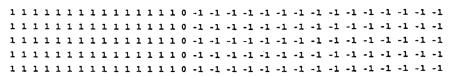
- Each row of the mask is devised in such a way as to contain L contiguous elements having a positive value, for example 1, while the other elements of the row have a value of opposite sign, for example -1, so as to define a correspondence, respectively, with the light zones (road stripes) and dark zones (asphalt) of the portion of the image.
- each row further comprises one or more elements of value 0 contiguous with the L elements of value 1; these elements render the method of recognition less sensitive to the characteristics of the transition zones between the road stripes and the asphalt.
- the number of columns of value 1 is high enough to define a correspondence with a portion both of the left marking stripes (inclined to the right) and of the right marking stripes (inclined to the left) of the road lanes. In this way, the mask becomes relatively insensitive to the exact orientation of the marking stripes; this makes it possible to use the same mask matrix both for the marking stripes to the left and those to the right of the road lanes.
- the mask matrix has a smaller number of rows than number of columns; this arrangement provides good sensitivity to the various orientations of the marking stripes of the road lanes without requiring the use of too large a number of columns of value 1.
- the elements of the convolved image matrix are strongly dependent on the discontinuities present in the road image, and are hardly sensitive to the absolute value of the luminosity; this provides comparable results under various conditions of illumination, for example during a sunny daytime period, at twilight, at night with artificial illumination.
- a typical example of a mask used in the method of recognition of the present invention is given by the following matrix:
- different portions of the road image are filtered using different masks, so as to take account of the apparent variation in amplitude of the marking stripes of the road lanes caused by perspective effects.
- the value L is modified in the course of the convolution operation, by subdividing the road images into various horizontal portions (for example 3 portions) and determining for each of them the width (in pixels) of the marking stripes and then modifying the mask matrix accordingly; the number of columns of value 1 thereby decreases on moving from the bottom to the top of the image.
- the columns of value 1 eliminated and a corresponding number of columns of value -1 are substituted by columns of value 0 or else the dimensions of the mask matrix are decreased.
- each element of the convolved image matrix is compared with a specified threshold value so as to determine a binary image matrix; the value of the threshold is chosen, within the real dynamic interval of the values of the elements of the convolved image matrix, on the basis of the ambient luminosity or of other parameters, possibly set by the user.
- a first binary value for example 0
- a second binary value for example 1 in the contrary case (white element).
- a representation of the marking stripes of the road lanes is determined; typically, two straight lines are determined corresponding to the marking stripes of the lane in which the vehicle in question is travelling. This phase is carried out using the steps described below; the person skilled in the art will appreciate that other equivalent known methods can however be used.
- an operation is performed for reducing the thickness of the lines (thinning) of the binary image matrix, by determining a vector S (thinned image) whose elements S k each consist of a pair of coordinates (x k , y k ) (column number and row number respectively) relating to the elements of the binary image matrix.
- this matrix is scanned row by row and, for each row, the horizontal contiguous groups of white elements (i.e. with value 1) are determined; a single element, typically the central element, is then extracted from each of these groups and its coordinates (row and column) are inserted into the vector S.
- the method determines the straight lines corresponding to the thinned image which are a candidate for recognition.
- this operation is performed by applying a Hough transform to the vector S.
- the Hough transform is a projection of a point in the plane with cartesian coordinates x,y into a curve in the plane with polar coordinates ⁇ , ⁇ , in which all the points on the same straight line in the x,y plane are projected into curves in the ⁇ , ⁇ plane which intersect at a point (unique point), which represents the straight line in the x,y plane.
- this transform generates a distribution of points of intersection; the point with greatest density is then chosen as unique point approximating the corresponding straight line.
- the Hough transform makes it possible to identify even non-continuous lines satisfactorily, as in the case of marking lines of road lanes.
- a discrete set of values of the angle ⁇ i is used, for example 20 values such as to cover an interval (for example of 70°) in which it is expected to find the straight lines corresponding to the respectively left and right marking stripes of the road lane in which the vehicle is travelling.
- Two accumulation vectors are used to contain the number of occurrences of each point at the coordinates ⁇ , ⁇ for, respectively, the left and right portion of the road image.
- the values below a specified threshold value are zeroed, so as to eliminate residual noise from the image.
- the determination of the candidate straight lines is performed by extracting the local maxima from the two accumulation vectors for, respectively, the left and right portion of the image. These values are then ordered in two lists, one for each straight line to be associated with the two marking stripes (left and right) of the road lane.
- the method goes lastly to block 24, in which two straight lines are selected, associated with the marking stripes of the road lane.
- This operation is performed by choosing the first candidates in the two lists described above which satisfy a few simple geometrical rules, for example they intersect at a vertical height inside a specified interval based on the known position of the horizon, they intersect the lower horizontal axis inside a predetermined interval, form an angle of intersection lower than a fixed value determined by the amplitude of the road lane, and the like.
- FIG. 3 A variant embodiment of the method of recognition described above is illustrated in Fig. 3 (blocks common to Fig. 2 are identified with the same reference numerals).
- the figure illustrates a method of recognition 26 in which the matrix of the road image acquired in block 12 is subjected, typically in parallel, to two convolution operations in blocks 28 and 30 respectively. These operations are performed by using two different masks; in particular, these masks are mutually specular, i.e.
- K1 i,j and K2 i,-j are the elements, respectively, of the first and of the second mask, and 2 ⁇ R+1 is the common number of columns thereof. Illustrated below is an example of the first mask: and of the second mask: which are used in this embodiment of the present invention.
- the convolved images produced in the two blocks 28 and 30 are then compared, in blocks 32 and 34 respectively, with a corresponding threshold value so as to obtain two distinct binary images; typically, the two threshold values are equal to one another. Then with reference to block 36, these binary images are joined in a single matrix via a logic AND operation performed between the corresponding elements of the two distinct binary images. The method then continues to the group of blocks 18 (with the corresponding blocks 20-24), by determining the straight lines corresponding to the marking stripes of the road lanes in a manner similar to that described earlier.
- This embodiment offers better performance with regard to the elimination of noise, because only double discontinuities (dark/light/dark) are picked out, typical of road marking lines, and renders the method insensitive to single luminous discontinuities (light/ dark), such as for example vertical shaded lines in the middle of the carriageway or other large-size vehicles (for example lorries) which are overtaking.
- FIG. 4 there is illustrated a basic diagram of an electronic device 100, described in European Patent Application N.96830525.0 of 15 October 1996, which can be used to embody the method of the present invention; in particular, this device embodies an artificial neural network which makes it possible to carry out the convolution operation between the image matrix and the mask matrix.
- the electronic device 100 comprises an input unit 102, connected to a bus 104, for example a 64-line bus, so as to receive binary values or bits (0-1) representative of the image matrix; commonly, the digital value 1 is represented by a positive supply voltage value Vdd (for example 5V, with respect to a reference or earth value), while the digital value 0 is represented by a 0V voltage value.
- Vdd positive supply voltage value
- Vdd for example 5V, with respect to a reference or earth value
- the input unit 102 consists of a plurality of shift registers 106-120, typically equal in number to the number of lines of the bus 104 (in the example in question 64, only 8 of which are represented in the figure).
- Each shift register 106-120 consists of a plurality of cells interlinked in the usual manner.
- the first cell of each shift register 106-120, indicated as the cell of the least significant bit (or LSB) is connected to a corresponding line of the bus 104 via a line 122-129 so as to receive as input the binary value present on the corresponding line of the bus 104; the insertion of this binary value causes a leftward shift in the figure, of the binary values contained in the shift register 106-120.
- each shift register 106-120 is connected to the first cell of the following shift register, by means of a line 130-137 (the last cell of the last shift register is connected to the first cell of the first shift register).
- a suitable configuration block (not shown in the figure) contained inside each shift register 106-120 enables a specific input (from the bus 104 or from the previous shift register) for loading the binary values thereinto. This makes it possible dynamically to vary the length and number of the shift registers of the device depending on the various applicational requirements.
- the shift registers 106-120 are connected, via lines 140, to a translator block 141, which transforms the voltage levels associated with the binary values contained in each cell of the shift registers 106-120; in particular, with the binary value 0 is associated a voltage value Vl (for example 2V), while with the binary value 1 is associated a voltage value Vh greater than Vl (for example 3V).
- Vl for example 2V
- Vh voltage value
- each synapse for example the synapse 142 shown in the figure, comprises a positive synapse 144 and a negative synapse 146 for storing, respectively, a positive weight and a negative weight.
- the synapses of each column are connected to the same line 152 and then, via the translator block 141, to the same cell of the shift registers 106-120 so as to receive as input the binary value contained in the cell, suitably transformed by the translator block 141.
- the synapses of each row are connected to a corresponding neuron 154, 156; in particular, the positive synapses and the negative synapses of each row are linked, respectively, to a line 158, 162 and to a line 160, 164 as input to the corresponding neuron 154, 156.
- Each positive synapse and each negative synapse consists of a memory cell which embodies a breaker element with programmable conductance, as described in European Patent Application N.95830433.9 of 13 October 1995.
- the breaker when the synapse receives as input a value corresponding to logic 0 (Vl), the breaker is open, so that its conductance is zero; when the input has a value corresponding to logic 1 (Vh), the breaker is closed and its conductance is equal to a value stored therein.
- the breaker consists of a field-effect transistor (MOSFET) with floating gate, and in particular of a cell of an EEPROM (or E 2 PROM) memory of flash type.
- MOSFET field-effect transistor
- the transistors 144, 146 have their source terminal linked to a reference terminal (earth); the gate terminal of the transistors 144, 146 of each column is linked to the same line 152; the drain terminals of the transistors making up the positive synapses 144 and the negative synapses 146 of each row are connected, respectively, to the corresponding line 158, 162 and 160, 162.
- Each transistor 144, 146 is programmed in such a way as to have a threshold voltage (Vt) correlated with the absolute value of the stored weight.
- a zero weight is associated with a threshold voltage Vt greater than the voltage Vh, in such a way that the transistor 144, 146 is always disabled (zero conductance) irrespective of the voltage applied to its gate terminal (Vl, Vh), i.e. of the logic value input (0, 1).
- the lower weight in terms of absolute value, stored in the transistors 144, 146 is associated a threshold voltage lower than the voltage Vh by a preset value (for example 32mV).
- a preset value for example 32mV.
- the transistor 144, 146 is disabled (zero conductance); when the voltage on the line 152 has value Vh (logic 1), the conductance of the transistor 144, 146 is proportional to the difference between the voltage Vh and the threshold voltage Vt. Consequently, the conductance of each transistor 144, 146 is correlated with the product of the binary value input and the stored weight.
- each line 158, 162 is correlated with the sum of the products of the inputs for the positive weights stored, while the total conductance of each line 160, 164 is correlated with the sum of the products of the inputs for the negative weights stored.
- Each neuron 154, 156 measures the total conductance of the synapses of the corresponding row and calculates a binary result dependent on this measurement.
- the neuron 154, 156 compares the total conductance of the positive synapses with the total conductance of the negative synapses of the corresponding row and produces the binary result as a function of this comparison, for example 1 if the total conductance of the negative synapses is greater than the total conductance of the positive synapses, or 0 in the contrary case.
- the neurons 154, 156 are connected to the bus 104, via lines 166, 168, so as to output these binary results; in the case of a number T of neurons (for example 256) greater than the number of lines of the bus 104, the neurons are connected to the bus 104 via a suitable multiplexer, not shown in the figure.
- the device 100 furthermore comprises an unbalance block 170 which makes it possible to vary the total conductance of the positive and negative synapses of each row in a predetermined manner.
- the unbalance block 170 comprises memory elements (latches) 172, for example 64, connected to the bus 104 via lines 174 so as to receive as input binary enabling values.
- Each memory element 172 is connected, via lines 176, to the translator block 141.
- the binary values contained in the memory elements 172 are supplied to a matrix of floating-gate field-effect transistors 180 suitably programmed in a manner similar to that described previously.
- the transistors 180 of each column are connected to the same line 176 and then, via the translator block 141, to the same memory element 172 so as to receive as input the binary value contained in the memory element 172, suitably transformed by the translator block 141; the transistors 180 of one and the same row are linked to a corresponding one of the lines 158, 164.
- transistor 180 When a transistor 180 receives as input a value corresponding to logic 0 (Vl), its conductance is always zero, so that it does not influence the total conductance of the line 158-164 to which it is linked; when a transistor 180 receives as input a value corresponding to logic 1 (Vh), its conductance is proportional to the difference between the voltage Vh and the threshold voltage Vt.
- Vl logic 0
- Vh logic 1
- the result output by the corresponding neuron 154, 156 will be 1 only if the conductance correlated with the sum of the products of the input values for the negative weights exceeds the conductance correlated with the sum of the products of the input values for the positive weights by an amount at least equal to the threshold ⁇ G.
- this characteristic makes it possible to obtain multi-bit results, by programming equal weights on rows of synapses linked to neurons with different thresholds, or else by exchanging the values in the memory elements 172 in successive calculation cycles with equal input values.
- Fig. 5 there is illustrated a circuit diagram of a neuron 154 used in the electronic device described above (elements common to Fig. 4 are identified with the same reference numerals); this structure is described in greater detail in European Patent Application N.95830433.9 cited earlier.
- the neuron 154 receives as input the total conductance of the positive and negative synapses of the corresponding row via, respectively, the line 158 and the line 160.
- the lines 158 and 160 are linked to a decoupling stage (buffer) 202, comprising two N-channel MOS transistors (nMOS) 204 and 206 having their gate terminals linked together; the source terminals of the transistors 204 and 206 are connected, respectively, to the lines 158 and 160, while the drain terminals define, respectively, an outward line 208 and 210 of the decoupling stage 202.
- the stage 202 comprises another nMOS transistor 212 diode-connected having its drain terminal linked to a positive supply terminal Vdd via a current generator 216; the gate terminal of the transistor 212 is linked to its own drain terminal and to the gate terminal of the transistors 204 and 206, while the source terminal is connected to the earth terminal.
- An electronic breaker 217 is linked between the gate terminals of the transistors 204, 206, 212 and the earth terminal; when this breaker is closed, the transistors 204, 206, 212 are disabled, in such a way as to eliminate the current in the corresponding synapses when the device is not in use.
- the breaker 217 jointly with a further breaker (not shown in the figure) in series with the current generator 216, makes it possible selectively to activate just the neurons actually used in a specified calculation cycle, therefore reducing the power consumption of the device.
- the decoupling stage 202 causes the capacitance seen by the lines 208 and 210 to be merely that defined by the transistors 204 and 206 and not the total capacitance of the in-parallel transistors making up the corresponding synapses which, considering the very large number of synapses generally present (up to a few thousand), may be extremely high; this makes the operation of the neuron 154 very fast, of the order of a thousand GCPS (Giga Connections Per Second).
- the decoupling stage 202 moreover maintains a low voltage level on the lines 158 and 160, in such a way that the entire device can operate with a low supply voltage level (of the order of a few V) and low consumption of power per operation (of the order of a few tens of GCPS/mW at the maximum speed of calculation).
- the neuron 154 comprises two symmetric sections 218 and 220 connected together and to the lines 208 and 210.
- the sections 218 and 220 each comprise three P-channel MOS transistors (pMOS), 222-226 and 228-232 respectively, having their source terminals linked to the supply terminal Vdd and their gate terminals interconnected.
- the transistors 226 and 232 are diode-connected, form a current mirror with the transistors, 222, 224 and 228, 230 respectively, and have their drain terminal linked to the lines 208 and 210, respectively.
- the drain terminals of the transistors 224 and 230 are linked to the lines 210 and 208, respectively; the drain terminals of the transistors 222 and 228 are connected to a latch circuit 234.
- Two electronic breakers 236 and 238 are linked between the supply terminal Vdd and the gate terminals of the transistors 222-226 and 228-232, respectively; when the device is not in use, these breakers are closed so as to keep the transistors 222-232 disabled.
- the latch circuit 234 comprises an nMOS transistor 236 having its source terminal and its drain terminal connected to the drain terminals of the transistors 222 and 228 respectively; the gate terminal forms a control input for an enable signal EN.
- the latch circuit 234 comprises two further nMOS transistors 238 and 240 having their drain terminal connected, respectively, to the source terminal and drain terminal of the transistor 236, their gate terminal linked, respectively, to the drain terminal and source terminal of the same transistor 236 and their source terminal connected to the earth terminal.
- the drain terminal of the transistor 240 defines the output line 166 of the neuron 154.
- the neuron 154 compares the conductances of the lines 158 and 160, by means of a comparison of the currents in the corresponding lines 208 and 210.
- the breakers 217, 236, 238 are open, these currents begin to flow in the sections 218 and 220 so as to bring them into conduction.
- the current mirrors of the two sections are not however activated at the same speed, but the current mirror connected to the line with greater conductance (larger current) is brought into conduction more speedily; assuming for example that the current in the line 208 (positive synapses) is greater than that in the line 210 (negative synapses), the transistors 224, 226 are activated more speedily than the transistors 230, 232.
- the enable signal EN disables the transistor 236, the transistor 240, whose gate terminal is connected to the active section 218 and hence to the supply terminal Vdd, is brought into conduction, connecting the output 166 to the earth terminal (logic 0).
- the section 220 and the transistor 238 are conducting, while the section 218 and the transistor 240 are disabled, so that the output 166 is connected to the supply terminal Vdd through the transistor 238 (logic 1).
- the value output on the line 166 is stored in a suitable memory element (not shown in the figure) and the computation in the neuron 154 is therefore switched off.
- the computation time of each neuron depends on the strength of the current in the section 218 and 220 and on their difference, in that larger currents reduce the activation times of the sections 218, 220 and hence the computation time of the neuron 154. Since the computation time of each neuron is not predictable a priori, it is fixed at a sufficiently high value so as to ensure correct computation in the various operational situations.
- the neuron 154 moreover comprises a logic block (not shown in the figure) for automatically timing the computation of this neuron 154.
- the enable signal EN disables the transistor 236, the voltage at the drain terminals of the transistors 238 and 240 begins to become unbalanced, until it is carried to a value Vdd on one of them and to a value 0V on the other.
- Vdd voltage of the terminal which is being carried to logic 1
- a threshold voltage corresponding to this value for example 2.5V
- the voltage of the terminal which is being carried to logic 0 (0V) falls below a threshold voltage corresponding to this value (for example 0.8V)
- the calculation cycle of the electronic device is terminated as soon as the last active neuron has terminated the computation. This makes it possible to increase the speed of the electronic device and to reduce its power consumption.
- the image matrix is scanned, typically from the top left corner (element I 1,1 ) to the bottom right corner (element I N,M ), and its elements are loaded into the input unit 102.
- the most significant bits (MSB) of the first row are loaded into the shift register 106; these data are inserted one column after the other (from left to right), by shifting (leftwards) the preexisting data in the shift register 106, until a number of columns equal to those of the mask matrix, i.e. 3 in the example in question (I 1,1(1) , I 1,2(1) , I 1,3(1) ), are inserted.
- the second most significant bits (MSB-1) of the first row (I 1,1(2) , I 1,2(2) , I 1,3(2) ) are loaded into the shift register 108, and so on until the least significant bits (LSB) thereof are inserted.
- the elements of the second row of the image matrix are loaded into the shift registers 110, 112 etc., those of the third row into the shift registers 114, 116 etc., those of the fourth into the shift registers 118, 120 etc., and so on.
- the number of rows of the image matrix which is loaded in parallel into the input unit 102 is at least equal to the number of rows of the mask matrix, i.e. 3 in the example illustrated; the loading of further rows advantageously makes it possible (in the case of a matrix of synapses with more than one row) to increase the degree of parallelism of the convolution operation, as described in detail below.
- weights equal to the halved values of the elements of the first row of the mask matrix, in such a way as correctly to take into account the value of the bits (MSB-1) loaded into the shift register 108, and so on up to the synapses linked to the shift register into which the least significant bits (LSB) of the first row of the image matrix are loaded.
- stored in the synapses of the first row which are linked to the cells of the shift registers 110, 112 etc. are weights correlated with the elements of the second row of the mask matrix, and stored in the synapses linked to the cells of the shift registers 114, 116 etc.
- the other synapses of the first row which are not needed for storing weights correlated with the mask matrix are programmed to 0, in such a way that the values present in the shift registers in relation to columns which are not used for the mask matrix do not yield any uncontrolled contribution to the result.
- the neuron 154 linked to the first row of synapses thus produces as output on the bus 104 the first result of the first row (C 1,1 ) of the convolution operation.
- Weights correlated with the mask matrix are stored also in the synapses of the second row, similar to what was described previously but in such a way as to disregard the first row of the image matrix.
- stored in the synapses of the second row which are linked to the cells of the shift registers 110, 112, etc. are weights correlated with the elements of the first row of the mask matrix
- stored in the synapses linked to the cells of the shift registers 114, 116, etc. are weights correlated with the elements of the second row
- stored in the synapses linked to the cells of the shift registers 118, 120, etc. are weights correlated with the elements of the third row; the other synapses of the second row are programmed to 0.
- a third row of synapses corresponding to a third neuron are suitably programmed in such a way as to store weights correlated with the mask matrix shifted downwards by two rows, and so on.
- MaxPar INT(T/L) - P + 1
- L the depth of the image matrix
- P the number of rows of the mask matrix
Landscapes
- Engineering & Computer Science (AREA)
- Physics & Mathematics (AREA)
- Radar, Positioning & Navigation (AREA)
- Multimedia (AREA)
- Electromagnetism (AREA)
- Aviation & Aerospace Engineering (AREA)
- Computer Vision & Pattern Recognition (AREA)
- Remote Sensing (AREA)
- General Physics & Mathematics (AREA)
- Automation & Control Theory (AREA)
- Image Processing (AREA)
- Traffic Control Systems (AREA)
- Image Analysis (AREA)
- Road Signs Or Road Markings (AREA)
Abstract
Description


Claims (19)
- Method (10), in a system (2) for aiding the guidance of a vehicle, for identifying marking stripes demarcating at least one road lane in a road image represented by a matrix of elements each indicative of the luminosity level of an elementary portion of the image, the method (10) comprising the phases of:setting (14) a mask matrix and determining a convolved image matrix via a convolution operation between the matrix of the road image and the mask matrix so as to identify luminosity discontinuities present in the image,determining (16) a binary image matrix in which each element has a first (0) or a second (1) binary value depending on the result of a comparison of a corresponding element of the convolved image matrix with a threshold value,determining (18) from the binary image matrix a representation of the marking stripes,
characterized in thatthe phase of setting the mask matrix includes determining a value L indicative of the number of elements of the image matrix corresponding to the width of the marking stripes, each row of the mask matrix comprising L contiguous elements having a first value, the other elements of the row having a second value of opposite sign to the first value. - Method according to Claim 1, in which the first value is 1 and the second value is -1.
- Method according to Claim 1 or 2, in which each row of the mask matrix comprises at least one element of value 0 contiguous with the L elements.
- Method according to any one of Claims 1 to 3, in which the mask matrix has a substantially zero mean value.
- Method according to any one of Claims 1 to 4, in which the elements of each row of the mask matrix which are equidistant from the ends of the row are equal.
- Method according to any one of Claims 1 to 5, in which the elements of the mask matrix which belong to one and the same column are equal.
- Method according to any one of Claims 1 to 6, in which the mask matrix has a smaller number of rows than number of columns.
- Method according to Claim 7, in which the mask matrix has a number of rows lying between 3 and 8 and a number of columns lying between 20 and 40.
- Method according to any one of Claims 1 to 8, further comprising the phase of modifying at least once during the convolution operation the value L and the contents of the mask matrix.
- Method according to Claim 9, in which the value L is modified twice during the convolution operation.
- Method according to Claim 9 or 10, in which the dimensions of the mask matrix are modified in relation with the modification of the value L.
- Method (26), in a system (2) for aiding the guidance of a vehicle, for identifying marking stripes demarcating at least one road lane in a road image represented by a matrix of elements each indicative of the luminosity level of an elementary portion of the image, the method (26) comprising the phases of:determining a first (28) and a second (30) convolved image matrix via a convolution operation between the matrix of the road image and, respectively, a first and a second mask matrix so as to identify luminosity discontinuities present in the image, the elements of each row of the second mask matrix being equal in reverse order to the elements of a corresponding row of the first mask matrix,determining a first (32) and a second (34) binary image matrix in which each element has a first (0) or a second (1) binary value depending on the result of a comparison of a corresponding element, respectively, of the first and of the second convolved image matrix with, respectively, a first and a second threshold value,determining (36) a single binary image matrix via a logic AND operation between the corresponding elements of the first and of the second binary image matrix,determining (18) from the single binary image matrix a representation of the marking stripes.
- Method according to Claim 12, in which the elements of a left half of the first mask matrix have a first value and the elements of a right half of the first mask matrix have a second value of opposite sign to the first value.
- Method according to Claim 13, in which the first value is 1 and the second value is -1.
- Method according to Claim 13 or 14, in which the first mask matrix comprises at least one column of elements of value 0 lying between the left half and the right half.
- Method according to any one of Claims 12 to 15, in which the first and the second mask matrix have a substantially zero mean value.
- Method according to any one of Claims 12 to 16, in which the first and the second mask matrix have a smaller number of rows than number of columns.
- Method according to Claim 17, in which the first and the second mask matrix have a number of rows lying between 3 and 8 and a number of columns lying between 20 and 40.
- Method according to any one of Claims 12 to 18, in which the first and the second threshold value are equal.
Applications Claiming Priority (2)
| Application Number | Priority Date | Filing Date | Title |
|---|---|---|---|
| ITMI962154 | 1996-10-17 | ||
| IT96MI002154A IT1284976B1 (en) | 1996-10-17 | 1996-10-17 | METHOD FOR THE IDENTIFICATION OF SIGN STRIPES OF ROAD LANES |
Publications (3)
| Publication Number | Publication Date |
|---|---|
| EP0837378A2 true EP0837378A2 (en) | 1998-04-22 |
| EP0837378A3 EP0837378A3 (en) | 1998-05-06 |
| EP0837378B1 EP0837378B1 (en) | 2001-07-04 |
Family
ID=11375052
Family Applications (1)
| Application Number | Title | Priority Date | Filing Date |
|---|---|---|---|
| EP97203126A Expired - Lifetime EP0837378B1 (en) | 1996-10-17 | 1997-10-08 | Method for identifying marking stripes of road lanes |
Country Status (5)
| Country | Link |
|---|---|
| US (1) | US6212287B1 (en) |
| EP (1) | EP0837378B1 (en) |
| JP (1) | JPH10214345A (en) |
| DE (1) | DE69705478D1 (en) |
| IT (1) | IT1284976B1 (en) |
Cited By (1)
| Publication number | Priority date | Publication date | Assignee | Title |
|---|---|---|---|---|
| CN113808098A (en) * | 2021-09-14 | 2021-12-17 | 丰图科技(深圳)有限公司 | Road disease identification method, device, electronic device and readable storage medium |
Families Citing this family (17)
| Publication number | Priority date | Publication date | Assignee | Title |
|---|---|---|---|---|
| US6591000B1 (en) * | 1998-04-21 | 2003-07-08 | Denso Corporation | Apparatus and method for preprocessing a picked-up image, lane mark recognizing system, related vehicle traveling control system, and recording media |
| DE19842572B4 (en) * | 1998-09-17 | 2005-03-24 | Heidelberger Druckmaschinen Ag | Method for the automatic removal of image defects |
| US6819779B1 (en) * | 2000-11-22 | 2004-11-16 | Cognex Corporation | Lane detection system and apparatus |
| US7062476B2 (en) * | 2002-06-17 | 2006-06-13 | The Boeing Company | Student neural network |
| US20040160595A1 (en) * | 2003-02-14 | 2004-08-19 | Lafarge Road Marking, Inc. | Road marking evaluation and measurement system |
| JP4437714B2 (en) * | 2004-07-15 | 2010-03-24 | 三菱電機株式会社 | Lane recognition image processing device |
| JP4659631B2 (en) * | 2005-04-26 | 2011-03-30 | 富士重工業株式会社 | Lane recognition device |
| US20090284361A1 (en) * | 2008-05-19 | 2009-11-19 | John Boddie | Driver scoring system with lane changing detection and warning system |
| JP5183392B2 (en) * | 2008-09-25 | 2013-04-17 | キヤノン株式会社 | Image processing apparatus, image processing method, and program |
| US20110248995A1 (en) * | 2010-04-09 | 2011-10-13 | Fuji Xerox Co., Ltd. | System and methods for creating interactive virtual content based on machine analysis of freeform physical markup |
| US20130027416A1 (en) * | 2011-07-25 | 2013-01-31 | Karthikeyan Vaithianathan | Gather method and apparatus for media processing accelerators |
| US9384394B2 (en) | 2013-10-31 | 2016-07-05 | Toyota Motor Engineering & Manufacturing North America, Inc. | Method for generating accurate lane level maps |
| EP3098753A1 (en) | 2015-05-28 | 2016-11-30 | Tata Consultancy Services Limited | Lane detection |
| CN109960959B (en) * | 2017-12-14 | 2020-04-03 | 百度在线网络技术(北京)有限公司 | Method and apparatus for processing image |
| CN110796606B (en) * | 2018-08-01 | 2023-07-07 | 新疆万兴信息科技有限公司 | Method, device, electronic equipment and medium for determining IPM matrix parameters |
| CN111508239B (en) * | 2020-04-16 | 2022-03-01 | 成都旸谷信息技术有限公司 | Intelligent vehicle flow identification method and system based on mask matrix |
| DE102021202036A1 (en) | 2021-03-03 | 2022-09-08 | Robert Bosch Gesellschaft mit beschränkter Haftung | Method and device for determining a transverse position value indicating the transverse position of a motor vehicle in a lane |
Family Cites Families (5)
| Publication number | Priority date | Publication date | Assignee | Title |
|---|---|---|---|---|
| FR2674354A1 (en) * | 1991-03-22 | 1992-09-25 | Thomson Csf | Method of analysing sequences of road images, device for implementing it and its application to obstacle detection |
| JP3073599B2 (en) * | 1992-04-22 | 2000-08-07 | 本田技研工業株式会社 | Image edge detection device |
| JP3083918B2 (en) * | 1992-06-26 | 2000-09-04 | 本田技研工業株式会社 | Image processing device |
| JP3169483B2 (en) * | 1993-06-25 | 2001-05-28 | 富士通株式会社 | Road environment recognition device |
| JP3357749B2 (en) * | 1994-07-12 | 2002-12-16 | 本田技研工業株式会社 | Vehicle road image processing device |
-
1996
- 1996-10-17 IT IT96MI002154A patent/IT1284976B1/en active IP Right Grant
-
1997
- 1997-10-08 EP EP97203126A patent/EP0837378B1/en not_active Expired - Lifetime
- 1997-10-08 DE DE69705478T patent/DE69705478D1/en not_active Expired - Lifetime
- 1997-10-17 JP JP9285819A patent/JPH10214345A/en active Pending
- 1997-10-17 US US08/951,956 patent/US6212287B1/en not_active Expired - Lifetime
Cited By (1)
| Publication number | Priority date | Publication date | Assignee | Title |
|---|---|---|---|---|
| CN113808098A (en) * | 2021-09-14 | 2021-12-17 | 丰图科技(深圳)有限公司 | Road disease identification method, device, electronic device and readable storage medium |
Also Published As
| Publication number | Publication date |
|---|---|
| ITMI962154A1 (en) | 1998-04-17 |
| IT1284976B1 (en) | 1998-05-28 |
| EP0837378A3 (en) | 1998-05-06 |
| JPH10214345A (en) | 1998-08-11 |
| US6212287B1 (en) | 2001-04-03 |
| DE69705478D1 (en) | 2001-08-09 |
| EP0837378B1 (en) | 2001-07-04 |
Similar Documents
| Publication | Publication Date | Title |
|---|---|---|
| EP0837378B1 (en) | Method for identifying marking stripes of road lanes | |
| KR102177880B1 (en) | Class labeling apparatus for autonomous driving | |
| US12423931B2 (en) | Simulation scene image generation method, electronic device and storage medium | |
| US9286524B1 (en) | Multi-task deep convolutional neural networks for efficient and robust traffic lane detection | |
| Nguyen et al. | Learning framework for robust obstacle detection, recognition, and tracking | |
| Milford et al. | Vision‐based simultaneous localization and mapping in changing outdoor environments | |
| Seeger et al. | Towards road type classification with occupancy grids | |
| US12062242B2 (en) | Method and system for real-time continuous lane mapping and classification | |
| Yao et al. | DevNet: Deviation aware network for lane detection | |
| JPH10134033A (en) | Electronic device for performing convolution operations | |
| CN117636298A (en) | Vehicle re-identification method, system and storage medium based on multi-scale feature learning | |
| Ye et al. | Neural network‐based semantic segmentation model for robot perception of driverless vision | |
| Ozaki et al. | DNN-based self-attitude estimation by learning landscape information | |
| Kim et al. | Design and implementation of the vehicular camera system using deep neural network compression | |
| Alhammadi et al. | Thermal-Based Vehicle Detection System using Deep Transfer Learning under Extreme Weather Conditions | |
| CN116993781B (en) | Multimodal visual tracking method and system based on monitoring scene | |
| CN114120259A (en) | A kind of empty parking space identification method and its system, computer equipment, storage medium | |
| Rim et al. | Radar-guided polynomial fitting for metric depth estimation | |
| Zin et al. | Robust road sign recognition using standard deviation | |
| Vishwakarma et al. | Two‐dimensional DFT with sliding and hopping windows for edge map generation of road images | |
| Wang et al. | A Novel Lane Model for Lane Boundary Detection. | |
| Ahmed et al. | Lane marking detection techniques for autonomous driving | |
| Shinwook et al. | Neuromorphic hardware accelerated lane detection system | |
| Schonfeld et al. | Image processing board for real-time extraction of line symbols from video sequences for AGV | |
| Liu et al. | Advnet: Multi-task fusion of object detection and semantic segmentation |
Legal Events
| Date | Code | Title | Description |
|---|---|---|---|
| PUAI | Public reference made under article 153(3) epc to a published international application that has entered the european phase |
Free format text: ORIGINAL CODE: 0009012 |
|
| PUAL | Search report despatched |
Free format text: ORIGINAL CODE: 0009013 |
|
| AK | Designated contracting states |
Kind code of ref document: A2 Designated state(s): DE FR GB IT |
|
| AX | Request for extension of the european patent |
Free format text: AL;LT;LV;RO;SI |
|
| AK | Designated contracting states |
Kind code of ref document: A3 Designated state(s): AT BE CH DE DK ES FI FR GB GR IE IT LI LU MC NL PT SE |
|
| AX | Request for extension of the european patent |
Free format text: AL;LT;LV;RO;SI |
|
| RAP3 | Party data changed (applicant data changed or rights of an application transferred) |
Owner name: STMICROELECTRONICS S.R.L. |
|
| 17P | Request for examination filed |
Effective date: 19981102 |
|
| AKX | Designation fees paid |
Free format text: DE FR GB IT |
|
| RBV | Designated contracting states (corrected) |
Designated state(s): DE FR GB IT |
|
| GRAG | Despatch of communication of intention to grant |
Free format text: ORIGINAL CODE: EPIDOS AGRA |
|
| 17Q | First examination report despatched |
Effective date: 20001016 |
|
| GRAG | Despatch of communication of intention to grant |
Free format text: ORIGINAL CODE: EPIDOS AGRA |
|
| GRAH | Despatch of communication of intention to grant a patent |
Free format text: ORIGINAL CODE: EPIDOS IGRA |
|
| GRAH | Despatch of communication of intention to grant a patent |
Free format text: ORIGINAL CODE: EPIDOS IGRA |
|
| GRAA | (expected) grant |
Free format text: ORIGINAL CODE: 0009210 |
|
| AK | Designated contracting states |
Kind code of ref document: B1 Designated state(s): DE FR GB IT |
|
| REF | Corresponds to: |
Ref document number: 69705478 Country of ref document: DE Date of ref document: 20010809 |
|
| ITF | It: translation for a ep patent filed | ||
| PGFP | Annual fee paid to national office [announced via postgrant information from national office to epo] |
Ref country code: DE Payment date: 20011004 Year of fee payment: 5 |
|
| PG25 | Lapsed in a contracting state [announced via postgrant information from national office to epo] |
Ref country code: DE Free format text: LAPSE BECAUSE OF FAILURE TO SUBMIT A TRANSLATION OF THE DESCRIPTION OR TO PAY THE FEE WITHIN THE PRESCRIBED TIME-LIMIT Effective date: 20011005 |
|
| ET | Fr: translation filed | ||
| REG | Reference to a national code |
Ref country code: GB Ref legal event code: IF02 |
|
| PLBE | No opposition filed within time limit |
Free format text: ORIGINAL CODE: 0009261 |
|
| STAA | Information on the status of an ep patent application or granted ep patent |
Free format text: STATUS: NO OPPOSITION FILED WITHIN TIME LIMIT |
|
| 26N | No opposition filed | ||
| PGFP | Annual fee paid to national office [announced via postgrant information from national office to epo] |
Ref country code: FR Payment date: 20050831 Year of fee payment: 9 |
|
| PGFP | Annual fee paid to national office [announced via postgrant information from national office to epo] |
Ref country code: GB Payment date: 20060926 Year of fee payment: 10 |
|
| PGFP | Annual fee paid to national office [announced via postgrant information from national office to epo] |
Ref country code: IT Payment date: 20061031 Year of fee payment: 10 |
|
| GBPC | Gb: european patent ceased through non-payment of renewal fee |
Effective date: 20071008 |
|
| REG | Reference to a national code |
Ref country code: FR Ref legal event code: ST Effective date: 20080630 |
|
| PG25 | Lapsed in a contracting state [announced via postgrant information from national office to epo] |
Ref country code: GB Free format text: LAPSE BECAUSE OF NON-PAYMENT OF DUE FEES Effective date: 20071008 |
|
| PG25 | Lapsed in a contracting state [announced via postgrant information from national office to epo] |
Ref country code: FR Free format text: LAPSE BECAUSE OF NON-PAYMENT OF DUE FEES Effective date: 20071031 |
|
| PG25 | Lapsed in a contracting state [announced via postgrant information from national office to epo] |
Ref country code: FR Free format text: LAPSE BECAUSE OF NON-PAYMENT OF DUE FEES Effective date: 20061031 |
|
| PG25 | Lapsed in a contracting state [announced via postgrant information from national office to epo] |
Ref country code: IT Free format text: LAPSE BECAUSE OF NON-PAYMENT OF DUE FEES Effective date: 20071008 |