EP0837147A2 - A method for manufacturing a stainless steel strip - Google Patents
A method for manufacturing a stainless steel strip Download PDFInfo
- Publication number
- EP0837147A2 EP0837147A2 EP97203013A EP97203013A EP0837147A2 EP 0837147 A2 EP0837147 A2 EP 0837147A2 EP 97203013 A EP97203013 A EP 97203013A EP 97203013 A EP97203013 A EP 97203013A EP 0837147 A2 EP0837147 A2 EP 0837147A2
- Authority
- EP
- European Patent Office
- Prior art keywords
- strip
- cold
- thickness
- rolling
- stainless steel
- Prior art date
- Legal status (The legal status is an assumption and is not a legal conclusion. Google has not performed a legal analysis and makes no representation as to the accuracy of the status listed.)
- Withdrawn
Links
- 238000000034 method Methods 0.000 title claims abstract description 54
- 238000004519 manufacturing process Methods 0.000 title claims abstract description 27
- 229910001220 stainless steel Inorganic materials 0.000 title claims abstract description 19
- 239000010935 stainless steel Substances 0.000 title claims abstract description 18
- 238000005097 cold rolling Methods 0.000 claims abstract description 42
- 238000000137 annealing Methods 0.000 claims abstract description 31
- 230000009467 reduction Effects 0.000 claims abstract description 30
- 238000005266 casting Methods 0.000 claims abstract description 21
- 230000008569 process Effects 0.000 claims abstract description 16
- 238000005098 hot rolling Methods 0.000 claims abstract description 14
- 238000005482 strain hardening Methods 0.000 claims abstract description 14
- 238000001816 cooling Methods 0.000 claims abstract description 11
- 229910000963 austenitic stainless steel Inorganic materials 0.000 claims abstract description 9
- 229910000831 Steel Inorganic materials 0.000 claims description 14
- 239000010959 steel Substances 0.000 claims description 14
- 239000000463 material Substances 0.000 claims description 5
- 238000005452 bending Methods 0.000 claims description 4
- 229910052750 molybdenum Inorganic materials 0.000 claims description 4
- 229910052759 nickel Inorganic materials 0.000 claims description 2
- 238000003825 pressing Methods 0.000 claims 2
- 238000005554 pickling Methods 0.000 description 10
- 238000010438 heat treatment Methods 0.000 description 5
- 239000000047 product Substances 0.000 description 5
- 238000011144 upstream manufacturing Methods 0.000 description 5
- 238000005422 blasting Methods 0.000 description 4
- 238000007796 conventional method Methods 0.000 description 3
- 230000006872 improvement Effects 0.000 description 3
- 238000005096 rolling process Methods 0.000 description 3
- 238000003466 welding Methods 0.000 description 3
- ZOKXTWBITQBERF-UHFFFAOYSA-N Molybdenum Chemical compound [Mo] ZOKXTWBITQBERF-UHFFFAOYSA-N 0.000 description 2
- PXHVJJICTQNCMI-UHFFFAOYSA-N Nickel Chemical compound [Ni] PXHVJJICTQNCMI-UHFFFAOYSA-N 0.000 description 2
- 230000008901 benefit Effects 0.000 description 2
- 239000007795 chemical reaction product Substances 0.000 description 2
- 239000004035 construction material Substances 0.000 description 2
- 239000011733 molybdenum Substances 0.000 description 2
- 238000001953 recrystallisation Methods 0.000 description 2
- 238000010008 shearing Methods 0.000 description 2
- 238000007711 solidification Methods 0.000 description 2
- 230000008023 solidification Effects 0.000 description 2
- -1 5-15% molybdenum Chemical compound 0.000 description 1
- 229910045601 alloy Inorganic materials 0.000 description 1
- 239000000956 alloy Substances 0.000 description 1
- 230000005540 biological transmission Effects 0.000 description 1
- 230000015572 biosynthetic process Effects 0.000 description 1
- 230000003750 conditioning effect Effects 0.000 description 1
- 238000010276 construction Methods 0.000 description 1
- 238000009749 continuous casting Methods 0.000 description 1
- 238000010924 continuous production Methods 0.000 description 1
- 238000005520 cutting process Methods 0.000 description 1
- 230000001419 dependent effect Effects 0.000 description 1
- 238000013461 design Methods 0.000 description 1
- 230000000694 effects Effects 0.000 description 1
- 238000005259 measurement Methods 0.000 description 1
- 238000012986 modification Methods 0.000 description 1
- 230000004048 modification Effects 0.000 description 1
- 235000021110 pickles Nutrition 0.000 description 1
- 238000012545 processing Methods 0.000 description 1
- 238000005204 segregation Methods 0.000 description 1
- 229910001256 stainless steel alloy Inorganic materials 0.000 description 1
- 238000003860 storage Methods 0.000 description 1
- 239000000126 substance Substances 0.000 description 1
- 238000004804 winding Methods 0.000 description 1
Images


Classifications
-
- B—PERFORMING OPERATIONS; TRANSPORTING
- B21—MECHANICAL METAL-WORKING WITHOUT ESSENTIALLY REMOVING MATERIAL; PUNCHING METAL
- B21B—ROLLING OF METAL
- B21B3/00—Rolling materials of special alloys so far as the composition of the alloy requires or permits special rolling methods or sequences ; Rolling of aluminium, copper, zinc or other non-ferrous metals
- B21B3/02—Rolling special iron alloys, e.g. stainless steel
-
- B—PERFORMING OPERATIONS; TRANSPORTING
- B21—MECHANICAL METAL-WORKING WITHOUT ESSENTIALLY REMOVING MATERIAL; PUNCHING METAL
- B21B—ROLLING OF METAL
- B21B1/00—Metal-rolling methods or mills for making semi-finished products of solid or profiled cross-section; Sequence of operations in milling trains; Layout of rolling-mill plant, e.g. grouping of stands; Succession of passes or of sectional pass alternations
- B21B1/22—Metal-rolling methods or mills for making semi-finished products of solid or profiled cross-section; Sequence of operations in milling trains; Layout of rolling-mill plant, e.g. grouping of stands; Succession of passes or of sectional pass alternations for rolling plates, strips, bands or sheets of indefinite length
- B21B1/24—Metal-rolling methods or mills for making semi-finished products of solid or profiled cross-section; Sequence of operations in milling trains; Layout of rolling-mill plant, e.g. grouping of stands; Succession of passes or of sectional pass alternations for rolling plates, strips, bands or sheets of indefinite length in a continuous or semi-continuous process
- B21B1/28—Metal-rolling methods or mills for making semi-finished products of solid or profiled cross-section; Sequence of operations in milling trains; Layout of rolling-mill plant, e.g. grouping of stands; Succession of passes or of sectional pass alternations for rolling plates, strips, bands or sheets of indefinite length in a continuous or semi-continuous process by cold-rolling, e.g. Steckel cold mill
-
- B—PERFORMING OPERATIONS; TRANSPORTING
- B21—MECHANICAL METAL-WORKING WITHOUT ESSENTIALLY REMOVING MATERIAL; PUNCHING METAL
- B21B—ROLLING OF METAL
- B21B1/00—Metal-rolling methods or mills for making semi-finished products of solid or profiled cross-section; Sequence of operations in milling trains; Layout of rolling-mill plant, e.g. grouping of stands; Succession of passes or of sectional pass alternations
- B21B1/46—Metal-rolling methods or mills for making semi-finished products of solid or profiled cross-section; Sequence of operations in milling trains; Layout of rolling-mill plant, e.g. grouping of stands; Succession of passes or of sectional pass alternations for rolling metal immediately subsequent to continuous casting
-
- B—PERFORMING OPERATIONS; TRANSPORTING
- B21—MECHANICAL METAL-WORKING WITHOUT ESSENTIALLY REMOVING MATERIAL; PUNCHING METAL
- B21B—ROLLING OF METAL
- B21B37/00—Control devices or methods specially adapted for metal-rolling mills or the work produced thereby
- B21B37/28—Control of flatness or profile during rolling of strip, sheets or plates
- B21B37/38—Control of flatness or profile during rolling of strip, sheets or plates using roll bending
-
- B—PERFORMING OPERATIONS; TRANSPORTING
- B21—MECHANICAL METAL-WORKING WITHOUT ESSENTIALLY REMOVING MATERIAL; PUNCHING METAL
- B21B—ROLLING OF METAL
- B21B45/00—Devices for surface or other treatment of work, specially combined with or arranged in, or specially adapted for use in connection with, metal-rolling mills
-
- C—CHEMISTRY; METALLURGY
- C21—METALLURGY OF IRON
- C21D—MODIFYING THE PHYSICAL STRUCTURE OF FERROUS METALS; GENERAL DEVICES FOR HEAT TREATMENT OF FERROUS OR NON-FERROUS METALS OR ALLOYS; MAKING METAL MALLEABLE, e.g. BY DECARBURISATION OR TEMPERING
- C21D8/00—Modifying the physical properties by deformation combined with, or followed by, heat treatment
- C21D8/02—Modifying the physical properties by deformation combined with, or followed by, heat treatment during manufacturing of plates or strips
- C21D8/0205—Modifying the physical properties by deformation combined with, or followed by, heat treatment during manufacturing of plates or strips of ferrous alloys
-
- B—PERFORMING OPERATIONS; TRANSPORTING
- B21—MECHANICAL METAL-WORKING WITHOUT ESSENTIALLY REMOVING MATERIAL; PUNCHING METAL
- B21B—ROLLING OF METAL
- B21B2261/00—Product parameters
- B21B2261/20—Temperature
-
- B—PERFORMING OPERATIONS; TRANSPORTING
- B21—MECHANICAL METAL-WORKING WITHOUT ESSENTIALLY REMOVING MATERIAL; PUNCHING METAL
- B21B—ROLLING OF METAL
- B21B2265/00—Forming parameters
- B21B2265/14—Reduction rate
-
- B—PERFORMING OPERATIONS; TRANSPORTING
- B21—MECHANICAL METAL-WORKING WITHOUT ESSENTIALLY REMOVING MATERIAL; PUNCHING METAL
- B21B—ROLLING OF METAL
- B21B2265/00—Forming parameters
- B21B2265/18—Elongation
-
- B—PERFORMING OPERATIONS; TRANSPORTING
- B21—MECHANICAL METAL-WORKING WITHOUT ESSENTIALLY REMOVING MATERIAL; PUNCHING METAL
- B21B—ROLLING OF METAL
- B21B41/00—Guiding, conveying, or accumulating easily-flexible work, e.g. wire, sheet metal bands, in loops or curves; Loop lifters
-
- C—CHEMISTRY; METALLURGY
- C21—METALLURGY OF IRON
- C21D—MODIFYING THE PHYSICAL STRUCTURE OF FERROUS METALS; GENERAL DEVICES FOR HEAT TREATMENT OF FERROUS OR NON-FERROUS METALS OR ALLOYS; MAKING METAL MALLEABLE, e.g. BY DECARBURISATION OR TEMPERING
- C21D8/00—Modifying the physical properties by deformation combined with, or followed by, heat treatment
- C21D8/02—Modifying the physical properties by deformation combined with, or followed by, heat treatment during manufacturing of plates or strips
- C21D8/0221—Modifying the physical properties by deformation combined with, or followed by, heat treatment during manufacturing of plates or strips characterised by the working steps
- C21D8/0236—Cold rolling
-
- C—CHEMISTRY; METALLURGY
- C21—METALLURGY OF IRON
- C21D—MODIFYING THE PHYSICAL STRUCTURE OF FERROUS METALS; GENERAL DEVICES FOR HEAT TREATMENT OF FERROUS OR NON-FERROUS METALS OR ALLOYS; MAKING METAL MALLEABLE, e.g. BY DECARBURISATION OR TEMPERING
- C21D8/00—Modifying the physical properties by deformation combined with, or followed by, heat treatment
- C21D8/02—Modifying the physical properties by deformation combined with, or followed by, heat treatment during manufacturing of plates or strips
- C21D8/0247—Modifying the physical properties by deformation combined with, or followed by, heat treatment during manufacturing of plates or strips characterised by the heat treatment
- C21D8/0268—Modifying the physical properties by deformation combined with, or followed by, heat treatment during manufacturing of plates or strips characterised by the heat treatment between cold rolling steps
Definitions
- the present invention relates to a method for manufacturing a stainless steel strip, particularly an austenitic stainless steel strip, with desired final thickness and a yield strength of at least 250 N/mm 2 .
- the manufacturing of stainless steel strips having a yield strength of at least 250 N/mm 2 conventionally includes casting an elongated product to obtain a strand, cutting the strand into slabs, and hot-rolling the slabs to form strips. After surface conditioning the strips, including among other things pickling the strip, the hot-rolled strips can be used without further thickness reduction in certain applications. However, subsequent cold-rolling ofthe hot-rolled strips is required in many other applications. This subsequent cold-rolling process is intended to achieve one or more or all ofthe following effects, viz. to further reduce the thickness ofthe strips, to enhance the mechanical strength and/or to improve the surfaces ofthe strips.
- the hot-rolled strips are annealed and pickled, and scrap-ends are welded onto both ends ofthe strips.
- the actual cold-rolling process is carried out conventionally in several passes through a cold-rolling mill, therewith enabling the thickness to be reduced by up to about 80%, normally 10-60%, for instance for cold-rolled strips which are intended for use as construction materials after having been slit into narrower strands.
- the scrap-ends must be removed before the strip can finally be coiled.
- the object ofthe invention is to produce, in a rational and cost efficient way, stainless steel strips, particularly stainless austenitic steel strips, having a desired thin thickness and a higher mechanical strength than that achieved in the conventional manufacture of hot- and cold-rolled stainless austenitic steel strips while obtaining an acceptable surface finish at the same time.
- This process step which can be performed through a technique known per se, provides a fast solidification ofthe steel which in turn may give a cast structure of the steel which can promote the achievement of desirable properties at the end product of the method.
- the cast structure will be fine grained as compared to structures obtained by conventional ingot casting or conventional continuos strand casting. If, for example, as is recommended in the method of the invention, use is made of a twin-roll strip caster, the strip cast structure would normally contain regions of columnar grains adjacent to the surfaces ofthe strip and a central equiaxed region.
- the following steps ofthe method of the invention are performed in a mode such that the advantage of the fine grained cast structure can be taken care of to achieve desirable features for the end product of the method.
- the strip casting may also allow for manufacturing strips of stainless steel alloys which are very difficult or even impossible to manufacture according to conventional techniques because of embrittlement or other problems attributed to the segregation or formation of undesirable phases in the steel or other phenomena.
- the cooling ofthe cast strip which can be performed comparatively fast due to the thin gange ofthe cast strip, can contribute to the desired results.
- the cast strip is cold-rolled with at least a 10% thickness reduction to a thickness which is at least 2% and at most 20% greater than the intended final thickness ofthe finished product, whereupon follows annealing the thus cold-rolled strip at a temperature of between 1,050°C and 1,250°C; and cold-working the strip after said annealing process so as to permanently elongate the strip and therewith reduce its thickness by 2-20%.
- At least some ofthe said objects can be achieved by continuously casting the stainless steel to obtain an elongated cast product, hot-rolling said elongated cast product to the shape of a strip, cooling said hot-rolled strip to room temperature, cold-rolling the hot-rolled strip with at least a 10% thickness reduction o a thickness which is at least 2% and at most 20% greater than the intended final thickness of the finished product, annealing the thus cold-rolled strip at a temperature ofbetween 1,050°C and 1,250°C; and cold-working the strip after said annealing process so as to permanently elongate the strip and therewith reducing its thickness by 2-20%.
- the stainless steel is continuously cast into a strip having a thickness of at least 1 mm and at most 10 mm, suitably a thickness of 11 ⁇ 2 to 6 mm, for the achievement of a cast structure suitable for the subsequent steps ofthe process, and hot-rolling said cast strip with at least 5% and at most 50% thickness reduction, suitably at least 10% and suitably at most 30% thickness reduction, so as to break down the cast structure ofthe strip material prior to cooling the hot rolled strip to room temperature.
- the strip which is subjected to initial cold-rolling in accordance with any ofthe said aspects of the invention typically consists of a cast and/or hot-rolled strip that has not undergone any descaling treatment but has been cooled and coiled after said casting and/or hot-rolling.
- the cast strip may be subjected to heat-treatment at a temperature in the temperature range of 900-1200°C for up to 3 minutes, preferably for at least 30 seconds prior to cooling and/or coiling.
- cold-rolling most advantageously is performed on a strip on which oxide scale still remains on the surfaces thereof
- the initial cold-rolling process performed on said cast strip and/or on said hot-rolled strip can be carried out in several passes through a corresponding number of mutually sequential roll stands, although it will preferably be carried out in one single pass.
- the maximum reduction in thickness that can be achieved in one single pass will depend on the steel grade, the initial dimensions ofthe strip, and the capacity ofthe rolling mill. It can be said generally that one single pass will result in a maximum thickness reduction of about 30%, normally at maximum 25%. This means that in the majority of cases, the thickness ofthe hot rolled strip will be reduced by 10 to 60%, preferably by 10 to 40% when practising the invention, this reduction being dependent on the initial thickness ofthe strip and the final thickness desired.
- the strip is annealed at a temperature ofbetween 1,050°C and 1,200°C and then cooled to room temperature before being cold-stretched.
- the strip after annealing it, may be cold-worked by stretching it in a strip stretching mill which may be of any known kind, for instance the kind used to descale the surfaces of hot-rolled strips prior to pickling.
- the strip is preferably cold-stretched by a combination of high stretches and bending the strip around rolls.
- the cold-stretching process is carried out to a degree such as to permanently elongate the strip and therewith obtain thickness reduction of 2-20%, preferably 2-10%, normally 3-5%.
- the reduction in strip thickness will therefore correspond essentially to the degree of elongation achieved.
- the material is plasticized as a result ofthe cold-stretching process, the yield strength increasing in the order of 100 MPa, and still higher in the case of certain steel grades.
- the strip may, after annealing it, be cold-worked by cold-rolling to a degree such as to permanently elongate the strip and therewith obtain a thickness reduction of 2-20%, preferably 3-10%.
- the manufacturing line preferably includes, in a known manner, strip magazines, so called loopers, at the beginning and at the end ofthe manufacturing chain, i.e. prior to the initial cold-rolling and subsequent to cold-working ofthe strip by cold-stretching or cold-working.
- the inventive method will normally also include pickling of the annealed strip.
- the strip is preferably pickled prior to being cold-worked after the annealing operation, although it is also conceivable to pickle the strip after the final cold-working process.
- the strip is preferably shot-blasted prior to being pickled.
- a cast strip 100 is initially manufactured by continuos strip casting in a casting machine 101, which preferably is a twin-roll strip caster, although also other continuously operating strip casters can be employed.
- the molten stainless steel is teemed into the caster 101 from a ladle 102 via a tundish 103.
- the steel passes between the twin-rollers in caster 101 it solidifies in a manner known per se to form the cast strip 100, which according to the embodiments illustrated in Fig. 1, Fig. 4 and Fig. 5 is cooled and coiled 104.
- the cast strip 100 Prior to coiling, the cast strip 100 is - optionally in the embodiments illustrated in Fig. 1, Fig. 4 and Fig. 5 - subjected to heat-treatment in a furnace 105 at 900-1200°C for a period of up to 3 minutes, suitably for at least 30 seconds.
- the coiled cast strip 100 which has the form of the coil 104, is transported to a plant for further processing ofthe cast strip 100.
- This plant can be located in connection to the strip casting facilities or at a distance therefrom, and comprises an uncoiling capstan 1, which contains the coil 104, a cold-rolling mill 2 consisting of one single roll stand 2 of the so-called Z-high type, an annealing furnace 3, a cooling box 4, a shot-blasting machine 16, a pickling bath 5, a cold-stretching mill 6 and a recoiler 7 which takes up the finished steel strip.
- Fig. 2 shows the manufacturing line, following the initial strip casting line, in more detail, wherein the same reference numerals have been used for units that have correspondence in Fig. 1.
- the manufacturing line also includes a shearing unit 8, a welding machine 9, a strip feeder 10 which feeds the cast strip 100A to the shearing unit 8 and the welding machine 9, a cast strip looper generally referenced 12, a thickness measuring means 13 which measures the thickness of the cast strip 100A upstream of the rolling mill 2, and a thickness measuring means 14 which measures the thickness of the cast strip 100B downstream from the cold-rolling mill 2, the shot-blasting machine 16, a wiping and rinsing box 17 downstream from the pickling bath 5, a pair of guide rollers 18, the cold-stretching mill 6, a looper generally referenced 20 for the storage of cold-rolled and cold-stretched finished strip 100F, a front feeder 21, and a drive motor and power transmission means together referenced 22 for operating the recoiler 7.
- the manufacturing line also includes a large number of guide rollers, direction changing rollers, and a bridle roll arrangement that comprises two or four rolls.
- the bridle roll arrangement is thus comprised of a two-roll bridle roll unit 25 downstream from the welding machine 9, a two-roll bridle roll unit 26 upstream from the cold-rolling mill 2, a four-roll bridle roll unit 27 between the cold-rolling mill 2 and the annealing furnace 3, a four-roll bridle roll unit 28 upstream from the cold-stretching mill 6, a two-roll bridle roll unit 29 downstream from the cold-stretching mill 6, a strip centre guide 19, the strip magazine 20, and a terminating two-roll bridle roll unit 31 between the looper 20 and the recoiler 7.
- the primary function of the bridle rolls is to increase or decrease the tension in the strip and to keep the strip in tension.
- the cast strip looper 12 includes direction changing rollers 34, 35, 36 and 37, of which the roller 35 is coupled to a strip tensioning unit in a known manner.
- the cast strip looper 20 includes direction changing rollers 39, 40, 41, 42, 43 and 44, of which the roller 40 is connected to a strip tensioning unit, also in a known manner.
- the manufacturing line illustrated in Fig. 2 operates in the following manner. It is assumed that manufacturing is in the phase illustrated in the Figure, i.e. that the cast strip looper 12 and the cold-rolled strip looper 20 contain a given amount of strip, that cast strip 100A is being uncoiled from the rewinder 1, and that the finished strip 100F is being coiled on the recoiler 7.
- the line is driven by several driven rollers, primarily driven by bridle rolls in a known manner.
- the thickness ofthe strip is measured by means ofthe thickness measuring means 13 upstream from the cold-rolling mill 2 and is cold-rolled in the mill 2 in one single pass, whereafter the thickness ofthe cold-rolled strip 100B is measured by the thickness measuring means 14.
- the cast strip 100A will normally have an initial thickness of 2 to 4 mm and is reduced by 10-30% in the cold-rolling mill 2.
- the roll gap is adjusted in accordance with the results ofthe thickness measurements so as to obtain a cold-rolled strip 100B of desired thickness, corresponding to 2-20%, preferably 2-10%, normally 3-5% greater than the intended finished dimension after cold-stretching the strip in the terminating part ofthe manufacturing line.
- the cold-rolling process imparts a high degree of hardness to the strip 100B, and the strip is therefore passed into the annealing furnace 3 after having passed the four-roller bridle roll unit 27.
- the strip 100B is heated throughout its thickness in the annealing furnace 3 to a temperature of between 1,050°C and 1,200°C, i.e. to a temperature above the re-crystallisation temperature ofthe austenitic steel, and is maintained at this temperature long enough for the steel to re-crystallise completely.
- the strip is then cooled in the cooling box 4.
- oxides form on the sides ofthe strip, partially in the form of oxide scale.
- the strip is substantially de-scaled in the shot-blasting machine 6, and then pickled in the pickling bath 5 comprised of appropriate pickling chemicals, wherein the pickling process can be effected in a known manner.
- the cold-rolled, annealed and pickled strip 100E is led through the wiping and rinsing box 17 and thereafter through the cold-stretching mill 16 between the four-roller bridle roll unit 28 and the two-roller bridle roll unit 29 which function to hold the strip in tension and prevent it from sliding.
- Fig. 3 illustrates the design ofthe cold-stretching mill 6.
- the cold-stretching mill 6 comprises three strip-stretching units 47, 48 and 49.
- Each stretching unit includes a respective lower roller 50, 51, 52 journalled in a stationary base 53, 54, 55, and a respective upper stretching roller 56, 57, 58 journalled in a respective roller holder 59, 60, 61.
- the positions ofthe roller holders in relation to the strip and in relation to the lower stretching rollers 50, 51, 52 can be adjusted by means ofjacks 62, 63, 64 respectively.
- the upper strip-stretching rollers 56, 57, 58 are initially in upper positions (not shown), so that the strip 100E, which is held stretched between the bridle roll units 28 and 29, will extend straight through the cold-stretching mill 6. Starting from this initial position, the upper stretching rollers 56, 57 and 58 are lowered by means ofthe jacks 62, 63, 64 to the positions shown in Fig. 3, whereby the strip 100E-100F will form a winding passway, as shown in Fig. 3, while at the same time is stretched in its cold state to a degree of such high magnitude as to plasticize the strip.
- the lower stretching rollers 50, 51 and 52 have diameters of 70, 200 and 70 mm respectively
- the upper stretching rollers 56, 57 and 58 have diameters of 70, 70 and 200 mm respectively.
- a finished strip 100F with desired final thickness can be obtained by adapting the reduction of strip thickness, achieved by cold-rolling the strip in the cold-rolling mill 2 to the thickness reduction, obtained by cold-stretching the strip in the cold-stretching mill 6, or vice versa, said strip being coiled onto the recoiler 7 after having passed through the cold-rolled strip looper 20.
- the drive machinery of the integrated manufacturing line described above consists of the drive machinery 22 coupled to the strip recoiler 7.
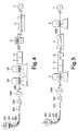
- a plurality of roll stands 2A, 2B, etc. can be coupled sequentially in a series, as illustrated in Fig. 4.
- This Figure also illustrates the possibility of placing the pickling bath 5 downstream from the cold-stretching mill 6.
- the cold-stretching mill may also function to de-scale the strip surfaces, therewith possibly eliminating the need for a shot-blasting machine upstream from the pickling bath.
- the cold-stretching mill 6 of Fig. 1-Fig. 4 and the bridle rolls on both sides thereof is replaced by a cold-rolling mill 6'.
- the cold-rolled and pickled strip 100E (as far as the manufacturing of the cold-rolled strip 100E is concerned, see the foregoing description) is passed through the cold rolling mill 6' to obtain a permanent elongation of the strip and therewith a reduction in strip thickness of 2-20%, preferably 3-10%.
- the permanent elongation of the strip also results in a thickness reduction which corresponds to the elongation of the strip.
- a finished strip 100F with desired final thickness can be obtained by adapting the reduction in strip thickness achieved by cold-rolling the strip in the cold-rolling mill 2 to the thickness reduction obtained by cold-rolling the strip in the cold-rolling mill 6, or vice versa, whereafter the strip is coiled onto the recoiler 7.
- the details ofthe line following the strip-casting is concerned, reference is made to Fig. 2 and the foregoing description in connection with Fig. 2.
- the cast strip 100 is passed through a holding furnace 105 which maintains the temperature ofthe cast strip 100 at or raises it to a temperature between 900 and 1200°C suitable for hot-rolling.
- the cast strip is hot-rolled in a hot-rolling mill 106 which works at the same rate as the caster 101.
- the cast and hot-rolled strip 100' is then coiled 104'.
- any stainless steel material can be processed, but in the first place manufacturing of austenitic stainless steel strips are contemplated. Since the method has advantages in terms of economical production as well as in terms of desirable material improvements, it can be employed for mass production of strips of standard grades oftype 304 and 316 and variations thereofbut also for manufacturing of strips of special stainless steels which contain very high contents of nickel and/or molybdenum, e.g. 5-15% molybdenum, or other alloy elements which may cause problems in connection with conventional stainless steel strip manufacturing.
Abstract
Description
- Fig. 1
- illustrates very schematically the principles of the invention according to a first embodiment, including an initial strip casting;
- Fig. 2
- illustrates in more detail the manufacturing line, following the initial strip casting, according to the first embodiment;
- Fig. 3
- illustrates in larger scale and in more detail a cold-stretching mill used in the first embodiment of the method;
- Fig. 4
- schematically illustrates a modification of the first embodiment of the method of the invention;
- Fig. 5
- schematically illustrates the principals of the invention according to a second embodiment, including an initial strip casting;
- Fig. 6
- schematically illustrates the principals of the invention according to a third embodiment, including an initial strip casting and hot rolling operation; and
- Fig. 7
- schematically illustrates the principals of the invention according to a fourth embodiment, which likewise includes an initial strip casting and hot-rolling operation.
Claims (19)
- A method for manufacturing a stainless steel strip, particularly an austenitic stainless steel strip, with desired final thickness and a yield strength of at least 250 N/mm2,
characterized by,continuously casting a stainless steel, particularly an austenitic stainless steel, into a strip having a thickness of at least 1 mm and at maximum 10 mm,cooling said cast strip to room temperature,cold-rolling the cast strip with at least a 10% thickness reduction to a thickness which is at least 2% and at most 20%, preferably at most 10%, greater than the intended final thickness of the finished product,annealing the thus cold-rolled strip at a temperature of between 1,050°C and 1,250°C; andcold-working the strip after said annealing process so as to permanently elongate the strip and therewith reducing its thickness by 2-20%, preferably by 2-10%. - A method according to Claim 1, characterized in that the cold-working subsequent to said annealing treatment is effected by the combination of continuously stretching the strip and bending the strip around rolls as the strip is being stretched.
- A method according to Claim 2, characterized by pressing the strip against said rolls during the strip-stretching operation and curving said strip with a curvature radius smaller than 200 mm, preferably with a radius of at least 20 mm and at most 150 mm.
- A method according to Claim 1, characterized in that the cold-working subsequent to said annealing treatment is effected by cold-rolling the strip.
- A method according to any one of the Claims 1-4, characterized by cold-rolling the cast strip prior to said annealing treatment to achieve a thickness reduction of 10-60%.
- A method according to Claim 4, characterized by cold-rolling the cast strip prior to said annealing treatment to obtain a thickness reduction of 10-30%.
- A method according to any one of the Claims 1-6, characterized by continuously cold-stretching the strip or by cold-rolling the strip after said annealing treatment so as to permanently elongate the strip and therewith reduce its thickness by 3-5%.
- A method according to any of the Claims 1-7, characterized in that the strip is pickled prior to or after said cold-working operation following the annealing treatment.
- A method for manufacturing a stainless steel strip, particularly an austenitic stainless steel strip, with desired final thickness and a yield strength of at least 250 N/mm2
characterized bycontinuously casting a stainless steel, particularly an austenitic stainless steel to obtain an elongated cast product,hot rolling said elongated cast product to the shape of a strip,cooling said hot-rolled strip to room temperature,cold-rolling the hot-rolled strip with at least a 10% thickness reduction to a thickness which is at least 2% and at most 20%, preferably at most 10%, greater than the intended final thickness of the finished product,annealing the thus cold-rolled strip at a temperature between 1,050°C and 1,250°C; andcold-working the strip after said annealing process so as to permanently elongate the strip and therewith reduce its thickness by 2-20%, preferably by 3-10%. - A method according to claim 9, characterized by continuously casting the stainless steel into a strip having a thickness of at least 1 mm and at most 10 mm, and hot rolling said cast strip with at least 5% and at most 50% thickness reduction, suitably at least 10% and suitably most 30% thickness reduction, so as to break down the cast structure of the strip material prior to cooling the hot rolled strip to room temperature.
- A method according to Claim 1 or 2, characterized in that the cold-working subsequent to said annealing treatment is effected by the combination of continuously stretching the strip and at the same time bending the strip around rolls.
- A method according to Claim 11, characterized by pressing the strip against said rolls during the strip-stretching operation and curving said strip with a curvature radius smaller than 200 mm, preferably with a radius of at least 20 mm and at most 150 mm.
- A method according to Claim 9 or 10, characterized in that the cold-working subsequent to said annealing treatment is effected by cold-rolling the strip.
- A method according to any one of the Claims 1-13, characterized by cold-rolling the hot rolled strip prior to said annealing treatment to achieve a thickness reduction of 10-60%.
- A method according to Claim 14, characterized by cold-rolling the hot-rolled strip prior to said annealing treatment to obtain a thickness reduction of 10-30%.
- A method according to any one of the Claims 9-15, characterized by continuously cold-stretching the strip or by cold-rolling the strip after said annealing treatment so as to permanently elongate the strip and therewith reduce its thickness by 3-10%.
- A method according to any of the Claims 9-16, characterized in that the strip is pickled prior to or after said cold-working operation following the annealing treatment.
- A method according to any of the Claims 1-17, characterized in that the stainless steel contains 0,01-0,10% C, 17-27% Cr, 7-30% Ni 0-15% Mo.
- A method according to claim 18, characterized in that the steel contains 5-15% Mo.
Applications Claiming Priority (2)
| Application Number | Priority Date | Filing Date | Title |
|---|---|---|---|
| SE9603764 | 1996-10-15 | ||
| SE9603764A SE508892C2 (en) | 1996-10-15 | 1996-10-15 | Process for making a stainless steel strip |
Publications (2)
| Publication Number | Publication Date |
|---|---|
| EP0837147A2 true EP0837147A2 (en) | 1998-04-22 |
| EP0837147A3 EP0837147A3 (en) | 1998-12-09 |
Family
ID=20404249
Family Applications (1)
| Application Number | Title | Priority Date | Filing Date |
|---|---|---|---|
| EP97203013A Withdrawn EP0837147A3 (en) | 1996-10-15 | 1997-10-01 | A method for manufacturing a stainless steel strip |
Country Status (8)
| Country | Link |
|---|---|
| EP (1) | EP0837147A3 (en) |
| JP (1) | JPH10121133A (en) |
| KR (1) | KR19980032838A (en) |
| CN (1) | CN1182801A (en) |
| BR (1) | BR9708117A (en) |
| CA (1) | CA2218154A1 (en) |
| SE (1) | SE508892C2 (en) |
| ZA (1) | ZA979197B (en) |
Cited By (6)
| Publication number | Priority date | Publication date | Assignee | Title |
|---|---|---|---|---|
| WO2000037189A1 (en) * | 1998-12-18 | 2000-06-29 | Avesta Sheffield Aktiebolag (Publ) | Method for manufacturing of strips and rolling mill line |
| WO2000037190A1 (en) * | 1998-12-18 | 2000-06-29 | Avesta Sheffield Aktiebolag (Publ) | Method for manufacturing of strips of stainless steel and integrated rolling mill line |
| EP1157138A1 (en) * | 1999-01-12 | 2001-11-28 | Castrip, LLC | Cold rolled steel |
| EP2157195A1 (en) * | 2008-08-14 | 2010-02-24 | Yieh United Steel Corp. | Method of producing thin steel sheet |
| EP3296032A1 (en) * | 2016-09-19 | 2018-03-21 | Yieh United Steel Corp. | Duplex cold rolling line |
| US20220177989A1 (en) * | 2019-01-28 | 2022-06-09 | Outokumpu Oyj | Method for manufacturing of stainless steel strips |
Families Citing this family (6)
| Publication number | Priority date | Publication date | Assignee | Title |
|---|---|---|---|---|
| KR100498069B1 (en) * | 2000-12-21 | 2005-07-01 | 주식회사 포스코 | Method for producing high strength stainless steel in strip casting & in-line rolling apparatus |
| AU2006336816B2 (en) * | 2006-01-26 | 2011-09-15 | Giovanni Arvedi | Strip of hot rolled micro-alloyed steel for obtaining finished pieces by cold pressing and shearing |
| CN101845605B (en) * | 2009-03-24 | 2013-01-02 | 宝山钢铁股份有限公司 | Austenitic stainless steel plate with excellent strength at medium and low temperature and manufacturing method thereof |
| CN105080968B (en) * | 2015-05-19 | 2017-10-27 | 浙江青山钢铁有限公司 | A kind of continuous casting billet milling method of super-duplex stainless steel |
| CN107030264B (en) * | 2017-04-27 | 2019-04-26 | 酒泉钢铁(集团)有限责任公司 | A kind of super austenitic stainless steel double roll strip casting rolling production process |
| CN109848212B (en) * | 2019-03-13 | 2020-08-28 | 山西太钢不锈钢股份有限公司 | Stainless steel strip and rolling method thereof |
Citations (5)
| Publication number | Priority date | Publication date | Assignee | Title |
|---|---|---|---|---|
| US3388011A (en) * | 1965-10-08 | 1968-06-11 | Atomic Energy Commission Usa | Process for the production of high strength steels |
| EP0387786A2 (en) * | 1989-03-14 | 1990-09-19 | Nippon Steel Corporation | Process for producing cold-rolled strip or sheet of austenitic stainless steel |
| WO1993019211A1 (en) * | 1990-09-21 | 1993-09-30 | Avesta Sheffield Aktiebolag | Method for continuous recrystallization annealing of a steel strip |
| EP0664340A2 (en) * | 1994-01-11 | 1995-07-26 | J&L Specialty Steel, Inc. | Continuous method for producing final gauge stainless steel product |
| EP0738781A1 (en) * | 1995-04-21 | 1996-10-23 | Avesta Sheffield Aktiebolag | Process for producing strips of stainless steel |
-
1996
- 1996-10-15 SE SE9603764A patent/SE508892C2/en not_active IP Right Cessation
-
1997
- 1997-10-01 EP EP97203013A patent/EP0837147A3/en not_active Withdrawn
- 1997-10-14 CA CA002218154A patent/CA2218154A1/en not_active Abandoned
- 1997-10-14 ZA ZA9709197A patent/ZA979197B/en unknown
- 1997-10-14 BR BR9708117-5A patent/BR9708117A/en not_active Application Discontinuation
- 1997-10-15 JP JP9281670A patent/JPH10121133A/en active Pending
- 1997-10-15 CN CN97119024A patent/CN1182801A/en active Pending
- 1997-10-15 KR KR1019970052684A patent/KR19980032838A/en not_active Application Discontinuation
Patent Citations (5)
| Publication number | Priority date | Publication date | Assignee | Title |
|---|---|---|---|---|
| US3388011A (en) * | 1965-10-08 | 1968-06-11 | Atomic Energy Commission Usa | Process for the production of high strength steels |
| EP0387786A2 (en) * | 1989-03-14 | 1990-09-19 | Nippon Steel Corporation | Process for producing cold-rolled strip or sheet of austenitic stainless steel |
| WO1993019211A1 (en) * | 1990-09-21 | 1993-09-30 | Avesta Sheffield Aktiebolag | Method for continuous recrystallization annealing of a steel strip |
| EP0664340A2 (en) * | 1994-01-11 | 1995-07-26 | J&L Specialty Steel, Inc. | Continuous method for producing final gauge stainless steel product |
| EP0738781A1 (en) * | 1995-04-21 | 1996-10-23 | Avesta Sheffield Aktiebolag | Process for producing strips of stainless steel |
Cited By (12)
| Publication number | Priority date | Publication date | Assignee | Title |
|---|---|---|---|---|
| WO2000037189A1 (en) * | 1998-12-18 | 2000-06-29 | Avesta Sheffield Aktiebolag (Publ) | Method for manufacturing of strips and rolling mill line |
| WO2000037190A1 (en) * | 1998-12-18 | 2000-06-29 | Avesta Sheffield Aktiebolag (Publ) | Method for manufacturing of strips of stainless steel and integrated rolling mill line |
| US6537398B1 (en) | 1998-12-18 | 2003-03-25 | Avestapolarit Ab (Publ) | Method for manufacturing of strips of stainless steel and integrated rolling mill line |
| US6546771B1 (en) | 1998-12-18 | 2003-04-15 | Avestapolarit Ab | Method for manufacturing of strips and rolling mill line |
| EP1637243A2 (en) | 1998-12-18 | 2006-03-22 | Outokumpu Stainless AB | Method for manufacturing of stainless steel strips and rolling mill line |
| EP1637243A3 (en) * | 1998-12-18 | 2006-08-09 | Outokumpu Stainless AB | Method for manufacturing of stainless steel strips and rolling mill line |
| EP1157138A1 (en) * | 1999-01-12 | 2001-11-28 | Castrip, LLC | Cold rolled steel |
| EP1157138A4 (en) * | 1999-01-12 | 2005-08-31 | Castrip Llc | Cold rolled steel |
| EP2157195A1 (en) * | 2008-08-14 | 2010-02-24 | Yieh United Steel Corp. | Method of producing thin steel sheet |
| EP3296032A1 (en) * | 2016-09-19 | 2018-03-21 | Yieh United Steel Corp. | Duplex cold rolling line |
| CN107838193A (en) * | 2016-09-19 | 2018-03-27 | 烨联钢铁股份有限公司 | Combined type cold rolling line |
| US20220177989A1 (en) * | 2019-01-28 | 2022-06-09 | Outokumpu Oyj | Method for manufacturing of stainless steel strips |
Also Published As
| Publication number | Publication date |
|---|---|
| EP0837147A3 (en) | 1998-12-09 |
| CN1182801A (en) | 1998-05-27 |
| CA2218154A1 (en) | 1998-04-15 |
| SE9603764L (en) | 1998-04-16 |
| ZA979197B (en) | 1998-05-11 |
| JPH10121133A (en) | 1998-05-12 |
| MX9707907A (en) | 1998-08-30 |
| BR9708117A (en) | 1999-09-14 |
| SE508892C2 (en) | 1998-11-16 |
| SE9603764D0 (en) | 1996-10-15 |
| KR19980032838A (en) | 1998-07-25 |
Similar Documents
| Publication | Publication Date | Title |
|---|---|---|
| RU2163934C2 (en) | Method of producing hot-rolled steel strip and device for its embodiment | |
| CA1268402A (en) | Method of producing thin steel sheets having an improved processability | |
| JP4677097B2 (en) | Production method and production equipment for endless production of hot rolled sheet metal products | |
| JP2002504434A (en) | Equipment for producing cold rolled stainless steel strip | |
| JPH0364202B2 (en) | ||
| EP0837147A2 (en) | A method for manufacturing a stainless steel strip | |
| CA2139522C (en) | Continuous method for producing final gauge stainless steel product | |
| EP1637243B1 (en) | Method for manufacturing of stainless steel strips | |
| AU738658B2 (en) | Super thin strip hot rolling | |
| EP0738781B1 (en) | Process for producing strips of stainless steel | |
| US20010037667A1 (en) | Cold rolling method and installtion | |
| US20220177989A1 (en) | Method for manufacturing of stainless steel strips | |
| ZA200500458B (en) | Method and device for the continuous production of metallic strips | |
| US5689991A (en) | Process and device for producing hot-rolled steel strip | |
| US6089063A (en) | Method of and apparatus for producing rolled or cast metal strip with descaled surfaces | |
| JPH06320203A (en) | Continuous casting/hot rolling equipment | |
| CA2236440C (en) | Method for steckel mill operation | |
| MXPA97007907A (en) | Method for manufacturing stainless steel bands | |
| JPH0780508A (en) | Casting/hot rolling continuing equipment | |
| JPH0156126B2 (en) | ||
| RU27826U1 (en) | TECHNOLOGICAL LINE FOR PRODUCING COLD-ROLLED SHEET METAL | |
| Colás et al. | Design of Microstructures and Properties of Steel by Hot and Cold Rolling | |
| JP2003080301A (en) | Equipment and method for continuously annealing and pickling stainless steel plate |
Legal Events
| Date | Code | Title | Description |
|---|---|---|---|
| PUAI | Public reference made under article 153(3) epc to a published international application that has entered the european phase |
Free format text: ORIGINAL CODE: 0009012 |
|
| AK | Designated contracting states |
Kind code of ref document: A2 Designated state(s): AT BE CH DE DK ES FI FR GB GR IE IT LI LU MC NL PT SE |
|
| AX | Request for extension of the european patent |
Free format text: AL;LT;LV;RO;SI |
|
| PUAL | Search report despatched |
Free format text: ORIGINAL CODE: 0009013 |
|
| AK | Designated contracting states |
Kind code of ref document: A3 Designated state(s): AT BE CH DE DK ES FI FR GB GR IE IT LI LU MC NL PT SE |
|
| AX | Request for extension of the european patent |
Free format text: AL;LT;LV;RO;SI |
|
| AKX | Designation fees paid | ||
| STAA | Information on the status of an ep patent application or granted ep patent |
Free format text: STATUS: THE APPLICATION IS DEEMED TO BE WITHDRAWN |
|
| 18D | Application deemed to be withdrawn |
Effective date: 19990610 |
|
| REG | Reference to a national code |
Ref country code: DE Ref legal event code: 8566 |