EP0836900B1 - Method of supplying sand to blow head of blow type molding machine - Google Patents
Method of supplying sand to blow head of blow type molding machine Download PDFInfo
- Publication number
- EP0836900B1 EP0836900B1 EP97914553A EP97914553A EP0836900B1 EP 0836900 B1 EP0836900 B1 EP 0836900B1 EP 97914553 A EP97914553 A EP 97914553A EP 97914553 A EP97914553 A EP 97914553A EP 0836900 B1 EP0836900 B1 EP 0836900B1
- Authority
- EP
- European Patent Office
- Prior art keywords
- blow
- head
- molding sand
- port
- blow head
- Prior art date
- Legal status (The legal status is an assumption and is not a legal conclusion. Google has not performed a legal analysis and makes no representation as to the accuracy of the status listed.)
- Expired - Lifetime
Links
- 238000000465 moulding Methods 0.000 title claims description 8
- 238000000034 method Methods 0.000 title claims description 6
- 239000004576 sand Substances 0.000 title description 2
- 239000003110 molding sand Substances 0.000 claims description 21
- 238000007664 blowing Methods 0.000 claims description 3
Images

Classifications
-
- B—PERFORMING OPERATIONS; TRANSPORTING
- B22—CASTING; POWDER METALLURGY
- B22C—FOUNDRY MOULDING
- B22C15/00—Moulding machines characterised by the compacting mechanism; Accessories therefor
- B22C15/23—Compacting by gas pressure or vacuum
- B22C15/24—Compacting by gas pressure or vacuum involving blowing devices in which the mould material is supplied in the form of loose particles
Definitions
- This invention relates to a method of blow charging molding sand by means of compressed air into a blow head of a blow type molding machine.
- This invention was created to resolve this drawback. Its purpose is to provide a method of supplying molding sand into a blow head wherein the molding sand which flows out of a blow-off port is prevented from being scattered when it is supplied to the blow head.
- the method of the present invention of blow charging molding sand from a blow-off port of a blow head of a blow type molding machine into a blow-in port of a device that defines a mold space comprising the steps of (a) connecting the blow-off port of the blow head to the blow-in port of said device that defines the mold space, and (b) blowing molding sand contained in the blow head into the device through the blow-off and blow-in ports, after step (a) the molding sand is introduced into the blow head, so that the device that defines the mold space can receive a part of the molding sand which flows out of the blow-off port of the blow head when the molding sand is supplied into the blow head.
- the part of the molding sand flowing out of the blow-off port is not scattered in the environment.
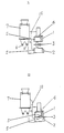
- FIGs. 1 - 4 are explanatory drawings to show the steps of the present invention using a molding machine suitable to execute this invention.
- a match plate 3 is introduced between an upper flask 1 and a lower flask 2. Then, as shown in Fig. 2, the upper flask 1, the match plate 3, and an upper squeeze plate 4, are lowered to superimpose the match plate 3 and upper flask 1 on the lower flask 2. Then, as shown in Fig.
- the superimposed upper and lower flasks 1, 2 and match plate 3 are rotated by a rotary device 10 through 90° about a horizontal axis of rotation to connect two blow-in ports 5, 5 of the upper and lower flasks 1, 2 with blow-off ports 6, 6 of a blow head 7, and a lower squeeze plate 8 is inserted just a little into an end opening of the lower flask 2.
- a device that defines a mold space comprising the upper and lower flasks 1, 2, match plate 3, and upper and lower squeeze plates 4, 8, defines a mold space 9.
- a predetermined amount of molding sand S is then supplied into the empty blow head 7. Although a part of the molding sand S flows out of the blow-off ports 6, 6 of the blow head 7, it enters the device (i.e., mold space 9) through the blow-in ports 5, 5. Thus it is not scattered outside the blow-off ports. Compressed air is then supplied into the blow head 7 by a known means (not shown) to blow the molding sand in the blow head 7 into the mold space, and the molding sand in the mold space is then squeezed by the upper and lower squeeze plates 4, 8. Thus a cope and a drag are produced by this molding machine in the normal molding operation.
Landscapes
- Engineering & Computer Science (AREA)
- Mechanical Engineering (AREA)
- Casting Devices For Molds (AREA)
Description
Claims (2)
- A method of blowing molding sand from a blow-off port of a blow head of a blow type molding machine into a blow-in port of a device that defines a mold space, comprising the steps of (a) connecting the blow-off port of the blow head to the blow-in port of said device that defines the mold space, and (b) blowing molding sand contained in the blow head into the device through the blow-off and blow-in ports,
characterized in that after step (a) the molding sand is introduced into the blow head. - The method of claim 1, characterized in that the device is rotated about a horizontal axis such that the blow-in port of the device engages with the blow-off port of the blow head.
Applications Claiming Priority (4)
| Application Number | Priority Date | Filing Date | Title |
|---|---|---|---|
| JP8110495A JPH09271897A (en) | 1996-04-05 | 1996-04-05 | Method for supplying sand into blow head in blow-in type molding machine |
| JP11049596 | 1996-04-05 | ||
| JP110495/96 | 1996-04-05 | ||
| PCT/JP1997/001056 WO1997037790A1 (en) | 1996-04-05 | 1997-03-27 | Method of supplying sand to blow head of blow type molding machine |
Publications (4)
| Publication Number | Publication Date |
|---|---|
| EP0836900A1 EP0836900A1 (en) | 1998-04-22 |
| EP0836900A4 EP0836900A4 (en) | 1998-05-20 |
| EP0836900B1 true EP0836900B1 (en) | 2001-12-12 |
| EP0836900B2 EP0836900B2 (en) | 2007-11-14 |
Family
ID=14537211
Family Applications (1)
| Application Number | Title | Priority Date | Filing Date |
|---|---|---|---|
| EP97914553A Expired - Lifetime EP0836900B2 (en) | 1996-04-05 | 1997-03-27 | Method of supplying sand to blow head of blow type molding machine |
Country Status (6)
| Country | Link |
|---|---|
| US (1) | US5927372A (en) |
| EP (1) | EP0836900B2 (en) |
| JP (1) | JPH09271897A (en) |
| CN (1) | CN1161198C (en) |
| DE (1) | DE69709020T3 (en) |
| WO (1) | WO1997037790A1 (en) |
Families Citing this family (8)
| Publication number | Priority date | Publication date | Assignee | Title |
|---|---|---|---|---|
| US8033316B2 (en) * | 2005-06-07 | 2011-10-11 | Sintokogio, Ltd. | Flask unit and cope-and-drag molding machine and line |
| BRPI0612037B1 (en) * | 2005-06-13 | 2015-08-04 | Sintokogio Ltd | Molding apparatus without molding box for upper and lower mold |
| EP1897635B1 (en) | 2005-06-13 | 2015-04-22 | Sintokogio, Ltd. | A method for making flaskless upper and lower molds, an apparatus therefor, and a method for placing a core. |
| DE102007026537A1 (en) | 2006-12-18 | 2007-11-29 | Sintokogio, Ltd., Nagoya | Molding machine for molding a pair of box-less casting molds comprises molding boxes, an exchangeable model plate, a device for moving the boxes, pressing parts, a support device and adjusting drives for moving the pressing parts |
| US7762307B2 (en) * | 2007-01-16 | 2010-07-27 | Sintokogio Ltd. | Sand-introducing device using air, and method and apparatus for producing a mold |
| US7681624B2 (en) * | 2007-05-25 | 2010-03-23 | Sintokogio, Ltd. | Flaskless molding machine |
| JP6468243B2 (en) | 2016-05-17 | 2019-02-13 | 新東工業株式会社 | Frame making machine |
| JP6468242B2 (en) | 2016-05-17 | 2019-02-13 | 新東工業株式会社 | Frame making machine |
Family Cites Families (12)
| Publication number | Priority date | Publication date | Assignee | Title |
|---|---|---|---|---|
| US3089207A (en) * | 1959-04-09 | 1963-05-14 | Osborn Mfg Co | Blow-squeeze molding machine |
| US3730250A (en) * | 1969-01-09 | 1973-05-01 | H Fellows | Method of making a sand mold |
| JPS5213425A (en) * | 1975-07-23 | 1977-02-01 | Sintokogio Ltd | Method of forming mold |
| JPS5220928A (en) * | 1975-08-12 | 1977-02-17 | Sintokogio Ltd | Prow squeeze machine |
| JPS5317083A (en) * | 1976-07-30 | 1978-02-16 | Kanematsu Semi Conductor | Semiconductor device |
| JPS5317084A (en) * | 1976-07-30 | 1978-02-16 | Hitachi Ltd | Buried hetero type semiconductor laser device |
| JPS56168935A (en) † | 1980-05-27 | 1981-12-25 | Sintokogio Ltd | Method and device for blowing of casting sand |
| JP2772854B2 (en) * | 1990-06-29 | 1998-07-09 | 新東工業株式会社 | Casting sand filling method |
| JP2772859B2 (en) * | 1990-07-27 | 1998-07-09 | 新東工業株式会社 | Frameless mold making machine |
| DE4033887C2 (en) * | 1990-10-25 | 1994-07-28 | Hottinger Adolf Masch | Device and method for producing molded parts for foundry purposes |
| JPH05277635A (en) * | 1992-03-31 | 1993-10-26 | Isuzu Motors Ltd | Method for removing sand in cold box molding machine |
| JP3121180B2 (en) * | 1993-07-02 | 2000-12-25 | 新東工業株式会社 | Horizontal cutting frame mold making equipment |
-
1996
- 1996-04-05 JP JP8110495A patent/JPH09271897A/en active Pending
-
1997
- 1997-03-27 DE DE69709020T patent/DE69709020T3/en not_active Expired - Lifetime
- 1997-03-27 CN CNB971903212A patent/CN1161198C/en not_active Expired - Lifetime
- 1997-03-27 EP EP97914553A patent/EP0836900B2/en not_active Expired - Lifetime
- 1997-03-27 US US08/973,330 patent/US5927372A/en not_active Expired - Lifetime
- 1997-03-27 WO PCT/JP1997/001056 patent/WO1997037790A1/en not_active Ceased
Also Published As
| Publication number | Publication date |
|---|---|
| DE69709020T2 (en) | 2002-05-02 |
| CN1188435A (en) | 1998-07-22 |
| WO1997037790A1 (en) | 1997-10-16 |
| US5927372A (en) | 1999-07-27 |
| DE69709020T3 (en) | 2008-03-13 |
| EP0836900A4 (en) | 1998-05-20 |
| CN1161198C (en) | 2004-08-11 |
| DE69709020D1 (en) | 2002-01-24 |
| EP0836900B2 (en) | 2007-11-14 |
| JPH09271897A (en) | 1997-10-21 |
| EP0836900A1 (en) | 1998-04-22 |
Similar Documents
| Publication | Publication Date | Title |
|---|---|---|
| EP0836900B2 (en) | Method of supplying sand to blow head of blow type molding machine | |
| CZ20011265A3 (en) | Rotary casting process and apparatus for making the same | |
| CN109641267A (en) | Casting system | |
| US4791974A (en) | Method and an apparatus for producing shaped bodies from particulate material | |
| US5915451A (en) | Casting core fabrication apparatus | |
| CN105921626B (en) | A kind of more moving mold devices and its manufacture method | |
| JPH05123827A (en) | Device and method for molding a mold part for casting | |
| US5069268A (en) | Basin former for a matchplate molding machine | |
| CN208067247U (en) | Sand integrates cleaning equipment more than a kind of whole core of 3D printing | |
| CN208162551U (en) | Aluminum casting mixes movement system with sand | |
| CN208512502U (en) | A kind of diamond synthesizing powder moulding mold | |
| CN108339940A (en) | Running gate system and casting mold for manufacturing compresser cylinder casting | |
| GB1404052A (en) | Methods of operating automatic mould part producing apparatus and apparatuses for carrying out these methods | |
| CN219909999U (en) | Small-sized fine stone concrete conveying pump | |
| CN2370980Y (en) | Screw vibration used sand regenerator | |
| KR100921805B1 (en) | Molding Vent Processing Equipment | |
| CN211660423U (en) | Casting solvent filtering device | |
| JPH0466253A (en) | Side die clamping vertical casting type die casting machine | |
| CN205851801U (en) | The plaster core manufacturing system that a kind of large-scale pump vane casting uses | |
| JP3518969B2 (en) | Mold core molding method and molding apparatus | |
| JPH08132180A (en) | Mold making method and apparatus | |
| JPS62101361A (en) | Applying method for release agent for rotor die casting | |
| JPS5534608A (en) | Draw-off machine for residual cast iron from mixed cast iron separating tank | |
| CN208214251U (en) | A kind of molten iron level detection and automatic modulus system based on laser identification | |
| KR0120765Y1 (en) | A die casting machine |
Legal Events
| Date | Code | Title | Description |
|---|---|---|---|
| PUAI | Public reference made under article 153(3) epc to a published international application that has entered the european phase |
Free format text: ORIGINAL CODE: 0009012 |
|
| 17P | Request for examination filed |
Effective date: 19971205 |
|
| AK | Designated contracting states |
Kind code of ref document: A1 Designated state(s): DE FR GB |
|
| RHK1 | Main classification (correction) |
Ipc: B22C 15/28 |
|
| A4 | Supplementary search report drawn up and despatched | ||
| AK | Designated contracting states |
Kind code of ref document: A4 Designated state(s): DE FR GB |
|
| 17Q | First examination report despatched |
Effective date: 19991124 |
|
| GRAG | Despatch of communication of intention to grant |
Free format text: ORIGINAL CODE: EPIDOS AGRA |
|
| GRAG | Despatch of communication of intention to grant |
Free format text: ORIGINAL CODE: EPIDOS AGRA |
|
| GRAH | Despatch of communication of intention to grant a patent |
Free format text: ORIGINAL CODE: EPIDOS IGRA |
|
| GRAG | Despatch of communication of intention to grant |
Free format text: ORIGINAL CODE: EPIDOS AGRA |
|
| GRAH | Despatch of communication of intention to grant a patent |
Free format text: ORIGINAL CODE: EPIDOS IGRA |
|
| GRAH | Despatch of communication of intention to grant a patent |
Free format text: ORIGINAL CODE: EPIDOS IGRA |
|
| GRAA | (expected) grant |
Free format text: ORIGINAL CODE: 0009210 |
|
| AK | Designated contracting states |
Kind code of ref document: B1 Designated state(s): DE FR GB |
|
| REG | Reference to a national code |
Ref country code: GB Ref legal event code: IF02 |
|
| REF | Corresponds to: |
Ref document number: 69709020 Country of ref document: DE Date of ref document: 20020124 |
|
| ET | Fr: translation filed | ||
| PLBQ | Unpublished change to opponent data |
Free format text: ORIGINAL CODE: EPIDOS OPPO |
|
| PLBI | Opposition filed |
Free format text: ORIGINAL CODE: 0009260 |
|
| PLBF | Reply of patent proprietor to notice(s) of opposition |
Free format text: ORIGINAL CODE: EPIDOS OBSO |
|
| 26 | Opposition filed |
Opponent name: DISA INDUSTRIES A/S Effective date: 20020911 |
|
| PLBF | Reply of patent proprietor to notice(s) of opposition |
Free format text: ORIGINAL CODE: EPIDOS OBSO |
|
| PLBF | Reply of patent proprietor to notice(s) of opposition |
Free format text: ORIGINAL CODE: EPIDOS OBSO |
|
| RDAF | Communication despatched that patent is revoked |
Free format text: ORIGINAL CODE: EPIDOSNREV1 |
|
| APBP | Date of receipt of notice of appeal recorded |
Free format text: ORIGINAL CODE: EPIDOSNNOA2O |
|
| APBM | Appeal reference recorded |
Free format text: ORIGINAL CODE: EPIDOSNREFNO |
|
| APBQ | Date of receipt of statement of grounds of appeal recorded |
Free format text: ORIGINAL CODE: EPIDOSNNOA3O |
|
| APAH | Appeal reference modified |
Free format text: ORIGINAL CODE: EPIDOSCREFNO |
|
| APBU | Appeal procedure closed |
Free format text: ORIGINAL CODE: EPIDOSNNOA9O |
|
| PUAH | Patent maintained in amended form |
Free format text: ORIGINAL CODE: 0009272 |
|
| STAA | Information on the status of an ep patent application or granted ep patent |
Free format text: STATUS: PATENT MAINTAINED AS AMENDED |
|
| 27A | Patent maintained in amended form |
Effective date: 20071114 |
|
| AK | Designated contracting states |
Kind code of ref document: B2 Designated state(s): DE FR GB |
|
| ET3 | Fr: translation filed ** decision concerning opposition | ||
| REG | Reference to a national code |
Ref country code: FR Ref legal event code: PLFP Year of fee payment: 20 |
|
| PGFP | Annual fee paid to national office [announced via postgrant information from national office to epo] |
Ref country code: GB Payment date: 20160329 Year of fee payment: 20 |
|
| PGFP | Annual fee paid to national office [announced via postgrant information from national office to epo] |
Ref country code: DE Payment date: 20160329 Year of fee payment: 20 |
|
| PGFP | Annual fee paid to national office [announced via postgrant information from national office to epo] |
Ref country code: FR Payment date: 20160329 Year of fee payment: 20 |
|
| REG | Reference to a national code |
Ref country code: DE Ref legal event code: R071 Ref document number: 69709020 Country of ref document: DE |
|
| REG | Reference to a national code |
Ref country code: GB Ref legal event code: PE20 Expiry date: 20170326 |
|
| PG25 | Lapsed in a contracting state [announced via postgrant information from national office to epo] |
Ref country code: GB Free format text: LAPSE BECAUSE OF EXPIRATION OF PROTECTION Effective date: 20170326 |