EP0836711B1 - Verfahren und vorrichtung zur unterdrückung redundanten schreibens - Google Patents
Verfahren und vorrichtung zur unterdrückung redundanten schreibens Download PDFInfo
- Publication number
- EP0836711B1 EP0836711B1 EP96921701A EP96921701A EP0836711B1 EP 0836711 B1 EP0836711 B1 EP 0836711B1 EP 96921701 A EP96921701 A EP 96921701A EP 96921701 A EP96921701 A EP 96921701A EP 0836711 B1 EP0836711 B1 EP 0836711B1
- Authority
- EP
- European Patent Office
- Prior art keywords
- size
- write
- region
- client
- server
- Prior art date
- Legal status (The legal status is an assumption and is not a legal conclusion. Google has not performed a legal analysis and makes no representation as to the accuracy of the status listed.)
- Expired - Lifetime
Links
Images




Classifications
-
- G—PHYSICS
- G06—COMPUTING OR CALCULATING; COUNTING
- G06F—ELECTRIC DIGITAL DATA PROCESSING
- G06F12/00—Accessing, addressing or allocating within memory systems or architectures
- G06F12/02—Addressing or allocation; Relocation
- G06F12/08—Addressing or allocation; Relocation in hierarchically structured memory systems, e.g. virtual memory systems
- G06F12/0802—Addressing of a memory level in which the access to the desired data or data block requires associative addressing means, e.g. caches
- G06F12/0804—Addressing of a memory level in which the access to the desired data or data block requires associative addressing means, e.g. caches with main memory updating
-
- G—PHYSICS
- G06—COMPUTING OR CALCULATING; COUNTING
- G06F—ELECTRIC DIGITAL DATA PROCESSING
- G06F11/00—Error detection; Error correction; Monitoring
- G06F11/07—Responding to the occurrence of a fault, e.g. fault tolerance
- G06F11/14—Error detection or correction of the data by redundancy in operations
- G06F11/1402—Saving, restoring, recovering or retrying
- G06F11/1415—Saving, restoring, recovering or retrying at system level
- G06F11/1435—Saving, restoring, recovering or retrying at system level using file system or storage system metadata
-
- G—PHYSICS
- G06—COMPUTING OR CALCULATING; COUNTING
- G06F—ELECTRIC DIGITAL DATA PROCESSING
- G06F12/00—Accessing, addressing or allocating within memory systems or architectures
- G06F12/02—Addressing or allocation; Relocation
- G06F12/08—Addressing or allocation; Relocation in hierarchically structured memory systems, e.g. virtual memory systems
- G06F12/0802—Addressing of a memory level in which the access to the desired data or data block requires associative addressing means, e.g. caches
- G06F12/0866—Addressing of a memory level in which the access to the desired data or data block requires associative addressing means, e.g. caches for peripheral storage systems, e.g. disk cache
- G06F12/0868—Data transfer between cache memory and other subsystems, e.g. storage devices or host systems
-
- G—PHYSICS
- G06—COMPUTING OR CALCULATING; COUNTING
- G06F—ELECTRIC DIGITAL DATA PROCESSING
- G06F2212/00—Indexing scheme relating to accessing, addressing or allocation within memory systems or architectures
- G06F2212/15—Use in a specific computing environment
- G06F2212/154—Networked environment
-
- G—PHYSICS
- G06—COMPUTING OR CALCULATING; COUNTING
- G06F—ELECTRIC DIGITAL DATA PROCESSING
- G06F2212/00—Indexing scheme relating to accessing, addressing or allocation within memory systems or architectures
- G06F2212/16—General purpose computing application
- G06F2212/163—Server or database system
Definitions
- the present invention relates to data storage in computer networks, and more specifically to a method and apparatus for combining writes and avoiding redundant writes when flushing cached data across a network.
- the central processor is separated from a non-volatile data storage medium by a bus, network, or other communication channel. For instance, in many networks modified data must be transferred across a network link before it can be written on non-volatile storage such as a hard disk.
- the server is a processing unit dedicated to managing centralized resources, managing data, and sharing resources with the personal computers and workstations, which are referred to as "clients" of the server.
- Cache memory is divided into regions known as “cache blocks.” Blocks that have been written to but not yet copied to non-volatile storage are called “dirty" blocks.
- a drawback of conventional systems is their performance of redundant write operations. In some cases, entire blocks are written across the network even though only a portion of the block was overwritten in cache. Thus, much "clean" data is unnecessarily transferred through one or more communication channels to the server's hard disk. Moreover, conventional systems assume that the data values stored in a cache block are changed when ever data is written to that cache block. In fact, the previously cached values do not always differ from the values written over them. As a result, the same data may be sent through the communication channel twice during consecutive writes, to be stored again at the same location on the server's disk. Such transfers add to network congestion without preserving new data.
- IBM Technical Disclosure Bulletin, Vol, 34, no. 3, pages 266-268, August 1991 discloses a method for using the overhead message costs of network messages to choose between cache coherency strategies in a distributed file system.
- a cost function which reflects file usage patterns is used to choose between a FULL_SYNC mode and a SYNC_WRITE mode on a per-file basis. Each mode assumes more than one node has the file open and at least one of the opens is for writing.
- FULL_SYNC mode no client caches are used; all reads and writes are sent synchronously to the server.
- SYNC_WRITE mode clients are allowed to use local caches for reading but all writes are sent to the server; on receiving a write, the server sends messages to the clients to invalidate their cached data.
- this disclosure is really directed to the question of whether a cache should be used, whilst the present invention is directed toward selecting which cached data to write, in providing ways to avoid redundant writes within a given cache block that have already been sent to the server.
- the present invention provides an apparatus, method and computer-readable medium for selecting cached data to write across a computer network from a client to a server, in accordance with the claims which follow.
- the client includes a client data cache, which may be a conventional cache.
- One method includes the computer-implemented step of determining a write-bridge size, in a manner set forth after use of the write-bridge is described.
- Additional steps locate first and second dirty regions in the client data cache.
- the dirty regions are separated from one another by a clean region of a determinable size.
- the dirty regions may be defined in altemative ways according to the present invention. Under one definition, a byte of cache is dirty if it was overwritten after the most recent flushing of data stored at that location. Under an alternative definition, the byte is dirty only if it has been thus overwritten and if the new data differs in value from the data that was overwritten.
- a write region containing cached data is selected and "flushed" or written across the network from the client to the server.
- the selected write region includes the clean region and both dirty regions when the write-bridge size exceeds the size of the clean region. Otherwise the write region includes one of the dirty regions, and a second write region including the other dirty region is subsequently flushed.
- the write-bridge size may be determined in various ways according to the present invention. For instance, the write-bridge may be set to twice an overhead message size; set to a largest single message size if packet round trip time is excessive; set to a predetermined minimum if throughput is low; set to the minimum of the largest message size and the cache block size; set to the largest message size less the sum of the sizes of two previously located dirty regions; or set to the product of throughput and round trip time.
- the decision whether to combine dirty regions in one write or to send them separately in two writes is based on conditions which involve one or more of the following: the largest single message size, the respective sizes of the dirty regions, the size of the clean region between the dirty regions, the throughput of the communication channel in bytes per second, and the round trip time in seconds.
- the invention tends to limit writes to those that contain only dirty data, redundant writes are reduced or eliminated.
- the invention balances the goals of avoiding network congestion, updating the cache promptly, and utilizing available network bandwidth to reflect the inherent characteristics and current conditions of the cache and the network.
- Figure 1 is a schematic illustration of a computer network.
- Figure 2 is a diagram illustrating embodiments of a client computer and a server computer in the computer network according to the present invention.
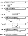
- Figure 3 is a diagram illustrating a cache block containing some text.
- Figure 4 is a diagram illustrating text that will overwrite a portion of the cache block shown in Figure 3.
- Figure 5 is a diagram illustrating the cache block of Figure 3 after entry of the text shown in Figure 4.
- Figure 6 is a diagram illustrating additional text that will overwrite a portion of the cache block shown in Figure 5.
- Figure 7 is a diagram illustrating the cache block of Figure 5 after entry of the text shown in Figure 6 and indicating a gap between two dirty regions.
- Figure 8 is a diagram illustrating the cache block of Figure 7 after a first dirty region is flushed.
- Figure 9 is a diagram illustrating the cache block of Figure 7 after two dirty regions are combined to form one larger dirty region.
- Figure 10 is a diagram illustrating the result of flushing all dirty regions from the cache block of Figure 7.
- the present invention relates to a method and apparatus for removing redundant writes from the operations performed in a computer network.
- One of the many networks suited for use with the present invention is indicated generally at 10 in Figure 1.
- the network 10 includes Novell NetWare® software, version 4.x (NetWare is a registered trademark of Novell, Inc.).
- the illustrated network 10 includes several connected local networks 12.
- Each local network 12 includes a file server 14 connected by signal lines 16 to one or more clients 18 such as personal computers and workstations.
- a printer 20 and an array of disks 22 are also attached to the network 10.
- a particular network 10 is shown, those of skill in the art will recognize that the present invention is also useful in a variety of other networks.
- the server 14 includes a network port 28 which allows the server 14 to read packets from, and write packets to, the signal line 16 that carries packets between the server 14 and the client 18.
- the network port 28 includes hardware and software familiar to those in the art, and the packets are organized, transmitted, and interpreted in a manner that is readily determined by those of skill in the art.
- the server 14 also includes a server memory 30 such as a random access memory ("RAM").
- the server memory 30 is one example of a "data store,” also known as a "computer-readable medium.” Other familiar data stores include, without limitation, magnetic hard disks, magnetic floppy disks, optical disks, CD-ROM disks, and magnetic tape.
- Each such data store includes a substrate such as a magnetic material which is capable of storing data in physical form. According to the present invention, the substrate of the server memory 30 is given a specific physical configuration that causes the server 14 to operate in the manner taught herein.
- a first portion of the server memory 30 stores a server operating system 32.
- the server operating system 32 includes familiar operating system capabilities that are supplemented, modified, and/or replaced in a manner readily determined by those of skill in the art by the redundant write removal capabilities of the present invention.
- a second portion of the server memory 30 stores a server cache 34.
- the server 14 also includes a central processing unit (“CPU") 36 and a non-volatile store 38.
- the non-volatile store 38 includes a controller 40 which is in control signal communication with the CPU 36 and in data transfer communication with the server cache 34.
- the CPU 36 is capable of sending read and write requests to the controller 40.
- the client 18 includes a network port 44, a CPU 46, and a client memory 48.
- Each of the CPUs 36, 46 must be capable of being controlled by software in a manner that makes the computers 14, 18 operate according to the present invention.
- Illustrative embodiments of suitable controlling software written in the C programming language are provided in the '563 application and the '919 application.
- the client memory 48 includes RAM which is configured in three portions to control operation of the client computer 18.
- a first portion of the client memory 48 stores an application program 50 such as a word processors or spreadsheets.
- a second portion of the client memory 48 stores a client operating system 52 which includes familiar operating system capabilities supplemented, modified, and/or replaced by the redundant write removal capabilities of the present invention.
- a third portion of the client memory 48 stores a client cache 54.
- Figures 3 through 10 illustrate operation of the present invention.
- Figure 3 shows a server cache data block 60.
- the present invention is illustrated in reducing write operations from the client 18 to the server 14, the invention may also be used to reduce redundant writes from the server 14 to the client 18 or redundant writes between different clients 18, as in a peer-to-peer network.
- the server cache data block 60 will be referred to hereafter simply as cache block 60.
- the present invention is illustrated using English text in the cache block 60, but the invention may also be used to reduce redundant writes of numeric or other types of data.
- Figure 4 shows a first region 62 of text that will overwrite a portion of the cache block 60 shown in Figure 3.
- the region 62 is aligned in the drawings with the portion of the cache block 60 that will be overwritten.
- the region 62 is typically in a portion of the client memory 48 ( Figure 2) that is allocated to the application 50 or operating system 52 code that generated the data in the region 62.
- FIG. 5 shows the cache block 60 after entry of the textual data in the region 62.
- the overwritten portion of the cache block 60 is defined by two boundaries 64, 66.
- the boundaries may be implemented as pointer or array index variables.
- the boundary 64 is a variable named "DirtyStart”
- the boundary 66 is a variable named "DirtyEnd”.
- DirtyStart can point to the first dirty byte (holding the "p"), to the last clean byte (holding the "m"), or even to some other byte, provided only that the relationship between the value of DirtyStart and the first dirty byte is stable and understood and that suitable measures are taken to accommodate the boundaries of the cache block 60. Similar considerations apply to DirtyEnd.
- Figure 6 shows a second region 68 of text that will overwrite another portion of the cache block 60.
- the remarks made above in connection with clarity of illustration in Figure 4 also apply here.
- Figure 7 shows the cache block 60 after entry of the textual data in the second region 68.
- a gap 70 is thus defined between the two dirty regions 62 and 68.
- the size of the gap 70 is used according to the present invention to determine whether the regions 62 and 68 should be flushed to the server 14 ( Figure 2) separately or together.
- the second region 68 is defined by two boundaries 72, 74. Like the boundaries 64, 66 of the first region 62, the boundaries 72, 74 of the second region 68 may be implemented as pointer or array index variables and may point to the first dirty byte, to the last clean byte, or to some other byte, so long as the relationship between their values and the region 68 is stable and clear.
- the boundary 72 is a variable named "NewDirtyStart" and the boundary 66 is a variable named "NewDirtyEnd".
- Figures 8 and 9 illustrate alternative steps which are taken depending on the size of the gap 70 (Figure 7). If the gap 70 is too large, it is more efficient to flush the regions 62 and 68 separately.
- Figure 8 shows the cache block 60 after the first region 62 ( Figure 7) has been flushed. However, if the gap 70 is small enough, it is more efficient to combine the regions 62 and 68 into one larger dirty region 80 as shown in Figure 9.
- the combined region 80 is defined by a left boundary 82 that coincides with the leftmost boundary 64 of the first region 62 and a right boundary 84 that coincides with the rightmost boundary 74 of the second region 68. Like the other boundaries 64, 66, 72, and 74, the boundaries 82, 84 of the combined region 80 may be implemented in various ways as pointer or array index variables.
- Figure 10 shows the cache block 60 after all dirty regions are flushed. Depending on the size of the gap 70, one flushes the dirty regions 62 and 68 of Figure 7 one at a time in separate write operations as illustrated in Figure 8, or else one combines the two regions 62, 68 with the gap 70 to form a larger region 80 which is flushed in a single write operation.
- Figures 11-13 further illustrate methods of the present invention generally, as well as particular steps for evaluating the size of a gap such as the gap 70 to determine whether dirty regions should be combined for one flush operation or flushed separately.
- the method shown in Figure 11 includes a bridge size-determining step 90. During the step 90, the size of a write-bridge is determined. The write-bridge is so named because the decision between flushing the two dirty regions 62, 68 separately and flushing the single combined dirty region 80 depends on whether the value determined during this step 90 bridges the gap 70. Steps for determining the write-bridge size, which are shown in Figure 12, are discussed below.
- Figure 11 also shows a first region-locating step 92 and a second region-locating step 94.
- the step 92 includes locating the boundaries of a first dirty region such as the region 62 and setting boundary variables appropriately, such as in Figure 5.
- the step 94 similarly includes locating the boundaries of a second dirty region such as the region 68 and setting boundary variables appropriately, such as in Figure 8.
- the steps 92 and 94 are performed in the opposite order.
- a gap size-determining step 96 the size of the clean region located between the dirty regions thus located is determined. This determination depends on the implementation used to set values for the boundary variables, as discussed in connection with Figures 5 and 7, but consists essentially of subtracting the value indicated by boundary 66 from that indicated by boundary 72.
- the write-bridge size determined during step 90 is compared with the gap size determined during step 96. If the write-bridge is larger, it spans the gap and the regions are combined with the intervening clean region, as illustrated in Figure 9, and then flushed during a combining step 100 and a flushing step 102. Otherwise, the two regions are flushed separately during two steps 104, 106, and the intervening clean region is not flushed.
- Figure 8 shows an example of the cache block 60 after the first flushing step 104 and before the second flushing step 106.
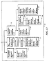
- One method includes an overhead message size-determining step 110 followed by a magnifying bridge size setting step 112.
- the step 110 determines an overhead message size for the network 10 ( Figure 1).
- the overhead message size is the total size of all headers in the various protocols or network layers used to build a message.
- the write-bridge is set to the overhead message size magnified by a factor.
- the presently preferred factor is 2.0, but other suitable factors will be readily determined by those of skill in the art.
- An alternative method for determining the write-bridge size includes a threshold-setting step 114, a throughput-measuring step 116, a comparing step 118, and a test-and-set step 120.
- Suitable throughput thresholds representing a lightly loaded network can be readily determined by those of skill in the art during the step 114 by looking at past performance of the network 10 and by iteratively repeating steps 90-106 and 114-120 with different threshold values.
- the throughput-measuring step 116 may be omitted if network throughput is already know. Otherwise, throughput is measured by timing the transmission and receipt of a small message that is also echoed back. This measured time is divided into the difference in size of the two messages to produce a value representing throughput in bytes per second.
- the data in the echo message should be sufficiently random that network routers to prevent network routers from compressing the message, as that will give a false measure of the actual throughput.
- the result of the threshold-setting step 114 is compared to the measured throughput during the comparing step 118 and acted upon during the test-and-set step 120. If the measured throughput is below the threshold, the write-bridge size is set to a predefined minimum value. This has the effect of favoring two separate region flushes over a single combined region flush because the write-bridge will tend not to span the gap 70 ( Figure 7). This increases the number of write operations but reduces the transfer of data that has already been flushed.
- the write-bridge size remains unchanged.
- the method of steps 114-120 can thus be used in combination with the method of steps 110-112. Indeed, the several methods illustrated in Figure 12 are not mutually exclusive but may be combined for use at different times and/or in different communication channels within the same network 10.
- LMS determining step 122 each include a LMS determining step 122.
- One alternative also includes a LMS-based setting step 124.
- a second alternative also includes a cache block sizing step 126 and a compare-and-set step 128.
- a third alternative also includes a reduced LMS-based setting step 130.
- the LMS, or largest message size, of the network 10 (Figure 1) is determined during the step 122 by considering a combination of the transport protocol and the network and datalink layers of the network 10, as viewed according to the OSI (Open Systems Interconnection) Reference Model.
- the LMS represents the actual amount of data that can be sent with a message and does not include the headers prepended or appended by the various protocols and layers. To put it another way, the LMS represents the amount of data that can be sent without waiting for an acknowledgement response packet.
- the cache block size is typically set by the network operating system 52 ( Figure 2) but may be configurable in some embodiments according to the present invention.
- the cache block size is normally a power of two so that calculations using the size can be performed using shift instructions instead of more expensive general-purpose multiply and divide instructions.
- Cache block sizes are optimal when their size is an integer multiple of the size of the physical medium's controller block size. For instance, disk sectors are often 512 bytes, so one suitable cache block size is eight times that, or 4096 byes.
- the smaller the cache block the greater the chance of removing redundant write data because the clean region between two dirty regions is more likely to fill a cache block.
- the larger the cache block the less overhead is needed for large sets of data.
- Figure 13 illustrates an alternative method of the present invention.
- the alternative method comprises the LMS determining step 122 ( Figure 12), the region-locating steps 92 and 94 ( Figure 11) and the gap size-determining step 96 ( Figure 11).
- a throughput-determining step 140 determines the current channel throughput ("BPS"), either by referencing a value placed in memory by a system administrator or by measuring the throughput as described above in connection with the step 116.
- BPS current channel throughput
- a round trip time measuring step 142 determines the round trip time.
- the round trip time (“RTT") of the communication channel is determined by timing the transmission and receipt of a small message that is echoed back.
- An additional determining step 144 determines additional quantities as follows.
- a quantity “MT1” is the size in bytes of the first dirty region ("WD1") divided by the BPS plus RTT.
- a quantity “MT2” is the size in bytes of the second dirty region (“WD2”) divided by the BPS plus RTT.
- a quantity “MTT” is MT1 plus MT2.
- a quantity “MS” is the sum of WD1, WD2, and the size in bytes of the intervening clean region (“GAP”), divided by BPS, plus RTT.
- a condition selecting step 146 selects a test condition which depends on one or more of the following: WD1, WD2, GAP, LMS, BPS, RTT, MS, and MTT.
- a "WD1-WD2-GAP-LMS condition” holds if WD1 plus WD2 plus GAP exceeds LMS.
- An “MS-MTT condition” holds if MS is less than or equal to MTT.
- the step 146 may also select a combination of such conditions and combine them to form a single more structured condition.
- one combined condition comprises the WD1-WD2-GAP-LMS condition followed by the MS-MTT condition if the WD1-WD2-GAP-LMS condition does not hold.
- a testing step 148 tests the condition selected during the step 146. If the condition holds, then the combining step 100 and the flushing step 102 are performed. Otherwise, the separate flushing steps 104 and 106 are performed.
- the steps 122, 92-96, and 140-144 may be performed in other orders than those illustrated in Figure 13, and steps which produce values not needed by the condition selected during the step 146 may be omitted.
- the methods illustrated in Figure 13 may also be combined with those illustrated in Figures 11 and 12. For example, one approach sets the write-bridge size to twice the overhead message size; if the round trip time exceeds a predetermined value, the write-bridge size is then reset to the largest message size.
- the step 90 should not be performed at connect time. Doing so would slow down the initial connection if the network 10 ( Figure 1) includes slow telephone line or satellite connections. Instead, the first large message request should be made as part of a normal request, such as a read request. If the write-bridge size is needed earlier, it may be initially set to the maximum packet size minus the size of the first write data minus the size of the second write data; if this is less than zero, the dirty regions are sent separately.
- the present invention removes at least a portion of the redundant write operations that would otherwise occur in a computer network.
- Writes are considered redundant if they include byte values that have already been flushed from the client to the server. Redundancy is detected either by noting the boundaries of incoming regions or by comparing previous and newly overwritten byte values to detect differences. Redundancy is removed by flushing only the dirty regions in a cache block instead of sending the entire cache block.
- Redundancy removal is selective, not arbitrary.
- the current conditions of the network such as throughput and round trip time, as well as the underlying characteristics of the network, such as the largest message size, message overhead, and cache block size, are considered together with the size and location of specific dirty regions to determine whether it is more efficient to flush the dirty regions separately or to combine them with the intervening clean region and perform only one write.
- Section headings herein are for convenience only. The material under a given section heading is not necessarily the only material herein on that topic, nor is it necessarily limited only to material on that topic.
Landscapes
- Engineering & Computer Science (AREA)
- Theoretical Computer Science (AREA)
- Physics & Mathematics (AREA)
- General Engineering & Computer Science (AREA)
- General Physics & Mathematics (AREA)
- Library & Information Science (AREA)
- Quality & Reliability (AREA)
- Computer And Data Communications (AREA)
- Memory System Of A Hierarchy Structure (AREA)
- Data Exchanges In Wide-Area Networks (AREA)
- Information Retrieval, Db Structures And Fs Structures Therefor (AREA)
- Multi Processors (AREA)
Claims (23)
- Verfahren zur Auswahl in einem Cache-Speicher untergebrachter Daten zum Schreiben über ein Computernetzwerk von einem Klienten (18) an einen Server (14), wobei der Klient einen Klienten-Daten-Cache-Speicher aufweist, und das Verfahren folgende computerimplementierte Schritte aufweist:Bestimmung (90) einer Schreibbrückengröße zum Vergleich (98) mit einer Bereichstrenngröße;Auffinden (92) eines ersten verschmutzten Bereichs (62) in dem Klientendaten-Cache-Speicher;Auffinden (94) eines zweiten verschmutzten Bereichs (68) in dem Klienten-Daten-Cache-Speicher, wobei der erste verschmutzte Bereich und der zweite verschmutzte Bereich durch einen sauberen Bereich (70) getrennt sind, und der saubere Bereich die Bereichstrenngröße festlegt (96);Auswahl eines Schreibbereichs, der in einem Cache-Speicher vorhandene Daten enthält, zum Schreiben über das Netzwerk von dem Klienten an den Server; undAuswahl zwischen zumindest zwei Alternativen in Reaktion auf einen Test (148) auf der Grundlage zumindest der Schreibbrückengröße und der Bereichstrenngröße, einschließlich einer Alternative mit einer Nachricht, welche das Senden einer Nachricht von dem Klienten an den Server umfaßt, der in einem Cache-Speicher vorgesehene Daten enthält, von dem sauberen Bereich (70) und beiden verschmutzten Bereichen (62, 68), wenn die Schreibbrückengröße die Bereichstrenngröße überschreitet, und einer Alternative mit zwei Nachrichten, welche das Senden von zwei Nachrichten von dem Klienten an den Server umfaßt, von denen jede in einem Cache-Speicher vorgesehene Daten von einem der verschmutzten Bereiche (62, 68) enthält, und in einem Cache-Speicher vorgesehene Daten von dem anderen verschmutzten Bereich und von dem sauberen Bereich (70) ausschließt.
- Verfahren nach Anspruch 1, bei welchem jeder der Auffindungsschritte das Auffinden eines verschmutzten Bereichs umfaßt, der in einem Cache-Speicher vorgesehene Daten enthält, welche überschriebene Daten ersetzt haben, die vorher an denselben Orten gespeichert waren, und zumindest ein Teil der im Cache-Speicher vorgesehenen Daten sich im Wert von den überschriebenen Daten unterscheidet.
- Verfahren nach Anspruch 1, bei welchem die Schreibbrückengröße, die durch den Bestimmungsschritt bestimmt wird, etwa das doppelte einer Overhead-Nachrichtengröße (112) beträgt, wobei die Overhead-Nachrichtengröße die Gesamtsumme sämtlicher Vorspanngrößen für Vorspänne ist, welche Daten hinzugefügt werden, die von dem Klienten an den Server geschickt werden.
- Verfahren nach Anspruch 1, mit folgenden weiteren Schritten:Messung einer Paketgesamtumlaufzeit durch Zeittakten des Sendens und des Empfangs einer kleinen Nachricht, die als Echo zurückgeschickt wird; undVergleichen der gemessenen Gesamtumlaufzeit mit einem vorbestimmten Wert;wobei die Schreibbrückengröße, die durch den Bestimmungsschritt bestimmt wird, gleich einer größten einzelnen Nachrichtengröße (122) ist, wenn die Gesamtumlaufzeit den vorbestimmten Wert überschreitet.
- Verfahren nach Anspruch 1, bei welchem die Schreibbrückengröße, die durch den Bestimmungsschritt bestimmt wird, gleich einer vorbestimmten Minimalgröße ist, wenn die Durchsatzrate von dem Klienten an den Server geringer ist als eine vorbestimmte Schwellenwertdurchsatzrate (120).
- Verfahren nach Anspruch 1, bei welchem die Schreibbrückengröße, die durch den Bestimmungsschritt bestimmt wird, etwa gleich einer größten einzelnen Nachrichtengröße (124) ist, wobei die größte einzelne Nachrichtengröße die Maximalmenge an Daten ausschließlich Vorspännen repräsentiert, die in einer Nachricht von dem Klienten an den Server geschickt werden kann, ohne auf eine Bestätigungsreaktion von dem Server zu warten.
- Verfahren nach Anspruch 1, bei welchem die Schreibbrückengröße, die durch den Bestimmungsschritt bestimmt wird, etwa gleich dem Minimum einer größten Nachrichtengröße und einer Cache-Speicher-Blockgröße (128) ist.
- Verfahren nach Anspruch 1, bei welchem die Schreibbrückengröße, die durch den Bestimmungsschritt bestimmt wird, etwa gleich einer größten Nachrichtengröße minus der Summe der Größen eines vorher aufgefundenen ersten verschmutzten Bereichs und eines vorher aufgefundenen zweiten verschmutzten Bereichs (130) ist.
- Verfahren nach Anspruch 1, mit folgenden weiteren Schritten:Bestimmung (140) einer Durchsatzrate des Kommunikationskanals in Byte pro Sekunde, bezeichnet als BPS; undBestimmung (142) einer Gesamtumlaufzeit in Sekunden, bezeichnet durch RTT;wobei die Schreibbrückengröße, die durch den Bestimmungsschritt bestimmt wird, das Produkt von BPS und RTT ist.
- Computerlesbares Medium, welches mit einem Computerprogramm codiert ist, um die Durchführung-eines Verfahrens zur Auswahl in einem Cache-Speicher vorgesehener Daten zum Schreiben über ein Computernetzwerk von einem Klienten (18) an einen Server (14) zu gestatten, wobei der Klient einen Klienten-Daten-Cache-Speicher aufweist, und das Verfahren folgende Schritte umfaßt:Bestimmung (90) einer Schreibbrückengröße zum Vergleich (98) mit einer Bereichstrenngröße;Auffinden (92) eines ersten verschmutzten Bereichs (62) in dem Kliente-Daten-Cache-Speicher;Auffinden (94) eines zweiten verschmutzten Bereichs (68) in dem Klienten-Daten-Cache-Speicher, wobei der erste verschmutzte Bereich und der zweite verschmutzte Bereich durch einen sauberen Bereich (70) getrennt sind, und der saubere Bereich die Bereichstrenngröße definiert (96);Auswahl eines Schreibbereichs, welcher in einem Cache-Speicher vorgesehene Daten enthält, zum Schreiben über das Netzwerk von dem Klienten an den Server; undAuswahl zwischen zumindest zwei Alternativen in Reaktion auf einen Test (148) auf der Grundlage zumindest der Schreibbrückengröße und der Bereichstrenngröße, einschließlich einer Alternative mit einer Nachricht, welche das Senden einer Nachricht von dem Klienten an den Server, welcher in einem Cache-Speicher vorgesehene Daten enthält, von dem sauberen Bereich (70) und beiden verschmutzten Bereichen (62, 68) umfaßt, wenn die Schreibbrückengröße die Bereichstrenngröße überschreitet, und einer Alternativen mit zwei Nachrichten, welche das Senden von zwei Nachrichten von dem Klienten an den Server umfaßt, von denen jede in einem Cache-Speicher vorgesehene Daten von einem der verschmutzten Bereiche (62, 68) enthält, und in einem Cache-Speicher vorgesehene Daten von dem anderen verschmutzten Bereich und von dem sauberen Bereich (70) ausschließt.
- Medium nach Anspruch 10, bei welchem jeder der Auffindungsschritte das Auffinden eines verschmutzten Bereiches umfaßt, welcher in einem Cache-Speicher vorgesehene Daten enthält, die überschriebene Daten ersetzt haben, die vorher an denselben Orten gespeichert waren, und zumindest ein Teil der in dem Cache-Speicher vorgesehenen Daten sich im Wert von den überschriebenen Daten unterscheidet.
- Medium nach Anspruch 10, bei welchem die Schreibbrückengröße, die durch den Bestimmungsschritt bestimmt wird, etwa das Doppelte einer Overhead-Nachrichtengröße (112) ist, wobei die Overhead-Nachrichtengröße die Gesamtsumme sämtlicher Vorspanngrößten vor Vorspänne ist, welche Daten hinzugefügt werden, die von dem Klienten an den Server geschickt werden.
- Medium nach Anspruch 10, bei welchem das Verfahren folgende weitere Schritte umfaßt:Messung einer Paketgesamtumlaufzeit durch Zeittakten des Sendens und des Empfangs einer kleinen Nachricht, die als Echo zurückgeschickt wird; undVergleichen der gemessenen Gesamtumlaufzeit mit einem vorbestimmten Wert;wobei die Schreibbrückengröße, die durch den Bestimmungsschritt bestimmt wird, gleich einer größten einzelnen Nachrichtengröße (122) ist, wenn die Gesamtumlaufzeit den vorbestimmten Wert überschreitet.
- Medium nach Anspruch 10, bei welchem die Schreibbrückengröße, die durch den Bestimmungsschritt bestimmt wird, gleich einer vorbestimmten Minimalgröße ist, wenn die Durchsatzrate von dem Klienten an den Server kleiner ist als eine vorbestimmte Schwellenwertdurchsatzrate (120).
- Medium nach Anspruch 10, bei welchem die Schreibbrückengröße, die durch den Bestimmungsschritt bestimmt wird, etwa gleich einer größten einzelnen Nachrichtengröße (124) ist, wobei die größte einzelne Nachrichtengröße die Maximalmenge an Daten ausschließlich Vorspännen repräsentiert, die in einer Nachricht von dem Klienten an den Server geschickt werden kann, ohne auf eine Bestätigungsreaktion von dem Server zu warten.
- Medium nach Anspruch 10, bei welchem die Schreibbrückengröße, die durch den Bestimmungsschritt bestimmt wird, etwa gleich dem Minimum einer größten Nachrichtengröße und einer Cache-Speicher-Blockgröße (128) ist.
- Medium nach Anspruch 10, bei welchem die Schreibbrückengröße, die durch den Bestimmungsschritt bestimmt wird, etwa gleich einer größten Nachrichtengröße minus der Summe der Größen eines vorher aufgefundenen ersten verschmutzten Bereichs und eines vorher aufgefundenen zweiten verschmutzten Bereichs (130) ist.
- Medium nach Anspruch 10, bei welches das Verfahren folgende weitere Schritte umfaßt:Bestimmung (140) einer Durchsatzrate des Kommunikationskanals in Byte pro Sekunde, bezeichnet durch BPS; undBestimmung (140) einer Gesamtumlaufzeit in Sekunden, bezeichnet durch RTT;wobei die Schreibbrückengröße, die durch den Bestimmungsschritt bestimmt wird, das Produkt von BPS und RTT ist.
- Computersystem, welches aufweist:einen Klientencomputer (18), der einen Klienten-Daten-Cache-Speicher aufweist, einen Klientenprozessor sowie einen Klientenspeicher, der mit einem Klientenabschnitt eines Computerprogramms codiert ist;einen Servercomputer (14), der mit dem Klientencomputer über eine Netzwerkkommunikationsverbindung (16) verbunden ist, wobei der Severcomputer einen Serverprozessor und weiterhin einen Serverspeicher aufweist, der mit einem Serverabschnitt des Computerprogramms codiert ist;wobei der Klientenspeicher und der Serverspeicher mit dem Computerprogramm codiert sind, um die Durchführung eines Verfahrens zur Auswahl in einem Cache-Speicher vorgesehener Daten zum Schreiben über die Netzwerkverbindung zu gestatten, und das System weiterhin aufweist:eine Vorrichtung zur Bestimmung (122) einer größten einzelnen Nachrichtengröße, die nachstehend durch LMS bezeichnet wird;eine Vorrichtung zum Auffinden (92) eines ersten verschmutzten Bereichs (62) in dem Klienten-Daten-Cache-Speicher, wobei der erste verschmutzte Bereich eine Größe in Bytes aufweist, die nachstehend durch WD1 bezeichnet wird;eine Vorrichtung zum Auffinden (94) eines zweiten verschmutzten Bereichs (68) in dem Klienten-Daten-Cache-Speicher, wobei der zweite verschmutzte Bereich eine Größe in Bytes aufweist, die nachstehend durch WD2 bezeichnet wird,
wobei der erste verschmutzte Bereich und der zweite verschmutzte Bereich durch einen sauberen Bereich (70) getrennt sind, und der saubere Bereich eine Größe in Bytes aufweist, die nachstehend durch GAP bezeichnet wird;eine Vorrichtung zum Testen (148) einer Bedingung auf der Grundlage von zumindest LMS, WTA, WD2 und GAP;eine Vorrichtung zur Auswahl eines Schreibbereichs, der in einem Testspeicher vorgesehene Daten enthält, zum Schreiben über das Netzwerk von dem Klienten an den Server, wobei die Vorrichtung zum Auswählen zwischen zumindest zwei Alternativen in Reaktion auf den Test auswählt, einschließlich einer Alternative mit einer Nachricht, welche das Senden einer Nachricht von dem Klienten an den Server umfaßt, welche in einem Cache-Speicher vorgesehene Daten enthält, von dem sauberen Bereich (70) und beiden verschmutzten Bereichen (62, 68), falls LMS größer als GAP ist, und einer Alternative mit zwei Nachrichten, welche das Senden von zwei Nachrichten von dem Klienten an den Server umfaßt, von denen jede in einem Cache-Speicher vorgesehene Daten von einem der verschmutzten Bereiche (62, 68) enthält, und in einem Cache-Speicher vorgesehene Daten von dem anderen verschmutzten Bereich und von dem sauberen Bereich (70) ausschließt. - System nach Anspruch 19, bei welchem die Vorrichtung zum Testen eine Vorrichtung zum Testen einer Bedingung WD1-WD2-GAP-LMS umfaßt, die erfüllt ist, wenn WD1+WD2+GAP größer ist als LMS, und die Vorrichtung zur Auswahl die Alternative mit zwei Nachrichten auswählt, wenn die WD1-WD2-GAP-LMS-Bedingung erfüllt ist.
- System nach Anspruch 19, welches weiterhin aufweist:eine Vorrichtung zur Bestimmung (140) einer Durchsatzrate des Kommunikationskanals in Byte pro Sekunde, nachstehend durch BPS bezeichnet; undeine Vorrichtung zur Bestimmung (142) einer Gesamtumlaufzeit in Sekunden, nachstehend durch RTT bezeichnet;
wobei die Vorrichtung zum Testen eine Vorrichtung zum Testen einer Bedingung auf der Grundlage von zumindest LMS, WD1, WD2, GAP, BPS und RTT aufweist. - System nach Anspruch 21, welches weiterhin aufweist:eine Vorrichtung zur Bestimmung (144) einer Größe, die nachstehend durch MT1 bezeichnet wird, welche WD1 dividiert durch BPS+RTT entspricht;eine Vorrichtung zur Bestimmung (144) einer Größe, die nachstehend durch MT2 bezeichnet wird, welche WD2 dividiert durch BPS+RTT entspricht;eine Vorrichtung zur Bestimmung (144) einer Größe, die nachstehend durch MTT bezeichnet wird, welche MT1+MT2 entspricht;eine Vorrichtung zur Bestimmung (144) einer Größe, die nachstehend durch MS bezeichnet wird, welche der Summe von WD1, WD2 und GAP, dividiert durch BPS+RTT entspricht;
wobei die Vorrichtung zum Testen (148) eine Vorrichtung zum Testen einer MS-MTT-Bedingung aufweist, welche erfüllt ist, wenn MS kleiner oder gleich MTT ist, und die Vorrichtung zur Auswahl die Alternative mit einer Nachricht auswählt, wenn die MS-MTT-Bedingung erfüllt ist. - System nach Anspruch 22, bei welchem die Vorrichtung zum Testen (148) der WD1-WD2-GAP-LMS-Bedingung so ausgebildet ist, daß sie durchgeführt wird, bevor die MS-MTT-Bedingung durch die Vorrichtung zum Testen der MS-MTT-Bedingung getestet wird, die WD1-WD2-GAP-LMS-Bedingung erfüllt ist, wenn WD1+WD2+GAP größer ist als LMS, die Vorrichtung zur Auswahl die Alternative mit zwei Nachrichten auswählt, wenn die WD1-WD2-GAP-LMS-Bedingung erfüllt ist, und die Vorrichtung zur Auswahl die Alternative mit zwei Nachrichten auswählt, wenn weder die WD1-WD2-GAP-LMS-Bedingung noch die MS-MTT-Bedingung erfüllt ist.
Applications Claiming Priority (5)
| Application Number | Priority Date | Filing Date | Title |
|---|---|---|---|
| US494919 | 1995-06-26 | ||
| US08/494,919 US5594863A (en) | 1995-06-26 | 1995-06-26 | Method and apparatus for network file recovery |
| US56395P | 1995-06-27 | 1995-06-27 | |
| PCT/US1996/010612 WO1997001765A1 (en) | 1995-06-26 | 1996-06-20 | Apparatus and method for redundant write removal |
| US563 | 2001-10-24 |
Publications (3)
| Publication Number | Publication Date |
|---|---|
| EP0836711A1 EP0836711A1 (de) | 1998-04-22 |
| EP0836711A4 EP0836711A4 (de) | 1998-07-15 |
| EP0836711B1 true EP0836711B1 (de) | 1999-12-22 |
Family
ID=26667819
Family Applications (1)
| Application Number | Title | Priority Date | Filing Date |
|---|---|---|---|
| EP96921701A Expired - Lifetime EP0836711B1 (de) | 1995-06-26 | 1996-06-20 | Verfahren und vorrichtung zur unterdrückung redundanten schreibens |
Country Status (5)
| Country | Link |
|---|---|
| EP (1) | EP0836711B1 (de) |
| JP (1) | JP2000514212A (de) |
| CA (1) | CA2223876C (de) |
| DE (1) | DE69605797T2 (de) |
| WO (1) | WO1997001765A1 (de) |
Families Citing this family (4)
| Publication number | Priority date | Publication date | Assignee | Title |
|---|---|---|---|---|
| CN1260887A (zh) * | 1997-06-09 | 2000-07-19 | 缓存流程有限公司 | 网络目标高速缓存器引擎 |
| US7103794B2 (en) | 1998-06-08 | 2006-09-05 | Cacheflow, Inc. | Network object cache engine |
| US20050198437A1 (en) * | 2004-03-08 | 2005-09-08 | Mukherjee Shubhendu S. | Method and system for coalescing coherence messages |
| EP3014455A4 (de) * | 2013-06-25 | 2017-01-18 | Hewlett-Packard Enterprise Development LP | Spülen von schmutzigen daten aus einem zwischenspeicher |
Family Cites Families (9)
| Publication number | Priority date | Publication date | Assignee | Title |
|---|---|---|---|---|
| US4636946A (en) * | 1982-02-24 | 1987-01-13 | International Business Machines Corporation | Method and apparatus for grouping asynchronous recording operations |
| US4858111A (en) * | 1983-07-29 | 1989-08-15 | Hewlett-Packard Company | Write-back cache system using concurrent address transfers to setup requested address in main memory before dirty miss signal from cache |
| US5113519A (en) * | 1989-05-15 | 1992-05-12 | International Business Machines Corporation | Maintenance of file attributes in a distributed data processing system |
| US5155824A (en) * | 1989-05-15 | 1992-10-13 | Motorola, Inc. | System for transferring selected data words between main memory and cache with multiple data words and multiple dirty bits for each address |
| US5119485A (en) * | 1989-05-15 | 1992-06-02 | Motorola, Inc. | Method for data bus snooping in a data processing system by selective concurrent read and invalidate cache operation |
| US5386540A (en) * | 1991-09-18 | 1995-01-31 | Ncr Corporation | Method and apparatus for transferring data within a computer using a burst sequence which includes modified bytes and a minimum number of unmodified bytes |
| US5408644A (en) * | 1992-06-05 | 1995-04-18 | Compaq Computer Corporation | Method and apparatus for improving the performance of partial stripe operations in a disk array subsystem |
| US5452447A (en) * | 1992-12-21 | 1995-09-19 | Sun Microsystems, Inc. | Method and apparatus for a caching file server |
| US5542066A (en) * | 1993-12-23 | 1996-07-30 | International Business Machines Corporation | Destaging modified data blocks from cache memory |
-
1996
- 1996-06-20 JP JP09504472A patent/JP2000514212A/ja active Pending
- 1996-06-20 EP EP96921701A patent/EP0836711B1/de not_active Expired - Lifetime
- 1996-06-20 WO PCT/US1996/010612 patent/WO1997001765A1/en not_active Ceased
- 1996-06-20 DE DE69605797T patent/DE69605797T2/de not_active Expired - Fee Related
- 1996-06-20 CA CA002223876A patent/CA2223876C/en not_active Expired - Fee Related
Also Published As
| Publication number | Publication date |
|---|---|
| DE69605797D1 (de) | 2000-01-27 |
| JP2000514212A (ja) | 2000-10-24 |
| DE69605797T2 (de) | 2000-06-21 |
| CA2223876A1 (en) | 1997-01-16 |
| CA2223876C (en) | 2001-03-27 |
| EP0836711A1 (de) | 1998-04-22 |
| EP0836711A4 (de) | 1998-07-15 |
| WO1997001765A1 (en) | 1997-01-16 |
Similar Documents
| Publication | Publication Date | Title |
|---|---|---|
| US7257683B2 (en) | Memory arbitration system and method having an arbitration packet protocol | |
| US7171516B2 (en) | Increasing through-put of a storage controller by autonomically adjusting host delay | |
| US7231502B2 (en) | Method and system for storing data | |
| EP0606368B1 (de) | Verfahren und vorrichtung zur paketverarbeitung | |
| US6498781B1 (en) | Self-tuning link aggregation system | |
| US7734720B2 (en) | Apparatus and system for distributing block data on a private network without using TCP/IP | |
| US6988169B2 (en) | Cache for large-object real-time latency elimination | |
| JPH0981487A (ja) | ネットワークデータ転送方法 | |
| US5781733A (en) | Apparatus and method for redundant write removal | |
| US6105076A (en) | Method, system, and program for performing data transfer operations on user data | |
| US6996688B2 (en) | Method, system, and program for improved throughput in remote mirroring systems | |
| US6134629A (en) | Determining thresholds and wrap-around conditions in a first-in-first-out memory supporting a variety of read and write transaction sizes | |
| US7536488B2 (en) | Buffer controller and management method thereof | |
| CN110121874B (zh) | 一种存储器数据替换方法、服务器节点和数据存储系统 | |
| EP0836711B1 (de) | Verfahren und vorrichtung zur unterdrückung redundanten schreibens | |
| US7219203B2 (en) | Reading data from a multiplicity of disks in a data storage system | |
| US6741561B1 (en) | Routing mechanism using intention packets in a hierarchy or networks | |
| US20050120134A1 (en) | Methods and structures for a caching to router in iSCSI storage systems | |
| JP2000235544A (ja) | Atmカード用メモリ・データ取り出しシステムおよび方法 | |
| US7136933B2 (en) | Inter-processor communication systems and methods allowing for advance translation of logical addresses | |
| CN1115634C (zh) | 用于将协议应用数据帧操作请求与数据帧输入/输出设备连接的装置和方法 | |
| CN120631274A (zh) | 存储元数据的同步方法、装置、电子设备和存储介质 | |
| CN114827300A (zh) | 硬件保障的数据可靠传输系统、控制方法、设备及终端 | |
| US20030023766A1 (en) | Processing of requests for static objects in a network server | |
| JP3562371B2 (ja) | Atmセル処理システム及び処理方法並びに記録媒体 |
Legal Events
| Date | Code | Title | Description |
|---|---|---|---|
| PUAI | Public reference made under article 153(3) epc to a published international application that has entered the european phase |
Free format text: ORIGINAL CODE: 0009012 |
|
| 17P | Request for examination filed |
Effective date: 19971222 |
|
| AK | Designated contracting states |
Kind code of ref document: A1 Designated state(s): DE FR GB IE |
|
| A4 | Supplementary search report drawn up and despatched |
Effective date: 19980519 |
|
| AK | Designated contracting states |
Kind code of ref document: A4 Designated state(s): DE FR GB IE |
|
| 17Q | First examination report despatched |
Effective date: 19980715 |
|
| GRAG | Despatch of communication of intention to grant |
Free format text: ORIGINAL CODE: EPIDOS AGRA |
|
| GRAG | Despatch of communication of intention to grant |
Free format text: ORIGINAL CODE: EPIDOS AGRA |
|
| GRAG | Despatch of communication of intention to grant |
Free format text: ORIGINAL CODE: EPIDOS AGRA |
|
| GRAH | Despatch of communication of intention to grant a patent |
Free format text: ORIGINAL CODE: EPIDOS IGRA |
|
| GRAH | Despatch of communication of intention to grant a patent |
Free format text: ORIGINAL CODE: EPIDOS IGRA |
|
| GRAA | (expected) grant |
Free format text: ORIGINAL CODE: 0009210 |
|
| GRAH | Despatch of communication of intention to grant a patent |
Free format text: ORIGINAL CODE: EPIDOS IGRA |
|
| AK | Designated contracting states |
Kind code of ref document: B1 Designated state(s): DE FR GB IE |
|
| REF | Corresponds to: |
Ref document number: 69605797 Country of ref document: DE Date of ref document: 20000127 |
|
| REG | Reference to a national code |
Ref country code: IE Ref legal event code: FG4D |
|
| ET | Fr: translation filed | ||
| PLBE | No opposition filed within time limit |
Free format text: ORIGINAL CODE: 0009261 |
|
| STAA | Information on the status of an ep patent application or granted ep patent |
Free format text: STATUS: NO OPPOSITION FILED WITHIN TIME LIMIT |
|
| 26N | No opposition filed | ||
| REG | Reference to a national code |
Ref country code: GB Ref legal event code: IF02 |
|
| PGFP | Annual fee paid to national office [announced via postgrant information from national office to epo] |
Ref country code: IE Payment date: 20100625 Year of fee payment: 15 Ref country code: FR Payment date: 20100630 Year of fee payment: 15 |
|
| PGFP | Annual fee paid to national office [announced via postgrant information from national office to epo] |
Ref country code: GB Payment date: 20100625 Year of fee payment: 15 Ref country code: DE Payment date: 20100629 Year of fee payment: 15 |
|
| REG | Reference to a national code |
Ref country code: DE Ref legal event code: R119 Ref document number: 69605797 Country of ref document: DE |
|
| GBPC | Gb: european patent ceased through non-payment of renewal fee |
Effective date: 20110620 |
|
| REG | Reference to a national code |
Ref country code: DE Ref legal event code: R082 Ref document number: 69605797 Country of ref document: DE Representative=s name: HOFFMANN - EITLE, DE |
|
| REG | Reference to a national code |
Ref country code: FR Ref legal event code: ST Effective date: 20120229 |
|
| REG | Reference to a national code |
Ref country code: IE Ref legal event code: MM4A |
|
| REG | Reference to a national code |
Ref country code: DE Ref legal event code: R119 Ref document number: 69605797 Country of ref document: DE Effective date: 20120103 |
|
| REG | Reference to a national code |
Ref country code: DE Ref legal event code: R082 Ref document number: 69605797 Country of ref document: DE Representative=s name: HOFFMANN - EITLE PATENT- UND RECHTSANWAELTE PA, DE Effective date: 20120229 Ref country code: DE Ref legal event code: R082 Ref document number: 69605797 Country of ref document: DE Representative=s name: HOFFMANN - EITLE, DE Effective date: 20120229 Ref country code: DE Ref legal event code: R081 Ref document number: 69605797 Country of ref document: DE Owner name: NOVELL INTELLECTUAL PROPERTY HOLDINGS INC. (OR, US Free format text: FORMER OWNER: NOVELL, INC., PROVO, UTAH, US Effective date: 20120229 Ref country code: DE Ref legal event code: R081 Ref document number: 69605797 Country of ref document: DE Owner name: NOVELL INTELLECTUAL PROPERTY HOLDINGS INC. (OR, US Free format text: FORMER OWNER: NOVELL, INC., PROVO, US Effective date: 20120229 |
|
| PG25 | Lapsed in a contracting state [announced via postgrant information from national office to epo] |
Ref country code: IE Free format text: LAPSE BECAUSE OF NON-PAYMENT OF DUE FEES Effective date: 20110620 Ref country code: FR Free format text: LAPSE BECAUSE OF NON-PAYMENT OF DUE FEES Effective date: 20110630 Ref country code: DE Free format text: LAPSE BECAUSE OF NON-PAYMENT OF DUE FEES Effective date: 20120103 |
|
| REG | Reference to a national code |
Ref country code: FR Ref legal event code: TP Owner name: NOVELL INTELLECTUAL PROPERTY HOLDINGS INC., US Effective date: 20120413 |
|
| REG | Reference to a national code |
Ref country code: GB Ref legal event code: 732E Free format text: REGISTERED BETWEEN 20120517 AND 20120523 |
|
| PG25 | Lapsed in a contracting state [announced via postgrant information from national office to epo] |
Ref country code: GB Free format text: LAPSE BECAUSE OF NON-PAYMENT OF DUE FEES Effective date: 20110620 |
|
| REG | Reference to a national code |
Ref country code: GB Ref legal event code: 732E Free format text: REGISTERED BETWEEN 20121025 AND 20121031 |