FIELD OF THE INVENTION
This invention pertains to a processing technology of video
signals. In particular, this invention pertains to a technology of
compressed coding.
BACKGROUND OF THE INVENTION
The discrete cosine transform (DCT) is a means with high
efficiency for video signal compressed coding (N. Ahmed, et al.:
[Discrete cosine transform] IEEE Trans. Comput., vol. C-23, pp.
90-93, 1974), and great efforts have been made to further increase
the coding efficiency for the coding based on DCT. Consequently,
it is necessary to perform adaptive processing for the
transformation coefficient for the nonstatic property of the video
signal.
In the adaptive DCT coding system, it is necessary to have
the code adapted to the prescribed characteristics of the image
block. The methods for realizing this include a variable block
size method and adaptive quantization method. In the variable
block size method, first of all, the image is decomposed to blocks
having different sizes. The less fine region is represented by
blocks with larger size. Then, the variable block size DCT is
adapted. In this way, the bits of the less fine region can be
reduced. Consequently, additional bits can be used for
transmission of the highly fine region. Consequently, it is
possible to improve the image quality by this method. On the other
hand, the adaptive quantization method includes threshold coding
and zonal coding. In the threshold coding, only the coefficient
with its magnitude larger than a prescribed threshold is
transmitted, and the transmitted coefficient's site and magnitude
are coded. A typical method for coding such information is the
run-level coding method adopted by JPEG and MPEG. On the other
hand, in the zonal coding, only the coefficient present inside the
prescribed region called the zone is coded. The shape of the zone
has to be selected carefully as it significantly affects the
coding efficiency. As a matter of fact, it is possible to code
certain coefficients with a smaller magnitude, while to abandon
the coefficients with a larger magnitude. This is because the
shape of the zone is prescribed beforehand. This mechanism might
be able to further improve the coding efficiency.
The aforementioned methods may be classified by means of the
block classification method, which determines whether it is
necessary to find out on the receiver side the class to which each
block belongs, and whether it can be derived on the receiver side.
When the size of the blocks is too small and the number of classes
is too large, this overhead information can be transmitted
directly without much penalty. However, in the other cases, other
methods have to be used. For example, when 16 classes are used for
the 8 x 8-pixel blocks, 4 bits are needed for each block. For SIF
size image as one of the common formats of the image (352 x 240
pixel, 8 bits/pixel with respect to the brightness), suppose it
has a chroma format of 4:2:0 and a compression ratio of 20:1, the
total overhead information becomes 5280 bits, which is over 10%
the compressed data. Sharing has to be adopted based on the coding
gain for the overhead amount, that is, the information with the
supporting role.
SUMMARY OF THE INVENTION
This invention provides an adaptive DCT coding based on the
geometric edge display. In its algorithm, by means of the adaptive
scanning, the zonal coding can be changed to a more compatible
method, and it is possible to perform the variable block size
method in a parallel manner. The geometric edge information
including the site and direction of the edge can reduce the bits
with respect to the information with the supporting role. On the
other hand, it can replace the direct transfer of the block
classification. This new algorithm can transfer the block
classification information at a high efficiency, so that it might
outdo the coding not of the adaptive type with respect to the
performance.
In the coding method of this invention, there are the
following steps: step in which the edge is extracted on one frame
of the input image, step in which the aforementioned frame is
classified into blocks where the aforementioned extraction edge is
present and blocks where there is no said extraction edge, and a
step in which for the aforementioned blocks with the
aforementioned extraction edge present, based on the correlation
between the edge direction and the distribution of the discrete
cosine transform coefficient, the optimum scanning order is
determined, and the scanning order is coded.
BRIEF DESCRIPTION OF THE DRAWINGS
The present invention will now be further described, by way
of example, with reference to the accompanying drawings in which:
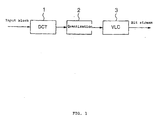
FIG. 1 is a block diagram illustrating a conventional
adaptive DCT coding method.
FIG. 2 is a diagram illustrating the zigzag scanning order.
FIG. 3 is a diagram illustrating the default quantization
matrix.
FIG. 4 is a diagram illustrating the relationship between
the edge direction and the DCT coefficient.
FIG. 5 is a block diagram illustrating the algorithm of this
invention.
FIG. 6 is a block diagram illustrating an application
example of DCT coding in this invention.
FIG. 7 is a diagram illustrating an example of the block
classification.
FIG. 8 is a diagram illustrating the quantization of various
edges in 16 directions.
FIG. 9 is a diagram illustrating the unification of the
nonedge blocks.
FIG. 10 is a diagram illustrating the scanning order S0 used
in the simulation.
FIG. 11 is a diagram illustrating scanning order S4 used in
the simulation.
FIG. 12 is a diagram illustrating an example of the DCT AC
coefficient.
FIG. 13 is a block diagram illustrating an application
example of the edge extraction process in this invention.
FIG. 14 is a diagram illustrating the 8-direction segment
pattern in unit edge detection.
FIG. 15 is a diagram illustrating the macro edge detection.
REFERENCE NUMERALS AS SHOWN IN THE DRAWINGS
10 is an edge extraction step, 11 a block classification
step, 12 an adaptive DCT coding step, 13 a variable block size DCT
step, 14 a quantization step, 15 a scanning order control step,
and 16 a variable-length coding step.
DESCRIPTION OF THE EMBODIMENT
The following is a detailed description of the application
example of this invention including the theoretical discussion.
FIG. 1 is a block diagram illustrating a typical
conventional adaptive DCT coding method.
In the discrete cosine transform (DCT) performed in
block 1,
the block of pixel values is transformed to the matrix of the
horizontal and vertical spatial frequency coefficients. The MXM
2-dimensional DCT is defined as follows.
where, u, v, x, y = 0, 1, 2, ... M-1; x and y represent the sample
region's spatial coordinates; and u and v represent the
coordinates of the transformation region.
The block of pixel values can be reproduced by performing
inverse DCT (IDCT) with respect to the spatial frequency
coefficient.
Usually, most energy is concentrated in the low-frequency
coefficient. The upper-left DCT coefficient in the block is called
DC coefficient. This corresponds to the average pixel value of the
block, and the other terms are called AC coefficients. In this
case, the cases of 16 x 16 and 8 x 8-DCT, which are usually
adopted by the image/video compression algorithm, are considered.
Usually, a natural image can be divided into regions of
different sizes having fine portions of variable parameters and
information. Division of the image to such segments is favorable
for coding with a high efficiency of image data, particularly for
the image compression by means of progressive transmission. Quad
tree (QT) coding is the main scheme representing image
decomposition, that is, multilayer formation. In this case, the
image is divided into 2-dimensional homogeneous square regions,
and a tree is formed by decomposition. Each section of the tree
has four elements, and it is related to the region defined
uniquely for the image. The root is related to the entire image.
Quantization performed in block 2 is performed with the
range of the value represented by a value in the range. The size
of the section of quantization is selected such that as long as
the value of the coefficient is not above a prescribed
quantization level, the human eye will not sense that the
prescribed spatial frequency has been lost. In this way, it is
favorable for generation of the AC coefficient of 0. The
statistical coding of the predicted run of the coefficient with
consecutive 0s of the higher-order coefficient is the reason for
obtaining a reasonable compression gain. In the beginning of the
series, the coefficients that are not 0 are summarized; after the
last nonzero coefficient, the coefficient having as many 0s as
possible is coded. For this purpose, the transformation
coefficient is scanned in the rising order of the spatial
frequency. FIG. 2 shows the so-called zigzag scanning order
prescribed by JPEG and MPEG.
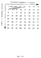
Handling of the DC coefficient is different from that
mentioned previously. That is, eyes are very sensitive to the
large-area brightness error. Consequently, the precision of coding
of the DC value is fixed. FIG. 3 is a diagram illustrating the
default quantization matrix with respect to the interior of the
macro block prescribed in MPEG.
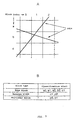
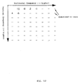
The direction of the edge has a high correlation with the
corresponding DCT coefficient. That is, the DCT coefficient has a
useful property in that it appears in the direction perpendicular
to the direction of the edge. It is well known that when there
exists a block of image having a vertical edge, the corresponding
DCT coefficient having relatively large magnitude appears in the
horizontal direction. This is shown in FIG. 4. Please pay
attention to the fact that the case discussed here corresponds to
type b in this diagram. This correlation property can be used in
the zonal coding. FIG. 4 is a diagram illustrating the
relationship between the edge direction and the DCT coefficient.
In (1), edge types a, b and c correspond to zones A, B and C in
(2), respectively. When the shape of zones A, B and C are defined,
if an appropriate block type can be obtained for each block, it is
possible to reduce the bits for transmission of the coefficient.
This is because, when the area concerned is reduced to the zone,
the entropy pertaining to the position decreases.
The variable-length coding (VLC) performed in
block 3 is a
statistical coding method in which a code word is allotted to the
value to be coded. A shorter code word is allotted to the value
with a higher frequency of generation, while a longer code word is
allotted to the value with a lower frequency of generation. On
average, the frequency is usually dominated by the shorter code
words, and the code string can be shorter than that of the
original data. Consequently, it is possible to shorten the sum of
the code word lengths. As listed in Table I, the VLC data with
respect to DCT coefficient used in MPEG and H. 261 is constructed
by the AC run-level symbol.
FIG. 5 is a diagram illustrating the concept of the
algorithm of this invention. This is characterized by the fact
that it consists of a novel idea that the block classification
process is executed uniquely by using the edge information.
Usually, in the conventional adaptive DCT coding, classification
of blocks is performed in the initial path, and the practical
coding is carried out in the later second path. On the other hand,
in the scheme proposed here, the edges in the overall image are
extracted at first, and the various blocks are then coded.
As mentioned previously, there is a correlation between the
edge direction and the corresponding DCT coefficient distribution.
Consequently, by using this property, it is possible to determine
a group of appropriate scanning order which ensures that the
scanning path up to the last coefficient coded in the block is the
shortest. In other words, the sum run up to the last coefficient
transmitted in the block can be reduced by changing the scanning
order to the adaptive type for each block. Consequently, the
adaptive scanning scheme does not affect the image quality, while
the sum of length of the code words can be reduced with respect to
the transformation coefficient. This is because the coefficient
after the inverse scanning operation in the decoder has to be
totally identical to the nonadaptive-type coding.
In MPEG-2, the other scanning order has been determined,
and, based on its syntax, the scanning order can be switched
between the zigzag scanning order and the other scanning order.
The adaption is performed for each frame. However, in this
application example, it is performed for each block.
The population of the nonedge (free of edge) blocks is in
average in the range of about 20-80%, depending on the contents of
the image. This may not be favorable for the adaptive scanning.
When a coding gain of 10% is obtained for the blocks with edge
(edge blocks), the lowest overall coding gain is 2%. For the
nonedge blocks, the energy compression in the DCT region is larger
than the edge block. Consequently, the nonedge blocks are unified
to the 16 x 16-pixel blocks. Then, the 16 x 16-pixel nonedge
blocks are transformed by the 16 x 16 DCT. Then, the DCT
coefficients are scanned in the zigzag form from the DC
coefficient to the 64th coefficient. In this way, it is possible
to make use of the same VLC table as the 8 x 8 DCT. The
quantization matrix for 16 x 16 block is prepared in the same way
as for 8 x 8 block. In this way, the additional bits for
transmitting the edge blocks can be used. However, there is little
deterioration in the quality carried into the nonedge blocks.
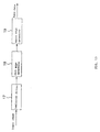
FIG. 6 is a detailed block diagram illustrating an
application example of the adaptive DCT coding (block (12) in FIG.
5) of this invention.
1. Extraction of the edge
The edge on the input image is extracted using the linear
approximate method (block (10) in FIG. 5). This scheme is called
hierarchical edge detection. In order to reduce the overhead,
extraction of the edge for the decimated image is applied. This
has the advantage of reduction of the memory space for block
classification in addition to the complexity of the edge data and
calculation. As a result, the site of the edge has to be
determined precisely so as to ensure that the classification of
the blocks is appropriate for the principal coding process, that
is, the adaptive DCT coding. Consequently, images with 1/4 size
(1/2 in both the horizontal direction and vertical direction) is
used. As a result there is certain change in the classification of
the blocks, there is little deterioration in the overall coding
performance due to the difference. The decimating filter used
relies on selection of the coder. This is because the filter does
not influence the later process much, that is, extraction of the
edge. The edge extraction process will be explained in detail
later.
2. Block classification (block 11 of FIG. 5)
In this stage, the blocks are classified to one of K classes
[Ck, k = 0, ···K-1]. Here, the various classes are related to the
scanning order. The edge data basically comprise coordinates of
the start point, direction, and length. Consequently, the
reproduced edge shows the geometric characteristics of the edge.
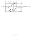
FIG. 7 is a diagram illustrating an example of the block
classification. Classification is made to blocks having two edges
(multiedge blocks) b0, b1; blocks having one edge (edge blocks)
a0, a1, a2, b2, and c0; and blocks free of edge (nonedge blocks)
c1 and c2.
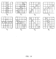
As shown in FIG. 8, the various edges are quantized to 16
directions. Consequently, the various blocks are classified into
as many as 18 classes. That is, with K = 18, it comprises 16 edge
blocks, one multiedge block, and one nonedge block. The multiedge
block refers to a block having two or more edges, and the nonedge
block refers to a block free of any edge. When a 1/4-size image is
used in extraction of edge, 4 x 4 blocks are checked in place of
8 x 8 blocks.
As mentioned previously, the nonedge block is unified to a
16 x 16-pixel block, as shown in FIG. 9. As can be seen from FIG.
9, certain nonedge blocks left as 8 x 8 [blocks] are taken
individually with respect to the 16 x 16 nonedge blocks.
3. Adaptive scanning (block 12 in FIG. 5 and blocks in FIG. 6)
After the block classification is performed, the various
blocks are coded in the scanning order related to the classes
(block 12 in FIG. 5). In detail, first of all, processing of the
variable block size DCT is performed with respect to the input
block (block 13 in FIG. 6). The variable block size DCT can be
realized with the value of M in formula (1) taken as the block
size (for example, M = 16 for the 16 x 16 block DCT). The
classification of the block size is performed based on
presence/absence of the edge. If there exists an edge in the 16 x
16 block, it is divided to four blocks, and is subjected to 8 x 8-block
DCT processing. If there exists no edge, processing is
performed as 16 x 16-block DCT. Then, quantization is carried out
(block 4). As a result this operation is basically identical to
the operation of quantization (block 2) explained in FIG. 1; in
this application example, the quantization matrix shown in FIG. 3
is nevertheless used independent of the class of the block. The
classes in an appropriate number must have a form related to the
distribution of the block DCT coefficients. Consequently, before
coding of the image order, a control mechanism with compatibility
that defines several groups of scanning order is adopted. Then,
for each frame, the optimum scanning order is selected with
respect to the various classes in the frame (block 15 in FIG. 6).
In the simulation, five groups of scanning orders Si, i = 0, 1
···, S-1 (S = 5) are determined. S0 and S4 are as shown in FIGS.
10 and 11. S2 is identical to the zigzag-type scanning as in FIG.
2. S1 is in the middle between S0 and S2. Also, S3 is in the middle
between S4 and S2. Then, the variable-length coding is performed
(block 16). This operation is identical to that of VLC illustrated
by FIG. 1
(block 3).
In the following, how the adaptive scanning method works
will be explained. Suppose there exists a vertical edge in the
block, the DCT AC coefficient corresponding to what should be
transmitted becomes the pattern shown in FIG. 12. It is predicted
that the block is classified as related to S
0, and it is actually
assumed so. In this case, the zigzag scanning order and the code
words corresponding to the DCT coefficients using S
0 are listed in
Table II. In this application example, VLC and quantization
specified by MPEG-1 are used. In this way, it is possible to
reduce 8 bits when the DCT coefficient is coded.
| Zigzag scanning | S0 scanning |
| DCT coefficient | (run, level) | Code length [bit] | DCT coefficient | (run, level) | Code length [bit] |
| 10 | (0, 10) | 13 | 10 | (0, 10) | 13 |
| 4 | (0, 4) | 8 | -6 | (0, -6) | 9 |
| -5 | (1, -5) | 13 | 4 | (0, 4) | 8 |
| -6 | (0, -6) | 9 | 2 | (0, 2) | 5 |
| 2 | (0, 2) | 5 | -5 | (0, -5) | 9 |
| -1 | (7, -1) | 7 | -1 | (0, -1) | 3 |
| Sum bits | 55 | Sum bits | 47 |
In coding of the image sequence, it is necessary to have a
control routine for deriving the optimum scanning for the various
classes. Consequently, the coder has to count generation of the
DCT coefficients sent by the various coordinates to each class.
However, as the zigzag scanning is usually performed, there is no
need to count the coefficients with respect to the 16 x 16 nonedge
block. After processing of the image, s and k are taken as
representing the scanning order and classes, and the judgment
standard δ(s, k) is calculated as follows.
where, s = 0, 1... S-1, and k = 0, 1... K; path [s] [i] [j]
represents the order in (i, j) of scanning s; and cnt [k][i][j]
represents the number of the coefficient in (i, j) of class k.
Then, the aforementioned judgment standard is used to make
the final judgment.
[Formula 4] scan_order[k] = arg_min s δ(s, k)
Consequently, K log2S bits used in displaying which scanning
order is used for the various classes have to be transmitted
before coding of the image. In the simulation, the judgment made
for an image was also used in the next image, and the initial
state of the scanning order is set as follows.
[Formula 5] scan_order[ ] = {0,1,1,2,2,2,3,3,4,3,3,2,2,2,1,1,2,2}
[Extraction of edge]
FIG. 13 can be used to explain in detail the edge extraction
(block 10 in FIG. 5).
FIG. 13 is a block diagram illustrating the edge extraction.
The various portions in this process may be explained as follows.
1. Detection of unit edge (block 18)
In order to find out the site of the edge, first of all, the
well-known Laplace operator is made to adapt to the input image
(block 17). Then, the site with a large variation in the
intensity, that is, the binary image that represents the edge, is
derived by the threshold function using µ + K • σ using the
threshold function. Here, µ, σ, and K represent the average, the
standard deviation in the differential space, and the coefficient,
respectively. FIG. 14 is a diagram illustrating an example of the
segment pattern with small segments in 8 directions. They are
represented as template Tn with n = 0, 1... 7. The inlets at (j,
k) are represented by tn(j, n).
Λ (x, y) is represented by λ (x + j, y + k), with j, k = 0,
1, 2, 3, and 4, and it is the partial region inside the binary
image made of 5 x 5-pixel region. The intercorrelation Rn(x, y)
between template Tn and Λ (x, y) is calculated by the following
formula.
[Formula 6] Rn (x,y) = Σ j Σ k λ(j,k)tn (j - x,k - y)
Then, if there is n for Rn(x, y) to be equal to or larger
than 8, the flag at coordinates (x, y) on the n-bit plane is set
high. Here, n is changed from 0 to 7. This indicates that at
coordinates (x, y), template tn is detected as matching pattern.
This process has to be applied on the entirety of the binary
image. In this way, the unit edge is obtained.
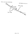
2. Detection of macro edge (block 19)
After the unit edges are extracted, as shown in FIG. 15,
detection of the macro edge is detected. The unit edges are
connected to form a macro edge. This macro edge is determined in
the direction of 16, with a distance of 11.25°. The start point of
detection can be determined as the pixel on which the flag of the
bit plane among eight of them acts. This point is derived by the
raster scanning formula, and it can restrict the searching zone
connected to the lower side of the start point.
Suppose the start point on which the flag in the n-bit plane
acts is determined, direction N of the detection process is
determined by N = 2n, and the searching operation after that is
applied. As there is certain risk in predetermining the direction
of the macro edge before the searching operation, the direction
believed to be the most considered among the three directions
considered, that is, N, N - 1 and N + 1, is selected. In the
various directions under consideration, judgment is made on
whether the macro edge is connected at the various connecting
points for each unit length Lunit along each direction (see FIG.
15). When the flag on the bit plane of n, (N - 1)/2, or (N + 1)/2
is acted by the connecting point or its vicinity, that is, the 8
adjacent pixels, the macro edge is extended to the connecting
point. Among the three candidates of macro edges obtained in this
way, the longest one has the right to become the coded macro edge.
Once the macro edge is detected, in order to avoid extraction of
the same macro edge, it is preferred that a postprocessing be
adopted. The series of pixels corresponding to the macro edge
extracted on certain bit plane of n, (N - 1)/2, or (N + 1)/2 and
the adjacent 8 pixels are taken as neutral. This plays the role of
attenuation of the macro edge, and it helps significantly in
reducing the number of the macro edge extracted in the image.
3. Coding of edge data
Table III lists the message coded for the macro edge. The
message pertaining to the start point can be further compressed by
using appropriate coding scheme.
| Message to be coded | Range | Bit number |
| Start point | Picture size | Log2(horizontal size) + Log2(vertical size) |
| Edge detection | [0, 15] | 4 |
| Edge length | [1, 16] | Variable-length code |
Based on the block classification pertaining to this
invention, preparatory equipment was performed for clarifying the
distribution of the DCT coefficients transmitted for the various
classes.
As the standard model, MPEG-1 I image coding was used. In
order to ensure impartial comparison, the simulation experiment
was performed repeatedly, and the sum number of the bits was
selected as near that of the standard model, that is, MPEG-1, as
possible. Table IV lists the statistical results obtained in the
experiment.
| Name of sequence | Coating algorithm | PSNR [dB] | Average bits/frame (edge data) |
| | | Y | Cb | Cr |
| Susie | MPEG-1 | 31.77 | 42.11 | 41.43 | 25,537 |
| | Proposed | 31.87 | 42.18 | 41.51 | 22,152 (467) |
| Table Tennis | MPEG-1 | 26.05 | 37.63 | 35.53 | 27,125 |
| | Proposed | 26.01 | 37.95 | 36.06 | 24,528 (315) |
| Mother & Daughter | MPEG-1 | 32.87 | 39.31 | 40.64 | 25,059 |
| | Proposed | 32.96 | 39.38 | 40.61 | 23,328 (816) |
| Note | Average bits/frame includes the edge data |
According to this invention, it has been found that the
algorithm can significantly reduce the bits for block
classification. The data speed with respect to the geometric edge
display listed in the table is always 320 x log 2 5. Here, 1,320
corresponds to the number of 8 x 8 blocks inside the image with a
size of 352 x 240, and log2 is needed for indicating the scanning
order among the five candidates with respect to the each block.
This result indicates that this algorithm can reduce the
bits by about 8%, and the performance is generally better than
that of the standard model.
In the above, explanation has been made with respect to the
application example. However, this invention is not limited to
this application example.
For the video signal, high-efficiency good compressed coding
can be realized.