EP0835981A2 - Cutting structure for rotary drill bits - Google Patents
Cutting structure for rotary drill bits Download PDFInfo
- Publication number
- EP0835981A2 EP0835981A2 EP97308020A EP97308020A EP0835981A2 EP 0835981 A2 EP0835981 A2 EP 0835981A2 EP 97308020 A EP97308020 A EP 97308020A EP 97308020 A EP97308020 A EP 97308020A EP 0835981 A2 EP0835981 A2 EP 0835981A2
- Authority
- EP
- European Patent Office
- Prior art keywords
- cutting element
- cutting
- structure according
- carrier
- cutting structure
- Prior art date
- Legal status (The legal status is an assumption and is not a legal conclusion. Google has not performed a legal analysis and makes no representation as to the accuracy of the status listed.)
- Withdrawn
Links
- 238000005520 cutting process Methods 0.000 title claims abstract description 155
- 239000000463 material Substances 0.000 claims abstract description 36
- 230000015572 biosynthetic process Effects 0.000 claims abstract description 30
- 239000000758 substrate Substances 0.000 claims abstract description 21
- 238000005553 drilling Methods 0.000 claims abstract description 15
- 239000012530 fluid Substances 0.000 claims abstract description 11
- 238000005755 formation reaction Methods 0.000 description 24
- UONOETXJSWQNOL-UHFFFAOYSA-N tungsten carbide Chemical compound [W+]#[C-] UONOETXJSWQNOL-UHFFFAOYSA-N 0.000 description 6
- 229910003460 diamond Inorganic materials 0.000 description 4
- 239000010432 diamond Substances 0.000 description 4
- 239000000969 carrier Substances 0.000 description 3
- 230000000694 effects Effects 0.000 description 3
- 230000003628 erosive effect Effects 0.000 description 2
- 238000000034 method Methods 0.000 description 2
- 238000004663 powder metallurgy Methods 0.000 description 2
- 230000008569 process Effects 0.000 description 2
- 238000007493 shaping process Methods 0.000 description 2
- 229910000831 Steel Inorganic materials 0.000 description 1
- 230000004323 axial length Effects 0.000 description 1
- 238000004140 cleaning Methods 0.000 description 1
- 239000011248 coating agent Substances 0.000 description 1
- 238000000576 coating method Methods 0.000 description 1
- 238000001816 cooling Methods 0.000 description 1
- 239000012634 fragment Substances 0.000 description 1
- 238000005552 hardfacing Methods 0.000 description 1
- 230000002452 interceptive effect Effects 0.000 description 1
- 239000011159 matrix material Substances 0.000 description 1
- 229910052751 metal Inorganic materials 0.000 description 1
- 239000002184 metal Substances 0.000 description 1
- 230000004048 modification Effects 0.000 description 1
- 238000012986 modification Methods 0.000 description 1
- 239000002245 particle Substances 0.000 description 1
- 239000010959 steel Substances 0.000 description 1
- 230000007704 transition Effects 0.000 description 1
- XLYOFNOQVPJJNP-UHFFFAOYSA-N water Substances O XLYOFNOQVPJJNP-UHFFFAOYSA-N 0.000 description 1
Images

Classifications
-
- E—FIXED CONSTRUCTIONS
- E21—EARTH DRILLING; MINING
- E21B—EARTH DRILLING, e.g. DEEP DRILLING; OBTAINING OIL, GAS, WATER, SOLUBLE OR MELTABLE MATERIALS OR A SLURRY OF MINERALS FROM WELLS
- E21B10/00—Drill bits
- E21B10/46—Drill bits characterised by wear resisting parts, e.g. diamond inserts
- E21B10/54—Drill bits characterised by wear resisting parts, e.g. diamond inserts the bit being of the rotary drag type, e.g. fork-type bits
- E21B10/55—Drill bits characterised by wear resisting parts, e.g. diamond inserts the bit being of the rotary drag type, e.g. fork-type bits with preformed cutting elements
-
- E—FIXED CONSTRUCTIONS
- E21—EARTH DRILLING; MINING
- E21B—EARTH DRILLING, e.g. DEEP DRILLING; OBTAINING OIL, GAS, WATER, SOLUBLE OR MELTABLE MATERIALS OR A SLURRY OF MINERALS FROM WELLS
- E21B10/00—Drill bits
- E21B10/46—Drill bits characterised by wear resisting parts, e.g. diamond inserts
- E21B10/56—Button-type inserts
- E21B10/567—Button-type inserts with preformed cutting elements mounted on a distinct support, e.g. polycrystalline inserts
- E21B10/5671—Button-type inserts with preformed cutting elements mounted on a distinct support, e.g. polycrystalline inserts with chip breaking arrangements
-
- E—FIXED CONSTRUCTIONS
- E21—EARTH DRILLING; MINING
- E21B—EARTH DRILLING, e.g. DEEP DRILLING; OBTAINING OIL, GAS, WATER, SOLUBLE OR MELTABLE MATERIALS OR A SLURRY OF MINERALS FROM WELLS
- E21B10/00—Drill bits
- E21B10/46—Drill bits characterised by wear resisting parts, e.g. diamond inserts
- E21B10/56—Button-type inserts
- E21B10/567—Button-type inserts with preformed cutting elements mounted on a distinct support, e.g. polycrystalline inserts
- E21B10/5676—Button-type inserts with preformed cutting elements mounted on a distinct support, e.g. polycrystalline inserts having a cutting face with different segments, e.g. mosaic-type inserts
-
- E—FIXED CONSTRUCTIONS
- E21—EARTH DRILLING; MINING
- E21B—EARTH DRILLING, e.g. DEEP DRILLING; OBTAINING OIL, GAS, WATER, SOLUBLE OR MELTABLE MATERIALS OR A SLURRY OF MINERALS FROM WELLS
- E21B10/00—Drill bits
- E21B10/60—Drill bits characterised by conduits or nozzles for drilling fluids
- E21B10/602—Drill bits characterised by conduits or nozzles for drilling fluids the bit being a rotary drag type bit with blades
Definitions
- the invention relates to cutting structures for rotary drag-type drill bits, for use in drilling or coring holes in subsurface formations, and of the kind comprising a bit body having a shank for connection to a drill string, a plurality of cutting structures at the surface of the bit body, and a passage in the bit body for supplying drilling fluid to the surface of the bit body for cooling and/or cleaning the cutters.
- Each cutting structure includes a preform cutting element comprising a front facing table of superhard material bonded to a less hard substrate.
- the cutting element may be mounted on a carrier, also of a material which is less hard than the superhard material, which is mounted on the body of the drill bit, for example, is secured within a socket on the bit body.
- the cutting element may be mounted directly on the bit body, for example the substrate may be of sufficient axial length that it may itself be secured within a socket on the bit body.
- bit body may be machined from metal, usually steel, and sockets to receive the carriers or the cutting elements themselves are machined in the bit body.
- bit body may be moulded from tungsten carbide matrix material using a powder metallurgy process.
- Drag-type drill bits of this kind are particularly suitable for drilling softer formations.
- the shavings or chips of formation gouged from the surface of the borehole not to separate from the surface and to be held down on the surface of the formation by the subsequent passage over the shaving or chip of other cutters and parts of the drill bit.
- bit balling a phenomenon known as "bit balling"
- each design of bit body is only suitable for one arrangement of cutting elements, since the orientation of the cutting elements is determined by the shaped parts of the bit body. It is not possible to employ on the bit body cutting structures in which the cutting elements have orientations (such as back rake, side rake etc.) which differ from those for which the shaped parts of the bit body are suitable.
- each cutting element is mounted on a carrier, so as to form a unitary cutting structure which may be mounted on the bit body as a unit, and it is the carrier, and not the bit body itself, which is shaped to break chips removed from the formation by the cutting element.
- This enables the cutting element and shaped part of the carrier to be accurately matched to one another, in shape, position and orientation, when the cutting structure is manufactured, and this relationship is not affected by the manner in which the cutting structure is subsequently mounted on the bit body, regardless of any tolerances in such fitting.
- bit body merely has to be provided with sockets suitably shaped and located to receive the cutting structures, thus allowing the cutting structures to be mounted in different orientations on different bit bodies of the same design, or allowing different designs of cutting structures to be fitted, all without interfering with the required cooperative relationship between each cutting element and its associated shaped part of the carrier on which it is mounted.
- a cutting structure for a rotary drag-type drill bit including a preform cutting element mounted on a carrier which, in use, is mounted on the drill bit and comprising a front facing table of superhard material bonded to a less hard substrate, wherein a portion of the carrier on which the preform cutting element is mounted is shaped, adjacent the cutting element, for engagement by a chip of formation material being removed by the cutting element from the formation being drilled so as to tend to break the chip away from the surface of the formation.
- the configuration of the cutting structure serves to break the chips away from the surface of the formation, there is less tendency for the chip to be held down on to the surface ofthe borehole or to coagulate on the surface of the bit body to cause bit balling.
- the carrier may be formed of a material which is less hard than the superhard material of the cutting element.
- the carrier may be formed of the same material as the substrate of the preform cutting element.
- the carrier on which the preform cutting element is mounted may be formed with a shaped surface which extends away from the cutting element, on the side thereof remote from its cutting edge, the surface extending from a region which is rearward of the front surface of the facing table, with respect to the normal direction of forward movement of the cutting element in use, to a region which is in front of said front surface.
- Said shaped surface may be smoothly and concavely curved as it extends forwardly away from the cutting element.
- a tangent to the portion of said surface most closely adjacent the cutting element may extend generally parallel to the front surface of the cutting element.
- a tangent to the portion of said surface furthest from the cutting element may extend generally at right angles to the front surface of the cutting element.
- Said shaped surface may comprise two or more substantially planar portions arranged at an angle to one another as they extend away from the cutting element.
- Said shaped surface may comprise a continuation of a surface on said carrier to which the substrate of the cutting element is bonded.
- the shaped surface may include a portion faced with superhard material.
- a further preform compact comprising a front facing table of superhard material bonded to a less hard substrate, may be mounted on said carrier so that the front face ofthe superhard material forms part of said shaped surface on the carrier Preferably the portion of the shaped surface faced with superhard material intersects the plane containing the front surface of the cutting element.
- the present invention also provides arrangements whereby the hydraulic power of the drilling fluid supplied to the surface of the bit body may be employed to assist in the removal of cuttings from the formation or from the cutting elements.
- a cutting structure for a rotary drag-type drill bit including a preform cutting element mounted on a member on the drill bit and comprising a front facing table of superhard material bonded to a less hard substrate, wherein a portion of the member on which the preform cutting element is mounted is shaped, adjacent the cutting element, to direct to a location in front of the cutting element, with respect to the normal direction of forward movement of the cutting element in use, a flow of drilling fluid which impinges on said surface.
- the member on which the preform element is mounted may comprise a carrier which is in turn mounted on the bit body, but in this second aspect of the invention the member may also comprise a part of the bit body itself.
- said shaped surface is formed on a portion of said member which overhangs the front surface of the facing table of the cutting element.
- the surface has an edge adjacent the cutting element, and an imaginary extension of the surface beyond said edge is spaced forwardly of the cutting element.
- the shaped surface is smoothly and concavely curved as it extends towards the cutting element.
- Said shaped surface may be hard faced, for example may have a surface coating of hard facing material applied thereto.
- the shaped surface may include a portion faced with superhard material.
- a further preform compact comprising a front facing table of superhard material bonded to a less hard substrate, may be mounted on the member so that the front face of the superhard material forms part of said shaped surface on the member.
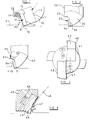
- the body of the drill bit is formed, in well known manner, with a plurality of blades 10 extending generally outwardly away from the central longitudinal axis of rotation of the drill bit. Spaced apart side-by-side along the leading face of each blade is a plurality of cutting structures 11.
- Each cutting structure comprises a cutting element 12 in the form of a circular tablet having a thin front cutting table 13 of polycrystalline diamond or other superhard material bonded in a high pressure, high temperature press to a substrate 14 of less hard material, such as cemented tungsten carbide.
- the cutting element 12 is brazed within a rebate 15 on a generally cylindrical carrier 16 which is also formed from cemented tungsten carbide.
- the cylindrical carrier 16 is received within a correspondingly shaped socket or recess 17 in the blade 10.
- the carrier 16 will usually be brazed or shrink-fitted in the socket.
- the carrier 16 On the side of the cutting element 12 remote from its cutting edge 18, the carrier 16 is formed with a concave surface 19 which extends around a portion of the periphery of the cutting element 12 opposite its cutting edge 18.
- the concave surface 19 may be cylindrical.
- the edge of the curved surface 19 closest to the cutting element 12 meets the cutting element rearwardly of the front face of the facing table 13 and a tangent to the surface at that point is substantially parallel to the front face of the facing table.
- the curved surface 19 then extends to a region forwardly of the facing table 13 to a point where its tangent is substantially at right angles to the front face of the facing table.
- Figure 1 shows the cutting structure in use gouging a shaving or chip 20 from the surface of the formation 21 of the borehole.
- the chip 20 As the chip 20 is lifted from the formation it passes upwardly across the front face of the cutting element 12, and when it engages the curved surface 19, the surface causes it to tend to break into fragments, as indicated diagrammatically 22.
- the chip is thus broken up and the particles can readily be washed away by the drilling fluid that is passing under pressure across the cutting structures, thereby reducing the tendency for cuttings to adhere to the cutting structures or to be held down on the surface of the formation.
- Figure 2 is another arrangement in which the cutting element 29 is mounted on a tungsten carbide carrier 30 which is received in a socket 31 in a blade 32 on the bit body.
- the carrier 30 is generally in the form of part of a sector of a circle and may be generally of the kind described in British Patent Specification No. 2298665.
- the carrier 30 is formed with a shaped concave surface 33 on the side of the cutting element 29 opposite its cutting edge 34.
- the surface 33 forms a continuation of the surface 35 on the carrier 30 to which the cutting element 29 is brazed.
- Figure 3 shows a modification of the arrangement of Figure 2 where the shaped surface comprises two generally planar surfaces 36, 37 arranged at an angle to one another.
- the surface 37 comprises the front surface of the facing table 38 in a preform polycrystalline diamond compact 39 which is brazed into a suitably shaped recess on the carrier 40.
- the compact 39 receives the direct impact of chips being removed from the formation and thus provides the cutting structure with substantial resistance to wear and erosion due to impact by the chips.
- FIG 4 is an end view of a drill bit having a different form of cutting structure according to the invention.
- the bit body 41 is formed with two blades 42 as best seen in Figures 5 and 6, each blade 42 has two circular carriers 43 mounted side-by-side thereon.
- Each carrier 43 is generally circular and is formed on its rear surface with a cylindrical stud portion 44 received in an appropriately shaped socket in the blade 42.
- each carrier 43 has mounted around the lowermost portion of its periphery a number of generally semi-circular preform cutting elements 45.
- Each cutting element 45 comprises a facing table of polycrystalline diamond bonded to a substrate of tungsten carbide and is brazed within a suitably shaped socket 46 in the circular carrier 43.
- the front face of the carrier 43 is formed with a part-spherical concave surface 47 which performs two functions. It acts in similar fashion to the concave surfaces 19, 28, 33 in the arrangements of Figures 1 and 2, but it also directs a jet of drilling fluid 48 from a nozzle 49 associated with the carrier downwardly past the cutting element 45 and on to the formation in front of the cutting element. This also serves to clean the chips of formation from the front of the cutting elements 45 as they are broken up by the curvature 47 in the front face of the carrier.
- the shape of the carriers 43 forms two part-circular groove side-by-side in the formation 50 and the nozzle 49 is so located that the jet 48 of drilling fluid flows around the bottom of the grooves in the formation and sweeps across the cutting elements 45 as indicated by the arrows 51.
- Figure 7 is a diagrammatic section through a cutting structure comprising a polycrystalline diamond preform element 52 mounted on a cemented tungsten carbide carrier 53 which is received in a socket in the bit body (not shown).
- a portion ofthe carrier on the side of the cutting element 52 remote from its cutting edge is formed with a concavely curved surface 55 an imaginary extension of which, as indicated in dotted lines at 56, is spaced forwardly of the cutting element 52.
- a jet 57 of drilling fluid is directed downwardly by the curved surface 55 so as to impinge on chips 58 of formation being raised from the surface of the borehole by the cutting element 52 and breaks the chips away from the cutting element and from the surface of the formation as a result of the hydraulic pressure.
- Figure 8 shows a modified arrangement where the hydraulic effect of Figure 7 is combined with the mechanical effect of Figures 1-3.
- the edge 59 of the concavely curved surface 55 is located forwardly of the front surface of the cutting element 52 so that the chips of formation 58 impinge on the undersurface 60 and are thus mechanically broken up in addition to the breaking up effect of the jet 57 of drilling fluid.
- a PDC element may be set into the surface 55 to resist erosion of the surface by the jet of drilling fluid.
- the interface between the facing table and substrate of the cutting element may be non-planar and configured, instead of being substantially flat, so as to improve the bond between the facing table and substrate and also to provide other advantages, as is well known in the art.
- a transition layer which may, for example, have certain characteristics, such as hardness, which are intermediate the corresponding characteristics of the facing table and substrate.
Abstract
Description
Claims (21)
- A cutting structure for a rotary drag-type drill bit including a preform cutting element mounted on a carrier which, in use, is mounted on the drill bit and comprising a front facing table of superhard material bonded to a less hard substrate, characterised in that a portion of the carrier on which the preform cutting element is mounted is shaped, adjacent the cutting element, for engagement by a chip of formation material being removed by the cutting element from the formation being drilled so as to tend to break the chip away from the surface of the formation.
- A cutting structure according to Claim 1, wherein the carrier is formed of a material which is less hard than the superhard material of the cutting element.
- A cutting structure according to Claim 2, wherein the carrier is formed of the same material as the substrate of the preform cutting element.
- A cutting structure according to any of the preceding claims, wherein the carrier is formed with a shaped surface which extends away from the cutting element, on the side thereof remote from its cutting edge, the surface extending from a region which is rearward of the front surface of the facing table, with respect to the normal direction of forward movement of the cutting element in use, to a region which is in front of said front surface.
- A cutting structure according to Claim 4, wherein said shaped surface is smoothly and concavely curved as it extends forwardly away from the cutting element.
- A cutting structure according to Claim 5, wherein a tangent to the portion of said surface most closely adjacent the cutting element extends generally parallel to the front surface of the cutting element.
- A cutting structure according to Claim 5 or Claim 6, wherein a tangent to the portion of said surface furthest from the cutting element extends generally at right angles to the front surface of the cutting element.
- A cutting structure according to Claim 4, wherein said shaped surface comprises two or more substantially planar portions arranged at an angle to one another as they extend away from the cutting element.
- A cutting structure according to any of Claims 4 to 8, wherein said shaped surface comprises a continuation of a surface on said carrier to which the substrate of the cutting element is bonded.
- A cutting structure according to any of Claims 4 to 9, wherein the shaped surface includes a portion faced with superhard material.
- A cutting structure according to Claim 10, wherein a further preform compact, comprising a front facing table of superhard material bonded to a less hard substrate, is mounted on said carrier so that the front face of the superhard material forms part of said shaped surface on the carrier.
- A cutting structure according to Claim 10 or Claim 11, wherein the portion of the shaped surface faced with superhard material intersects the plane containing the front surface of the cutting element.
- A cutting structure for a rotary drag-type drill bit including a preform cutting element mounted on a member on the drill bit and comprising a front facing table of superhard material bonded to a less hard substrate, characterised in that a portion of the member on *which the preform cutting element is mounted is shaped, adjacent the cutting element, to direct to a location in front of the cutting element, with respect to the normal direction of forward movement of the cutting element in use, a flow of drilling fluid which impinges on said surface.
- A cutting structure according to Claim 13, wherein the shaped member on which the preform element is mounted comprises a carrier which is, in use, mounted on the bit body.
- A cutting structure according to Claim 13, wherein the shaped member on which the preform element is mounted comprises a part of the bit body itself.
- A cutting structure according to any of Claims 13 to 15, wherein said shaped surface is formed on a portion of said member which overhangs the front surface of the facing table of the cutting element.
- A cutting structure according to Claim 16, wherein said shaped surface has an edge adjacent the cutting element, and an imaginary extension of the surface beyond said edge is spaced forwardly of the cutting element.
- A cutting structure according to any of Claims 13 to 17, wherein the shaped surface is smoothly and concavely curved as it extends towards the cutting element.
- A cutting structure according to any of Claims 13 to 18, wherein the shaped surface is hard faced.
- A cutting structure according to any of Claims 13 to 18, wherein the shaped surface includes a portion faced with superhard material.
- A cutting structure according to Claim 20, wherein a further preform compact, comprising a front facing table of superhard material bonded to a less hard substrate, is mounted on the member so that the front face of the superhard material forms part of said shaped surface on the member.
Applications Claiming Priority (2)
| Application Number | Priority Date | Filing Date | Title |
|---|---|---|---|
| GB9621216 | 1996-10-11 | ||
| GBGB9621216.2A GB9621216D0 (en) | 1996-10-11 | 1996-10-11 | Improvements in or relating to cutting structures for rotary drill bits |
Publications (2)
| Publication Number | Publication Date |
|---|---|
| EP0835981A2 true EP0835981A2 (en) | 1998-04-15 |
| EP0835981A3 EP0835981A3 (en) | 1999-03-17 |
Family
ID=10801261
Family Applications (1)
| Application Number | Title | Priority Date | Filing Date |
|---|---|---|---|
| EP97308020A Withdrawn EP0835981A3 (en) | 1996-10-11 | 1997-10-10 | Cutting structure for rotary drill bits |
Country Status (3)
| Country | Link |
|---|---|
| US (1) | US5992549A (en) |
| EP (1) | EP0835981A3 (en) |
| GB (2) | GB9621216D0 (en) |
Cited By (9)
| Publication number | Priority date | Publication date | Assignee | Title |
|---|---|---|---|---|
| US8684112B2 (en) | 2010-04-23 | 2014-04-01 | Baker Hughes Incorporated | Cutting elements for earth-boring tools, earth-boring tools including such cutting elements and related methods |
| US8936659B2 (en) | 2010-04-14 | 2015-01-20 | Baker Hughes Incorporated | Methods of forming diamond particles having organic compounds attached thereto and compositions thereof |
| US9103174B2 (en) | 2011-04-22 | 2015-08-11 | Baker Hughes Incorporated | Cutting elements for earth-boring tools, earth-boring tools including such cutting elements and related methods |
| US9140072B2 (en) | 2013-02-28 | 2015-09-22 | Baker Hughes Incorporated | Cutting elements including non-planar interfaces, earth-boring tools including such cutting elements, and methods of forming cutting elements |
| US9243452B2 (en) | 2011-04-22 | 2016-01-26 | Baker Hughes Incorporated | Cutting elements for earth-boring tools, earth-boring tools including such cutting elements, and related methods |
| US9376867B2 (en) | 2011-09-16 | 2016-06-28 | Baker Hughes Incorporated | Methods of drilling a subterranean bore hole |
| US9428966B2 (en) | 2012-05-01 | 2016-08-30 | Baker Hughes Incorporated | Cutting elements for earth-boring tools, earth-boring tools including such cutting elements, and related methods |
| US9650837B2 (en) | 2011-04-22 | 2017-05-16 | Baker Hughes Incorporated | Multi-chamfer cutting elements having a shaped cutting face and earth-boring tools including such cutting elements |
| US9821437B2 (en) | 2012-05-01 | 2017-11-21 | Baker Hughes Incorporated | Earth-boring tools having cutting elements with cutting faces exhibiting multiple coefficients of friction, and related methods |
Families Citing this family (23)
| Publication number | Priority date | Publication date | Assignee | Title |
|---|---|---|---|---|
| US5447208A (en) * | 1993-11-22 | 1995-09-05 | Baker Hughes Incorporated | Superhard cutting element having reduced surface roughness and method of modifying |
| GB9717505D0 (en) | 1997-08-20 | 1997-10-22 | Camco Int Uk Ltd | Improvements in or relating to cutting structures for rotary drill bits |
| US6328117B1 (en) | 2000-04-06 | 2001-12-11 | Baker Hughes Incorporated | Drill bit having a fluid course with chip breaker |
| US20050247486A1 (en) * | 2004-04-30 | 2005-11-10 | Smith International, Inc. | Modified cutters |
| US7237628B2 (en) * | 2005-10-21 | 2007-07-03 | Reedhycalog, L.P. | Fixed cutter drill bit with non-cutting erosion resistant inserts |
| US8657039B2 (en) | 2006-12-04 | 2014-02-25 | Baker Hughes Incorporated | Restriction element trap for use with an actuation element of a downhole apparatus and method of use |
| US8833492B2 (en) * | 2008-10-08 | 2014-09-16 | Smith International, Inc. | Cutters for fixed cutter bits |
| US20100089661A1 (en) * | 2008-10-13 | 2010-04-15 | Baker Hughes Incorporated | Drill bit with continuously sharp edge cutting elements |
| US8720609B2 (en) * | 2008-10-13 | 2014-05-13 | Baker Hughes Incorporated | Drill bit with continuously sharp edge cutting elements |
| US20100089658A1 (en) * | 2008-10-13 | 2010-04-15 | Baker Hughes Incorporated | Drill bit with continuously sharp edge cutting elements |
| US8020641B2 (en) * | 2008-10-13 | 2011-09-20 | Baker Hughes Incorporated | Drill bit with continuously sharp edge cutting elements |
| US20100224414A1 (en) * | 2009-03-03 | 2010-09-09 | Baker Hughes Incorporated | Chip deflector on a blade of a downhole reamer and methods therefore |
| US20100224419A1 (en) * | 2009-03-03 | 2010-09-09 | Baker Hughes Incorporated | Drill bit with integral cuttings splitter and method of making |
| US8146688B2 (en) * | 2009-04-22 | 2012-04-03 | Baker Hughes Incorporated | Drill bit with prefabricated cuttings splitter and method of making |
| US20100270078A1 (en) * | 2009-04-28 | 2010-10-28 | Baker Hughes Incorporated | Method and apparatus to thwart bit balling of drill bits |
| US8297381B2 (en) | 2009-07-13 | 2012-10-30 | Baker Hughes Incorporated | Stabilizer subs for use with expandable reamer apparatus, expandable reamer apparatus including stabilizer subs and related methods |
| US9441422B2 (en) | 2012-08-29 | 2016-09-13 | National Oilwell DHT, L.P. | Cutting insert for a rock drill bit |
| DK3129577T3 (en) | 2014-04-10 | 2019-08-05 | Varel Int Ind Lp | Ultra-high rope blade reinforcement |
| EP3546692B1 (en) | 2014-04-16 | 2021-03-17 | National Oilwell DHT, L.P. | Downhole drill bit cutting element with chamfered ridge |
| US10307891B2 (en) | 2015-08-12 | 2019-06-04 | Us Synthetic Corporation | Attack inserts with differing surface finishes, assemblies, systems including same, and related methods |
| US10392868B2 (en) * | 2015-09-30 | 2019-08-27 | Schlumberger Technology Corporation | Milling wellbore casing |
| US10900291B2 (en) | 2017-09-18 | 2021-01-26 | Us Synthetic Corporation | Polycrystalline diamond elements and systems and methods for fabricating the same |
| US11585157B2 (en) * | 2020-03-18 | 2023-02-21 | Baker Hughes Oilfield Operations Llc | Earth boring tools with enhanced hydraulics adjacent cutting elements and methods of forming |
Citations (1)
| Publication number | Priority date | Publication date | Assignee | Title |
|---|---|---|---|---|
| US5582258A (en) | 1995-02-28 | 1996-12-10 | Baker Hughes Inc. | Earth boring drill bit with chip breaker |
Family Cites Families (13)
| Publication number | Priority date | Publication date | Assignee | Title |
|---|---|---|---|---|
| US4303136A (en) * | 1979-05-04 | 1981-12-01 | Smith International, Inc. | Fluid passage formed by diamond insert studs for drag bits |
| US4538690A (en) * | 1983-02-22 | 1985-09-03 | Nl Industries, Inc. | PDC cutter and bit |
| US4558753A (en) * | 1983-02-22 | 1985-12-17 | Nl Industries, Inc. | Drag bit and cutters |
| US4907662A (en) * | 1986-02-18 | 1990-03-13 | Reed Tool Company | Rotary drill bit having improved mounting means for multiple cutting elements |
| US4723612A (en) * | 1986-10-31 | 1988-02-09 | Hicks Dusty F | Bit, nozzle, cutter combination |
| CA1302393C (en) * | 1987-10-13 | 1992-06-02 | Gordon A. Tibbitts | Drag bit for drilling in plastic formations with maximum chip clearance and hydraulics for direct chip impingement |
| US4869330A (en) * | 1988-01-20 | 1989-09-26 | Eastman Christensen Company | Apparatus for establishing hydraulic flow regime in drill bits |
| GB2218131B (en) * | 1988-05-06 | 1992-03-25 | Reed Tool Co | Improvements in or relating to rotary drill bits |
| US5115873A (en) * | 1991-01-24 | 1992-05-26 | Baker Hughes Incorporated | Method and appartus for directing drilling fluid to the cutting edge of a cutter |
| US5199511A (en) * | 1991-09-16 | 1993-04-06 | Baker-Hughes, Incorporated | Drill bit and method for reducing formation fluid invasion and for improved drilling in plastic formations |
| US5172778A (en) * | 1991-11-14 | 1992-12-22 | Baker-Hughes, Inc. | Drill bit cutter and method for reducing pressure loading of cutters |
| US5447208A (en) * | 1993-11-22 | 1995-09-05 | Baker Hughes Incorporated | Superhard cutting element having reduced surface roughness and method of modifying |
| GB2298665B (en) * | 1995-03-08 | 1998-11-04 | Camco Drilling Group Ltd | Improvements in or relating to cutter assemblies for rotary drill bits |
-
1996
- 1996-10-11 GB GBGB9621216.2A patent/GB9621216D0/en active Pending
-
1997
- 1997-10-10 GB GB9721408A patent/GB2318371B/en not_active Expired - Lifetime
- 1997-10-10 US US08/949,178 patent/US5992549A/en not_active Expired - Lifetime
- 1997-10-10 EP EP97308020A patent/EP0835981A3/en not_active Withdrawn
Patent Citations (1)
| Publication number | Priority date | Publication date | Assignee | Title |
|---|---|---|---|---|
| US5582258A (en) | 1995-02-28 | 1996-12-10 | Baker Hughes Inc. | Earth boring drill bit with chip breaker |
Cited By (19)
| Publication number | Priority date | Publication date | Assignee | Title |
|---|---|---|---|---|
| US8936659B2 (en) | 2010-04-14 | 2015-01-20 | Baker Hughes Incorporated | Methods of forming diamond particles having organic compounds attached thereto and compositions thereof |
| US8919462B2 (en) | 2010-04-23 | 2014-12-30 | Baker Hughes Incorporated | Cutting elements for earth-boring tools, earth-boring tools including such cutting elements and related methods |
| US10006253B2 (en) | 2010-04-23 | 2018-06-26 | Baker Hughes Incorporated | Cutting elements for earth-boring tools and earth-boring tools including such cutting elements |
| US8684112B2 (en) | 2010-04-23 | 2014-04-01 | Baker Hughes Incorporated | Cutting elements for earth-boring tools, earth-boring tools including such cutting elements and related methods |
| US9650837B2 (en) | 2011-04-22 | 2017-05-16 | Baker Hughes Incorporated | Multi-chamfer cutting elements having a shaped cutting face and earth-boring tools including such cutting elements |
| US9103174B2 (en) | 2011-04-22 | 2015-08-11 | Baker Hughes Incorporated | Cutting elements for earth-boring tools, earth-boring tools including such cutting elements and related methods |
| US10428591B2 (en) | 2011-04-22 | 2019-10-01 | Baker Hughes Incorporated | Structures for drilling a subterranean formation |
| US9243452B2 (en) | 2011-04-22 | 2016-01-26 | Baker Hughes Incorporated | Cutting elements for earth-boring tools, earth-boring tools including such cutting elements, and related methods |
| US10337255B2 (en) | 2011-04-22 | 2019-07-02 | Baker Hughes Incorporated | Cutting elements for earth-boring tools, earth-boring tools including such cutting elements, and related methods |
| US9482057B2 (en) | 2011-09-16 | 2016-11-01 | Baker Hughes Incorporated | Cutting elements for earth-boring tools, earth-boring tools including such cutting elements and related methods |
| US9617792B2 (en) | 2011-09-16 | 2017-04-11 | Baker Hughes Incorporated | Cutting elements for earth-boring tools, earth-boring tools including such cutting elements and related methods |
| US9376867B2 (en) | 2011-09-16 | 2016-06-28 | Baker Hughes Incorporated | Methods of drilling a subterranean bore hole |
| US10385623B2 (en) | 2011-09-16 | 2019-08-20 | Baker Hughes, A Ge Company, Llc | Cutting elements for earth-boring tools and earth-boring tools including such cutting elements |
| US10428590B2 (en) | 2011-09-16 | 2019-10-01 | Baker Hughes, A Ge Company, Llc | Cutting elements for earth-boring tools and earth-boring tools including such cutting elements |
| US9821437B2 (en) | 2012-05-01 | 2017-11-21 | Baker Hughes Incorporated | Earth-boring tools having cutting elements with cutting faces exhibiting multiple coefficients of friction, and related methods |
| US9428966B2 (en) | 2012-05-01 | 2016-08-30 | Baker Hughes Incorporated | Cutting elements for earth-boring tools, earth-boring tools including such cutting elements, and related methods |
| US10066442B2 (en) | 2012-05-01 | 2018-09-04 | Baker Hughes Incorporated | Cutting elements for earth-boring tools, earth-boring tools including such cutting elements, and related methods |
| US11229989B2 (en) | 2012-05-01 | 2022-01-25 | Baker Hughes Holdings Llc | Methods of forming cutting elements with cutting faces exhibiting multiple coefficients of friction, and related methods |
| US9140072B2 (en) | 2013-02-28 | 2015-09-22 | Baker Hughes Incorporated | Cutting elements including non-planar interfaces, earth-boring tools including such cutting elements, and methods of forming cutting elements |
Also Published As
| Publication number | Publication date |
|---|---|
| EP0835981A3 (en) | 1999-03-17 |
| GB2318371A (en) | 1998-04-22 |
| GB2318371B (en) | 2000-01-19 |
| GB9721408D0 (en) | 1997-12-10 |
| GB9621216D0 (en) | 1996-11-27 |
| US5992549A (en) | 1999-11-30 |
Similar Documents
| Publication | Publication Date | Title |
|---|---|---|
| US5992549A (en) | Cutting structures for rotary drill bits | |
| EP0841463B1 (en) | Preform cutting element for rotary drill bits | |
| US5617928A (en) | Elements faced with superhard material | |
| US4823892A (en) | Rotary drill bits | |
| US4718505A (en) | Rotary drill bits | |
| EP0710765B1 (en) | Improvements relating to rotary drill bits | |
| USRE45748E1 (en) | Modified cutters and a method of drilling with modified cutters | |
| CA1237121A (en) | Rotary drill bits and cutting elements for such bits | |
| US5111895A (en) | Cutting elements for rotary drill bits | |
| US4607711A (en) | Rotary drill bit with cutting elements having a thin abrasive front layer | |
| EP1201873B1 (en) | PDC bit with stress relief groove | |
| ZA200104439B (en) | Rotatable cutting bit assembly with cutting inserts. | |
| US4705122A (en) | Cutter assemblies for rotary drill bits | |
| EP0742342A2 (en) | Rotary drill bit | |
| US6065553A (en) | Split blade rotary drag type drill bits | |
| GB2332691A (en) | Fluid directing cutting structure for drill bit | |
| US6164395A (en) | Cutting structure for rotary drill bits | |
| EP0733778B1 (en) | Cutting insert for drag drill bit | |
| EP0384623B1 (en) | Improvements in or relating to cutting elements for rotary drill bits | |
| GB2353056A (en) | Preform cutting element having a chip-breaking protrusion |
Legal Events
| Date | Code | Title | Description |
|---|---|---|---|
| PUAI | Public reference made under article 153(3) epc to a published international application that has entered the european phase |
Free format text: ORIGINAL CODE: 0009012 |
|
| AK | Designated contracting states |
Kind code of ref document: A2 Designated state(s): BE DE |
|
| AX | Request for extension of the european patent |
Free format text: AL;LT;LV;RO;SI |
|
| PUAL | Search report despatched |
Free format text: ORIGINAL CODE: 0009013 |
|
| AK | Designated contracting states |
Kind code of ref document: A3 Designated state(s): AT BE CH DE DK ES FI FR GB GR IE IT LI LU MC NL PT SE |
|
| AX | Request for extension of the european patent |
Free format text: AL;LT;LV;RO;SI |
|
| 17P | Request for examination filed |
Effective date: 19990915 |
|
| AKX | Designation fees paid |
Free format text: BE DE |
|
| 17Q | First examination report despatched |
Effective date: 20020906 |
|
| GRAP | Despatch of communication of intention to grant a patent |
Free format text: ORIGINAL CODE: EPIDOSNIGR1 |
|
| GRAC | Information related to communication of intention to grant a patent modified |
Free format text: ORIGINAL CODE: EPIDOSCIGR1 |
|
| STAA | Information on the status of an ep patent application or granted ep patent |
Free format text: STATUS: THE APPLICATION IS DEEMED TO BE WITHDRAWN |
|
| 18D | Application deemed to be withdrawn |
Effective date: 20051123 |