EP0835949B1 - System of surface treated rotary shaft and vane for refrigerant compressor with refrigerant oil, and corresponding refrigerant compressor - Google Patents
System of surface treated rotary shaft and vane for refrigerant compressor with refrigerant oil, and corresponding refrigerant compressor Download PDFInfo
- Publication number
- EP0835949B1 EP0835949B1 EP97117617A EP97117617A EP0835949B1 EP 0835949 B1 EP0835949 B1 EP 0835949B1 EP 97117617 A EP97117617 A EP 97117617A EP 97117617 A EP97117617 A EP 97117617A EP 0835949 B1 EP0835949 B1 EP 0835949B1
- Authority
- EP
- European Patent Office
- Prior art keywords
- vane
- refrigerant
- rotary shaft
- base material
- refrigerant compressor
- Prior art date
- Legal status (The legal status is an assumption and is not a legal conclusion. Google has not performed a legal analysis and makes no representation as to the accuracy of the status listed.)
- Expired - Lifetime
Links
- 239000003507 refrigerant Substances 0.000 title claims description 88
- 239000010726 refrigerant oil Substances 0.000 title 1
- 239000003921 oil Substances 0.000 claims description 57
- RTZKZFJDLAIYFH-UHFFFAOYSA-N Diethyl ether Chemical compound CCOCC RTZKZFJDLAIYFH-UHFFFAOYSA-N 0.000 claims description 36
- 239000000463 material Substances 0.000 claims description 25
- XEEYBQQBJWHFJM-UHFFFAOYSA-N iron Substances [Fe] XEEYBQQBJWHFJM-UHFFFAOYSA-N 0.000 claims description 23
- 229910001315 Tool steel Inorganic materials 0.000 claims description 21
- 150000002148 esters Chemical class 0.000 claims description 18
- 238000007599 discharging Methods 0.000 claims description 17
- 229910052750 molybdenum Inorganic materials 0.000 claims description 16
- 239000010687 lubricating oil Substances 0.000 claims description 15
- 239000000203 mixture Substances 0.000 claims description 15
- 239000010935 stainless steel Substances 0.000 claims description 12
- 229910001220 stainless steel Inorganic materials 0.000 claims description 12
- 229910052804 chromium Inorganic materials 0.000 claims description 10
- 239000010410 layer Substances 0.000 claims description 9
- 238000000465 moulding Methods 0.000 claims description 9
- 229910052742 iron Inorganic materials 0.000 claims description 7
- 229910001141 Ductile iron Inorganic materials 0.000 claims description 6
- 239000002245 particle Substances 0.000 claims description 6
- ATJFFYVFTNAWJD-UHFFFAOYSA-N Tin Chemical compound [Sn] ATJFFYVFTNAWJD-UHFFFAOYSA-N 0.000 claims description 5
- 238000001746 injection moulding Methods 0.000 claims description 5
- 238000000859 sublimation Methods 0.000 claims description 5
- 230000008022 sublimation Effects 0.000 claims description 5
- NINIDFKCEFEMDL-UHFFFAOYSA-N Sulfur Chemical compound [S] NINIDFKCEFEMDL-UHFFFAOYSA-N 0.000 claims description 4
- 229910052759 nickel Inorganic materials 0.000 claims description 4
- 229910052717 sulfur Inorganic materials 0.000 claims description 4
- 239000011593 sulfur Substances 0.000 claims description 4
- 239000002344 surface layer Substances 0.000 claims description 4
- -1 nitrogen-containing compound Chemical class 0.000 claims description 3
- 238000007789 sealing Methods 0.000 claims description 3
- 238000005245 sintering Methods 0.000 claims description 3
- 238000012360 testing method Methods 0.000 description 16
- 229910000831 Steel Inorganic materials 0.000 description 12
- 239000010959 steel Substances 0.000 description 12
- 238000000034 method Methods 0.000 description 11
- 239000007789 gas Substances 0.000 description 7
- 239000011248 coating agent Substances 0.000 description 6
- 238000000576 coating method Methods 0.000 description 6
- 238000005121 nitriding Methods 0.000 description 6
- CBENFWSGALASAD-UHFFFAOYSA-N Ozone Chemical compound [O-][O+]=O CBENFWSGALASAD-UHFFFAOYSA-N 0.000 description 5
- 229910052799 carbon Inorganic materials 0.000 description 5
- 238000001816 cooling Methods 0.000 description 5
- RWRIWBAIICGTTQ-UHFFFAOYSA-N difluoromethane Chemical compound FCF RWRIWBAIICGTTQ-UHFFFAOYSA-N 0.000 description 5
- 150000002500 ions Chemical class 0.000 description 5
- 239000010802 sludge Substances 0.000 description 5
- OKTJSMMVPCPJKN-UHFFFAOYSA-N Carbon Chemical compound [C] OKTJSMMVPCPJKN-UHFFFAOYSA-N 0.000 description 4
- VOPWNXZWBYDODV-UHFFFAOYSA-N Chlorodifluoromethane Chemical compound FC(F)Cl VOPWNXZWBYDODV-UHFFFAOYSA-N 0.000 description 4
- 239000002253 acid Substances 0.000 description 4
- 229910052782 aluminium Inorganic materials 0.000 description 4
- XAGFODPZIPBFFR-UHFFFAOYSA-N aluminium Chemical compound [Al] XAGFODPZIPBFFR-UHFFFAOYSA-N 0.000 description 4
- 238000004519 manufacturing process Methods 0.000 description 4
- LVGUZGTVOIAKKC-UHFFFAOYSA-N 1,1,1,2-tetrafluoroethane Chemical compound FCC(F)(F)F LVGUZGTVOIAKKC-UHFFFAOYSA-N 0.000 description 3
- 229910001018 Cast iron Inorganic materials 0.000 description 3
- 238000005266 casting Methods 0.000 description 3
- 239000000460 chlorine Substances 0.000 description 3
- 230000000052 comparative effect Effects 0.000 description 3
- 150000001875 compounds Chemical class 0.000 description 3
- GTLACDSXYULKMZ-UHFFFAOYSA-N pentafluoroethane Chemical compound FC(F)C(F)(F)F GTLACDSXYULKMZ-UHFFFAOYSA-N 0.000 description 3
- 238000004381 surface treatment Methods 0.000 description 3
- IJGRMHOSHXDMSA-UHFFFAOYSA-N Atomic nitrogen Chemical compound N#N IJGRMHOSHXDMSA-UHFFFAOYSA-N 0.000 description 2
- ZAMOUSCENKQFHK-UHFFFAOYSA-N Chlorine atom Chemical compound [Cl] ZAMOUSCENKQFHK-UHFFFAOYSA-N 0.000 description 2
- YSMRWXYRXBRSND-UHFFFAOYSA-N TOTP Chemical compound CC1=CC=CC=C1OP(=O)(OC=1C(=CC=CC=1)C)OC1=CC=CC=C1C YSMRWXYRXBRSND-UHFFFAOYSA-N 0.000 description 2
- 150000004996 alkyl benzenes Chemical class 0.000 description 2
- 239000002199 base oil Substances 0.000 description 2
- 239000003575 carbonaceous material Substances 0.000 description 2
- 238000006243 chemical reaction Methods 0.000 description 2
- 229910052801 chlorine Inorganic materials 0.000 description 2
- PXBRQCKWGAHEHS-UHFFFAOYSA-N dichlorodifluoromethane Chemical compound FC(F)(Cl)Cl PXBRQCKWGAHEHS-UHFFFAOYSA-N 0.000 description 2
- 235000019404 dichlorodifluoromethane Nutrition 0.000 description 2
- 230000000694 effects Effects 0.000 description 2
- 239000000835 fiber Substances 0.000 description 2
- 238000005470 impregnation Methods 0.000 description 2
- 238000003754 machining Methods 0.000 description 2
- 229910052751 metal Inorganic materials 0.000 description 2
- 239000002184 metal Substances 0.000 description 2
- 239000002480 mineral oil Substances 0.000 description 2
- 235000010446 mineral oil Nutrition 0.000 description 2
- 150000003839 salts Chemical class 0.000 description 2
- 229910052721 tungsten Inorganic materials 0.000 description 2
- 229910052720 vanadium Inorganic materials 0.000 description 2
- RFCAUADVODFSLZ-UHFFFAOYSA-N 1-Chloro-1,1,2,2,2-pentafluoroethane Chemical compound FC(F)(F)C(F)(F)Cl RFCAUADVODFSLZ-UHFFFAOYSA-N 0.000 description 1
- NLZUEZXRPGMBCV-UHFFFAOYSA-N Butylhydroxytoluene Chemical compound CC1=CC(C(C)(C)C)=C(O)C(C(C)(C)C)=C1 NLZUEZXRPGMBCV-UHFFFAOYSA-N 0.000 description 1
- BVKZGUZCCUSVTD-UHFFFAOYSA-L Carbonate Chemical compound [O-]C([O-])=O BVKZGUZCCUSVTD-UHFFFAOYSA-L 0.000 description 1
- 239000004338 Dichlorodifluoromethane Substances 0.000 description 1
- 239000004593 Epoxy Substances 0.000 description 1
- 229910017389 Fe3N Inorganic materials 0.000 description 1
- MBMLMWLHJBBADN-UHFFFAOYSA-N Ferrous sulfide Chemical compound [Fe]=S MBMLMWLHJBBADN-UHFFFAOYSA-N 0.000 description 1
- 229910000997 High-speed steel Inorganic materials 0.000 description 1
- 238000009825 accumulation Methods 0.000 description 1
- 239000000654 additive Substances 0.000 description 1
- 230000000996 additive effect Effects 0.000 description 1
- 230000002411 adverse Effects 0.000 description 1
- 229910045601 alloy Inorganic materials 0.000 description 1
- 239000000956 alloy Substances 0.000 description 1
- 125000001309 chloro group Chemical group Cl* 0.000 description 1
- 235000019406 chloropentafluoroethane Nutrition 0.000 description 1
- 238000005260 corrosion Methods 0.000 description 1
- 230000007797 corrosion Effects 0.000 description 1
- 230000006378 damage Effects 0.000 description 1
- 230000007423 decrease Effects 0.000 description 1
- 230000001419 dependent effect Effects 0.000 description 1
- 230000008021 deposition Effects 0.000 description 1
- 230000001066 destructive effect Effects 0.000 description 1
- 238000010586 diagram Methods 0.000 description 1
- 239000013013 elastic material Substances 0.000 description 1
- 238000001704 evaporation Methods 0.000 description 1
- 239000011888 foil Substances 0.000 description 1
- 238000010438 heat treatment Methods 0.000 description 1
- 238000005461 lubrication Methods 0.000 description 1
- 238000012986 modification Methods 0.000 description 1
- 230000004048 modification Effects 0.000 description 1
- 150000004767 nitrides Chemical class 0.000 description 1
- 229910052757 nitrogen Inorganic materials 0.000 description 1
- 239000011368 organic material Substances 0.000 description 1
- 229920005862 polyol Polymers 0.000 description 1
- 239000000843 powder Substances 0.000 description 1
- 230000003014 reinforcing effect Effects 0.000 description 1
- 239000000344 soap Substances 0.000 description 1
- 239000000126 substance Substances 0.000 description 1
Images


Classifications
-
- F—MECHANICAL ENGINEERING; LIGHTING; HEATING; WEAPONS; BLASTING
- F01—MACHINES OR ENGINES IN GENERAL; ENGINE PLANTS IN GENERAL; STEAM ENGINES
- F01C—ROTARY-PISTON OR OSCILLATING-PISTON MACHINES OR ENGINES
- F01C21/00—Component parts, details or accessories not provided for in groups F01C1/00 - F01C20/00
- F01C21/08—Rotary pistons
- F01C21/0809—Construction of vanes or vane holders
-
- C—CHEMISTRY; METALLURGY
- C23—COATING METALLIC MATERIAL; COATING MATERIAL WITH METALLIC MATERIAL; CHEMICAL SURFACE TREATMENT; DIFFUSION TREATMENT OF METALLIC MATERIAL; COATING BY VACUUM EVAPORATION, BY SPUTTERING, BY ION IMPLANTATION OR BY CHEMICAL VAPOUR DEPOSITION, IN GENERAL; INHIBITING CORROSION OF METALLIC MATERIAL OR INCRUSTATION IN GENERAL
- C23C—COATING METALLIC MATERIAL; COATING MATERIAL WITH METALLIC MATERIAL; SURFACE TREATMENT OF METALLIC MATERIAL BY DIFFUSION INTO THE SURFACE, BY CHEMICAL CONVERSION OR SUBSTITUTION; COATING BY VACUUM EVAPORATION, BY SPUTTERING, BY ION IMPLANTATION OR BY CHEMICAL VAPOUR DEPOSITION, IN GENERAL
- C23C8/00—Solid state diffusion of only non-metal elements into metallic material surfaces; Chemical surface treatment of metallic material by reaction of the surface with a reactive gas, leaving reaction products of surface material in the coating, e.g. conversion coatings, passivation of metals
- C23C8/06—Solid state diffusion of only non-metal elements into metallic material surfaces; Chemical surface treatment of metallic material by reaction of the surface with a reactive gas, leaving reaction products of surface material in the coating, e.g. conversion coatings, passivation of metals using gases
- C23C8/36—Solid state diffusion of only non-metal elements into metallic material surfaces; Chemical surface treatment of metallic material by reaction of the surface with a reactive gas, leaving reaction products of surface material in the coating, e.g. conversion coatings, passivation of metals using gases using ionised gases, e.g. ionitriding
- C23C8/38—Treatment of ferrous surfaces
-
- F—MECHANICAL ENGINEERING; LIGHTING; HEATING; WEAPONS; BLASTING
- F05—INDEXING SCHEMES RELATING TO ENGINES OR PUMPS IN VARIOUS SUBCLASSES OF CLASSES F01-F04
- F05C—INDEXING SCHEME RELATING TO MATERIALS, MATERIAL PROPERTIES OR MATERIAL CHARACTERISTICS FOR MACHINES, ENGINES OR PUMPS OTHER THAN NON-POSITIVE-DISPLACEMENT MACHINES OR ENGINES
- F05C2201/00—Metals
- F05C2201/04—Heavy metals
- F05C2201/0433—Iron group; Ferrous alloys, e.g. steel
- F05C2201/0436—Iron
- F05C2201/0439—Cast iron
- F05C2201/0442—Spheroidal graphite cast iron, e.g. nodular iron, ductile iron
Definitions
- the present invention relates to a method for treating a metal surface and a member treated by the method, and a refrigerant compressor using the member, and more specifically, relates to a refrigerant compressor used in a freezer where an HFC refrigerant, which does not have the risk of destroying the ozone layer, is used with an improved wear resistance of the sliding surface of a rotary shaft or a vane.
- R-502 which is an azeotropic mixed refrigerant including dichlorodifluoromethane (R-12) or R-22, and monochloropentafluoroethane (R-115a) is used, and such a refrigerant is preferable for an ordinary freezer.
- a refrigerating cycle where a refrigerator oil, compatible with such a refrigerant, including a mineral oil or an alkyl benzene type oil attains a high quality in terms of reliability and durability.
- refrigerants containing little amount of chlorine such as chlorodifluoromethane (HCFC-22, R-22), and refrigerants not containing chlorine such as difluoromethane (HFC-32, R-32), pentafluoroethane (HFC-125, R-125) and 1,1,1,2-tetrafluoroethane (HFC-134a, R-134a) are considered as substitute refrigerants (hereinafter referred to as HFC type refrigerant).
- refrigerator oils used for the HFC type refrigerants include those which are incompatible with the HFC type refrigerants such as a mineral oil and an alkyl benzene type oil, those which are compatible with the HFC type refrigerants such as an ester type refrigerator oil and an ether type refrigerator oil, and a mixture oil thereof.
- the surface of a rotary shaft of a compressor such as a rotary type compressor and a reciprocating type compressor has been applied with surface treatment in order to improve the wear resistance of the sliding surface, such as the salt bath soft nitriding treatment, the ion nitriding treatment, the salt bath sulphonitriding treatment, and the electrolytic sulphonitriding treatment.
- the material of the rotary shaft needs to be a highly elastic ductile cast iron (FCD).
- FCD ductile cast iron
- the center hole of the rotary shaft that is, the hole for circulating the refrigerator oil from the oil pool at the lower part of the refrigerant compressor to the upper part of the refrigerant compressor has been formed conventionally by machining, the machine work becomes difficult. Therefore, a refrigerant compressor comprising a highly elastic rotary shaft where the center hole can be formed economically and easily is strongly called for.
- a vane for a rotary type compressor is made from SKH 51 with the surface treatment for improving the wear resistance such as the ion nitriding treatment and the CrN coating treatment, or is made from an aluminum impregnation carbon material or a fiber reinforced aluminum material.
- the ester type refrigerator oil or the ether type refrigerator oil is hydrolyzed by the moisture existing in the refrigerating circuit due to a high temperature caused by the friction so as to generate an acid.
- a sludge such as a metallic soap is formed due to the generated acid, and thus problems occur such as accumulation of the sludge on the sliding portion of the surface of a vane, corrosion and wearing.
- Patent Abstracts of Japan, Vol. 011, No. 272 (M-622), 4 September 1987, discloses a vane material of high speed tool steel, wherein a surface layer is applied by a nitrosulfurizing process which substantially improves scuffing and wearing resistances.
- Patent Abstracts of Japan, Vol. 004, No. 073 (C-012), 28 May 1980 discloses that the wear resistance is increased if carrying out a nitrosulfurizing process in the presence of a glow discharge.
- An object of the present invention is to provide a refrigerant compressor comprising a rotary shaft or a vane having a low friction coefficient of the rotary shaft or a sliding portion on the surface of the vane, and a high wear resistance even if an ester type refrigerator oil or an ether type refrigerator oil is used as the refrigerator oil, and an HFC type refrigerant is used, to provide a refrigerant compressor comprising a highly elastic rotary shaft where the canter hole can be formed economically and easily, and to provide a refrigerant compressor capable of preventing the generation of a sludge on the sliding portion of the surface of a vane and operating stably over a long time.
- the present inventors have studied to find out that the above-mentioned problems can be solved by the use of a vane made from a high speed tool steel or a vane made from a stainless steel applied with the plasma sulphonitriding treatment on the surface to lead to the present invention. Furthermore, they learned that the above-mentioned problems can be solved by applying the plasma sulphonitriding treatment on the surface of the rotary shaft so as to have a low friction coefficient and an improved wear resistance, and by forming a center hole using a sublimation pattern model or a shell core in the casting stage of the rotary shaft to lead to the present invention.
- a refrigerant compressor comprising a rotary shaft or a vane having a low friction coefficient in a sliding portion on the surface of the rotary shaft or the vane and a high wear resistance can be provided even, in the case an ester type refrigerator oil or an ether type refrigerator oil is used as the refrigerator oil and an HFC type refrigerant is used.
- FIG. 1 is a refrigerating circuit diagram of a freezer.
- FIG. 2 is a vertical cross-sectional view of an embodiment of a refrigerant compressor of the present invention.
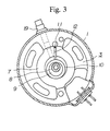
- FIG. 3 is a horizontal cross-sectional view of the refrigerant compressor of FIG. 2.
- FIG. 1 shows a refrigerating cycle of a freezer formed by connecting a refrigerant compressor a of the present invention for compressing and discharging an evaporated gaseous HFC type refrigerant to a condenser, a condenser b for condensing and liquefying the refrigerant, a capillary tube c for reducing the pressure of the refrigerant, and an evaporator d for evaporating the liquefied refrigerant, successively with a tube.
- numeral 1 denotes a hermetically sealed container, having an electric element 2 on the upper side and a rotary compressing element 3 driven by the electric element on the lower side.
- the electric element 2 comprises a stator 5 having a coil 4 insulated with an organic material, and a rotor 6 provided inside the stator 5.
- the rotary compressing element 3 comprises a cylinder 7, a roller 10 rotating along the inner wall of the cylinder 7 in the cylinder driven by an eccentric portion 9 of a rotary shaft 8, a vane 12 pressed by a spring 11 contacting with the circumference of the roller 10 with pressure for separating the inside of the cylinder 7 into a suction side and a discharging side, an upper bearing 13 and a lower bearing 14 for sealing the openings of the cylinder 7 and supporting the rotary shaft 8.
- the upper bearing 13 is provided with a discharging hole 15 communicating with the discharging side of the cylinder 7. Further, a discharging valve 16 for opening/closing the discharging hole 15 and a discharging muffler 17 covering the discharging valve 16 are attached on the upper bearing 13.
- An HFC type refrigerant such as a three component mixture refrigerant including R134a, R32 and R125 (hereinafter referred to as R407C) or a two component mixture refrigerant including R32 and R125 (hereinafter referred to as R410A) is sealed at the bottom of the hermetically sealed container 1.
- the refrigerant flows into the cylinder 7 of the rotary compressing element 3 and is compressed by the cooperation of the roller 10 and the vane 12.
- An ester type refrigerator oil or an ether type refrigerator oil as a refrigerator oil 18 lubricates the sliding surfaces of the roller 10 and the vane 12, which are sliding members of the rotary compressing element 3, or the sliding surface of the rotary shaft 8.
- Numeral 19 denotes a suction tube attached on the hermetically sealed container 1 for guiding the refrigerant to the suction side of the cylinder 7.
- Numeral 20 denotes a discharging tube attached on the upper wall of the hermetically sealed container 1, compressed by the rotary compressing element 3 to discharge the refrigerant outside the hermetically sealed container 1 via the electric element 2.
- the refrigerant flew into the suction side of the cylinder 7 from the suction tube 19 is compressed by the cooperation of the roller 10 and the vane 12 so as to be discharged into the discharging muffler 17 through the discharging hole 15 by opening the discharging valve 16.
- the refrigerant in the discharging muffler 17 is discharged outside the hermetically sealed container 1 from the discharging tube 20 via the electric element 2.
- the oil 18 accommodated at the bottom of the hermetically sealed container 1 is vacuumed through a hollow hole 21 of the rotary shaft 8 by the vacuum phenomenon caused by the swirling generated at the upper open end by the high speed rotation of the rotary shaft 8 so as to be supplied to the sliding surfaces between the sliding members such as the roller 10 and the vane 12 of the rotary compressing element 3, or the sliding surfaces between the rotary shaft 8 and the upper bearing 13 or the lower bearing 14 for lubrication. Further, it prevents leakage of the refrigerant compressed in the cylinder 7 into the lower pressure side.
- the above-mentioned rotary shaft 8 is made from a highly elastic ductile cast iron (FCD), with the surface applied with the plasma sulphonitriding treatment. Therefore, the surface thereof has a low friction coefficient and a high wear resistance. Accordingly, even though a refrigerant is replaced by the HFC type refrigerant and a refrigerator oil is replaced by the ester type refrigerator oil or the ether type refrigerator oil, peel-off of the coating is not generated at the sliding surfaces between the rotary shaft 8 and the upper bearing 13 or the lower bearing 14.
- the vane 12 of the present invention is made from a steel equivalent to a high speed tool steel or a steel equivalent to a stainless steel, with the surface applied with the plasma sulphonitriding treatment.
- the friction coefficient becomes lower owing to a sulfur-containing surface layer portion of iron sulfide generated by the chemical reaction between iron and sulfur on the surface of the rotary shaft 8 or the vane 12 by the plasma sulphonitriding treatment. Further, it is considered that the surface with a high wear resistance can be obtained since the surface is covered with a compound layer generated by the chemical reaction of iron and nitrogen, such as FeN and Fe 3 N 4 . However, the reason is not limited thereto.
- Conditions of the plasma sulphonitriding treatment of the present invention are not particularly limited.
- the internal pressure at the furnace cooling stage is about 3 torr owing to the introduction of a gas.
- the hole 21 is formed in the above-mentioned rotary shaft 8, using the sublimation pattern type or the shell core 21 in the casting stage, it is not necessary to make a hole by machining afterwards.
- the production method of a vane used in the present invention is not particularly limited, but the below-mentioned method of the HIP molding, using a steel equivalent to a high speed tool steel containing the below-mentioned component (which includes a material corresponding to SKH57 and TiN particles (particle size of about 1 to 2 ⁇ m)) is preferable since a vane having an excellent wear resistance can be produced easily in terms of molding.
- the hot isostatic press molding is a method where a powder or a preliminary molding body is sealed and deaerated in metal foil capable of forming a coated body at a high temperature, inserted in a container, heated and sintered while being pressed isotropically through an inert atmosphere medium, which can provide a homogeneous high density sintered body.
- a vane can be molded with the known HIP molding method by adding TiN particles in the material corresponding to SKH57 as mentioned above.
- a hollow vane of a homogeneous high density and a high strength, having a hollow portion, obtained by injection molding and sintering a steel equivalent to a high speed tool steel can be used. It is preferable to use a steel equivalent to a high speed tool steel containing the below-mentioned component for the injection molding. Since the hollow vane is lightweight and significantly strong, a refrigerant compressor with an specification higher than a conventional product by about three times can be achieved by the use of the vane.
- the component and the content are determined so as to allow mass production and to improve the wear resistance particularly of the vane.
- the wear resistance of a vane can be improved by the use of an SUS440 type stainless steel vane having a high Cr content, containing the below-mentioned component as the vane made of the steel equivalent to a stainless steel in the present invention.
- the component and the content are determined so as to allow mass production and to improve the wear resistance particularly of the vane.
- C in the vane Since the content of C in the vane relates to the hardness and the wear resistance after a heat treatment, it needs to be a certain value or within a certain range. In particular, with a value lower than the lower limit, the hardness after hardening and the wear resistance decline. Further, since Cr in the vane is a carbonate deposition element and thus contributes to the wear resistance, an optimum value or an optimum range needs to be selected therefor. W, Mo, V, Co, Si, Mo are also elements to contribute to reinforcing the base, and thus an optimum value or an optimum range needs to be selected therefor since an adverse effect may generate in the wear resistance outside the value or the range.
- the type of a refrigerant compressor of the present invention may be a hermetically sealed type compressor as the above-mentioned or an open type compressor, and thus it is not particularly limited.
- the rotary shaft may be used as the rotary shaft for a rotary type compressor, a reciprocating type compressor, a vibrating type compressor, a multi-vane and rotary type compressor and a scroll type compressor.
- a bench stand test device where a rotary type compressor having the rotary shaft 8 applied with the plasma sulphonitriding treatment, a condenser, an expansion valve, and an evaporator were connected with tubes was used for the endurance test in the below-mentioned testing conditions so as to measure the wearing degree of the sliding portions of the rotary shaft of the rotary type compressor.
- Results of the test showed the wearing degree of the rotary shaft 8 was 1.
- the number shows the five stage rating where 5 denotes bad, 3 tolerable range, and 1 excellent.
- Example 2 In the process the same as Example 1 except that the rotary shaft 8 was applied with the ion nitriding treatment instead of the plasma sulphonitriding treatment, the test was conducted. Results of the test showed that the wearing degree of the rotary shaft 8 was 4.
- a bench stand test device where the rotary type compressor comprising the vane 12 applied with the plasma sulphonitriding treatment, a condenser, an expansion valve, and an evaporator were connected with tubes was used for the endurance test in the below-mentioned testing conditions so as to measure the wearing degree of the sliding portions of the vane 12.
- Results of the test showed the wearing degree of the vane 12 was 1.
- the number shows the five stage rating where 5 denotes bad, 3 tolerable range, and 1 excellent. Even in a long time operation of the rotary type compressor, it was able to operate stably without the rise of the acid value of the oil nor generation of a sludge in the sliding portions of the surface of the vane 12.
- a bench stand test device where the rotary type compressor comprising the vane 12 applied with the plasma sulphonitriding treatment, a condenser, an expansion valve, and an evaporator were connected with tubes was used for the endurance test in the below-mentioned testing conditions so as to measure the wearing degree of the sliding portions of the vane 12.
- Example 2 In the process the same as Example 2 except the vane 12 was treated with the ion nitriding treatment instead of the plasma sulphonitriding treatment, the test was conducted. Results of the test showed that the wearing degree of the vane 12, which partially had peel-off of the coating, was 4.
- a rotary shaft having a low friction coefficient in the surface sliding portions and a high wear resistance can be provided even in the case an ester type refrigerator oil or an ether type refrigerator oil is used as the refrigerator oil and an HFC type refrigerant is used.
- a refrigerant compressor comprising the rotary shaft can operate stably for a long time. Furthermore, the center hole of the rotary shaft can be formed economically and easily.
- a vane having a low friction coefficient in the surface sliding portions and a high wear resistance can be provided even in the case an ester type refrigerator oil or an ether type refrigerator oil is used as the refrigerator oil and an HFC type refrigerant is used.
- a refrigerant compressor comprising the vane can operate stably for a long time.
Landscapes
- Engineering & Computer Science (AREA)
- Chemical & Material Sciences (AREA)
- Mechanical Engineering (AREA)
- General Engineering & Computer Science (AREA)
- Chemical Kinetics & Catalysis (AREA)
- Materials Engineering (AREA)
- Metallurgy (AREA)
- Organic Chemistry (AREA)
- Applications Or Details Of Rotary Compressors (AREA)
- Solid-Phase Diffusion Into Metallic Material Surfaces (AREA)
Description
- The present invention relates to a method for treating a metal surface and a member treated by the method, and a refrigerant compressor using the member, and more specifically, relates to a refrigerant compressor used in a freezer where an HFC refrigerant, which does not have the risk of destroying the ozone layer, is used with an improved wear resistance of the sliding surface of a rotary shaft or a vane.
- As a conventional refrigerant for a freezer, R-502, which is an azeotropic mixed refrigerant including dichlorodifluoromethane (R-12) or R-22, and monochloropentafluoroethane (R-115a) is used, and such a refrigerant is preferable for an ordinary freezer. Further, a refrigerating cycle where a refrigerator oil, compatible with such a refrigerant, including a mineral oil or an alkyl benzene type oil attains a high quality in terms of reliability and durability.
- However, since the above-mentioned refrigerant is highly destructive with respect to the ozone layer and thus it will destroy the ozone layer if it is discharged in the atmosphere and reach the ozone layer in the sky. The destruction of the ozone layer is caused by chlorine atoms (Cl) in a refrigerant.
- Therefore, refrigerants containing little amount of chlorine such as chlorodifluoromethane (HCFC-22, R-22), and refrigerants not containing chlorine such as difluoromethane (HFC-32, R-32), pentafluoroethane (HFC-125, R-125) and 1,1,1,2-tetrafluoroethane (HFC-134a, R-134a) are considered as substitute refrigerants (hereinafter referred to as HFC type refrigerant).
- Examples of refrigerator oils used for the HFC type refrigerants include those which are incompatible with the HFC type refrigerants such as a mineral oil and an alkyl benzene type oil, those which are compatible with the HFC type refrigerants such as an ester type refrigerator oil and an ether type refrigerator oil, and a mixture oil thereof.
- Conventionally, the surface of a rotary shaft of a compressor such as a rotary type compressor and a reciprocating type compressor has been applied with surface treatment in order to improve the wear resistance of the sliding surface, such as the salt bath soft nitriding treatment, the ion nitriding treatment, the salt bath sulphonitriding treatment, and the electrolytic sulphonitriding treatment. However, with the refrigerant replaced by the HFC type refrigerant, and the refrigerator oil replaced by the ester type refrigerator oil or the ether type refrigerator oil, compound layers applied with the conventional treatment (mainly comprising a nitride (ε-Fe3N)) are not sufficient in terms of wear resistance due to a high friction coefficient, and thus it is impossible to operate stably in over a long time. Therefore, an improved treatment method of a rotary shaft, a compressor comprising the treated rotary shaft, such as a rotary type compressor and a reciprocating type compressor are strongly called for.
- Further, with the refrigerant replaced by the HFC type refrigerant and the refrigerator oil replaced by the ester type refrigerator oil or the ether type refrigerator oil, the material of the rotary shaft needs to be a highly elastic ductile cast iron (FCD). However, by the use of a highly elastic material, particularly the FCD, since the center hole of the rotary shaft, that is, the hole for circulating the refrigerator oil from the oil pool at the lower part of the refrigerant compressor to the upper part of the refrigerant compressor has been formed conventionally by machining, the machine work becomes difficult. Therefore, a refrigerant compressor comprising a highly elastic rotary shaft where the center hole can be formed economically and easily is strongly called for.
- On the other hand, a vane for a rotary type compressor is made from SKH 51 with the surface treatment for improving the wear resistance such as the ion nitriding treatment and the CrN coating treatment, or is made from an aluminum impregnation carbon material or a fiber reinforced aluminum material.
- However, with the refrigerant replaced by the HFC type refrigerant and the refrigerator oil replaced by the ester type refrigerator oil or the ether type refrigerator oil, since the friction coefficient is high in the case of the conventional surface treatment such as the ion nitriding treatment, the ester type refrigerator oil or the ether type refrigerator oil is hydrolyzed by the moisture existing in the refrigerating circuit due to a high temperature caused by the friction so as to generate an acid. In this case, a sludge such as a metallic soap is formed due to the generated acid, and thus problems occur such as accumulation of the sludge on the sliding portion of the surface of a vane, corrosion and wearing. Further, in the case of the CrN coating treatment, it involves problems such as peel-off of the coating during the operation and difficulty of production by irregularity of the coated film thickness. In the case of a vane made from an aluminum impregnation carbon material or a fiber reinforced aluminum material, since it is insufficient in terms of the mechanical strength and the wear resistance, and aggressive with respect to the counterpart roller, it is impossible to operate a rotary compressor comprising such a vane stably over a long time.
- Chemical Abstracts, Vol. 101, No. 22, 26 November 1984, Abstract No. 196019, reports iron-sulfonitriding of high speed tool steel.
- Patent Abstracts of Japan, Vol. 011, No. 272 (M-622), 4 September 1987, discloses a vane material of high speed tool steel, wherein a surface layer is applied by a nitrosulfurizing process which substantially improves scuffing and wearing resistances.
- Patent Abstracts of Japan, Vol. 004, No. 073 (C-012), 28 May 1980 discloses that the wear resistance is increased if carrying out a nitrosulfurizing process in the presence of a glow discharge.
- Patent Abstracts of Japan, Vol. 005, No. 160 (C-075), 15 October 1981 and T. Wierzchón: "Erzeugung und Bedeutung der Gasatmosphäre bei der thermochemischen Behandlung im Plasma einer Glimmentladung" HTM, Vol. 36, No. 4, 1981, München, pages 189 - 193, XP002052452 describes sulfonitriding of carbon and alloy steels and glow discharge processes, respectively.
- An object of the present invention is to provide a refrigerant compressor comprising a rotary shaft or a vane having a low friction coefficient of the rotary shaft or a sliding portion on the surface of the vane, and a high wear resistance even if an ester type refrigerator oil or an ether type refrigerator oil is used as the refrigerator oil, and an HFC type refrigerant is used, to provide a refrigerant compressor comprising a highly elastic rotary shaft where the canter hole can be formed economically and easily, and to provide a refrigerant compressor capable of preventing the generation of a sludge on the sliding portion of the surface of a vane and operating stably over a long time.
- This object is achieved by a system as claimed in
claims claim claim 19 and a refrigerant compressor as claimed inclaim 21, respectively; the dependent claims are related to preferred embodiments of the invention. - In order to solve the above-mentioned problems, the present inventors have studied to find out that the above-mentioned problems can be solved by the use of a vane made from a high speed tool steel or a vane made from a stainless steel applied with the plasma sulphonitriding treatment on the surface to lead to the present invention. Furthermore, they learned that the above-mentioned problems can be solved by applying the plasma sulphonitriding treatment on the surface of the rotary shaft so as to have a low friction coefficient and an improved wear resistance, and by forming a center hole using a sublimation pattern model or a shell core in the casting stage of the rotary shaft to lead to the present invention.
- According to the above-mentioned configurations, a refrigerant compressor comprising a rotary shaft or a vane having a low friction coefficient in a sliding portion on the surface of the rotary shaft or the vane and a high wear resistance can be provided even, in the case an ester type refrigerator oil or an ether type refrigerator oil is used as the refrigerator oil and an HFC type refrigerant is used.
- FIG. 1 is a refrigerating circuit diagram of a freezer.
- FIG. 2 is a vertical cross-sectional view of an embodiment of a refrigerant compressor of the present invention.
- FIG. 3 is a horizontal cross-sectional view of the refrigerant compressor of FIG. 2.
- Hereinafter the present invention will be described with reference to FIGs. 1 to 3.
- FIG. 1 shows a refrigerating cycle of a freezer formed by connecting a refrigerant compressor a of the present invention for compressing and discharging an evaporated gaseous HFC type refrigerant to a condenser, a condenser b for condensing and liquefying the refrigerant, a capillary tube c for reducing the pressure of the refrigerant, and an evaporator d for evaporating the liquefied refrigerant, successively with a tube.
- In FIGs. 2 and 3,
numeral 1 denotes a hermetically sealed container, having anelectric element 2 on the upper side and a rotarycompressing element 3 driven by the electric element on the lower side. Theelectric element 2 comprises astator 5 having acoil 4 insulated with an organic material, and arotor 6 provided inside thestator 5. The rotary compressingelement 3 comprises acylinder 7, aroller 10 rotating along the inner wall of thecylinder 7 in the cylinder driven by aneccentric portion 9 of a rotary shaft 8, avane 12 pressed by a spring 11 contacting with the circumference of theroller 10 with pressure for separating the inside of thecylinder 7 into a suction side and a discharging side, anupper bearing 13 and alower bearing 14 for sealing the openings of thecylinder 7 and supporting the rotary shaft 8. - The upper bearing 13 is provided with a
discharging hole 15 communicating with the discharging side of thecylinder 7. Further, a dischargingvalve 16 for opening/closing thedischarging hole 15 and adischarging muffler 17 covering the dischargingvalve 16 are attached on the upper bearing 13. - An HFC type refrigerant, such as a three component mixture refrigerant including R134a, R32 and R125 (hereinafter referred to as R407C) or a two component mixture refrigerant including R32 and R125 (hereinafter referred to as R410A) is sealed at the bottom of the hermetically sealed
container 1. The refrigerant flows into thecylinder 7 of the rotary compressingelement 3 and is compressed by the cooperation of theroller 10 and thevane 12. - An ester type refrigerator oil or an ether type refrigerator oil as a
refrigerator oil 18 lubricates the sliding surfaces of theroller 10 and thevane 12, which are sliding members of the rotary compressingelement 3, or the sliding surface of the rotary shaft 8. - Numeral 19 denotes a suction tube attached on the hermetically sealed
container 1 for guiding the refrigerant to the suction side of thecylinder 7. Numeral 20 denotes a discharging tube attached on the upper wall of the hermetically sealedcontainer 1, compressed by the rotary compressingelement 3 to discharge the refrigerant outside the hermetically sealedcontainer 1 via theelectric element 2. - The refrigerant flew into the suction side of the
cylinder 7 from thesuction tube 19 is compressed by the cooperation of theroller 10 and thevane 12 so as to be discharged into thedischarging muffler 17 through thedischarging hole 15 by opening the dischargingvalve 16. The refrigerant in thedischarging muffler 17 is discharged outside the hermetically sealedcontainer 1 from thedischarging tube 20 via theelectric element 2. - The
oil 18 accommodated at the bottom of the hermetically sealedcontainer 1 is vacuumed through ahollow hole 21 of the rotary shaft 8 by the vacuum phenomenon caused by the swirling generated at the upper open end by the high speed rotation of the rotary shaft 8 so as to be supplied to the sliding surfaces between the sliding members such as theroller 10 and thevane 12 of the rotary compressingelement 3, or the sliding surfaces between the rotary shaft 8 and theupper bearing 13 or thelower bearing 14 for lubrication. Further, it prevents leakage of the refrigerant compressed in thecylinder 7 into the lower pressure side. - The above-mentioned rotary shaft 8 is made from a highly elastic ductile cast iron (FCD), with the surface applied with the plasma sulphonitriding treatment. Therefore, the surface thereof has a low friction coefficient and a high wear resistance. Accordingly, even though a refrigerant is replaced by the HFC type refrigerant and a refrigerator oil is replaced by the ester type refrigerator oil or the ether type refrigerator oil, peel-off of the coating is not generated at the sliding surfaces between the rotary shaft 8 and the
upper bearing 13 or thelower bearing 14. Thevane 12 of the present invention is made from a steel equivalent to a high speed tool steel or a steel equivalent to a stainless steel, with the surface applied with the plasma sulphonitriding treatment. Therefore, the same effect can be achieved as the above-mentioned rotary shaft, and thus peel-off of the coating is not generated at the sliding surfaces between thevane 12 and theroller 10 even though a refrigerant is replaced by the HFC type refrigerant and a refrigerator oil is replaced by the ester type refrigerator oil or the ether type refrigerator oil. - It is considered that the friction coefficient becomes lower owing to a sulfur-containing surface layer portion of iron sulfide generated by the chemical reaction between iron and sulfur on the surface of the rotary shaft 8 or the
vane 12 by the plasma sulphonitriding treatment. Further, it is considered that the surface with a high wear resistance can be obtained since the surface is covered with a compound layer generated by the chemical reaction of iron and nitrogen, such as FeN and Fe3N4. However, the reason is not limited thereto. - Conditions of the plasma sulphonitriding treatment of the present invention are not particularly limited. As a specific example of the treatment conditions, the rotary shaft 8 or the
vane 12 is heated at 540 to 570°C for 1 to 2 hours in a furnace, treated in an atmosphere of N2/H2 = 1:1 for about 2 hours, treated in an N2/H2S mixed gas atmosphere at 540 to 570°C for about 3 hours, and cooled for about 2 hours by furnace cooling. The internal pressure at the furnace cooling stage is about 3 torr owing to the introduction of a gas. - Furthermore, since the
hole 21 is formed in the above-mentioned rotary shaft 8, using the sublimation pattern type or theshell core 21 in the casting stage, it is not necessary to make a hole by machining afterwards. - Since a steel equivalent to a high speed tool steel vane having a content of C, W, and V higher than that of SKH51 of the below-mentioned component is used as the steel equivalent to a high speed tool steel vane of the present invention, the wear resistance of the vane can be further improved.
- Component:
- C : 1.0 to 2.0 wt%, Si : 0.1 to 0.4 wt%,
Mn : 0.2 to 0.5 wt%, Cr : 3.0 to 5.0 wt%,
W : 11.0 to 14.0 wt%, Mo : 0.5 to 2.5 wt%,
V : 3.0 to 5.0 wt%, Fe : remainder. - The production method of a vane used in the present invention is not particularly limited, but the below-mentioned method of the HIP molding, using a steel equivalent to a high speed tool steel containing the below-mentioned component (which includes a material corresponding to SKH57 and TiN particles (particle size of about 1 to 2 µm)) is preferable since a vane having an excellent wear resistance can be produced easily in terms of molding. The hot isostatic press molding (HIP molding) is a method where a powder or a preliminary molding body is sealed and deaerated in metal foil capable of forming a coated body at a high temperature, inserted in a container, heated and sintered while being pressed isotropically through an inert atmosphere medium, which can provide a homogeneous high density sintered body. In the present invention, a vane can be molded with the known HIP molding method by adding TiN particles in the material corresponding to SKH57 as mentioned above.
- Component:
- C : 3.3 to 3.6 wt%, Si : 0.2 to 0.4 wt%,
Mn : 0.2 to 0.4 wt%, Cr : 3.0 to 3.5 wt%
W : 12 to 14 wt%, Mo : 7.0 to 9.0 wt%,
V : 9.0 to 10.5 wt%, Co : 9.0 to 11 wt%,
TiN particles: 13.0 wt% or less, Fe : remainder. - In the present invention, a hollow vane of a homogeneous high density and a high strength, having a hollow portion, obtained by injection molding and sintering a steel equivalent to a high speed tool steel can be used. It is preferable to use a steel equivalent to a high speed tool steel containing the below-mentioned component for the injection molding. Since the hollow vane is lightweight and significantly strong, a refrigerant compressor with an specification higher than a conventional product by about three times can be achieved by the use of the vane.
- Component:
- C : 2.0 to 2.5 wt%, Si : 0.2 to 0.4 wt%,
Mn : 0.2 to 0.4 wt%, Cr : 2 to 6 wt%,
W : 10 to 12 wt%, Mo : 2.0 to 3.0 wt%,
V : 5.0 to 8.0 wt%, Co : 6.0 to 9.0 wt%,
Fe : remainder. - The component and the content are determined so as to allow mass production and to improve the wear resistance particularly of the vane.
- On the other hand, the wear resistance of a vane can be improved by the use of an SUS440 type stainless steel vane having a high Cr content, containing the below-mentioned component as the vane made of the steel equivalent to a stainless steel in the present invention.
- Component:
- C : 0.95 to 1.20 wt%, Si: 1.0 wt% or less,
Mn : 0.6 wt% or less, Ni : 0.6 wt% or less,
Cr : 16 to 18 wt%, Mo : 0.75 wt% or less,
Fe : remainder. - The component and the content are determined so as to allow mass production and to improve the wear resistance particularly of the vane.
- It is preferable to use a vane made of a steel equivalent to a stainless steel obtained by sintering easily in the HIP molding or the injection molding.
- Since the content of C in the vane relates to the hardness and the wear resistance after a heat treatment, it needs to be a certain value or within a certain range. In particular, with a value lower than the lower limit, the hardness after hardening and the wear resistance decline. Further, since Cr in the vane is a carbonate deposition element and thus contributes to the wear resistance, an optimum value or an optimum range needs to be selected therefor. W, Mo, V, Co, Si, Mo are also elements to contribute to reinforcing the base, and thus an optimum value or an optimum range needs to be selected therefor since an adverse effect may generate in the wear resistance outside the value or the range.
- The type of a refrigerant compressor of the present invention may be a hermetically sealed type compressor as the above-mentioned or an open type compressor, and thus it is not particularly limited. The rotary shaft may be used as the rotary shaft for a rotary type compressor, a reciprocating type compressor, a vibrating type compressor, a multi-vane and rotary type compressor and a scroll type compressor.
- Hereinafter the present invention will be explained concretely with reference to Examples and Comparative Examples, but it is not limited to Examples.
- The rotary shaft 8 where the
center hole 21 was formed using a sublimation pattern type or the shell core in the casting stage was placed in a furnace, heated at 570°C for 1 to 2 hours, and treated for 2 hours in an atmosphere where an N2/H2 = 1:1 gas was supplied. Then it was treated for 3 hours in an atmosphere where mixed gases of N2/H2 = 1:1 and N2/H2S = 99:1 were supplied at 570°C. Then it was cooled down for 2 hours by furnace cooling (furnaceinternal pressure 3 torr) and thereby completing the plasma sulphonitriding treatment. - A bench stand test device where a rotary type compressor having the rotary shaft 8 applied with the plasma sulphonitriding treatment, a condenser, an expansion valve, and an evaporator were connected with tubes was used for the endurance test in the below-mentioned testing conditions so as to measure the wearing degree of the sliding portions of the rotary shaft of the rotary type compressor.
- Pressure condition:
- high pressure 27 to 28 kg/cm2·G
low pressure 4.6 kg/cm2·G - Operation frequency:
- 100 Hz
- Operation time:
- 1000 hr,
- Refrigerant:
- R407C produced by Dupont Corp. (a mixed refrigerant of R134a, R32 and R125 with the ratio of 52:23:25)
- Case upper part temperature:
- 95 to 100°C
- Materials of the sliding portions are as mentioned below.
- Vane:
- high speed tool steel (high speed steel)
- Roller:
- cast iron
- Composition (wt%):
- T.C (total carbon): 3.0 to 3.7
Si: 1.5 to 2.5, Mn: 0.5 to 1.0
P : 0.2 to 0.3, S: 0.15 or less
Ni: 0.15 to 0.4, Cr: 0.5 to 1.2
Mo: 0.15 to 0.4, Fe: remainder. - Lubricating oil composition (oil):
- One prepared by adding 0.1 to 2.0% by weight of tricresylphosphate (TCP) and 0.01 to 10% by weight of an additive of an epoxy compound (EP) is added to a base oil, which is a polyol ester type oil (Fureol α68S produced by Japan Energy Corp.). 0.05 to 0.5% by weight of 2,6-di-t-butyl-paracresol is further added to the base oil (hereinafter referred to as OIL-1).
- Results of the test showed the wearing degree of the rotary shaft 8 was 1. The number shows the five stage rating where 5 denotes bad, 3 tolerable range, and 1 excellent.
- In the process the same as Example 1 except that the rotary shaft 8 was applied with the ion nitriding treatment instead of the plasma sulphonitriding treatment, the test was conducted. Results of the test showed that the wearing degree of the rotary shaft 8 was 4.
- The vane made of the steel equivalent to a high speed tool steel containing the below-mentioned component was placed in a furnace, heated at 570°C for 1 to 2 hours, and treated for 2 hours in an atmosphere where an N2/H2 = 1:1 gas was supplied. Then it was treated for 3 hours in an atmosphere where mixed gases of N2/H2 = 1:1 and N2/H2S = 99:1 were supplied at 570°C. Then it was cooled down for 2 hours by furnace cooling (furnace
internal pressure 3 torr) and thereby completing the plasma sulphonitriding treatment. - Component:
- C : 1.0 to 2.0 wt%, Si : 0.1 to 0.4 wt%,
Mn : 0.2 to 0.5 wt%, Cr : 3.0 to 5.0 wt%,
W : 11.0 to 14.0 wt%, Mo : 0.5 to 1.5 wt%,
V : 3.0 to 5.0 wt%, Fe : remainder. - A bench stand test device where the rotary type compressor comprising the
vane 12 applied with the plasma sulphonitriding treatment, a condenser, an expansion valve, and an evaporator were connected with tubes was used for the endurance test in the below-mentioned testing conditions so as to measure the wearing degree of the sliding portions of thevane 12. - Pressure condition:
- high pressure 27 to 28 kg/cm2·G, low pressure 4.6 kg/cm2·G
- Operation frequency:
- 100 Hz
- Operation time:
- 1000 hr,
- Refrigerant:
- R407C produced by Dupont Corp.
- Case upper part temperature:
- 95 to 100°C
- Roller:
- cast iron
- Composition (wt%):
- T.C (total carbon): 3.0 to 3.7
Si: 1.5 to 2.5, Mn: 0.5 to 1.0
P: 0.2 to 0.3, S: 0.15 or less
Ni: 0.15 to 0.4, Cr: 0.5 to 1.2
Mo: 0.15 to 0.4, Fe: remainder. - Lubricating oil composition (oil):
- the above-mentioned OIL-1
- Results of the test showed the wearing degree of the
vane 12 was 1. The number shows the five stage rating where 5 denotes bad, 3 tolerable range, and 1 excellent. Even in a long time operation of the rotary type compressor, it was able to operate stably without the rise of the acid value of the oil nor generation of a sludge in the sliding portions of the surface of thevane 12. - The vane made of a steel equivalent to a stainless steel containing the below-mentioned component was placed in a furnace, heated at 570°C for 1 to 2 hours, and treated for 2 hours in an atmosphere where 1.5 liters/minute of N2 and 1.5 liters/minute of H2 were supplied. Then it was treated for 3 hours in an atmosphere where mixed gases of N2/H2 = 1:1 and N2/H2S = 99:1 were supplied at 570°C. Then it was cooled down for 2 hours by furnace cooling (furnace
internal pressure 3 torr) and thereby completing the plasma sulphonitriding treatment. - Component:
- C : 0.95 to 1.20 wt%, Si : 1.0 wt% or less,
Mn : 0.6 wt% or less, Ni : 0.6 wt% or less,
Cr : 16 to 18 wt%, Mo : 0.75 wt% or less,
Fe : remainder. - A bench stand test device where the rotary type compressor comprising the
vane 12 applied with the plasma sulphonitriding treatment, a condenser, an expansion valve, and an evaporator were connected with tubes was used for the endurance test in the below-mentioned testing conditions so as to measure the wearing degree of the sliding portions of thevane 12. - Pressure condition:
- high pressure 27 to 28 kg/cm2°·G, low pressure 4.6 kg/cm2·G
- Operation frequency:
- 100 Hz
- Operation time:
- 1000 hr,
- Refrigerant:
- R407C produced by Dupont Corp.
- Case upper part temperature:
- 95 to 100°C
- Roller:
- cast iron
- Composition (wt%):
- T.C (total carbon): 3.0 to 3.7
Si: 1.5 to 2.5, Mn: 0.5 to 1.0
P : 0.2 to 0.3, S: 0.15 or less
Ni: 0.15 to 0.4, Cr: 0.5 to 1.2
Mo: 0.15 to 0.4, Fe: remainder. - Lubricating oil composition (oil):
- the above-mentioned OIL-1
- Results of the test showed the wearing degree of the
vane 12 was 1. Even in a long time operation of the rotary type compressor, it was able to operate stably without the rise of the acid value of the oil nor generation of a sludge in the sliding portions of the surface of thevane 12. - In the process the same as Example 2 except the
vane 12 was treated with the ion nitriding treatment instead of the plasma sulphonitriding treatment, the test was conducted. Results of the test showed that the wearing degree of thevane 12, which partially had peel-off of the coating, was 4. - According to the above-mentioned configuration of the present invention, a rotary shaft having a low friction coefficient in the surface sliding portions and a high wear resistance can be provided even in the case an ester type refrigerator oil or an ether type refrigerator oil is used as the refrigerator oil and an HFC type refrigerant is used. A refrigerant compressor comprising the rotary shaft can operate stably for a long time. Furthermore, the center hole of the rotary shaft can be formed economically and easily.
- In addition, according to the above-mentioned configuration of the present invention, a vane having a low friction coefficient in the surface sliding portions and a high wear resistance can be provided even in the case an ester type refrigerator oil or an ether type refrigerator oil is used as the refrigerator oil and an HFC type refrigerant is used. A refrigerant compressor comprising the vane can operate stably for a long time.
- Therefore, a great potential can be provided in terms of industrial applicability by the present invention.
- While the presently preferred embodiments of the present invention have been shown and described, it will be understood that the present invention is not limited thereto, and that various changes and modifications may be made by those skilled in the art without departing from the scope of the invention as set forth in the appended claims.
Claims (22)
- System of a vane in an HFC refrigerant compressor containing a refrigerator oil selected from the group consisting of an ester type lubricating oil, an ether type lubricating oil, and a mixture thereof, and prepared by applying a plasma sulfonitriding treatment on a vane (12) comprising a high speed tool steel as the base material so as to form a nitrogen-containing compound layer and a sulfur-containing surface layer portion on the surface thereof.
- The system according to claim 1, wherein the base material is a high speed tool steel of the below-mentioned components:
- Components:
- C : 1.0 to 2.0 wt%, Si : 0.1 to 0.4 wt%,
Mn: 0.2 to 0.5 wt%, Cr : 3.0 to 5.0 wt%,
W : 11.0 to 14.0 wt%, Mo : 0.5 to 2.5 wt%,
V : 3.0 to 5.0 wt%, Fe : remainder.
- The system according to claim 1, wherein the base material is a high speed tool steel of the below-mentioned components:
- Components:
- C : 2.0 to 2.5 wt%, Si : 0.2 to 0.4 wt%,
Mn: 0.2 to 0.4 wt%, Cr : 2.0 to 6.0 wt%,
W : 10 to 12 wt%, Mo : 2.0 to 3.0 wt%,
V : 5.0 to 8.0 wt%, Co : 6.0 to 9.0 wt%,
Fe : remainder.
- The system according to claim 1, wherein the base material is a high speed tool steel of the below-mentioned components:
- Components:
- C : 3.3 to 3.6 wt%, Si : 0.2 to 0.4 wt%,
Mn: 0.2 to 0.4 wt%, Cr : 3.0 to 3.5 wt%,
W : 12 to 14 wt%, Mo : 7.0 to 9.0 wt%,
V : 9.0 to 10.5 wt%, Co : 9.0 to 11 wt%,
TiN particles: 13.0 wt% or less,
Fe : remainder.
- The system according to claim 4, wherein the base material is molded by the hot isostatic press (HIP) molding.
- The system according to claim 1, comprising a hollow vane obtained by injection-molding of a high speed tool steel.
- A system of a vane in an HFC refrigerant compressor containing a refrigerator oil selected from the group consisting of an ester type lubricating oil, an ether type lubricating oil, and a mixture thereof, and prepared by applying a plasma sulfonitriding treatment on a vane (12) comprising a stainless steel as the base material so as to form a nitrogen-containing compound layer and a sulfur-containing surface layer portion on the surface thereof.
- The system according to claim 7, wherein the base material is a stainless steel of the below-mentioned components:
- Components:
- C : : 0.95 to 1.20 wt%, Si : 1.0 wt% or less,
Mn : 0.6 wt% or less, Ni : 0.6 wt% or less,
Cr : 16 to 18 wt%, Mo : 0.75 wt% or less,
Fe : remainder.
- The system according to claim 7, wherein the stainless steel is sintered.
- A refrigerant compressor comprising an electric element (2) having a rotary shaft (8) and a compressing element (3) driven by the rotary shaft (8) of the electric element, for compressing and discharging a sucked HFC type refrigerant or refrigerant mainly comprising the HFC type refrigerant by the compressing element (3), wherein the compressing element comprises a cylinder (7), a roller (10) rotating in the cylinder driven by an eccentric portion of the rotary shaft (8), a vane (12) for separating the inside of the cylinder (7), and contacting with the roller (10), an upper bearing portion (13) and a lower bearing portion (14) for sealing the openings of the cylinder (7), with the sliding surfaces of the roller and the vane, which are sliding members, are lubricated by a refrigerator oil,
wherein the refrigerator oil is selected from the group consisting of an ester type lubricating oil, an ether type lubricating oil, and a mixture thereof, and the vane (12) is made from a high speed tool steel as a base material applied with the plasma sulfonitriding treatment on the surface of the base material. - The refrigerant compressor according to claim 10, wherein the base material is a high speed tool steel of the below-mentioned components:
- Components:
- C : 1.0 to 2.0 wt%, Si : 0.1 to 0.4 wt%,
Mn: 0.2 to 0.5 wt%, Cr : 3.0 to 5.0 wt%,
W : 11.0 to 14.0 wt%, Mo : 0.5 to 2.5 wt%,
V : 3.0 to 5.0 wt%, Fe : remainder.
- The refrigerant compressor according to claim 10, wherein the base material is a high speed tool steel of the below-mentioned components:
- Components:
- C : 2.0 to 2.5 wt%, Si : 0.2 to 0.4 wt%,
Mn: 0.2 to 0.4 wt%, Cr : 2.0 to 6.0 wt%,
W : 10 to 12 wt%, Mo : 2.0 to 3.0 wt%,
V : 5.0 to 8.0 wt%, Co : 6.0 to 9.0 wt%,
Fe : remainder.
- The refrigerant compressor according to claim 10, wherein the base material is a high speed tool steel of the below-mentioned components:
- Component:
- C : 3.3 to 3.6 wt%, Si : 0.2 to 0.4 wt%,
Mn: 0.2 to 0.4 wt%, Cr : 3.0 to 3.5 wt%,
W : 12 to 14 wt%, Mo : 7.0 to 9.0 wt%,
V : 9.0 to 10.5 wt%, Co : 9.0 to 11 wt%,
TiN particles: 13.0 wt% or less,
Fe : remainder.
- The refrigerant compressor according to claim 13, wherein the base material is molded by the hot isostatic press (HIP) molding.
- The refrigerant compressor according to claim 10, wherein the vane is a hollow vane obtained by injection-molding of a high speed tool steel.
- A refrigerant compressor comprising an electric element (2) having a rotary shaft (8) and a compressing element (3) driven by the rotary shaft (8) of the electric element, for compressing and discharging a sucked HFC type refrigerant or refrigerant mainly comprising the HFC type refrigerant by the compressing element (3), wherein the compressing element comprises a cylinder (7), a roller (10) rotating in the cylinder driven by an eccentric portion of the rotary shaft (8), a vane (12) for separating the inside of the cylinder (7), and contacting with the roller (10), an upper bearing portion (13) and a lower bearing portion (14) for sealing the openings of the cylinder (7), with the sliding surfaces of the roller and the vane, which are sliding members, are lubricated by a refrigerator oil,
wherein the refrigerator oil is selected from the group consisting of an ester type lubricating oil, an ether type lubricating oil, and a mixture thereof, and the vane is made from a stainless steel as a base material applied with a plasma sulfonitriding treatment on the surface of the base material. - The refrigerant compressor according to claim 16, wherein the base material is a stainless steel of the below-mentioned components:
- Components:
- C : 0.95 to 1.20 wt%, Si : 1.0 wt% or less,
Mn : 0.6 wt% or less, Ni : 0.6 wt% or less,
Cr : 16 to 18 wt%, Mo : 0.75 wt% or less,
Fe : remainder.
- The refrigerant compressor according to claim 16, wherein a stainless steel vane obtained by sintering is used.
- A system of a rotary shaft in an HFC refrigerant compressor containing a refrigerator oil selected from the group consisting of an ester type lubricating oil, an ether type lubricating oil, and a mixture thereof, said rotary shaft being made of a ductile cast iron as a base material and on the surface thereof a plasma sulfonitriding treatment is applied.
- The system according to claim 19, comprising a hollow ductile cast iron rotary shaft where a center hole is formed using a sublimation pattern type or a shell core.
- A refrigerant compressor comprising a compressing element and a rotary shaft (8) for driving a compressing element (3), for compressing and discharging a sucked HFC type refrigerant or refrigerant mainly comprising the HFC type refrigerant by the compressing element (3), with the sliding surface of the rotary shaft (8) lubricated by a refrigerator oil, wherein the refrigerator oil is selected from the group consisting of an ester type lubricating oil, an ether type lubricating oil, and a mixture thereof, and a plasma sulfonitriding treatment applied on the surface of a ductile cast iron as the base material of the rotary shaft.
- The refrigerant compressor according to claim 21, wherein the rotary shaft (8) is a hollow ductile cast iron rotary shaft where a center hole is formed using a sublimation pattern type or a shell core.
Applications Claiming Priority (9)
| Application Number | Priority Date | Filing Date | Title |
|---|---|---|---|
| JP27003696 | 1996-10-11 | ||
| JP270036/96 | 1996-10-11 | ||
| JP270032/96 | 1996-10-11 | ||
| JP270035/96 | 1996-10-11 | ||
| JP27003696 | 1996-10-11 | ||
| JP27003596 | 1996-10-11 | ||
| JP27003296 | 1996-10-11 | ||
| JP27003296A JPH10115296A (en) | 1996-10-11 | 1996-10-11 | Refrigerant compressor |
| JP27003596 | 1996-10-11 |
Publications (2)
| Publication Number | Publication Date |
|---|---|
| EP0835949A1 EP0835949A1 (en) | 1998-04-15 |
| EP0835949B1 true EP0835949B1 (en) | 2002-01-16 |
Family
ID=27335766
Family Applications (1)
| Application Number | Title | Priority Date | Filing Date |
|---|---|---|---|
| EP97117617A Expired - Lifetime EP0835949B1 (en) | 1996-10-11 | 1997-10-10 | System of surface treated rotary shaft and vane for refrigerant compressor with refrigerant oil, and corresponding refrigerant compressor |
Country Status (6)
| Country | Link |
|---|---|
| US (1) | US6139296A (en) |
| EP (1) | EP0835949B1 (en) |
| DE (1) | DE69709598T2 (en) |
| ID (1) | ID18849A (en) |
| SG (1) | SG60125A1 (en) |
| TW (1) | TW408212B (en) |
Families Citing this family (13)
| Publication number | Priority date | Publication date | Assignee | Title |
|---|---|---|---|---|
| KR100398563B1 (en) * | 1999-11-15 | 2003-09-19 | 마츠시타 덴끼 산교 가부시키가이샤 | Rotary compressor and method for manufacturing same |
| JP2001263280A (en) * | 2000-03-15 | 2001-09-26 | Sanyo Electric Co Ltd | Rotary compressor |
| JP3723458B2 (en) * | 2001-02-14 | 2005-12-07 | 三洋電機株式会社 | Rotary compressor |
| JP2003184769A (en) * | 2001-12-12 | 2003-07-03 | Hitachi Ltd | Screw compressor and method of manufacturing rotor for screw compressor |
| EP1643128A3 (en) * | 2004-09-30 | 2011-12-14 | Sanyo Electric Co., Ltd. | Compressor |
| US7431576B2 (en) * | 2005-11-30 | 2008-10-07 | Scroll Technologies | Ductile cast iron scroll compressor |
| US8096793B2 (en) * | 2006-03-22 | 2012-01-17 | Scroll Technologies | Ductile cast iron scroll compressor |
| CN101705932A (en) * | 2009-11-04 | 2010-05-12 | 上海齐耀动力技术有限公司 | Piston rod for oil-free lubrication gas compressor |
| JP5679543B2 (en) | 2010-03-29 | 2015-03-04 | Ntn株式会社 | Bearing parts and bearings |
| EP2612035A2 (en) | 2010-08-30 | 2013-07-10 | Oscomp Systems Inc. | Compressor with liquid injection cooling |
| US9267504B2 (en) | 2010-08-30 | 2016-02-23 | Hicor Technologies, Inc. | Compressor with liquid injection cooling |
| JP6028832B2 (en) * | 2014-05-12 | 2016-11-24 | ダイキン工業株式会社 | Compressor manufacturing method |
| AT519398B1 (en) * | 2016-12-06 | 2019-05-15 | Miba Sinter Austria Gmbh | Method for producing a swash plate |
Family Cites Families (12)
| Publication number | Priority date | Publication date | Assignee | Title |
|---|---|---|---|---|
| JPS5538967A (en) * | 1978-09-14 | 1980-03-18 | Hitachi Ltd | Iron base material excellent in wear resistance and manufacture thereof |
| JPS5690972A (en) * | 1979-12-24 | 1981-07-23 | Hitachi Ltd | Production of high strength steel |
| JPS5798668A (en) * | 1980-12-08 | 1982-06-18 | Seiko Epson Corp | Case component for watch |
| JPS5993870A (en) * | 1982-11-17 | 1984-05-30 | Sanyo Electric Co Ltd | Manufacture of vane for rotary compressor |
| JPS6275083A (en) * | 1985-09-27 | 1987-04-06 | Hitachi Ltd | compressor |
| JPH079236B2 (en) * | 1987-01-12 | 1995-02-01 | 株式会社日立製作所 | Rotary compressor |
| JP2818207B2 (en) * | 1989-08-04 | 1998-10-30 | 株式会社日立製作所 | Rotating machine and refrigeration apparatus using the rotating machine |
| US5273410A (en) * | 1989-12-28 | 1993-12-28 | Kabushiki Kaisha Toshiba | Compressor exhibiting an iron sulfide wear surface |
| JPH03281991A (en) * | 1990-03-30 | 1991-12-12 | Toshiba Corp | Coolant compressor |
| JP2607980B2 (en) * | 1990-07-05 | 1997-05-07 | 日立建機株式会社 | Sliding member and gas sulfurizing / nitriding method thereof |
| JPH05340369A (en) * | 1992-06-10 | 1993-12-21 | Hitachi Ltd | Compressor |
| JPH07301188A (en) * | 1994-05-06 | 1995-11-14 | Hitachi Metals Ltd | Compressor |
-
1997
- 1997-10-09 TW TW086114840A patent/TW408212B/en not_active IP Right Cessation
- 1997-10-09 US US08/948,002 patent/US6139296A/en not_active Expired - Lifetime
- 1997-10-10 EP EP97117617A patent/EP0835949B1/en not_active Expired - Lifetime
- 1997-10-10 DE DE69709598T patent/DE69709598T2/en not_active Expired - Lifetime
- 1997-10-10 SG SG1997003719A patent/SG60125A1/en unknown
- 1997-10-13 ID IDP973418A patent/ID18849A/en unknown
Also Published As
| Publication number | Publication date |
|---|---|
| DE69709598D1 (en) | 2002-02-21 |
| SG60125A1 (en) | 1999-02-22 |
| US6139296A (en) | 2000-10-31 |
| TW408212B (en) | 2000-10-11 |
| DE69709598T2 (en) | 2002-09-05 |
| EP0835949A1 (en) | 1998-04-15 |
| ID18849A (en) | 1998-05-14 |
Similar Documents
| Publication | Publication Date | Title |
|---|---|---|
| US6035661A (en) | Refrigerant compressor and cooling apparatus comprising the same | |
| US6139296A (en) | Method for treating metal surface, rotary shaft for refrigerant compressor treated by the method, vane for refrigerant compressor treated by the method, and refrigerant compressor using the same | |
| EP0715079B1 (en) | Refrigerating apparatus and lubricating oil composition | |
| US6948922B2 (en) | Hermetic compressor and open compressor | |
| JP3473776B2 (en) | Hermetic compressor | |
| JPH109170A (en) | Compressor for refrigerator | |
| EP0450847A1 (en) | Refrigerant compressor | |
| CN1239190A (en) | Rotary compressor | |
| KR100508582B1 (en) | Method forr treating metal surface, rotary shaft for refrigerant compressor treated by the method, vane for refrigerant compressor treated by the method, and refrigerant compressor using the same | |
| JPH09189453A (en) | Refrigerating plant | |
| JPH11236890A (en) | Vane and refrigerant compressor using it | |
| JPH10115296A (en) | Refrigerant compressor | |
| JPH10169581A (en) | Vane and coolant compressor using it | |
| JP3708194B2 (en) | Hermetic rotary compressor | |
| JP2001099502A (en) | Refrigeration equipment | |
| JP2001271774A (en) | Rotary compressor | |
| JPH10169582A (en) | Vane and coolant compressor using it | |
| JPH0518357A (en) | Refrigerant compressor | |
| JPH10103276A (en) | Refrigerator | |
| JPH11264393A (en) | Vane and refrigerant compressor using the same | |
| JPH05106581A (en) | Refrigerant compressor | |
| JPH10102079A (en) | Lubricating oil composition | |
| JPH10103271A (en) | Hermetic compressor and refrigerator which uses it | |
| JPH11264392A (en) | Vane and refrigerant compressor using the same | |
| KR0125101Y1 (en) | Hermetic compressor |
Legal Events
| Date | Code | Title | Description |
|---|---|---|---|
| PUAI | Public reference made under article 153(3) epc to a published international application that has entered the european phase |
Free format text: ORIGINAL CODE: 0009012 |
|
| AK | Designated contracting states |
Kind code of ref document: A1 Designated state(s): DE FR GB IT |
|
| 17P | Request for examination filed |
Effective date: 19980602 |
|
| AKX | Designation fees paid |
Free format text: DE FR GB IT |
|
| RBV | Designated contracting states (corrected) |
Designated state(s): DE FR GB IT |
|
| 17Q | First examination report despatched |
Effective date: 19990729 |
|
| GRAG | Despatch of communication of intention to grant |
Free format text: ORIGINAL CODE: EPIDOS AGRA |
|
| RTI1 | Title (correction) |
Free format text: SYSTEM OF SURFACE TREATED ROTARY SHAFT AND VANE FOR REFRIGERANT COMPRESSOR WITH REFRIGERANT OIL, AND CORRESPONDING REFRIGERANT COMPRESSOR |
|
| RTI1 | Title (correction) |
Free format text: SYSTEM OF SURFACE TREATED ROTARY SHAFT AND VANE FOR REFRIGERANT COMPRESSOR WITH REFRIGERANT OIL, AND CORRESPONDING REFRIGERANT COMPRESSOR |
|
| GRAG | Despatch of communication of intention to grant |
Free format text: ORIGINAL CODE: EPIDOS AGRA |
|
| GRAH | Despatch of communication of intention to grant a patent |
Free format text: ORIGINAL CODE: EPIDOS IGRA |
|
| GRAH | Despatch of communication of intention to grant a patent |
Free format text: ORIGINAL CODE: EPIDOS IGRA |
|
| GRAA | (expected) grant |
Free format text: ORIGINAL CODE: 0009210 |
|
| REG | Reference to a national code |
Ref country code: GB Ref legal event code: IF02 |
|
| AK | Designated contracting states |
Kind code of ref document: B1 Designated state(s): DE FR GB IT |
|
| REF | Corresponds to: |
Ref document number: 69709598 Country of ref document: DE Date of ref document: 20020221 |
|
| ET | Fr: translation filed | ||
| PLBE | No opposition filed within time limit |
Free format text: ORIGINAL CODE: 0009261 |
|
| STAA | Information on the status of an ep patent application or granted ep patent |
Free format text: STATUS: NO OPPOSITION FILED WITHIN TIME LIMIT |
|
| 26N | No opposition filed | ||
| PGFP | Annual fee paid to national office [announced via postgrant information from national office to epo] |
Ref country code: FR Payment date: 20141008 Year of fee payment: 18 Ref country code: DE Payment date: 20141007 Year of fee payment: 18 Ref country code: GB Payment date: 20141008 Year of fee payment: 18 |
|
| PGFP | Annual fee paid to national office [announced via postgrant information from national office to epo] |
Ref country code: IT Payment date: 20141015 Year of fee payment: 18 |
|
| REG | Reference to a national code |
Ref country code: DE Ref legal event code: R082 Ref document number: 69709598 Country of ref document: DE |
|
| REG | Reference to a national code |
Ref country code: DE Ref legal event code: R119 Ref document number: 69709598 Country of ref document: DE |
|
| GBPC | Gb: european patent ceased through non-payment of renewal fee |
Effective date: 20151010 |
|
| PG25 | Lapsed in a contracting state [announced via postgrant information from national office to epo] |
Ref country code: DE Free format text: LAPSE BECAUSE OF NON-PAYMENT OF DUE FEES Effective date: 20160503 Ref country code: IT Free format text: LAPSE BECAUSE OF NON-PAYMENT OF DUE FEES Effective date: 20151010 Ref country code: GB Free format text: LAPSE BECAUSE OF NON-PAYMENT OF DUE FEES Effective date: 20151010 |
|
| REG | Reference to a national code |
Ref country code: FR Ref legal event code: ST Effective date: 20160630 |
|
| PG25 | Lapsed in a contracting state [announced via postgrant information from national office to epo] |
Ref country code: FR Free format text: LAPSE BECAUSE OF NON-PAYMENT OF DUE FEES Effective date: 20151102 |