EP0835920A1 - A new photostimulable phosphor - Google Patents
A new photostimulable phosphor Download PDFInfo
- Publication number
- EP0835920A1 EP0835920A1 EP96202816A EP96202816A EP0835920A1 EP 0835920 A1 EP0835920 A1 EP 0835920A1 EP 96202816 A EP96202816 A EP 96202816A EP 96202816 A EP96202816 A EP 96202816A EP 0835920 A1 EP0835920 A1 EP 0835920A1
- Authority
- EP
- European Patent Office
- Prior art keywords
- phosphor
- ray
- light
- phosphors
- photostimulable
- Prior art date
- Legal status (The legal status is an assumption and is not a legal conclusion. Google has not performed a legal analysis and makes no representation as to the accuracy of the status listed.)
- Granted
Links
Images


Classifications
-
- C—CHEMISTRY; METALLURGY
- C09—DYES; PAINTS; POLISHES; NATURAL RESINS; ADHESIVES; COMPOSITIONS NOT OTHERWISE PROVIDED FOR; APPLICATIONS OF MATERIALS NOT OTHERWISE PROVIDED FOR
- C09K—MATERIALS FOR MISCELLANEOUS APPLICATIONS, NOT PROVIDED FOR ELSEWHERE
- C09K11/00—Luminescent materials, e.g. electroluminescent or chemiluminescent
- C09K11/08—Luminescent materials, e.g. electroluminescent or chemiluminescent containing inorganic luminescent materials
- C09K11/77—Luminescent materials, e.g. electroluminescent or chemiluminescent containing inorganic luminescent materials containing rare earth metals
- C09K11/7783—Luminescent materials, e.g. electroluminescent or chemiluminescent containing inorganic luminescent materials containing rare earth metals containing two or more rare earth metals one of which being europium
- C09K11/779—Halogenides
- C09K11/7791—Halogenides with alkali or alkaline earth metals
-
- C—CHEMISTRY; METALLURGY
- C09—DYES; PAINTS; POLISHES; NATURAL RESINS; ADHESIVES; COMPOSITIONS NOT OTHERWISE PROVIDED FOR; APPLICATIONS OF MATERIALS NOT OTHERWISE PROVIDED FOR
- C09K—MATERIALS FOR MISCELLANEOUS APPLICATIONS, NOT PROVIDED FOR ELSEWHERE
- C09K11/00—Luminescent materials, e.g. electroluminescent or chemiluminescent
- C09K11/08—Luminescent materials, e.g. electroluminescent or chemiluminescent containing inorganic luminescent materials
- C09K11/77—Luminescent materials, e.g. electroluminescent or chemiluminescent containing inorganic luminescent materials containing rare earth metals
- C09K11/7728—Luminescent materials, e.g. electroluminescent or chemiluminescent containing inorganic luminescent materials containing rare earth metals containing europium
- C09K11/7732—Halogenides
- C09K11/7733—Halogenides with alkali or alkaline earth metals
-
- G—PHYSICS
- G21—NUCLEAR PHYSICS; NUCLEAR ENGINEERING
- G21K—HANDLING OF PARTICLES OR IONISING RADIATION NOT OTHERWISE PROVIDED FOR; IRRADIATION DEVICES; GAMMA RAY OR X-RAY MICROSCOPES
- G21K4/00—Conversion screens for the conversion of the spatial distribution of X-rays or particle radiation into visible images, e.g. fluoroscopic screens
-
- G—PHYSICS
- G21—NUCLEAR PHYSICS; NUCLEAR ENGINEERING
- G21K—HANDLING OF PARTICLES OR IONISING RADIATION NOT OTHERWISE PROVIDED FOR; IRRADIATION DEVICES; GAMMA RAY OR X-RAY MICROSCOPES
- G21K4/00—Conversion screens for the conversion of the spatial distribution of X-rays or particle radiation into visible images, e.g. fluoroscopic screens
- G21K2004/06—Conversion screens for the conversion of the spatial distribution of X-rays or particle radiation into visible images, e.g. fluoroscopic screens with a phosphor layer
-
- Y—GENERAL TAGGING OF NEW TECHNOLOGICAL DEVELOPMENTS; GENERAL TAGGING OF CROSS-SECTIONAL TECHNOLOGIES SPANNING OVER SEVERAL SECTIONS OF THE IPC; TECHNICAL SUBJECTS COVERED BY FORMER USPC CROSS-REFERENCE ART COLLECTIONS [XRACs] AND DIGESTS
- Y10—TECHNICAL SUBJECTS COVERED BY FORMER USPC
- Y10S—TECHNICAL SUBJECTS COVERED BY FORMER USPC CROSS-REFERENCE ART COLLECTIONS [XRACs] AND DIGESTS
- Y10S430/00—Radiation imagery chemistry: process, composition, or product thereof
- Y10S430/167—X-ray
- Y10S430/168—X-ray exposure process
Definitions
- the present invention relates to a storage phosphor which emits fluorescent light on photostimulation after being exposed to penetrating radiation.
- penetrating radiation which is high energy radiation also known as ionizing radiation belonging to the class of X-rays, gamma-rays and high-energy elementary particle radiation, e.g. beta-rays, electron beam or neutron radiation.
- penetrating radiation For the conversion of penetrating radiation into visible light and/or ultraviolet radiation luminescent substances, called phosphors, are used.
- an X-ray radiograph is obtained by X-rays transmitted imagewise through an object and converted into light of corresponding intensity in a so-called intensifying screen (X-ray conversion screen) wherein phosphor particles absorb the transmitted X-rays and convert them into visible light and/or ultraviolet radiation to which a photographic film is more sensitive than to the direct impact of X-rays.
- intensifying screen X-ray conversion screen
- the light emitted imagewise by said screen irradiates a contacting photographic silver halide emulsion layer film which after exposure is developed to form therein a silver image in conformity with the X-ray image.
- an X-ray recording system wherein photostimulable storage phosphors are used having in addition to their immediate light emission (prompt emission) on X-ray irradiation the property to store temporarily a large part of the X-ray energy. Said energy is set free by photostimulation in the form of fluorescent light different in wavelength from the light used in the photostimulation.
- said X-ray recording system the light emitted on photostimulation is detected photoelectronically and transformed into sequential electrical signals.
- the basic constituents of such X-ray imaging system operating with a photostimulable storage phosphor are an imaging sensor containing said phosphor in particulate form normally in a plate or panel, which temporarily stores the X-ray energy pattern, a scanning laser beam for photostimulation, a photoelectronic light detector providing analogue signals that are converted subsequently into digital time-series signals, normally a digital image processor which manipulates the image digitally, a signal recorder, e.g. magnetic disk or tape, and an image recorder for modulated light exposure of a photographic film or an electronic signal display unit, e.g. cathode-ray tube.
- a survey of lasers useful in the read-out of photostimulable latent fluorescent images is given in the periodical Research Disclosure December 1989, item 308117.
- a method for recording and reproducing a radiation image comprising the steps of (i) causing a visible ray- or infrared ray-stimulable phosphor to absorb a radiation passing through an object, (ii) stimulating said phosphor with stimulation rays selected from visible rays and infrared rays to release the energy of the radiation stored therein as fluorescent light, characterized in that said phosphor is at least one phosphor selected from the group of alkaline earth metal fluorohalide phosphors represented by the formula (Ba 1-x M x II )FX:yA wherein :
- the signal-to-noise ratio of the recorded image should be as high as possible.
- BaFBr:Eu 2+ storage phosphors used in digital radiography, have a relatively high X-ray absorption in the range from 30-120 keV, which is relevant for general medical radiography, the absorption is lower than the X-ray absorption of most prompt-emitting phosphors used in screen/film radiography, like e.g. LaOBr:Tm, Gd 2 O 2 S:Tb and YTaO 4 :Nb. Therefore, LaOBr:Tm, Gd 2 O 2 S:Tb or YTaO 4 :Nb screens will absorb a larger fraction of the irradiated X-ray quanta than BaFBr:Eu screens of equal thickness.
- the signal to noise ratio (SNR) of an X-ray image being proportional to the square-root of the absorbed X-ray dose, the images made with LaOBr:Tm, Gd 2 O 2 S:Tb or YTaO 4 :Nb screens will be less noisy than images made with BaFBr:Eu screens having the same thickness.
- a larger fraction of X-ray quanta will be absorbed when thicker BaFBr:Eu screens are used.
- Use of thicker screens leads to diffusion of light over larger distances in the screen, which causes deterioration of image resolution. For this reason, X-ray images made with digital radiography, using BaFBr screens, as disclosed in US 4,239,968, give a more noisy impression than images made with screen/film radiography.
- BaFX:Eu phosphors containing large amounts of iodine have been described e.g. in EP-A 142 734, the general formula of said phosphor is BaF(Br 1-x I x ):yEu, and 10 -3 ⁇ x ⁇ 1.0.
- Fig. 3 of said patent the relative luminance of BaFX:Eu storage phosphors is shown as a function of the iodine content. It is clear from said Fig.
- the portion of Br that is replaced by I should preferably not be made higher than 50 % since replacement of a larger portion of Br by I, leads to a lower relative luminance, of the light emitted upon stimulation.
- the relative luminance of the storage phosphor should be as high as possible, since the sensitivity of a storage phosphor system is proportional to the storage phosphor luminance and apart from a high X-ray absorption, a high system sensitivity is essential for reducing image noise.
- the gain in image quality, due to the higher absorption of X-rays when more than 50 % of iodine is included in the phosphor is offset by the lowering of the relative luminance.
- EP-A 533 236 a divalent europium activated stimulable phosphor is claimed wherein the stimulated light has a higher intensity when the stimulation proceeds with light of 550 nm, than when the stimulation proceeds with light of 600 nm. It is said that in said phosphor a "minor part" of bromine is replaced by chlorine and/or iodine. By minor part has to be understood less than 50 atom %.
- 0.06 ⁇ x ⁇ 0.20, 0.85 ⁇ a + b ⁇ 0.96, M 1+ is Cs or Rb, M 2+ is Pb, 10 -4 ⁇ y ⁇ 10 -3 , 10 -4 ⁇ p ⁇ 10 -1 and q 0.
- Fig.1 shows the relative X-ray absorption of a bariumfluorohalide phosphor as a function of the iodine content.
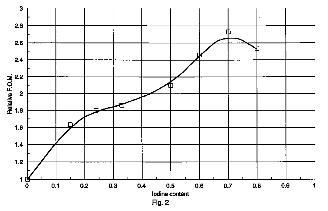
- Fig.2 shows the relative F.O.M. (figure of merit) of bariumfluorohalide phosphors according to this invention as a function of the iodine content.
- the absorption a phosphor with, e.g., 40 % of the bromine replaced by iodine is taken 1
- the absorption a phosphor with, e.g. 80 % of the bromine replaced by iodine is 1.11
- phosphor the luminance of a phosphor, wherein 80 % of the bromine is replaced by iodine is 20 % higher than that of a phosphor wherein 50 % of the bromine has been replaced.
- a stimulable phosphor according to the present invention wherein 80 % of the bromine is replaced by iodine, will show a speed that is about 30 % higher than the speed of a phosphor wherein only 40 % of the bromine is replaced by iodine.
- the speed of a photostimulable panel comprising said phosphor can better be "tailor made", i.e. adjusted and adapted to the signal-to-noise ratio necessary in the different medical applications than with prior art phosphors.
- the present invention encompasses thus photostimulable phosphors according to formula (I) : Ba 1-x-y-p-3q-z Sr x M y 2+ M 2p 1+ M 2q 3+ F 2-a-b Br a I b :zEu wherein :
- Phosphors according to the present invention can be produced according to any way known in the art, starting from phosphor precursors that are to be incorporated in the phosphor. These phosphor precursors are mixed in the appropriate stoechiometric proportions and are then heated for a given time. After cooling, the sintered block of phosphor is milled into fine phosphor particles. The milling operation continues until a phosphor powder with the appropriate average particle size and size distribution is obtained. Optionally the milled phosphor powder can be classified in separate fractions with a specific particle size distribution. During the preparation of the phosphor any known flux materials can be added to the reaction mixture.
- Flux materials useful for use in the preparation of the phosphors according to the invention are, e.g., halides, metasilicates of alkali metals or alkaline earth metals. Most preferred are fluxes comprising halides of the alkali metals or alkaline earth metals that are already present in the raw mix.
- a very useful and preferred method for the preparation of stimulable phosphors according to the present invention can be found in Research Disclosure Volume 358, February 1994 p 93 item 35841, that is incorporated herein by reference.
- any known method for preparing X-ray phosphors comprises the steps of :
- the phosphor particles for use in the method according to the present invention are preferably classified. This classification, ensures that the size distribution of the phosphor particles comprises at most 20 % by weight, preferably at most 10 % by weight, of particles with a diameter lower than 1 ⁇ m. The absence of small phosphor particles (phosphor particles with diameter ⁇ 1 ⁇ m) had a beneficial effect on the image quality.
- the phosphor can present in dispersed form in a binder layer that may be supported or self-supporting and forms a screen or panel.
- the binder layer incorporates said phosphor in dispersed form preferably in (a) film forming organic polymer(s), e.g. a cellulose acetate butyrate, polyalkyl (meth)acrylates, e.g. polymethyl methacrylate, a polyvinyl-n-butyral e.g. as described in the US-P 3,043,710, a copoly(vinyl acetate/vinyl chloride) and a copoly(acrylonitrile/butadiene/styrene) or a copoly(vinyl chloride/vinyl acetate/vinyl alcohol) or mixture thereof.
- organic polymer(s) e.g. a cellulose acetate butyrate
- polyalkyl (meth)acrylates e.g. polymethyl methacrylate
- a polyvinyl-n-butyral e.g. as described in the US-P 3,043,710
- the weight ratio of phosphor to binder preferably from 80:20 to 99:1.
- the ratio by volume of phosphor to binding medium is preferably more than 85/15.
- the binding medium substantially consists of one or more hydrogenated styrene-diene block copolymers, having a saturated rubber block, as rubbery and/or elastomeric polymers as disclosed in WO 94/00531.
- Particularly suitable thermoplastic rubbers, used as block-copolymeric binders in phosphor screens in accordance with this invention are the KRATON-G rubbers, KRATON being a trade mark name from SHELL.
- the coverage of the phosphor is preferably in the range from about 5 and 250 mg/cm 2 , most preferably between 20 and 175 mg/cm 2 .
- the stimulable phosphor used according to the present invention is preferably protected against the influence of moisture by adhering thereto chemically or physically a hydrophobic or hydrophobizing substance. Suitable substances for said purpose are described e.g. in US-P 4,138,361.
- the phosphor layer is used as a supported layer on a support sheet.
- Suitable support materials are made of a film forming organic resin, e.g. polyethylene terephthalate, but paper supports and cardboard supports optionally coated with a resin layer such as an alpha-olefinic resin layer are also particularly useful. Further are mentioned glass supports and metal supports.
- the thickness of the phosphor layer is preferably in the range of 0.05 mm to 0.5 mm.
- the phosphor particles are intimately dispersed in a solution of the binder and then coated on the support and dried.
- the coating of the present phosphor binder layer may proceed according to any usual technique, e.g. by spraying, dip-coating or doctor blade coating. After coating, the solvent(s) of the coating mixture is (are) removed by evaporation, e.g. by drying in a hot (60 °C) air current.
- An ultrasonic treatment can be applied to improve the packing density and to perform the de-aeration of the phosphor-binder combination.
- the phosphor-binder layer may be calendered to improve the packing density (i.e. the number of grams of phosphor per cm 3 of dry coating).
- a light-reflecting layer is provided between the phosphor-containing layer and its support to enhance the output of light emitted by photostimulation.
- a light-reflecting layer may contain white pigment particles dispersed in a binder, e.g. titanium dioxide particles, or it may be made of a vapour-deposited metal layer, e.g. an aluminium layer, or it may be a coloured pigment layer absorbing stimulating radiation but reflecting the emitted light as described e.g. in US-P 4,380,702.
- a layer absorbing the emitted light e.g. a layer containing carbon black or to use a coloured support e.g. a grey or black film support.
- any laser or light emitting diode emitting light within the wavelength range between 700 and 900 nm, (e.g. He-Ne laser, Krypton laser, diode lasers, GaAlAs-laser, dye lasers, etc.) can be used.
- He-Ne laser, Krypton laser, diode lasers, GaAlAs-laser, dye lasers, etc. can be used.
- All stimulable phosphor samples have been prepared in the following way:
- the powder mix was transferred to a rotating blade mixer (Henschel - Germany) and milled for 5' at 2,000 rpm under Ar atmosphere.
- the quartz tube was sealed with a flange with a water lock at the gas outlet side.
- the sealed quartz tube was placed in an oven at 850 o C, and the temperature was kept constant at this temperature during the three hour firing.
- the tube was flushed with Ar at a rate of 1.5 l/min. After the firing, the tube was taken out of the furnace and allowed to cool. After the cooling, the flange was removed and the three crucibles were taken out of the tube. The powder was milled and homogenized. A second firing was performed at 750 o C, for 6 hours, under a 1.5 l/min 99.8% N 2 /0.2% H 2 gas flow rate.
- MEASUREMENT A Phosphor composition.
- the concentration of the fluoride ions (F - ) was determined from the height of the F-peak.
- the correctness of the results obtained with the measuring procedure was tested by applying it three times to a pure BaF 2 standard, that theoretically contains 21.7 % F.
- the dilution factor was 100 instead of 50.
- the average percentage F measured on the pure BaF 2 standard was 21.73 with a standard deviation of 0.115. This gave a coefficient of variability (standard deviation divided by the average value) of 0.0053.
- the reproducibility of the F-concentration measurement, in a phosphor was determined by performing the measurement in 5-fold for a standard phosphor.
- the average percentage F measured on the standard phosphor was 8.14 with a standard deviation of 0.288. This gave a coefficient of variability (standard deviation divided by the average value) of 0.0354.
- the concentration of the fluoride ions (Br - ) was determined from the height of the Br-peak.
- the reproducibility of the results obtained with the described procedure was determined by performing the measurement 5-fold for a standard phosphor.
- the average percentage Br measured on the standard phosphor was 32.076 with a standard deviation of 0.180. This gave a coefficient of variability (standard deviation divided by the average value) of 0.0056.
- the I-content was determined via XRF (X-ray diffraction).
- MEASUREMENT B the total photostimulable energy stored upon exposure to given X-ray dose
- any residual energy still present in the phosphor screen is removed by irradiation with a halogen lamp of 500 W.
- the phosphor screen is then excited with an X-ray source operating at 85 kVp and 20 mA.
- the Nanophos X-ray source of Siemens AG-W Germany was used.
- the low energy X-rays are filtered out with a 21 mm thick aluminum plate to harden the X-ray spectrum.
- the phosphor screen is transferred in the dark to the measurement set-up. In this set-up laser light is used to photostimulate the X-ray irradiated phosphor screen.
- the laser used in this measurement is a He-Ne laser (Spectra Physics). With this laser an optical power of 12 mW is available on 632 nm.
- the laser-optics comprise an electronic shutter, a beam-expander and a filter.
- a photomultiplier (Hamamatsu R 1398) collects the light emitted by the photostimulation and gives a corresponding electrical current.
- the measurement procedure is controlled by a Hewlett Packard Basic Controller 382 connected to a HP 6944 multiprogrammer. After amplification with a current to voltage convertor a TEKTRONIX TDS420 digital oscilloscope visualizes the photocurrent obtained.
- the electronic shutter is opened the laser beam begins to stimulate the phosphor screen and the digital oscilloscope is triggered.
- Using a diaphragm placed in contact with the screen the light emitted by only 7 mm 2 is collected. Only half the laser power (6 mW) reaches the screen surface. In this way the intensity of the stimulating beam is more uniform.
- the signal amplitude from the photomultiplier is linear with the intensity of the photostimulating light and with the stored photostimulable energy.
- the signal decreases with a power law.
- the oscilloscope is triggered a second time to measure the offset which is defined as the component of error that is constant and independent of inputs. After subtracting this offset the point at which the signal reaches 1/e of the maximum value is calculated. The integral below the curve is then calculated from the start to this 1/e point.
- the computer multiplies the integral with the sensitivity of the system.
- the sensitivity of the photomultiplier and amplifier have therefore to be measured as a function of anode-cathode voltage of the photomultiplier and the convolution of the emission spectrum of the phosphor and the transmission spectrum of the separating filter has to be calculated. Because the emission light is scattered in all directions only a fraction of the emitted light is detected by the photomultiplier.
- the position of the panel and photomultiplier are such that 10 % of the total emission is detected by the photomultiplier. After all these corrections have been made a conversion efficiency value (C.E.) is obtained in pJ/mm 3 /mR. This value varies with screen thickness and therefore for measurements to be comparable they have to be carried out at constant phosphor coverage.
- the stimulation energy (S.E.) is defined as the energy necessary to stimulate 63 % of the stored energy and is expressed in ⁇ J/mm 2 .
- F.O.M. 1000 x C.E/S.E ..
- a raw mix was prepared with the following composition :
- the seven invention phosphors corresponded to the formulas : Ba 0.8557 Sr 0.14 Eu 0.001 Pb 0.0003 Cs 0.003 F 1.10 Br 0.75 I 0.15 Ba 0.8557 Sr 0.14 Eu 0.001 Pb 0.0003 Cs 0.003 F 1.10 Br 0.66 I 0.24 Ba 0.8557 Sr 0.14 Eu 0.001 Pb 0.0003 Cs 0.003 F 1.10 Br 0.57 I 0.33 Ba 0.8557 Sr 0.14 Eu 0.001 Pb 0.0003 Cs 0.003 F 1.10 Br 0.40 I 0.50 Ba 0.8557 Sr 0.14 Eu 0.001 Pb 0.0003 Cs 0.003 F 1.10 Br 0.30 I 0.60 Ba 0.8557 Sr 0.14 Eu 0.001 Pb 0.0003 Cs 0.003 F 1.10 Br 0.20 I 0.70 Ba 0.8557 Sr 0.14 Eu 0.001 Pb 0.0003 Cs 0.003 F 1.10 Br 0.10 I 0.80
- the seven phosphor powders were dispersed in a binder solution containing cellulose acetobutyrate dissolved in methyl ethyl ketone.
- the dispersions obtained were coated onto a 100 ⁇ thick transparant sheet of polyethylene terephtalate to give a dry coating weight of about 1,000 g/m 2 .
Landscapes
- Chemical & Material Sciences (AREA)
- Engineering & Computer Science (AREA)
- Inorganic Chemistry (AREA)
- Materials Engineering (AREA)
- Organic Chemistry (AREA)
- Physics & Mathematics (AREA)
- General Engineering & Computer Science (AREA)
- High Energy & Nuclear Physics (AREA)
- Luminescent Compositions (AREA)
- Conversion Of X-Rays Into Visible Images (AREA)
- Compounds Of Alkaline-Earth Elements, Aluminum Or Rare-Earth Metals (AREA)
Abstract
0 ≤ x ≤ 0.30, 0 ≤ y ≤ 0.10, 0 ≤ p ≤ 0.3, 0 ≤ q ≤ 0.1, 0.05 ≤ a ≤ 0.76, 0.20 ≤ b ≤ 0.90, a + b < 1.00 and 10-6 ≤ z ≤ 0.2.
Description
0 ≤ x ≤ 0.30, 10-4 < y'' < 10-3, 10-7 < z < 0.15, 0 ≤ r < 0.05, 0.75 ≤ a + b ≤ 1.00, 0.05 < b < 0.20.
The phosphor precursors forming a raw mix, in proportions chosen as to yield a particular phosphor, were collected in a PE container, and the mix was homogenized for 15' on a jarr rolling mill. Next, the powder mix was transferred to a rotating blade mixer (Henschel - Germany) and milled for 5' at 2,000 rpm under Ar atmosphere.
Three crucibles containing 130 g of the mix each, were placed in a quartz tube. The quartz tube was sealed with a flange with a water lock at the gas outlet side.
The sealed quartz tube was placed in an oven at 850 oC, and the temperature was kept constant at this temperature during the three hour firing. During the firing the tube was flushed with Ar at a rate of 1.5 l/min.
After the firing, the tube was taken out of the furnace and allowed to cool.
After the cooling, the flange was removed and the three crucibles were taken out of the tube.
The powder was milled and homogenized.
A second firing was performed at 750oC, for 6 hours, under a 1.5 l/min 99.8% N2/0.2% H2 gas flow rate.
The halides being in excess over the non-evaporating cations, when using ammonium halides as reactants, evaporate partly during the firing.
The F- and Br-content of the phosphors was determined via ion-chromatography.
Measuring equipment and conditions :
- ion chromatograph :
- gic analyser
- detector :
- conductivity detector
- guard columna :
-
AG 3 - separator column :
- AS 3
- injection volume :
- 50 µl
- detector sensitivity :
- 100 µs/1000 mV full scale
- eluence :
- 2.8 mM NaHCO3 : 2.2 mM Na2CO3
- eluence flow rate :
- 2.0 ml/min
- regenerant :
- 0.025 N H2SO4
- regenerant flow rate :
- 3.0 ml/min
- reference time F :
- 1.65 min
0.5525 g NaF p.a. (pro analysis quality) was weighed and transferred into a 250 ml volumetric flask. The NaF was dissolved in doubly distilled water and water was added to get a total volume of 250 ml. The solution was first diluted 10-fold with doubly distilled water and then further diluted 100-fold. The five 1 ppm NaF standards were injected and the peak height was measured. The average peak height was 385,068 in arbitrary values and the standard deviation was 914.299. This gave a coefficient of variability (standard deviation divided by the average value) of 0.00237.
wherein A is the amplitude, τ is the time constant, t is stimulation time, and e is the base number of natural logarithms.
| Value of x | (µ/ρ)a (cm2/g) | (µ/ρ)a,rel |
| ref. | 16.5 | 1.00 |
| 0.10 | 16.5 | 1.00 |
| 0.20 | 17.1 | 1.04 |
| 0.30 | 17.7 | 1.07 |
| 0.40 | 18.2 | 1.10 |
| 0.60 | 19.2 | 1.16 |
| 0.80 | 20.1 | 1.22 |
| 0.90 | 20.6 | 1.25 |
- BaF2:
- 0.8557 mol
- SrF2:
- 0.14 mol
- PbF2:
- 0.0003 mol
- CsI:
- 0.003 mol
- NH4Br:
- 0.95 mol
- EuF3:
- 0.001 mol.
The reference phosphor corresponded to the formula :
The amount of BaI2 present in the raw mix for the different invention phosphors (IP1 to IP 7) is given in table 2.
| Invention Phosphor # | Amount of BaI2 in mol |
| IP1 | 0.075 |
| IP2 | 0.12 |
| IP3 | 0.165 |
| IP4 | 0.25 |
| IP5 | 0.30 |
| IP6 | 0.35 |
| IP7 | 0.45 |
The values of the F.O.M. and the relative values are given in table 3. The relative values are also represented in figure 2 as a function of the iodine content.
| Phosphor # | Iodine content | F.O.M | Relative F.O.M. |
| | 0 | 4,530 | 1 |
| IP1 | 0.15 | 7,390 | 1.63 |
| IP2 | 0.24 | 8,130 | 1.80 |
| IP3 | 0.33 | 8,450 | 1.86 |
| IP4 | 0.50 | 9,500 | 2.10 |
| IP5 | 0.60 | 11,125 | 2.46 |
| IP6 | 0.70 | 12.380 | 2.73 |
| IP7 | 0.80 | 11,380 | 2.53 |
Claims (6)
- A photostimulable phosphor according to formula (I) :M1+ is at least one alkali metal selected from the group consisting of Li, Na, K, Rb and Cs;M2+ is at least one divalent metal selected from the group consisting of Ca Mg and Pb;M3+ is at least one trivalent metal selected from the group consisting of Al, Ga, In, Tl, Sb, Bi, Y, La, Ce, Pr, Nd, Sm, Gd, Tb, Dy, Ho, Er, Tm, Yb and Lu;
0 ≤ x ≤ 0.30, 0 ≤ y ≤ 0.10, 0 ≤ p ≤ 0.3, 0 ≤ q ≤ 0.1, 0.05 ≤ a ≤ 0.76, 0.20 ≤ b ≤ 0.90, a + b < 1.00 and 10-6 ≤ z ≤ 0.2. - A photostimulable phosphor according to claim 1, wherein 0.06 ≤ x ≤ 0.20, 0 < p ≤ 0.3 and 0.85 ≤ a + b ≤ 0.96.
- A photostimulable phosphor according to claim 1 or 2, wherein M1+ is Cs or Rb, M2+ is Pb, 10-5 ≤ y ≤ 10-3, 10-4 ≤ p ≤ 10-1 and q = 0.
- A photostimulable phosphor according to any of claims 1 to 3, wherein 0.30 ≤ b ≤ 0.80.
- A photostimulable screen or panel comprising a phosphor according to any of the preceding claims.
- A radiation image recording and reproducing method comprising the steps of:i. causing a radiation image storage panel containing a photostimulable phosphor to absorb radiation having passed through an object or having been radiated from an object,ii. exposing said image storage panel to stimulating rays to release the radiation energy stored therein as light emission, the stimulating rays being electromagnetic waves having a wavelength within the range of 600 - 900 nmiii. detecting the emitted light, characterised in that said photostimulable phosphor corresponds to any of claims 1 to 4.
Priority Applications (5)
| Application Number | Priority Date | Filing Date | Title |
|---|---|---|---|
| EP96202816A EP0835920B1 (en) | 1996-10-10 | 1996-10-10 | A new photostimulable phosphor |
| DE69627334T DE69627334T2 (en) | 1996-10-10 | 1996-10-10 | New photo-stimulable phosphor |
| US08/932,584 US5853946A (en) | 1996-10-10 | 1997-09-17 | Photostimulable phosphor |
| JP29179997A JP3882292B2 (en) | 1996-10-10 | 1997-10-09 | A novel photostimulable phosphor |
| US09/135,568 US6045722A (en) | 1996-10-10 | 1998-08-18 | Photostimulable phosphor |
Applications Claiming Priority (1)
| Application Number | Priority Date | Filing Date | Title |
|---|---|---|---|
| EP96202816A EP0835920B1 (en) | 1996-10-10 | 1996-10-10 | A new photostimulable phosphor |
Publications (2)
| Publication Number | Publication Date |
|---|---|
| EP0835920A1 true EP0835920A1 (en) | 1998-04-15 |
| EP0835920B1 EP0835920B1 (en) | 2003-04-09 |
Family
ID=8224480
Family Applications (1)
| Application Number | Title | Priority Date | Filing Date |
|---|---|---|---|
| EP96202816A Expired - Lifetime EP0835920B1 (en) | 1996-10-10 | 1996-10-10 | A new photostimulable phosphor |
Country Status (4)
| Country | Link |
|---|---|
| US (2) | US5853946A (en) |
| EP (1) | EP0835920B1 (en) |
| JP (1) | JP3882292B2 (en) |
| DE (1) | DE69627334T2 (en) |
Cited By (3)
| Publication number | Priority date | Publication date | Assignee | Title |
|---|---|---|---|---|
| EP1526552A1 (en) * | 2003-10-24 | 2005-04-27 | Agfa-Gevaert | System for reading out a plurality of differing storage phosphor screens |
| US9326741B2 (en) | 2011-05-24 | 2016-05-03 | Agfa Healthcare Nv | Storage screens for medical radiography |
| CN113340865A (en) * | 2021-06-09 | 2021-09-03 | 浦江县富盛塑胶新材料有限公司 | Method and material for detecting borax content in plasticine |
Families Citing this family (16)
| Publication number | Priority date | Publication date | Assignee | Title |
|---|---|---|---|---|
| US6885004B2 (en) * | 1997-11-28 | 2005-04-26 | Nanocrystal Imaging Corporation | High resolution tiled microchannel storage phosphor based radiation sensor |
| KR100655894B1 (en) * | 2004-05-06 | 2006-12-08 | 서울옵토디바이스주식회사 | Wavelength conversion light emitting device with excellent color temperature and color rendering |
| KR100658700B1 (en) | 2004-05-13 | 2006-12-15 | 서울옵토디바이스주식회사 | Light emitting device combining RGB light emitting element and phosphor |
| KR100665299B1 (en) * | 2004-06-10 | 2007-01-04 | 서울반도체 주식회사 | Emitting material |
| US8318044B2 (en) | 2004-06-10 | 2012-11-27 | Seoul Semiconductor Co., Ltd. | Light emitting device |
| KR100665298B1 (en) * | 2004-06-10 | 2007-01-04 | 서울반도체 주식회사 | Light emitting device |
| WO2005124825A2 (en) * | 2004-06-14 | 2005-12-29 | Philips Intellectual Property & Standards Gmbh | Low-pressure gas discharge lamp comprising a uv-b phosphor |
| KR101258397B1 (en) * | 2005-11-11 | 2013-04-30 | 서울반도체 주식회사 | Copper-Alkaline-Earth-Silicate mixed crystal phosphors |
| KR101055772B1 (en) * | 2005-12-15 | 2011-08-11 | 서울반도체 주식회사 | Light emitting device |
| KR100875443B1 (en) | 2006-03-31 | 2008-12-23 | 서울반도체 주식회사 | Light emitting device |
| US20080074505A1 (en) * | 2006-07-26 | 2008-03-27 | Intematix Corporation | Phosphors for enhancing sensor responsivity in short wavelength regions of the visible spectrum |
| KR101258227B1 (en) * | 2006-08-29 | 2013-04-25 | 서울반도체 주식회사 | Light emitting device |
| RU2467051C2 (en) * | 2007-08-22 | 2012-11-20 | Сеул Семикондактор Ко., Лтд. | Luminophores based on nonstoichiometric tetragonal silicates of copper and alkali-earth metal and method for production thereof |
| KR101055769B1 (en) | 2007-08-28 | 2011-08-11 | 서울반도체 주식회사 | Light-emitting device adopting non-stoichiometric tetra-alkaline earth silicate phosphor |
| KR101055762B1 (en) * | 2009-09-01 | 2011-08-11 | 서울반도체 주식회사 | Light-emitting device employing a light-emitting material having an oxyosilicate light emitter |
| DE102009030205A1 (en) * | 2009-06-24 | 2010-12-30 | Litec-Lp Gmbh | Phosphors with Eu (II) -doped silicate luminophores |
Citations (3)
| Publication number | Priority date | Publication date | Assignee | Title |
|---|---|---|---|---|
| EP0345904A2 (en) * | 1988-06-10 | 1989-12-13 | Agfa-Gevaert N.V. | Photostimulable phosphor and radiographic application |
| EP0533234A1 (en) * | 1991-09-17 | 1993-03-24 | Agfa-Gevaert N.V. | Radiation image recording and reproducing method |
| EP0533233A1 (en) * | 1991-09-17 | 1993-03-24 | Agfa-Gevaert N.V. | Photostimulable phosphor |
Family Cites Families (5)
| Publication number | Priority date | Publication date | Assignee | Title |
|---|---|---|---|---|
| JPS6090286A (en) * | 1983-10-24 | 1985-05-21 | Fuji Photo Film Co Ltd | Method for converting radiation image |
| DE69203553T2 (en) * | 1991-09-17 | 1996-03-07 | Agfa Gevaert Nv | Photo-stimulable phosphor. |
| EP0533236B1 (en) * | 1991-09-17 | 1995-11-08 | Agfa-Gevaert N.V. | Radiation image recording and reproducing method |
| US5569926A (en) * | 1994-09-27 | 1996-10-29 | Agfa-Gevaert, N.V. | Radiation image recording and reproducing method |
| DE69505492T2 (en) * | 1995-04-03 | 1999-06-02 | Agfa-Gevaert N.V., Mortsel | Barium fluorohalide phosphor with calcium ions on the surface |
-
1996
- 1996-10-10 DE DE69627334T patent/DE69627334T2/en not_active Expired - Lifetime
- 1996-10-10 EP EP96202816A patent/EP0835920B1/en not_active Expired - Lifetime
-
1997
- 1997-09-17 US US08/932,584 patent/US5853946A/en not_active Expired - Lifetime
- 1997-10-09 JP JP29179997A patent/JP3882292B2/en not_active Expired - Fee Related
-
1998
- 1998-08-18 US US09/135,568 patent/US6045722A/en not_active Expired - Lifetime
Patent Citations (5)
| Publication number | Priority date | Publication date | Assignee | Title |
|---|---|---|---|---|
| EP0345904A2 (en) * | 1988-06-10 | 1989-12-13 | Agfa-Gevaert N.V. | Photostimulable phosphor and radiographic application |
| EP0345905A2 (en) * | 1988-06-10 | 1989-12-13 | Agfa-Gevaert N.V. | Photostimulable phosphor and use in radiography |
| EP0345903A2 (en) * | 1988-06-10 | 1989-12-13 | Agfa-Gevaert N.V. | Photostimulable phosphor |
| EP0533234A1 (en) * | 1991-09-17 | 1993-03-24 | Agfa-Gevaert N.V. | Radiation image recording and reproducing method |
| EP0533233A1 (en) * | 1991-09-17 | 1993-03-24 | Agfa-Gevaert N.V. | Photostimulable phosphor |
Cited By (4)
| Publication number | Priority date | Publication date | Assignee | Title |
|---|---|---|---|---|
| EP1526552A1 (en) * | 2003-10-24 | 2005-04-27 | Agfa-Gevaert | System for reading out a plurality of differing storage phosphor screens |
| US9326741B2 (en) | 2011-05-24 | 2016-05-03 | Agfa Healthcare Nv | Storage screens for medical radiography |
| CN113340865A (en) * | 2021-06-09 | 2021-09-03 | 浦江县富盛塑胶新材料有限公司 | Method and material for detecting borax content in plasticine |
| CN113340865B (en) * | 2021-06-09 | 2024-04-26 | 佛山市奇妙岛科技有限公司 | Material for detecting borax content in plasticine, and preparation method and application thereof |
Also Published As
| Publication number | Publication date |
|---|---|
| DE69627334D1 (en) | 2003-05-15 |
| DE69627334T2 (en) | 2003-12-11 |
| JPH10121040A (en) | 1998-05-12 |
| US5853946A (en) | 1998-12-29 |
| US6045722A (en) | 2000-04-04 |
| EP0835920B1 (en) | 2003-04-09 |
| JP3882292B2 (en) | 2007-02-14 |
Similar Documents
| Publication | Publication Date | Title |
|---|---|---|
| EP0835920B1 (en) | A new photostimulable phosphor | |
| EP0533236B1 (en) | Radiation image recording and reproducing method | |
| US5540859A (en) | Phosphor, radiation image recording and reproducing method and radiation image storage panel employing the same | |
| EP0345903B1 (en) | Photostimulable phosphor | |
| US5629125A (en) | Photostimulable phosphor and radiation image recording and reproducing method | |
| US5569926A (en) | Radiation image recording and reproducing method | |
| US5517034A (en) | Radiation image recording and reproducing method | |
| US20090001287A1 (en) | Radiation image storage panel suitable for use in mammographic applications | |
| EP0533234A1 (en) | Radiation image recording and reproducing method | |
| EP0533233B1 (en) | Photostimulable phosphor | |
| US5624603A (en) | Bariumfluorohalide phosphor comprising calcium ions at the surface | |
| EP0168057A2 (en) | Phosphor, radiation image recording and reproducing method and radiation image storage panel | |
| EP0745657B1 (en) | A novel class of stabilizing compounds for phosphor screens | |
| EP0522605A1 (en) | Photostimulable storage phosphor | |
| EP0704511B1 (en) | A radiation image recording and reproducing method | |
| JP3813794B2 (en) | Alkali halide phosphor and radiation image conversion panel | |
| EP1504793A2 (en) | X-ray imaging cassette for radiotherapy | |
| EP0747908B1 (en) | A novel class of stabilizing compounds for phosphor screens | |
| EP0503163A1 (en) | Reproduction of X-ray images with photostimulable phosphor | |
| EP0577168B1 (en) | Radiation image recording and reproducing method | |
| JPH05222365A (en) | Light-stimulable phosphor |
Legal Events
| Date | Code | Title | Description |
|---|---|---|---|
| PUAI | Public reference made under article 153(3) epc to a published international application that has entered the european phase |
Free format text: ORIGINAL CODE: 0009012 |
|
| AK | Designated contracting states |
Kind code of ref document: A1 Designated state(s): DE FR GB |
|
| 17P | Request for examination filed |
Effective date: 19981015 |
|
| AKX | Designation fees paid |
Free format text: DE FR GB |
|
| RBV | Designated contracting states (corrected) |
Designated state(s): DE FR GB |
|
| RAP1 | Party data changed (applicant data changed or rights of an application transferred) |
Owner name: AGFA-GEVAERT |
|
| GRAG | Despatch of communication of intention to grant |
Free format text: ORIGINAL CODE: EPIDOS AGRA |
|
| 17Q | First examination report despatched |
Effective date: 20020626 |
|
| GRAG | Despatch of communication of intention to grant |
Free format text: ORIGINAL CODE: EPIDOS AGRA |
|
| GRAG | Despatch of communication of intention to grant |
Free format text: ORIGINAL CODE: EPIDOS AGRA |
|
| GRAH | Despatch of communication of intention to grant a patent |
Free format text: ORIGINAL CODE: EPIDOS IGRA |
|
| GRAH | Despatch of communication of intention to grant a patent |
Free format text: ORIGINAL CODE: EPIDOS IGRA |
|
| GRAA | (expected) grant |
Free format text: ORIGINAL CODE: 0009210 |
|
| AK | Designated contracting states |
Designated state(s): DE FR GB |
|
| REG | Reference to a national code |
Ref country code: GB Ref legal event code: FG4D |
|
| REG | Reference to a national code |
Ref country code: GB Ref legal event code: 746 Effective date: 20030811 |
|
| ET | Fr: translation filed | ||
| REG | Reference to a national code |
Ref country code: FR Ref legal event code: D6 |
|
| PLBE | No opposition filed within time limit |
Free format text: ORIGINAL CODE: 0009261 |
|
| STAA | Information on the status of an ep patent application or granted ep patent |
Free format text: STATUS: NO OPPOSITION FILED WITHIN TIME LIMIT |
|
| 26N | No opposition filed |
Effective date: 20040112 |
|
| REG | Reference to a national code |
Ref country code: GB Ref legal event code: 732E |
|
| REG | Reference to a national code |
Ref country code: FR Ref legal event code: TP |
|
| PGFP | Annual fee paid to national office [announced via postgrant information from national office to epo] |
Ref country code: FR Payment date: 20130903 Year of fee payment: 18 |
|
| PGFP | Annual fee paid to national office [announced via postgrant information from national office to epo] |
Ref country code: GB Payment date: 20131101 Year of fee payment: 18 Ref country code: DE Payment date: 20130909 Year of fee payment: 18 |
|
| REG | Reference to a national code |
Ref country code: DE Ref legal event code: R119 Ref document number: 69627334 Country of ref document: DE |
|
| GBPC | Gb: european patent ceased through non-payment of renewal fee |
Effective date: 20141010 |
|
| PG25 | Lapsed in a contracting state [announced via postgrant information from national office to epo] |
Ref country code: GB Free format text: LAPSE BECAUSE OF NON-PAYMENT OF DUE FEES Effective date: 20141010 Ref country code: DE Free format text: LAPSE BECAUSE OF NON-PAYMENT OF DUE FEES Effective date: 20150501 |
|
| REG | Reference to a national code |
Ref country code: FR Ref legal event code: ST Effective date: 20150630 |
|
| PG25 | Lapsed in a contracting state [announced via postgrant information from national office to epo] |
Ref country code: FR Free format text: LAPSE BECAUSE OF NON-PAYMENT OF DUE FEES Effective date: 20141031 |