EP0835786A1 - Airbag - Google Patents
Airbag Download PDFInfo
- Publication number
- EP0835786A1 EP0835786A1 EP97116722A EP97116722A EP0835786A1 EP 0835786 A1 EP0835786 A1 EP 0835786A1 EP 97116722 A EP97116722 A EP 97116722A EP 97116722 A EP97116722 A EP 97116722A EP 0835786 A1 EP0835786 A1 EP 0835786A1
- Authority
- EP
- European Patent Office
- Prior art keywords
- gas bag
- fabric part
- expansion chamber
- gas
- airbag
- Prior art date
- Legal status (The legal status is an assumption and is not a legal conclusion. Google has not performed a legal analysis and makes no representation as to the accuracy of the status listed.)
- Withdrawn
Links
Images
Classifications
-
- B—PERFORMING OPERATIONS; TRANSPORTING
- B60—VEHICLES IN GENERAL
- B60R—VEHICLES, VEHICLE FITTINGS, OR VEHICLE PARTS, NOT OTHERWISE PROVIDED FOR
- B60R21/00—Arrangements or fittings on vehicles for protecting or preventing injuries to occupants or pedestrians in case of accidents or other traffic risks
- B60R21/02—Occupant safety arrangements or fittings, e.g. crash pads
- B60R21/16—Inflatable occupant restraints or confinements designed to inflate upon impact or impending impact, e.g. air bags
- B60R21/23—Inflatable members
- B60R21/231—Inflatable members characterised by their shape, construction or spatial configuration
- B60R21/233—Inflatable members characterised by their shape, construction or spatial configuration comprising a plurality of individual compartments; comprising two or more bag-like members, one within the other
- B60R2021/23324—Inner walls crating separate compartments, e.g. communicating with vents
- B60R2021/23332—Inner walls crating separate compartments, e.g. communicating with vents using independent bags, one within the other
-
- B—PERFORMING OPERATIONS; TRANSPORTING
- B60—VEHICLES IN GENERAL
- B60R—VEHICLES, VEHICLE FITTINGS, OR VEHICLE PARTS, NOT OTHERWISE PROVIDED FOR
- B60R21/00—Arrangements or fittings on vehicles for protecting or preventing injuries to occupants or pedestrians in case of accidents or other traffic risks
- B60R21/02—Occupant safety arrangements or fittings, e.g. crash pads
- B60R21/16—Inflatable occupant restraints or confinements designed to inflate upon impact or impending impact, e.g. air bags
- B60R21/23—Inflatable members
- B60R21/231—Inflatable members characterised by their shape, construction or spatial configuration
- B60R21/2334—Expansion control features
- B60R21/2342—Tear seams
Definitions
- the invention relates to an airbag for a vehicle occupant restraint system.
- a restraint system essentially exists from a device which provides compressed gas after activation, and a gas bag, starting from a folded, behind a cover hidden idle state by means of the compressed gas can be deployed to provide restraint for an accident to provide a vehicle occupant.
- an airbag with an injection opening and a fabric part provided with a tear line, which in Inside of the gas bag is arranged opposite its blowing opening and forms a pre-deployment chamber that merges with the injection opening Flow connection is established. If after activation of the restraint system Compressed gas flows into the gas bag, the pre-expansion chamber is first filled. The folded airbag thus emerges compactly from the cover out, and there can be no chambers or bubbles below the Cover arise for the gas bag to emerge from the cover could be disadvantageous. As soon as a predetermined pressure in the If the inside of the pre-expansion chamber is exceeded, the tear line breaks and the gas bag is filled completely.
- FIG. 1 schematically shows a vehicle occupant restraint system 1 shown, in which an airbag 2 according to the invention is used.
- the gas bag 2 is in flow connection via its blowing opening with a compressed gas source 3, which provides compressed gas after activation, to the gas bag 2 from a folded idle state unfold.
- a Fabric part 4 arranged, which is provided with a tear line 5 (see Figures 2 and 3).
- the fabric part 4 forms a pre-expansion chamber 6.
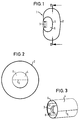
- a fabric part 4 is shown, with one on all sides closed pre-expansion chamber 6 is formed, which only after Opening the tear line 5 with the interior of the gas bag 2 in flow connection stands.
- a fabric part 4 is shown in FIG. 3, with a tube-like, at two ends to the interior of the gas bag 2 open pre-expansion chamber 6 is formed.
- an airbag After activation of the compressed gas source 3, the generated flows Pressurized gas first into the pre-expansion chamber 6. During the The pre-expansion chamber is filled (not in the figures illustrated) cover of the gas bag opened without the actual gas bag 2 is already pressurized with gas. Consequently there can be no chambers or bubbles underneath the cover, that could damage the wall of the gas bag. When a predetermined pressure inside the pre-expansion chamber 6 is reached, the tear line 5 is opened so that the interior of the Gas bags 2 are in flow connection with the compressed gas source 3 and the gas bag 2 will be filled completely.
- the fabric part 4 can either be sewn to the wall of the gas bag be or a separate part that is inserted into the gas bag 2 is. In this case, as shown in FIG. 3, fixed by means of the fastening screws 8 for the compressed gas source will.
Abstract
Description
Die Erfindung betrifft einen Gassack für ein Fahrzeuginsassen-Rückhaltesystem. Ein solches Rückhaltesystem besteht im wesentlichen aus einer Vorrichtung, die nach Aktivierung Druckgas bereitstellt, und einem Gassack, der ausgehend von einem zusammengefalteten, hinter einer Abdeckung verborgenen Ruhezustand mittels des Druckgases entfaltet werden kann, um bei einem Unfall eine Rückhaltewirkung für einen Fahrzeuginsassen bereitzustellen.The invention relates to an airbag for a vehicle occupant restraint system. Such a restraint system essentially exists from a device which provides compressed gas after activation, and a gas bag, starting from a folded, behind a cover hidden idle state by means of the compressed gas can be deployed to provide restraint for an accident to provide a vehicle occupant.
Gemäß der Erfindung ist ein Gassack mit einer Einblasöffnung und einem mit einer Reißlinie versehenen Gewebeteil geschaffen, das im Inneren des Gassacks gegenüber dessen Einblasöffnung angeordnet ist und eine Vorentfaltungs-Kammer bildet, die mit der Einblasöffnung in Strömungsverbindung steht. Wenn nach Aktivierung des Rückhaltesystems Druckgas in den Gassack einströmt, wird zuerst die Vorentfaltungs-Kammer gefüllt. Somit tritt der gefaltete Gassack kompakt aus der Abdeckung aus, und es können keine Kammern oder Blasen unterhalb der Abdeckung entstehen, die für das Austreten des Gassacks aus der Abdeckung nachteilig sein könnten. Sobald ein vorbestimmter Druck im Inneren der Vorentfaltungs-Kammer überschritten wird, reißt die Reißlinie auf, und der Gassack wird vollständig gefüllt. According to the invention is an airbag with an injection opening and a fabric part provided with a tear line, which in Inside of the gas bag is arranged opposite its blowing opening and forms a pre-deployment chamber that merges with the injection opening Flow connection is established. If after activation of the restraint system Compressed gas flows into the gas bag, the pre-expansion chamber is first filled. The folded airbag thus emerges compactly from the cover out, and there can be no chambers or bubbles below the Cover arise for the gas bag to emerge from the cover could be disadvantageous. As soon as a predetermined pressure in the If the inside of the pre-expansion chamber is exceeded, the tear line breaks and the gas bag is filled completely.
Weitere vorteilhafte Ausgestaltungen der Erfindung ergeben sich aus den Unteransprüchen.Further advantageous embodiments of the invention result from the subclaims.
Die Erfindung wird nachfolgend unter Bezugnahme auf verschiedene Ausführungsformen beschrieben, die in der Zeichnung dargestellt sind. In dieser zeigen:
- Fig. 1 einen schematischen Querschnitt durch einen erfindungsgemäßen Gassack;
- Fig. 2 eine schematische Ansicht entlang der Linie II-II von Figur 1; und
- Fig. 3 schematisch eine perspektivische Ansicht des im Inneren des Gassacks angeordneten Gewebeteils.
- 1 shows a schematic cross section through an airbag according to the invention;
- Fig. 2 is a schematic view along the line II-II of Figure 1; and
- Fig. 3 schematically shows a perspective view of the fabric part arranged in the interior of the gas bag.
In Figur 1 ist schematisch ein Fahrzeuginsassen-Rückhaltesystem 1
dargestellt, bei dem ein erfindungsgemäßer Gassack 2 verwendet wird.
Der Gassack 2 steht über seine Einblasöffnung in Strömungsverbindung
mit einer Druckgasquelle 3, die nach Aktivierung Druckgas bereitstellt,
um den Gassack 2 aus einem zusammengefalteten Ruhezustand zu
entfalten.1 schematically shows a vehicle occupant restraint system 1
shown, in which an airbag 2 according to the invention is used.
The gas bag 2 is in flow connection via its blowing opening
with a
Im Inneren des Gassacks 2 gegenüber der Einblasöffnung ist ein
Gewebeteil 4 angeordnet, das mit einer Reißlinie 5 versehen ist (siehe
Figuren 2 und 3). Das Gewebeteil 4 bildet eine Vorentfaltungs-Kammer
6.Inside the gas bag 2 opposite the blowing opening is a
Fabric part 4 arranged, which is provided with a tear line 5 (see
Figures 2 and 3). The fabric part 4 forms a
In Figur 2 ist ein Gewebeteil 4 dargestellt, mit dem eine allseitig
geschlossene Vorentfaltungs-Kammer 6 gebildet ist, die erst nach
Öffnen der Reißlinie 5 mit dem Innenraum des Gassacks 2 in Strömungsverbindung
steht. In Figur 3 ist dagegen ein Gewebeteil 4 dargestellt,
mit dem eine schlauchartige, an zwei Enden zum Innenraum des Gassacks
2 geöffnete Vorentfaltungs-Kammer 6 gebildet ist. In Figure 2, a fabric part 4 is shown, with one on all sides
closed pre-expansion
Die Arbeitsweise eines erfindungsgemäßen Gassacks ist die
folgende: Nach Aktivierung der Druckgasquelle 3 strömt das erzeugte
Druckgas zuerst in die Vorentfaltungs-Kammer 6 ein. Im Laufe des
Füllens der Vorentfaltungs-Kammer wird die (in den Figuren nicht
dargestellte) Abdeckung des Gassacks geöffnet, ohne daß der
eigentliche Gassack 2 bereits mit Druckgas beaufschlagt wird. Somit
können keine Kammern oder Blasen unterhalb der Abdeckung entstehen,
die zu einer Beschädigung der Wandung des Gassacks führen könnten.
Wenn ein vorbestimmter Druck im Inneren der Vorentfaltungs-Kammer 6
erreicht ist, wird die Reißlinie 5 geöffnet, so daß der Innenraum des
Gassacks 2 frei mit der Druckgasquelle 3 in Strömungsverbindung steht
und der Gassack 2 wird vollständig gefüllt wird.The operation of an airbag according to the invention is
following: After activation of the
Das Gewebeteil 4 kann entweder mit der Wandung des Gassacks vernäht
sein oder ein separates Teil sein, das in den Gassack 2 eingelegt
ist. In diesem Fall kann es, wie dies in Figur 3 dargestellt ist,
mittels der Befestigungsschrauben 8 für die Druckgasquelle festgelegt
werden.The fabric part 4 can either be sewn to the wall of the gas bag
be or a separate part that is inserted into the gas bag 2
is. In this case, as shown in FIG. 3,
fixed by means of the
Claims (5)
Applications Claiming Priority (2)
| Application Number | Priority Date | Filing Date | Title |
|---|---|---|---|
| DE29617486U | 1996-10-08 | ||
| DE29617486U DE29617486U1 (en) | 1996-10-08 | 1996-10-08 | Gas bag |
Publications (1)
| Publication Number | Publication Date |
|---|---|
| EP0835786A1 true EP0835786A1 (en) | 1998-04-15 |
Family
ID=8030298
Family Applications (1)
| Application Number | Title | Priority Date | Filing Date |
|---|---|---|---|
| EP97116722A Withdrawn EP0835786A1 (en) | 1996-10-08 | 1997-09-25 | Airbag |
Country Status (5)
| Country | Link |
|---|---|
| EP (1) | EP0835786A1 (en) |
| JP (1) | JPH10119681A (en) |
| KR (1) | KR19980032499A (en) |
| DE (1) | DE29617486U1 (en) |
| ES (1) | ES2117609T1 (en) |
Cited By (4)
| Publication number | Priority date | Publication date | Assignee | Title |
|---|---|---|---|---|
| EP1298015A2 (en) | 2001-09-28 | 2003-04-02 | Toyoda Gosei Co., Ltd. | Airbag device |
| US6585290B2 (en) | 2000-08-31 | 2003-07-01 | Delphi Technologies, Inc. | Diffuser for an air bag |
| FR2890022A1 (en) | 2005-09-01 | 2007-03-02 | Livbag Soc Par Actions Simplif | Tubular pyrotechnic gas generator for vehicle air bag, has sealed housing with transit chamber for temporary storage of part of combustion gas, and ducts, in communication with combustion chamber, to divide gas into two distinct flows |
| US7748739B2 (en) | 2006-06-27 | 2010-07-06 | Autoliv Asp, Inc. | Device for protecting an inflatable element |
Families Citing this family (7)
| Publication number | Priority date | Publication date | Assignee | Title |
|---|---|---|---|---|
| US5944342A (en) * | 1997-10-21 | 1999-08-31 | Trw Vehicle Safety Systems Inc. | Air bag with inflator shield |
| DE19962946A1 (en) * | 1999-12-24 | 2001-07-12 | Daimler Chrysler Ag | Airbag module has protective fabric layer that separates along preferred separation lines when gas escapes to form flaps that contact expanding airbag at edges of gas escape passage |
| JP4608072B2 (en) | 2000-02-25 | 2011-01-05 | タカタ株式会社 | Airbag device |
| DE102005021371A1 (en) * | 2005-05-04 | 2006-11-23 | Autoliv Development Ab | airbag |
| US7618060B2 (en) * | 2006-03-22 | 2009-11-17 | Trw Vehicle Safety Systems Inc. | Air bag module with an integral shield |
| DE102015202044A1 (en) * | 2015-02-05 | 2016-08-11 | Takata AG | Device for protecting gas bag fabric against escaping gas of a gas generator |
| DE102022100934A1 (en) | 2022-01-17 | 2023-07-20 | Zf Automotive Germany Gmbh | Leg air bag, vehicle and vehicle seat |
Citations (5)
| Publication number | Priority date | Publication date | Assignee | Title |
|---|---|---|---|---|
| US3586347A (en) * | 1969-06-05 | 1971-06-22 | Eaton Yale & Towne | Safety device |
| DE2152635A1 (en) * | 1971-10-22 | 1973-04-26 | Volkswagenwerk Ag | SAFETY DEVICE FOR VEHICLES |
| EP0496566A1 (en) * | 1991-01-22 | 1992-07-29 | Dowty Woodville Polymer Limited | A vehicle crash bag |
| DE4239035A1 (en) * | 1991-11-19 | 1993-05-27 | Trw Vehicle Safety Systems | |
| GB2265118A (en) * | 1992-03-18 | 1993-09-22 | Takata Corp | Vehicle air bag. |
-
1996
- 1996-10-08 DE DE29617486U patent/DE29617486U1/en not_active Expired - Lifetime
-
1997
- 1997-09-25 EP EP97116722A patent/EP0835786A1/en not_active Withdrawn
- 1997-09-25 ES ES97116722T patent/ES2117609T1/en active Pending
- 1997-10-02 KR KR1019970050870A patent/KR19980032499A/en not_active Application Discontinuation
- 1997-10-08 JP JP9276140A patent/JPH10119681A/en active Pending
Patent Citations (5)
| Publication number | Priority date | Publication date | Assignee | Title |
|---|---|---|---|---|
| US3586347A (en) * | 1969-06-05 | 1971-06-22 | Eaton Yale & Towne | Safety device |
| DE2152635A1 (en) * | 1971-10-22 | 1973-04-26 | Volkswagenwerk Ag | SAFETY DEVICE FOR VEHICLES |
| EP0496566A1 (en) * | 1991-01-22 | 1992-07-29 | Dowty Woodville Polymer Limited | A vehicle crash bag |
| DE4239035A1 (en) * | 1991-11-19 | 1993-05-27 | Trw Vehicle Safety Systems | |
| GB2265118A (en) * | 1992-03-18 | 1993-09-22 | Takata Corp | Vehicle air bag. |
Cited By (10)
| Publication number | Priority date | Publication date | Assignee | Title |
|---|---|---|---|---|
| US6585290B2 (en) | 2000-08-31 | 2003-07-01 | Delphi Technologies, Inc. | Diffuser for an air bag |
| EP1298015A2 (en) | 2001-09-28 | 2003-04-02 | Toyoda Gosei Co., Ltd. | Airbag device |
| EP1298015A3 (en) * | 2001-09-28 | 2004-05-06 | Toyoda Gosei Co., Ltd. | Airbag device |
| US6899352B2 (en) | 2001-09-28 | 2005-05-31 | Toyoda Gosei Co., Ltd | Airbag device |
| US7066490B2 (en) | 2001-09-28 | 2006-06-27 | Toyoda Gosei, Co., Ltd. | Airbag device |
| CN1318244C (en) * | 2001-09-28 | 2007-05-30 | 丰田合成株式会社 | Airbag device |
| FR2890022A1 (en) | 2005-09-01 | 2007-03-02 | Livbag Soc Par Actions Simplif | Tubular pyrotechnic gas generator for vehicle air bag, has sealed housing with transit chamber for temporary storage of part of combustion gas, and ducts, in communication with combustion chamber, to divide gas into two distinct flows |
| WO2007025963A1 (en) | 2005-09-01 | 2007-03-08 | Autoliv Development Ab | Pyrotechnic gas generator containing means for temporarily storing some of the gases |
| US8011302B2 (en) | 2005-09-01 | 2011-09-06 | Autoliv Development Ab | Pyrotechnic gas generator temporarily storing some gases |
| US7748739B2 (en) | 2006-06-27 | 2010-07-06 | Autoliv Asp, Inc. | Device for protecting an inflatable element |
Also Published As
| Publication number | Publication date |
|---|---|
| ES2117609T1 (en) | 1998-08-16 |
| DE29617486U1 (en) | 1997-02-13 |
| KR19980032499A (en) | 1998-07-25 |
| JPH10119681A (en) | 1998-05-12 |
Similar Documents
| Publication | Publication Date | Title |
|---|---|---|
| DE10316026B4 (en) | Degassing system for airbag | |
| DE69828681T2 (en) | AIRBAG DEVICE FOR SIDE IMPACT ON VEHICLES | |
| DE19742151B4 (en) | Side impact air bag system | |
| DE60214551T2 (en) | MODULAR AIRBAG FADING SYSTEM | |
| DE69912401T2 (en) | SIDE AIRBAG DEVICE | |
| DE60204516T2 (en) | Occupant protection device | |
| DE19848592B4 (en) | Airbag with shielding | |
| EP0714818B1 (en) | Side-impact air bag | |
| EP0858933B1 (en) | Knee bolster for a vehicle | |
| EP0800963B1 (en) | Air bag | |
| DE19720621A1 (en) | Pressure regulator for motorcycle airbag | |
| DE102010044677A1 (en) | Side airbag device | |
| DE19719151A1 (en) | Inflatable vehicle occupant protection device and method for inflating the device | |
| DE19714267A1 (en) | Side impact airbag system for motor vehicles | |
| DE69910124T2 (en) | Seat belt with inflatable chambers | |
| EP0835786A1 (en) | Airbag | |
| EP1412232B1 (en) | Occupant restraint system located in the rear passenger compartment of a motor vehicle | |
| DE19626761C1 (en) | Vehicle airbag system | |
| DE19750182C2 (en) | Airbag module with a drive for the cover flap | |
| DE4138645A1 (en) | Air-bag system for vehicle - uses given method of folding and storing empty bag | |
| EP0861760B1 (en) | Flexible air bag housing | |
| EP1048533A1 (en) | Vehicle passenger airbag protection device | |
| DE102004052462B4 (en) | airbag system | |
| DE4301193C2 (en) | Door training for a motor vehicle with an airbag | |
| DE69821356T2 (en) | AIRBAG INFLATION DEVICE OF THE SUCTION TYPE |
Legal Events
| Date | Code | Title | Description |
|---|---|---|---|
| PUAI | Public reference made under article 153(3) epc to a published international application that has entered the european phase |
Free format text: ORIGINAL CODE: 0009012 |
|
| AK | Designated contracting states |
Kind code of ref document: A1 Designated state(s): DE ES FR GB IT |
|
| AX | Request for extension of the european patent |
Free format text: AL;LT;LV;RO;SI |
|
| RAP1 | Party data changed (applicant data changed or rights of an application transferred) |
Owner name: TRW OCCUPANT RESTRAINT SYSTEMS GMBH & CO. KG |
|
| GBC | Gb: translation of claims filed (gb section 78(7)/1977) | ||
| EL | Fr: translation of claims filed | ||
| REG | Reference to a national code |
Ref country code: ES Ref legal event code: BA2A Ref document number: 2117609 Country of ref document: ES Kind code of ref document: T1 |
|
| AKX | Designation fees paid |
Free format text: DE ES FR GB IT |
|
| RBV | Designated contracting states (corrected) |
Designated state(s): DE ES FR GB IT |
|
| STAA | Information on the status of an ep patent application or granted ep patent |
Free format text: STATUS: THE APPLICATION IS DEEMED TO BE WITHDRAWN |
|
| 18D | Application deemed to be withdrawn |
Effective date: 19981016 |