EP0835697A1 - Rolling mills - Google Patents
Rolling mills Download PDFInfo
- Publication number
- EP0835697A1 EP0835697A1 EP97307052A EP97307052A EP0835697A1 EP 0835697 A1 EP0835697 A1 EP 0835697A1 EP 97307052 A EP97307052 A EP 97307052A EP 97307052 A EP97307052 A EP 97307052A EP 0835697 A1 EP0835697 A1 EP 0835697A1
- Authority
- EP
- European Patent Office
- Prior art keywords
- rolls
- roll
- rolling
- diameter
- portions
- Prior art date
- Legal status (The legal status is an assumption and is not a legal conclusion. Google has not performed a legal analysis and makes no representation as to the accuracy of the status listed.)
- Granted
Links
Images


Classifications
-
- B—PERFORMING OPERATIONS; TRANSPORTING
- B21—MECHANICAL METAL-WORKING WITHOUT ESSENTIALLY REMOVING MATERIAL; PUNCHING METAL
- B21B—ROLLING OF METAL
- B21B37/00—Control devices or methods specially adapted for metal-rolling mills or the work produced thereby
- B21B37/28—Control of flatness or profile during rolling of strip, sheets or plates
- B21B37/30—Control of flatness or profile during rolling of strip, sheets or plates using roll camber control
- B21B37/34—Control of flatness or profile during rolling of strip, sheets or plates using roll camber control by hydraulic expansion of the rolls
-
- B—PERFORMING OPERATIONS; TRANSPORTING
- B21—MECHANICAL METAL-WORKING WITHOUT ESSENTIALLY REMOVING MATERIAL; PUNCHING METAL
- B21B—ROLLING OF METAL
- B21B1/00—Metal-rolling methods or mills for making semi-finished products of solid or profiled cross-section; Sequence of operations in milling trains; Layout of rolling-mill plant, e.g. grouping of stands; Succession of passes or of sectional pass alternations
- B21B1/22—Metal-rolling methods or mills for making semi-finished products of solid or profiled cross-section; Sequence of operations in milling trains; Layout of rolling-mill plant, e.g. grouping of stands; Succession of passes or of sectional pass alternations for rolling plates, strips, bands or sheets of indefinite length
- B21B1/222—Metal-rolling methods or mills for making semi-finished products of solid or profiled cross-section; Sequence of operations in milling trains; Layout of rolling-mill plant, e.g. grouping of stands; Succession of passes or of sectional pass alternations for rolling plates, strips, bands or sheets of indefinite length in a rolling-drawing process; in a multi-pass mill
-
- B—PERFORMING OPERATIONS; TRANSPORTING
- B21—MECHANICAL METAL-WORKING WITHOUT ESSENTIALLY REMOVING MATERIAL; PUNCHING METAL
- B21B—ROLLING OF METAL
- B21B13/00—Metal-rolling stands, i.e. an assembly composed of a stand frame, rolls, and accessories
- B21B13/02—Metal-rolling stands, i.e. an assembly composed of a stand frame, rolls, and accessories with axes of rolls arranged horizontally
-
- B—PERFORMING OPERATIONS; TRANSPORTING
- B21—MECHANICAL METAL-WORKING WITHOUT ESSENTIALLY REMOVING MATERIAL; PUNCHING METAL
- B21B—ROLLING OF METAL
- B21B13/00—Metal-rolling stands, i.e. an assembly composed of a stand frame, rolls, and accessories
- B21B13/14—Metal-rolling stands, i.e. an assembly composed of a stand frame, rolls, and accessories having counter-pressure devices acting on rolls to inhibit deflection of same under load; Back-up rolls
-
- B—PERFORMING OPERATIONS; TRANSPORTING
- B21—MECHANICAL METAL-WORKING WITHOUT ESSENTIALLY REMOVING MATERIAL; PUNCHING METAL
- B21B—ROLLING OF METAL
- B21B13/00—Metal-rolling stands, i.e. an assembly composed of a stand frame, rolls, and accessories
- B21B13/02—Metal-rolling stands, i.e. an assembly composed of a stand frame, rolls, and accessories with axes of rolls arranged horizontally
- B21B2013/025—Quarto, four-high stands
-
- B—PERFORMING OPERATIONS; TRANSPORTING
- B21—MECHANICAL METAL-WORKING WITHOUT ESSENTIALLY REMOVING MATERIAL; PUNCHING METAL
- B21B—ROLLING OF METAL
- B21B27/00—Rolls, roll alloys or roll fabrication; Lubricating, cooling or heating rolls while in use
- B21B27/02—Shape or construction of rolls
- B21B27/021—Rolls for sheets or strips
- B21B2027/022—Rolls having tapered ends
-
- B—PERFORMING OPERATIONS; TRANSPORTING
- B21—MECHANICAL METAL-WORKING WITHOUT ESSENTIALLY REMOVING MATERIAL; PUNCHING METAL
- B21B—ROLLING OF METAL
- B21B2267/00—Roll parameters
- B21B2267/02—Roll dimensions
- B21B2267/06—Roll diameter
- B21B2267/065—Top and bottom roll have different diameters; Asymmetrical rolling
-
- B—PERFORMING OPERATIONS; TRANSPORTING
- B21—MECHANICAL METAL-WORKING WITHOUT ESSENTIALLY REMOVING MATERIAL; PUNCHING METAL
- B21B—ROLLING OF METAL
- B21B2275/00—Mill drive parameters
- B21B2275/02—Speed
- B21B2275/04—Roll speed
- B21B2275/05—Speed difference between top and bottom rolls
-
- B—PERFORMING OPERATIONS; TRANSPORTING
- B21—MECHANICAL METAL-WORKING WITHOUT ESSENTIALLY REMOVING MATERIAL; PUNCHING METAL
- B21B—ROLLING OF METAL
- B21B27/00—Rolls, roll alloys or roll fabrication; Lubricating, cooling or heating rolls while in use
- B21B27/02—Shape or construction of rolls
- B21B27/03—Sleeved rolls
- B21B27/05—Sleeved rolls with deflectable sleeves
Definitions
- the present invention relates to a rolling mill with laterally different velocities, that is to say a rolling mill including two opposed rolls whose diameter varies along their length.
- metal workpiece is rolled by passing it between a pair of upper and lower rolls in a rolling mill.
- the present invention was made in view of the above and has its object to provide a rolling mill with laterally different velocities which can apply rolling force on a workpiece with laterally different or uneven distribution and can readily adjust the distribution pattern during rolling operation, thereby substantially reducing occurrence of edge drop and crown on a rolled product in comparison with conventional different velocity rolling mills.
- the present invention provides a rolling mill with laterally different velocities which comprises a pair of rolls each having a barrel with different diameters axially of the barrel such that sum of the diameters of the barrels is substantially constant and that each of the rolls is bilaterally symmetrical, rotational velocity ratio of the rolls being changeable.
- Distribution pattern of the rolling force axially of the rolls is readily adjustable during rolling operation by changing rotational velocity ratio of the rolls. Occurrence of edge drop or crown on a rolled product can be reduced by adjusting the distribution pattern of the rolling force such that the rolling force is relatively increased at and near the opposite lateral edges of the workpiece and is relatively decreased at and near the lateral center of the workpiece.
- increased rolling force will increase elastic concave deformation of the roll, resulting in increase of the roll gap and thus increase in thickness of the workpiece.
- Decreased rolling force will decrease elastic concave deformation of the roll, resulting in decrease of the roll gap and thus decrease in thickness of the workpiece. Accordingly, when the rolling force is relatively increased at and near the lateral edges of the workpiece, the occurrence of edge drop can be decreased. When the rolling force is relatively decreased at and near the lateral center of the workpiece, occurrence of crown can be reduced.
- edge drop may be more serious than that of crown.
- Occurrence of crown may be more serious than that of edge drop.
- Profile control of workpiece may be desired in addition to prevention of crown or edge drop.
- consideration must be also given to change of roll over time since the roll may be thermally expanded in diameter at and near its axial center with lapse of time after the starting of rolling operation. Therefore, of course, distribution pattern of the rolling force must be adjusted in accordance with each individual case and roll change.
- the effect of decreasing the rolling force can be expected owing to different velocity rolling based on different or uneven distribution of roll diameter ratio of the rolls.
- Change of the rotational velocity ratio of the rolls into any value other than 1.0 will further enhance the effect of decreasing the rolling force, so that the level of the rolling force necessary for carrying out the rolling operation with the same rolling draft can be decreased as a whole.
- Such enhanced effect of decreasing the rolling force will enhance the effect of reducing occurrence of edge drop or crown.
- the different diameters of the roll barrels axially of them according to the invention may be provided such that the barrel of one of the rolls has largest diameter at its axial roll center and is convergent or gradually decreased in diameter toward opposite ends of said one roll and that the barrel of the other roll has the smallest diameter at its axial roll center and is divergent or gradually increased in diameter toward opposite ends of said other roll.
- Each of the rolls may have a parallel roll portion uniform in diameter at and near its axial roll center and may be supported at the very parallel roll portion by a backup roll.
- one of the rolls may have increased-diameter or divergent portions outwardly of its parallel portion toward the opposite ends of the one roll, the other roll having decreased-diameter or convergent portions outwardly of its parallel portion toward the opposite ends of the other roll.
- Each of the outwardly divergent and convergent portions contiguous with the central parallel portions of the barrels may additionally end with a further parallel portion at the corresponding roll end.
- the paired rolls may be contoured to have minute gaps between them at which the rolls are not mutually contacted upon application of light load and are mutually contacted upon application of rolling load.
- the present invention further provides a rolling mill with laterally different velocities which comprises a pair of rolls each having a barrel with axial, varied profile portions such that sum of the diameters of the barrels is substantially constant and that each of the rolls is bilaterally symmetrical with respect to axial roll center of the roll, at least one of the rolls being in the form of a profile variable roll whose counter may be partially varied during rolling operation.
- the profile variable roll may be a variable crown roll whose counter may be partially varied by selectively supply and discharging pressure fluid to and from fluid pressure chambers in the roll.
- the profile variable roll may be a tapered piston roll whose counter may be partially varied by displacing tapered pistons inside the roll.
- the varied profile portions of the roll barrel may be provided with fluid pressure chambers or tapered pistons for partial profile variation of the profile variable roll.
- the varied profile portions may be provided by mutually compensationally divergent and convergent portions of the rolls.
- a control unit may be provided to make one of the rolls partly divergent and make the other roll partly convergent correspondingly.
- a pair of rolls are used each of which has a barrel with axial, varied profile portions, the barrel being bilaterally symmetrical with respect to the axial roll center, sum of roll diameters of the barrels being substantially constant.
- Controlled profile amount can be adjusted by providing at least one of said paired rolls in the form of a profile variable roll to partially change the profile during rolling operation.
- a variable crown roll may be used whose profile can be partially changed by selectively supplying and discharging pressure fluid to and from fluid pressure chambers inside the roll.
- a tapered piston roll may be used whose profile can be partially changed by displacing tapered pistons inside the roll.
- the varied profile portions of the rolls may be provided by mutually compensational divergent and convergent portions of the rolls.
- a control unit may be provided to make one and the other of the rolls partly divergent and convergent mutually compensationally.
- the invention provides a rolling mill with laterally different velocities which comprises at least three rolls combined in pairs to form a plurality of rolling passes, the paired adjacent rolls each having a barrel which is bilaterally symmetrical with respect to axial roll center of the roll, sum of roll diameters of the barrels of the paired rolls being substantially constant, the barrels of one and the other of said paired rolls having mutually compensatory varied profile portions.
- the workpiece is passed sequentially through the rolling passes between the paired rolls from upstream to undergo laterally different velocity rolling a plurality of times.
- Such multi-pass rolling on the single rolling mill will allow the laterally different velocity rolling per rolling pass to be smaller in extent.
- the degree of profile variation of the varied profile portion can be decreased to prevent troubles such as streaking and bending of the workpiece on boundaries between the varied profile portions.
- Figs. 1 to 6 represent a first embodiment of a rolling mill with laterally different velocities according to the invention.
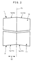
- a pair of upper and lower rolls 1 and 2 for rolling a workpiece 3 are rotatably supported at their ends by roll chocks 5 in a housing 6.
- Each of the rolls 1 and 2 is connected at its one end (right in Fig. 1) through universal couplings 7 and a spindle 8 to a separate rotating drive 9 so that rotational velocity ratio of the rolls 1 and 2 may be changed as desired.
- barrels 10 and 11 of the rolls 1 and 2 respectively comprise varied profile portions 13 and 14 with different diameters in axial direction 12 of the rolls such that sums of roll diameters of the portions 13 and 14 of the barrels 10 and 11 are substantially constant and that each of the rolls 1 and 2 is bilaterally symmetrical.
- the barrel 10 comprises outwardly convergent portions 16 each of which has largest diameter at axial roll center 15 and is gradually decreased in diameter toward a corresponding roll end; and the barrel 11 comprises outwardly divergent portions 17 each of which has smallest diameter at the roll center 15 and is gradually increased in diameter toward a corresponding roll end.
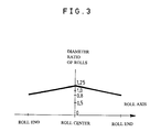
- the barrels 10 and 11 have axially different or uneven distribution of roll diameter ratio as shown in Fig. 3.
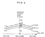
- Rotation of the rolls 1 and 2 in the above arrangement will cause peripheral velocity ratio of the barrels 10 and 11 of the rolls 1 and 2 to have different or uneven distribution in the axial direction 12. More specifically, as shown in Fig. 4, with rotational velocity ratios of the rolls 1 and 2 (i.e. ratios of rotational velocity of the upper roll 1 to rotational velocity of the lower roll 2) being 1.25, 1.0 and 0.8, the results are as shown by A1, B1 and C1, respectively.
- This distribution pattern of the different velocity rate X is closely related with the distribution pattern of rolling force laterally of the workpiece 3 (axially of the rolls 1 and 2). There is a tendency such that, when the different velocity rate X is high, rolling force is decreased, and when the different velocity rate X is low, rolling force is increased.
- distribution pattern of rolling force laterally of the workpiece 3 is as shown by A3, B3 and C3 with the rotational velocity ratios of the rolls 1 and 2 being 1.25, 1.0 and 0.8, respectively.
- the rolling force can be applied with different or uneven distribution in the axial direction 12 of the rolls 1 and 2 when the workpiece 3 is rolled between the rolls. Moreover, distribution pattern of the rolling force can be readily changed laterally of the workpiece 3 during rolling operation by changing the rotational velocity ratio of the rolls 1 and 2.
- the distribution pattern of the rolling force may be adjusted by rotational velocity ratio of the rolls such that, as shown by A3 in Fig. 6, rolling force is relatively increased at and near the lateral edges of the workpiece 3 (i.e., at and near the ends of the rolls 1 and 2) and is relatively decreased at and near the lateral center of the workpiece 3 (i.e., at and near the axial roll center 15 of the rolls 1 and 2), which can reduce the occurrence of edge drop and crown.
- Occurrence of edge drop may be more serious than that of crown.
- Occurrence of crown may be more serious than that of edge drop.
- Profile control of workpiece 3 may be desired in addition to prevention of crown or edge drop.
- consideration must be also given to change of roll over time since the roll may be thermally expanded in diameter at and near its axial center 15 with lapse of time after the starting of rolling operation. Therefore, of course, distribution pattern of the rolling force must be adjusted in accordance with each individual case and roll change.
- the distribution pattern of the rolling force shown by A3 in Fig. 6 is not necessarily optimal.
- the distribution pattern of the rolling force shown by B3 in Fig. 6 is effective to a case where the workpiece 3 is locally thinner in thickness at an intermediate position between the lateral center and the edge of the workpiece and has poorer flatness and defective profile.
- the distribution pattern of the rolling force shown by C3 in Fig. 6 is effective to a case where each of the rolls 1 and 2 has increased diameter at and near the roll center 15 due to thermal expansion.
- the effect of reducing the rolling force can be expected owing to different velocity rolling based on the different or uneven distribution of roll diameter ratio of the rolls.
- Change of the rotational velocity ratio of the rolls into any value other than 1.0 will further enhance the effect of decreasing the rolling force, so that the rolling force necessary for carrying out the rolling operation with the same rolling draft can be decreased as a whole.
- Such enhanced effect of decreasing the rolling force will enhance the effect of reducing occurrence of edge drop or crown.
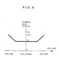
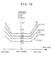
- Figs. 7 to 12 represent a second embodiment of the invention in which the barrels 10 and 11 of the rolls 1 and 2 have parallel portions 18 and 19 at and near the roll center 15 which have no change in diameter or no profile change and at which the rolls 1 and 2 are supported by backup rolls 20 and 21, respectively.
- divergent portions 22 each having diameter gradually increased toward the corresponding roll end are provided outwardly of the parallel portion 18 of the barrel 10 of the upper roll 1; and convergent portions 23 each having diameter gradually reduced toward the corresponding roll end are provided outwardly of the parallel portion 19 of the barrel 10 of the lower roll 2.
- Fig. 7 for facilitation in understanding of the profile of the rolls 1 and 2, the diameters of the rolls 1 and 2 are shown in exaggeration with respect to diameters of the backup rolls 20 and 21. In fact, the sizes of the rolls 1 and 2 can be reduced than they are conjectured from the figure.
- This embodiment has distribution of the roll diameter ratio as shown in Fig. 9.
- peripheral velocity ratio on the barrels 10 and 11 of the rolls 1 and 2 has uneven distribution axially of the rolls. More specifically, as shown in Fig. 10, with the rotational velocity ratio of the rolls 1 and 2 being 1.2, 1.0, 0.8 and 0.6, the results are as shown by A1, B1, C1 and D1, respectively.
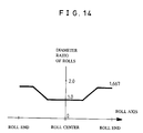
- Figs. 13 to 17 represents a third embodiment of the present invention in which further parallel portions 24 and 25 are provided at and near the roll ends of the rolls 1 and 2 in the embodiment shown in Fig. 7 as described above. More specifically, divergent portions 22 each having diameter gradually increased toward the corresponding roll end are provided outwardly of the parallel portion 18 of the barrel 10 of the upper roll 1 and end with further parallel portions 24 each having no change in diameter at and near the corresponding roll end. Also, convergent portions 23 each having diameter gradually decreased toward the corresponding roll end are provided outwardly of the parallel portion 19 of the barrel 11 of the lower roll 2 and end with further parallel portions 25 each having no change in diameter at and near the corresponding roll end.
- This embodiment has distribution of the roll diameter ratio as shown in Fig. 14.
- peripheral velocity ratio on the barrels 10 and 11 of the rolls 1 and 2 shows different or uneven distribution axially of the rolls. More specifically, the results are as shown by A1, B1, C1 or D1 in Fig. 15 with the rotational velocity ratio of the rolls 1 and 2 being 1.2, 1.0, 0.8 and 0.6, respectively.
- Diameter difference is given to the barrels 10 and 11 of the paired rolls 1 and 2 to provide the varied profile portions 13 and 14 such that sum of roll diameters of the axially portions 13 and 14 of the barrels 10 and 11 is substantially constant and that each of the rolls 1 and 2 is bilaterally symmetrical, the rotational velocity ratio of the rolls 1 and 2 being changeable.
- the rolling force applied on the workpiece 3 has different or uneven distribution axially of the rolls and the distribution pattern can be readily controlled during rolling operation by changing the rotational velocity ratio of the rolls 1 and 2. Accordingly, rolling operation can be performed with distribution pattern of the rolling force suitable for reducing the occurrence of edge drop and crown.
- change of the rotational velocity ratio of the rolls 1 and 2 into any value other than 1.0 will enhance the effect of reduce the rolling force in normal different velocity rolling, so that the level of the rolling force necessary for rolling operation can be decreased as a whole. This makes it possible to substantially reduce occurrence of edge drop or crown in comparison with conventional different velocity rolling mills.
- Fig. 18 shows a fourth embodiment of the invention which is a variation of the first embodiment described above.
- paired rolls 1 and 2 have barrels 10 and 11 contoured to have minute gaps 26 between the varied profile portions 13 and 14 of the barrels 10 and 11 at which the rolls 1 and 2 are not mutually contacted upon application of light load and are mutually contacted upon application of rolling load.
- the minute gaps 26 are in the order of several millimeters or less and are within such range that sum of roll diameters of the barrels is substantially constant.
- the barrel 10 of the upper roll 1 in Fig. 18 comprises only convergent portions 16 each having diameter gradually reduced from the roll center 15 toward the corresponding roll end.
- the barrel 11 of the lower roll 2 comprises only divergent portions 17 each having diameter gradually increased from the roll center 15 toward the corresponding roll end. Between the convergent and divergent portions 16 and 17, the minute gaps 16 gradually enlarged from the roll center 15 toward the roll ends are formed.
- the minute gaps 16 gradually enlarged toward the roll ends are provided between the convergent and divergent portions 22 and 23, the minute gaps 16 prevent the barrel portions having peripheral velocity difference due to diameter difference from being mutually contacted when light load is applied for zeroing. This prevents vibration or seizure due to zeroing.
- This embodiment has the same arrangement as in the second embodiment except the above and can attain the same operation and effects as those in the second embodiment.
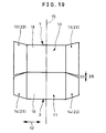
- Fig. 19 shows a fifth embodiment of the invention which is a variation of the second embodiment described above.
- paired rolls 1 and 2 have barrels 10 and 11 contoured to have minute gaps 26 between the varied profile portions 13 and 14 of the barrels 10 and 11 at which the rolls 1 and 2 are not mutually contacted upon application of light load and are mutually contacted upon application of rolling load.
- the minute gaps 26 are in the order of several millimeters or less and are within such range that sum of roll diameters of the barrels is substantially constant.
- the barrel 10 of the upper roll 1 in Fig. 19 comprises a parallel portion 18 at and near the roll center 15 and divergent portions 16 contiguous with the portion 18 and each having diameter gradually increased toward the corresponding roll end.
- the barrel 11 of the lower roll 2 comprises a parallel portion 19 at and near the roll center 15 and having the same diameter as that of the parallel portion 18, and convergent portions 17 contiguous with the portion 19 and each having diameter gradually increased from the roll center 15 toward the corresponding roll end. Between the convergent and divergent portions 16 and 17, the minute gaps 16 gradually enlarged from the roll center 15 toward the roll ends are formed.
- the minute gaps 16 gradually enlarged toward the roll ends are provided between the convergent and divergent portions 22 and 23, the minute gaps 16 prevent the barrel portions having peripheral velocity difference due to diameter difference from being mutually contacted when light load is applied for zeroing. This prevents vibration or seizure due to zeroing.
- This embodiment has the same arrangement as in the second embodiment except the above and can attain the same operation and effects as those in the second embodiment.
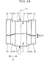
- Fig. 20 shows a sixth embodiment of the invention which is a variation of the third embodiment as described above.
- paired rolls 1 and 2 have barrels 10 and 11 contoured to have minute gaps 26 between the varied profile portions 13 and 14 of the barrels 10 and 11 at which the rolls 1 and 2 are not mutually contacted upon application of light load and are mutually contacted upon application of rolling load.
- the minute gaps 26 are in the order of several millimeters or less and are within such range that sum of roll diameters of the barrels is substantially constant.
- the barrel 10 of the upper roll 1 in Fig. 20 comprises a parallel portion 18 at and near the roll center 15 and divergent portions 22 contiguous with the parallel portion 18 and each having diameter gradually increased from the roll center 15 toward the corresponding roll end.
- the divergent portion 22 ends, at the corresponding roll end, with larger-diameter parallel portions 24.
- the barrel 11 of the lower roll 2 comprises a parallel portion 19 at and near the roll center 15 and having the same diameter as that of the parallel portion 18 and convergent portions 23 contiguous with the parallel portion 19 and each having diameter gradually increased from the roll center 15 toward the corresponding roll end.
- the convergent portion 23 ends, at the corresponding roll end, with smaller-diameter parallel portions 25.
- minute gaps 26 gradually enlarged from the roll center 15 toward the roll ends are formed. Further, between the larger- and smaller-diameter parallel portions 24 and 25, minute gaps 27 are formed which are contiguous with the minute gaps 26 and have constant width.
- the minute gaps 26 gradually enlarged toward the roll ends are provided between the divergent and convergent portions 22 and 23 and the minute gaps 27 having constant width are provided between the larger- and smaller-diameter parallel portions 24 and 25, the minute gaps 26 and 27 prevent the barrel portions having peripheral velocity difference due to diameter difference from being mutually contacted when light load is applied for zeroing. This prevents vibration or seizure due to zeroing.
- This embodiment has the same arrangement as in the third embodiment except the above and can attain the same operation and effects as those in the third embodiment.
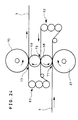
- Figs. 21 and 22 represent a seventh embodiment of the present invention.
- This embodiment may also be applied to the different velocity rolling mill of the type shown in Fig. 13 or any other different velocity rolling mills.
- This embodiment resides in that at least one of a pair of rolls 1 and 2 is in the form of a profile variable roll (both in Fig. 21; see the parts 28 and 29) with the profile changeable during rolling operation.
- the profile variable rolls 28 and 29 may be variable crown rolls (so-called VC rolls) which respectively comprise roll sleeves 32 and 33 serving as the barrels 10 and 11 and shrinkage- or cooling-fitted to outer peripheries of roll shafts 30 and 31 supported by roll chocks 5, annular fluid pressure chambers 34 and 35 between the roll shafts 30 and 31 and the roll sleeves 32 and 33.
- Outer profiles of the fluid pressure chambers 34 and 35 are changed by selectively supplying and discharging pressure fluid to and from the fluid pressure chambers 34 and 35, respectively.
- Reference numerals 36 and 37 represent closing members to close the fluid pressure chambers 34 and 35, respectively.
- the fluid pressure chambers 34 and 35 of the profile variable rolls 28 and 29 are provided at positions of varied profile portions 13 and 14 such as the divergent and convergent portions 22 and 23 of the rolls 1 and 2.
- varied profile portions 13 and 14 such as the divergent and convergent portions 22 and 23 of the rolls 1 and 2.
- the roll sleeve 32 of the upper roll 1 end with parallel (or divergent or convergent) portions 38 as shown by solid lines when the fluid pressure chamber 34 is not supplied with pressure fluid.
- the roll sleeve 32 is increased in diameter at its ends to provide divergent portions 22 as shown by two-dot chain lines.
- the roll sleeve 33 of the lower roll 2 end with convergent portions 39 as shown by solid lines when the fluid pressure chamber 35 is not supplied with pressure fluid.
- the roll sleeve 33 is increased in diameter at their ends to provide parallel (or divergent or convergent) portions 39 as shown by two-dot chain lines.
- the fluid pressure chambers 34 and 35 of the profile variable rolls 28 and 29 may be provided at positions other than the varied profile portions 13 and 14, i.e. at positions of the parallel portions 18 and 19 so as to change the profiles of the parallel portions 18 and 19.
- fluid pressure chambers 34 and 35 of the profile variable rolls 28 and 29 may be provided to some or all of the varied profile portions 13 and 14.
- the roll shafts 30 and 31 have fluid passages 40 and 41 for communication of the fluid pressure chambers 34 and 35 with ends of the roll shafts 30 and 31, respectively.
- Rotary joints 42 and 43 are mounted on such ends of the roll shafts 30 and 31, and changeover valves 47 and 48 are provided to switch to the supply of pressure fluid from pumps 44 and 45 to the fluid pressure chambers 34 and 35 or to the discharge of pressure fluid from the fluid pressure chambers 34 and 35 to a tank 46 via the fluid passages 40 and 41 and the rotary joints 42 and 43, respectively.
- a control unit 53 is provided to control such that, based on an input signal 50 from an input unit 49, switching signals 51 and 52 are sent to the changeover valves 47 and 48 to increase diameter of the fluid pressure chambers 34 and 35 of one of the rolls (1, 2) and to reduce diameter of the fluid pressure chambers 35 and 34 of the other roll (2, 1).
- an input signal 50 is sent to the control unit 53 by operating the input unit 49, and switching signals 51 and 52 corresponding to the input signal 50 are sent from the control unit 53 to the changeover valves 47 and 48 in order to switch over the valves properly.
- pressure fluid is supplied from the pumps 44 and 45 to the fluid pressure chambers 34 and 35 via the fluid passages 40 and 41 and the rotary joints 42 and 43 or discharged from the fluid pressure chambers 34 and 35 to the tank 46 so that diameter of the fluid pressure chambers 34 or 35 (i.e.
- an input signal 50 is sent to the control unit 53 by operating the input unit 49, and the changeover valves 47 and 48 are temporarily changed over to "b" side and "d” side by the switching signals 51 and 52 from the control unit 53.
- the divergent and convergent portions 22 and 23 are changed in profile during rolling operation to change the different velocity rate of and thus the rolling force of the portions 22 and 23 so that the profile control amount to the workpiece 3 can be changed.
- the profile control amount to the workpiece 3 is to be changed by controlling the rotational velocity ratio of the rolls 1 and 2, different velocity ratio of the whole rolls 1 and 2 including the central parallel portions 18 and 19 is changed, and the rolling force is extensively changed. Therefore, adjustment of the roll gap 4 is required, which causes difficulty.
- the profile variable rolls 28 and 29 are used to partially change the different velocity ratio, which contributes to controlling the change of the rolling force as a whole to lower value. Therefore, adjustment of the roll gap 4 is not required and profile control amount can be readily changed.
- the profile control amount may also be readily changed by providing the fluid pressure chambers 34 and 35 of the profile variable rolls 28 and 29 at positions other than the varied profile portions 13 and 14, i.e., at the parallel portions 18 and 19 and changing the profiles of the parallel portions 18 and 19 during rolling operation.
- each of the rolls 1 and 2 comprises two or more varied profile portions 13 or 14
- the profile control amount may also be readily changed by providing the fluid pressure chambers 34 and 35 of the profile variable rolls 28 and 29 to some or all of the varied profile portions 13 and 14 and partially changing the profiles.
- the laterally different velocity rolling mill according to the invention is more effective when it is used for the so-called temper rolling or skin pass rolling.
- temper rolling cold rolling with reduction of about 0.5-4% is performed on a workpiece 3, which has been annealed after cold rolling, in order to prevent coil break or stretcher strain, to give required mechanical properties, to improve the profile into flatness and to finish the product with proper surface roughness suitable for usage.
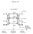
- Fig. 22 is a diagram which shows the above more concretely. Positions on the rolls 1 and 2 are plotted on abscissa, and rolling force is plotted on ordinate, with the rotational velocity ratio of the rolls 1 and 2 being changed.
- the line ⁇ shows pressure distribution in a case where a rotational velocity of the parallel portion 18 of the upper roll 1 is equal with that of the parallel portion 19 of the lower roll 2, i.e., in a case where the rotational velocity ratio of the rolls 1 and 2 is 1.0.
- the line ⁇ represents pressure distribution in a case where the rotational velocity of the parallel portion 18 of the upper roll 1 is increased to a value slightly higher than a rotational velocity of the parallel portion 19 of the lower roll 2, e.g., in a case where the rotational velocity ratio is 1.2.
- the line ⁇ represents pressure distribution in a case where the rotational velocity of the parallel portion 18 of the upper roll 1 is decreased to a value slightly lower than that of the parallel portion 19 of the lower roll 2, e.g., in a case where the rotational velocity ratio is 0.8.
- solid lines represent rolling force distribution when rolling is performed with the divergent and convergent portions 22 and 23 of the rolls 1 and 2 being set to predetermined standard profiles.
- One-dot chain lines show changes when the divergent and convergent portions 22 are respectively increased and decreased in diameter in comparison with the standard profiles during rolling operation.
- Two-dot chain lines show change when the divergent and convergent portions 22 and 23 are respectively decreased and increased in diameter in comparison with the standard profiles during rolling operation.
- the rolling force is at the highest on the parallel portions 18 and 19 rotated at equal velocity as shown by solid line, and is decreased toward the opposite ends of the divergent and convergent portions 22 and 23 since the peripheral velocity difference is increased toward the opposite ends of the portions 22 and 23.
- the divergent portions 22 of the roll 1 are increased in diameter to profiles greater than the standard profiles and the convergent portions 23 of the rolls 2 are decreased in diameter to profiles smaller than the standard profiles, the rolling force at the opposite ends is decreased as shown by one-dot chain lines since the peripheral velocity difference between the divergent and convergent portions 22 and 23 is increased more than the case shown by the solid line.
- the profile control amount can be adjusted by changing the profiles of the rolls 1 and 2.
- the rolling force is generally decreased in comparison with the case of the lines ⁇ .
- the divergent portions 22 are increased in diameter to profiles greater than the standard profiles and the convergent portions 23 are decreased in diameter to profiles smaller than the standard profiles, the rolling force at the opposite ends is decreased as shown by one-dot chain lines since peripheral velocity difference between the divergent and convergent portions 22 and 23 is increased in comparison with the case shown by solid line.
- the profile control amount can be adjusted by changing the profiles of the rolls 1 and 2.
- the rolling force is the lowest on the parallel portions 18 and 19 having peripheral velocity difference; and toward the opposite ends of the divergent and convergent portions 22 and 23, the rolling force is firstly increased and then is decreased sine peripheral velocity difference toward the opposite ends is firstly decreased, becomes zero and then is increased.
- the rolling force at the opposite ends is decreased as shown by one-dot chain lines since peripheral velocity difference between the divergent and convergent portions 22 and 23 is decreased in comparison with the case shown by the solid line.
- Fig. 23 represents an eighth embodiment of the invention in which profile variable rolls 28 and 29 are provided such that tapered annular pistons 56 and 57 are placed in tapered annular spaces 54 and 55 defined between roll shafts 30 and 31 and roll sleeves 32 and 33, respectively.
- Pressure fluid is selectively supplied and discharged to and from fluid pressure chambers 58-61 on opposite sides of the pistons 56 and 57 via fluid passages 62-65 and changeover valves 66 and 66'.
- the tapered pistons 56 and 57 are moved, and by placing them or withdrawing them from the tapered spaces 54 and 55, profiles of the rolls 1 and 2 can be changed.
- tapered piston rolls 28 and 29 are used instead of the profile variable rolls 28 and 29.
- the profile control amount to the workpiece 3 can be changed by changing the profiles of the rolls 1 and 2 during rolling operation as in the embodiments described above.
- This embodiment has the same arrangement as the above embodiments except the above points, and the same operation and the same effects can be provided.
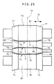
- Figs. 24 and 25 represent a ninth embodiment of the present invention.
- three or more rolls 67 to 70 are combined together (in vertical direction in the figure, though the rolls may be arranged not only in vertical direction but also in horizontal direction, in inclined direction or in zigzag manner) to provide a plurality of rolling passes 71-73.
- Pairs of the rolls 67 to 70 adjacent to each other to provide the rolling passes 71 to 73 have barrels each of which is bilaterally symmetrical with respect to the roll center 15, sum of roll diameters of the paired barrels being substantially constant.
- one of the paired barrel has varied profile portions 74-76 such as divergent or convergent portions and the other of the paired barrels have varied profile portions 75-77 such as divergent or convergent portions at positions corresponding to the above-mentioned divergent or convergent portions of the one of the paired barrels.
- a parallel portion 78 having uniform diameter is formed at the center of the barrel of the roll 67 at the lowest position, and divergent portions with diameter increasing toward the ends are formed on each end of the barrel as a varied profile portion 74.
- a parallel portion 79 having a diameter smaller than that of the parallel portion 78 is formed, and convergent portions having diameter decreasing toward the ends are formed on opposite ends of the barrel as varied profile portions 75. It is designed such that sum of diameters of the divergent and convergent portions which constitute the varied profile portions 74 and 75 is substantially equal to sum of diameters of the parallel portions 78 and 79.
- a parallel portion 80 having the same diameter as that of the parallel portion 79 is formed, and divergent portions having diameter increasing toward the ends are formed on opposite ends of the barrel as varied profile portions 76. It is designed such that sum of diameters of the divergent and convergent portions which constitute the varied profile portions 75 and 76 is substantially equal to sum of diameters of the parallel portions 79 and 80.
- a parallel portion 81 having a diameter larger than that of the parallel portion 80 is formed, and divergent portions having diameter decreasing toward the ends are formed on opposite ends of the barrel as varied profile portions 77. It is designed such that sum of diameters of the divergent and convergent portions which constitute the varied profile portions 76 and 77 is substantially equal to sum of diameters of the parallel portions 80 and 81.
- reference numerals 82 and 83 represent tension adjusters between the rolling passes 71-73.
- the workpiece 3 is passed through the rolling pass 71 formed by the rolls 67 and 68, through the rolling pass 72 formed by the rolls 68 and 69, and through the rolling pass 73 formed by the rolls 69 and 70 in this order from upstream side, and laterally different velocity rolling is performed by a plurality of times.
- multi-pass rolling is performed on a single rolling mill, which makes it possible to decrease the effect of laterally different velocity rolling per each of the rolling passes 71-73.
- the degree of the profile change of the varied profile portions 74-77 can be decreased (i.e., the tapered shape can be decreased). This makes it possible to prevent streaking, bending, etc. of the workpiece 3 at the boundaries between the varied profile portions 74-77 and the parallel portions 78-81.
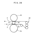
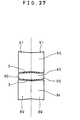
- Figs. 26 and 27 represent a tenth embodiment of the present invention.
- Three rolls 84 to 86 are combined together to form two rolling passes 87 and 88.
- the rolls 84-86 have no parallel portions and comprise only varied profile portions 89-91.
- This embodiment has the same arrangement as the above embodiments, and the same operation and the same effects can be provided.
- the rolling mill with laterally different velocities according to the present invention is not limited to the above embodiments. Basically, it is desirable that it is used for the purpose of reducing occurrence of edge drop or crown, while it is needless to say that it may be used mainly for the purpose of achieving profile control of the workpiece, that the roll may have any profile as far as the requirements for laterally different velocity rolling are satisfied, that any combination other than the above embodiments is also achievable, and further, that modifications and changes can be made without departing from the spirit and the scope of the present invention.
Landscapes
- Engineering & Computer Science (AREA)
- Mechanical Engineering (AREA)
- Reduction Rolling/Reduction Stand/Operation Of Reduction Machine (AREA)
- Metal Rolling (AREA)
Abstract
Description
when V1/V2 ≧ 1,
when V1/V2 < 1,
Claims (12)
- A rolling mill including two opposed rolls (1; 2), each of which is connected to rotational drive means (9) and the opposed surfaces of which are afforded by respective barrels (10, 11), the drive means (9) being arranged to vary the rotational velocity ratio of the two rolls, characterised in that the diameter of the barrels (10, 11) varies along at least part of their length, that the sum of the diameters of the two barrels at each position along their length is substantially constant and that each barrel (10, 11) is symmetrical about its longitudinal centre (15).
- A rolling mill as claimed in Claim 1, wherein the barrel (10) of one of the rolls (1) has its largest diameter at its longitudinal centre (15) and the diameter progressively decreases from the centre towards its two ends, and the barrel (11) of the other roll (2) has its smallest diameter at its longitudinal centre (15) and the diameter progressively increases from the centre towards its two ends.
- A rolling mill as claimed in Claim 1, wherein the central portions (18, 19) of the barrels (10, 11) are parallel sided with no change in diameter, and a backup roll (20, 21) is provided for each of the rolls (1, 2) to support it at the parallel sided portion (18, 19).
- A rolling mill as claimed in Claim 3 further comprising divergent portions (22) contiguous with the parallel portion (18) of the barrel (10) of one of the rolls (1) at each end thereof, the diameter of which progressively increases towards the associated roll end, and convergent portions (23) contiguous with the parallel portion (19) of the barrel (1 1) of the other roll (2) at each end thereof, the diameter of which progressively decreases towards the associated roll end.
- A rolling mill as claimed in Claim 4, comprising a further respective parallel sided portion (24, 25) contiguous with each divergent portion (22) and convergent portion (23) and extending outwardly therefrom to the associated roll end.
- A rolling mill as claimed in any one of Claims 1 to 5, wherein minute gaps are formed between those opposed portions (13, 14) of the barrels (10, 11) of the rolls (1, 2) whose diameter varies along their length, whereby the said portions (13, 14) do not contact one another when a light load is applied but do contact one another when a rolling load is applied.
- A rolling mill as claimed in any one of the preceding claims, wherein at least one of the rolls (1, 2) constitutes a variable profile roll (28, 29) whose peripheral contour may be partially varied during rolling operation.
- A rolling mill as claimed in Claim 7, wherein the or each variable profile roll is a variable crown roll (28, 29) in which fluid pressure chambers (34, 35) are formed and whose profile may be changed by selectively supplying and discharging fluid under pressure to and from the fluid pressure chambers.
- A rolling mill as claimed in Claim 7, wherein the or each profile variable roll is a tapered piston roll (28, 29), arranged within which are tapered pistons (56, 57) and whose profile may be changed by selective movement of the tapered pistons arranged inside.
- A rolling mill as claimed in Claim 8 or 9, wherein the fluid pressure chambers (34, 35) or tapered pistons (56, 57) are provided within those portions of the barrels (10, 11) whose diameter varies along their length.
- A rolling mill as claimed in any one of Claims 7 to 10 in which both rolls (1, 2) are variable profile rolls (28, 29) and further comprise a control unit (53) which is so arranged that when the diameter of a portion of one of the rolls (28) is increased the diameter of the opposing portion of the other roll (29) is complementarily decreased.
- A rolling mill comprising three or more rolls (78, 79, 80, 81; 84, 85, 86) cooperating in opposed pairs to define two or more rolling passes (71, 72, 73; 87, 88), each opposed pair of rolls being as claimed in any one of the preceding claims.
Applications Claiming Priority (12)
| Application Number | Priority Date | Filing Date | Title |
|---|---|---|---|
| JP24046396 | 1996-09-11 | ||
| JP240463/96 | 1996-09-11 | ||
| JP24046396 | 1996-09-11 | ||
| JP5182797 | 1997-03-06 | ||
| JP51827/97 | 1997-03-06 | ||
| JP05182797A JP3740778B2 (en) | 1996-09-11 | 1997-03-06 | Different speed rolling mill for sheet |
| JP7340397 | 1997-03-26 | ||
| JP73403/97 | 1997-03-26 | ||
| JP9073403A JPH10263623A (en) | 1997-03-26 | 1997-03-26 | Width direction different speed rolling mill |
| JP198801/97 | 1997-07-24 | ||
| JP19880197 | 1997-07-24 | ||
| JP9198801A JPH1133607A (en) | 1997-07-24 | 1997-07-24 | Rolling mill having different speed in width direction |
Publications (3)
| Publication Number | Publication Date |
|---|---|
| EP0835697A1 true EP0835697A1 (en) | 1998-04-15 |
| EP0835697B1 EP0835697B1 (en) | 2000-05-31 |
| EP0835697B2 EP0835697B2 (en) | 2004-12-08 |
Family
ID=27462696
Family Applications (1)
| Application Number | Title | Priority Date | Filing Date |
|---|---|---|---|
| EP97307052A Expired - Lifetime EP0835697B2 (en) | 1996-09-11 | 1997-09-11 | Rolling mills |
Country Status (4)
| Country | Link |
|---|---|
| US (1) | US6065319A (en) |
| EP (1) | EP0835697B2 (en) |
| CN (1) | CN1241690C (en) |
| DE (1) | DE69702173T3 (en) |
Families Citing this family (11)
| Publication number | Priority date | Publication date | Assignee | Title |
|---|---|---|---|---|
| CN102000698A (en) * | 2010-09-16 | 2011-04-06 | 南京钢铁股份有限公司 | Method for eliminating fierce collision of slab head on mill roller table through medium plate mill |
| CN102989765B (en) * | 2012-12-25 | 2015-06-17 | 东北大学 | Multifunctional rolling mill for producing thin metal straps and ultra-thin metal straps |
| CN105149384B (en) * | 2015-05-27 | 2018-11-16 | 南通超力卷板机制造有限公司 | Two roller differential variable curvature numerical control plate bending rolls and its application method |
| CN105107840B (en) * | 2015-08-06 | 2017-05-31 | 上海应用技术学院 | Magnesium alloy plate surface drastic deformation rolling device and method |
| JP6455498B2 (en) | 2016-11-16 | 2019-01-23 | トヨタ自動車株式会社 | Electrode plate manufacturing apparatus, positive electrode plate manufacturing method, and negative electrode plate manufacturing method |
| CN108296315A (en) * | 2018-05-11 | 2018-07-20 | 鞍钢股份有限公司 | A kind of method for aligning and straightening roll of flat-bulb steel |
| CN109396184B (en) * | 2018-11-20 | 2020-03-31 | 林旭娜 | Two-roller triangular rolling mill for manufacturing copper strip by using oxygen-free copper rod, production line and production process |
| CN110252817B (en) * | 2019-07-31 | 2020-02-07 | 深圳市铭匠模具有限公司 | Extrusion forming die |
| CN111789276A (en) * | 2020-07-31 | 2020-10-20 | 盐城工学院 | Green soy bean decorticator |
| CN113477707A (en) * | 2021-07-15 | 2021-10-08 | 太原理工大学 | Asynchronous micro-flexible rolling method for laminated metal composite thin strip |
| CN117772795B (en) * | 2024-02-23 | 2024-05-10 | 太原理工大学 | Stabilizing device for stabilizing transmission ratio between rolls in rolling process and roll forming equipment |
Citations (6)
| Publication number | Priority date | Publication date | Assignee | Title |
|---|---|---|---|---|
| SU818686A1 (en) * | 1979-05-31 | 1981-04-07 | Челябинский Политехнический Институтим. Ленинского Комсомола | Roller |
| GB2150060A (en) * | 1983-11-22 | 1985-06-26 | Bwg Bergwerk Walzwerk | A mill roll |
| JPS6234606A (en) * | 1985-08-09 | 1987-02-14 | Ishikawajima Harima Heavy Ind Co Ltd | Different speed rolling mill |
| US4912956A (en) * | 1987-04-09 | 1990-04-03 | Clecim | Process and apparatus for rolling a metal sheet or strip |
| DE4111852A1 (en) * | 1990-04-12 | 1991-10-17 | United Engineering Inc | BENDABLE COAT ROLLER |
| JPH06285514A (en) * | 1993-04-07 | 1994-10-11 | Ishikawajima Harima Heavy Ind Co Ltd | Method for varying roll crown and crown variable roll device |
Family Cites Families (9)
| Publication number | Priority date | Publication date | Assignee | Title |
|---|---|---|---|---|
| DE1452153A1 (en) † | 1965-11-26 | 1968-12-12 | Verwaltungsgesellschaft Moelle | Rolling mill for the production of flat products, e.g. of sheets and strips |
| JPS57109506A (en) * | 1980-12-27 | 1982-07-08 | Kawasaki Steel Corp | Backup roll of universal rolling mill for h-steel |
| JPS5910843A (en) * | 1982-07-09 | 1984-01-20 | Hitachi Ltd | Dew condensation sensor |
| EP0206453B1 (en) * | 1985-05-23 | 1990-07-04 | Ishikawajima-Harima Jukogyo Kabushiki Kaisha | Method of multi-pass rolling and rolling mill stand for carrying out the method |
| DE3600143A1 (en) † | 1986-01-07 | 1987-07-09 | Schloemann Siemag Ag | ROLLING DEVICES FOR MECHANICAL PRE-SCALING OF STEEL STRIP |
| SU1435333A1 (en) * | 1986-10-31 | 1988-11-07 | Институт черной металлургии | Method of rolling strips on wide-strip mill and a set of rolls for wide-strip mill |
| JPH0334407A (en) * | 1989-06-30 | 1991-02-14 | Tokin Corp | Lamination type inductor |
| JP2870184B2 (en) * | 1990-11-09 | 1999-03-10 | 石川島播磨重工業株式会社 | Roll for rolling mill |
| JP3067386B2 (en) * | 1992-04-13 | 2000-07-17 | 石川島播磨重工業株式会社 | Horizontal rolling mill |
-
1997
- 1997-09-04 US US08/923,086 patent/US6065319A/en not_active Expired - Lifetime
- 1997-09-11 DE DE69702173T patent/DE69702173T3/en not_active Expired - Lifetime
- 1997-09-11 CN CN97120674.0A patent/CN1241690C/en not_active Expired - Fee Related
- 1997-09-11 EP EP97307052A patent/EP0835697B2/en not_active Expired - Lifetime
Patent Citations (6)
| Publication number | Priority date | Publication date | Assignee | Title |
|---|---|---|---|---|
| SU818686A1 (en) * | 1979-05-31 | 1981-04-07 | Челябинский Политехнический Институтим. Ленинского Комсомола | Roller |
| GB2150060A (en) * | 1983-11-22 | 1985-06-26 | Bwg Bergwerk Walzwerk | A mill roll |
| JPS6234606A (en) * | 1985-08-09 | 1987-02-14 | Ishikawajima Harima Heavy Ind Co Ltd | Different speed rolling mill |
| US4912956A (en) * | 1987-04-09 | 1990-04-03 | Clecim | Process and apparatus for rolling a metal sheet or strip |
| DE4111852A1 (en) * | 1990-04-12 | 1991-10-17 | United Engineering Inc | BENDABLE COAT ROLLER |
| JPH06285514A (en) * | 1993-04-07 | 1994-10-11 | Ishikawajima Harima Heavy Ind Co Ltd | Method for varying roll crown and crown variable roll device |
Non-Patent Citations (2)
| Title |
|---|
| PATENT ABSTRACTS OF JAPAN vol. 011, no. 218 (M - 607) 15 July 1987 (1987-07-15) * |
| PATENT ABSTRACTS OF JAPAN vol. 095, no. 001 28 February 1995 (1995-02-28) * |
Also Published As
| Publication number | Publication date |
|---|---|
| EP0835697B1 (en) | 2000-05-31 |
| DE69702173D1 (en) | 2000-07-06 |
| EP0835697B2 (en) | 2004-12-08 |
| DE69702173T3 (en) | 2006-01-05 |
| CN1241690C (en) | 2006-02-15 |
| CN1180592A (en) | 1998-05-06 |
| US6065319A (en) | 2000-05-23 |
| DE69702173T2 (en) | 2001-02-15 |
Similar Documents
| Publication | Publication Date | Title |
|---|---|---|
| US4440012A (en) | Rolling stand with noncylindrical rolls | |
| US4703641A (en) | Rolled plate sectional profile control rolling method and rolling mill | |
| EP0835697B1 (en) | Rolling mills | |
| US7004002B2 (en) | Rolling method for strip rolling mill and strip rolling equipment | |
| US4519233A (en) | Roll stand with noncylindrical rolls | |
| US5950478A (en) | Hot tandem rolling mill | |
| ZA200605636B (en) | Convex roll used for influencing the profile and flatness of a milled strip | |
| JP2807379B2 (en) | Tandem rolling mill and work roll cross mill | |
| EP1230991B1 (en) | Tandem rolling mill facility and rolling method using the same | |
| US5131252A (en) | Apparatus and method for cold rolling of metal strip | |
| EP0543014B1 (en) | Six-stage rolling mill | |
| US4658620A (en) | Tandem mill | |
| EP0401685B1 (en) | Multi-roll cluster rolling apparatus | |
| CA2266199A1 (en) | Roll for a roll stand | |
| JP2825984B2 (en) | Hot finish rolling apparatus and rolling method for metal sheet | |
| JPH0616890B2 (en) | Rolled material plate shape adjustment device | |
| JP3065767B2 (en) | Four-high rolling mill and hot finish rolling method and equipment | |
| JPH06198307A (en) | Rolling method and multistage rolling mill | |
| JPH0780003B2 (en) | Method of manufacturing plate material for controlling plate thickness deviation in width direction | |
| JPS5952001B2 (en) | continuous rolling mill | |
| JPH0520168B2 (en) | ||
| JPH03294007A (en) | Four high rolling mill and rolling method | |
| JPS5982105A (en) | Rolling mill | |
| JPH10263623A (en) | Width direction different speed rolling mill | |
| JPS60257909A (en) | Rolling mill |
Legal Events
| Date | Code | Title | Description |
|---|---|---|---|
| PUAI | Public reference made under article 153(3) epc to a published international application that has entered the european phase |
Free format text: ORIGINAL CODE: 0009012 |
|
| AK | Designated contracting states |
Kind code of ref document: A1 Designated state(s): DE FR GB IT |
|
| 17P | Request for examination filed |
Effective date: 19980602 |
|
| AKX | Designation fees paid |
Free format text: DE FR GB IT |
|
| RBV | Designated contracting states (corrected) |
Designated state(s): DE FR GB IT |
|
| GRAG | Despatch of communication of intention to grant |
Free format text: ORIGINAL CODE: EPIDOS AGRA |
|
| 17Q | First examination report despatched |
Effective date: 19990826 |
|
| GRAG | Despatch of communication of intention to grant |
Free format text: ORIGINAL CODE: EPIDOS AGRA |
|
| GRAH | Despatch of communication of intention to grant a patent |
Free format text: ORIGINAL CODE: EPIDOS IGRA |
|
| GRAH | Despatch of communication of intention to grant a patent |
Free format text: ORIGINAL CODE: EPIDOS IGRA |
|
| GRAA | (expected) grant |
Free format text: ORIGINAL CODE: 0009210 |
|
| AK | Designated contracting states |
Kind code of ref document: B1 Designated state(s): DE FR GB IT |
|
| REF | Corresponds to: |
Ref document number: 69702173 Country of ref document: DE Date of ref document: 20000706 |
|
| ET | Fr: translation filed | ||
| ITF | It: translation for a ep patent filed |
Owner name: MODIANO & ASSOCIATI S.R.L. |
|
| PLBQ | Unpublished change to opponent data |
Free format text: ORIGINAL CODE: EPIDOS OPPO |
|
| PLBI | Opposition filed |
Free format text: ORIGINAL CODE: 0009260 |
|
| PLBF | Reply of patent proprietor to notice(s) of opposition |
Free format text: ORIGINAL CODE: EPIDOS OBSO |
|
| 26 | Opposition filed |
Opponent name: SMS DEMAG AG Effective date: 20010228 |
|
| PLBF | Reply of patent proprietor to notice(s) of opposition |
Free format text: ORIGINAL CODE: EPIDOS OBSO |
|
| PLBF | Reply of patent proprietor to notice(s) of opposition |
Free format text: ORIGINAL CODE: EPIDOS OBSO |
|
| REG | Reference to a national code |
Ref country code: GB Ref legal event code: IF02 |
|
| PUAH | Patent maintained in amended form |
Free format text: ORIGINAL CODE: 0009272 |
|
| STAA | Information on the status of an ep patent application or granted ep patent |
Free format text: STATUS: PATENT MAINTAINED AS AMENDED |
|
| 27A | Patent maintained in amended form |
Effective date: 20041208 |
|
| AK | Designated contracting states |
Kind code of ref document: B2 Designated state(s): DE FR GB IT |
|
| ET3 | Fr: translation filed ** decision concerning opposition | ||
| PGFP | Annual fee paid to national office [announced via postgrant information from national office to epo] |
Ref country code: GB Payment date: 20120905 Year of fee payment: 16 |
|
| PGFP | Annual fee paid to national office [announced via postgrant information from national office to epo] |
Ref country code: FR Payment date: 20120926 Year of fee payment: 16 Ref country code: DE Payment date: 20120905 Year of fee payment: 16 Ref country code: IT Payment date: 20120915 Year of fee payment: 16 |
|
| GBPC | Gb: european patent ceased through non-payment of renewal fee |
Effective date: 20130911 |
|
| REG | Reference to a national code |
Ref country code: FR Ref legal event code: ST Effective date: 20140530 |
|
| REG | Reference to a national code |
Ref country code: DE Ref legal event code: R119 Ref document number: 69702173 Country of ref document: DE Effective date: 20140401 |
|
| PG25 | Lapsed in a contracting state [announced via postgrant information from national office to epo] |
Ref country code: GB Free format text: LAPSE BECAUSE OF NON-PAYMENT OF DUE FEES Effective date: 20130911 |
|
| PG25 | Lapsed in a contracting state [announced via postgrant information from national office to epo] |
Ref country code: IT Free format text: LAPSE BECAUSE OF NON-PAYMENT OF DUE FEES Effective date: 20130911 Ref country code: DE Free format text: LAPSE BECAUSE OF NON-PAYMENT OF DUE FEES Effective date: 20140401 Ref country code: FR Free format text: LAPSE BECAUSE OF NON-PAYMENT OF DUE FEES Effective date: 20130930 |