EP0835672A2 - Anaesthesia delivery system - Google Patents
Anaesthesia delivery system Download PDFInfo
- Publication number
- EP0835672A2 EP0835672A2 EP97307647A EP97307647A EP0835672A2 EP 0835672 A2 EP0835672 A2 EP 0835672A2 EP 97307647 A EP97307647 A EP 97307647A EP 97307647 A EP97307647 A EP 97307647A EP 0835672 A2 EP0835672 A2 EP 0835672A2
- Authority
- EP
- European Patent Office
- Prior art keywords
- flow
- gas
- pop
- anesthetic agent
- breathing circuit
- Prior art date
- Legal status (The legal status is an assumption and is not a legal conclusion. Google has not performed a legal analysis and makes no representation as to the accuracy of the status listed.)
- Granted
Links
Images
Classifications
-
- A—HUMAN NECESSITIES
- A61—MEDICAL OR VETERINARY SCIENCE; HYGIENE
- A61M—DEVICES FOR INTRODUCING MEDIA INTO, OR ONTO, THE BODY; DEVICES FOR TRANSDUCING BODY MEDIA OR FOR TAKING MEDIA FROM THE BODY; DEVICES FOR PRODUCING OR ENDING SLEEP OR STUPOR
- A61M16/00—Devices for influencing the respiratory system of patients by gas treatment, e.g. ventilators; Tracheal tubes
- A61M16/10—Preparation of respiratory gases or vapours
- A61M16/14—Preparation of respiratory gases or vapours by mixing different fluids, one of them being in a liquid phase
- A61M16/18—Vaporising devices for anaesthetic preparations
-
- A—HUMAN NECESSITIES
- A61—MEDICAL OR VETERINARY SCIENCE; HYGIENE
- A61M—DEVICES FOR INTRODUCING MEDIA INTO, OR ONTO, THE BODY; DEVICES FOR TRANSDUCING BODY MEDIA OR FOR TAKING MEDIA FROM THE BODY; DEVICES FOR PRODUCING OR ENDING SLEEP OR STUPOR
- A61M16/00—Devices for influencing the respiratory system of patients by gas treatment, e.g. ventilators; Tracheal tubes
- A61M16/0057—Pumps therefor
- A61M16/0081—Bag or bellow in a bottle
-
- A—HUMAN NECESSITIES
- A61—MEDICAL OR VETERINARY SCIENCE; HYGIENE
- A61M—DEVICES FOR INTRODUCING MEDIA INTO, OR ONTO, THE BODY; DEVICES FOR TRANSDUCING BODY MEDIA OR FOR TAKING MEDIA FROM THE BODY; DEVICES FOR PRODUCING OR ENDING SLEEP OR STUPOR
- A61M16/00—Devices for influencing the respiratory system of patients by gas treatment, e.g. ventilators; Tracheal tubes
- A61M16/021—Devices for influencing the respiratory system of patients by gas treatment, e.g. ventilators; Tracheal tubes operated by electrical means
- A61M16/022—Control means therefor
- A61M16/024—Control means therefor including calculation means, e.g. using a processor
-
- A—HUMAN NECESSITIES
- A61—MEDICAL OR VETERINARY SCIENCE; HYGIENE
- A61M—DEVICES FOR INTRODUCING MEDIA INTO, OR ONTO, THE BODY; DEVICES FOR TRANSDUCING BODY MEDIA OR FOR TAKING MEDIA FROM THE BODY; DEVICES FOR PRODUCING OR ENDING SLEEP OR STUPOR
- A61M16/00—Devices for influencing the respiratory system of patients by gas treatment, e.g. ventilators; Tracheal tubes
- A61M16/10—Preparation of respiratory gases or vapours
- A61M16/1005—Preparation of respiratory gases or vapours with O2 features or with parameter measurement
- A61M16/1015—Preparation of respiratory gases or vapours with O2 features or with parameter measurement using a gas flush valve, e.g. oxygen flush valve
-
- A—HUMAN NECESSITIES
- A61—MEDICAL OR VETERINARY SCIENCE; HYGIENE
- A61M—DEVICES FOR INTRODUCING MEDIA INTO, OR ONTO, THE BODY; DEVICES FOR TRANSDUCING BODY MEDIA OR FOR TAKING MEDIA FROM THE BODY; DEVICES FOR PRODUCING OR ENDING SLEEP OR STUPOR
- A61M16/00—Devices for influencing the respiratory system of patients by gas treatment, e.g. ventilators; Tracheal tubes
- A61M16/10—Preparation of respiratory gases or vapours
- A61M16/104—Preparation of respiratory gases or vapours specially adapted for anaesthetics
-
- A—HUMAN NECESSITIES
- A61—MEDICAL OR VETERINARY SCIENCE; HYGIENE
- A61M—DEVICES FOR INTRODUCING MEDIA INTO, OR ONTO, THE BODY; DEVICES FOR TRANSDUCING BODY MEDIA OR FOR TAKING MEDIA FROM THE BODY; DEVICES FOR PRODUCING OR ENDING SLEEP OR STUPOR
- A61M16/00—Devices for influencing the respiratory system of patients by gas treatment, e.g. ventilators; Tracheal tubes
- A61M16/10—Preparation of respiratory gases or vapours
- A61M16/12—Preparation of respiratory gases or vapours by mixing different gases
-
- A—HUMAN NECESSITIES
- A61—MEDICAL OR VETERINARY SCIENCE; HYGIENE
- A61M—DEVICES FOR INTRODUCING MEDIA INTO, OR ONTO, THE BODY; DEVICES FOR TRANSDUCING BODY MEDIA OR FOR TAKING MEDIA FROM THE BODY; DEVICES FOR PRODUCING OR ENDING SLEEP OR STUPOR
- A61M16/00—Devices for influencing the respiratory system of patients by gas treatment, e.g. ventilators; Tracheal tubes
- A61M16/0057—Pumps therefor
- A61M16/0075—Bellows-type
-
- A—HUMAN NECESSITIES
- A61—MEDICAL OR VETERINARY SCIENCE; HYGIENE
- A61M—DEVICES FOR INTRODUCING MEDIA INTO, OR ONTO, THE BODY; DEVICES FOR TRANSDUCING BODY MEDIA OR FOR TAKING MEDIA FROM THE BODY; DEVICES FOR PRODUCING OR ENDING SLEEP OR STUPOR
- A61M16/00—Devices for influencing the respiratory system of patients by gas treatment, e.g. ventilators; Tracheal tubes
- A61M16/01—Devices for influencing the respiratory system of patients by gas treatment, e.g. ventilators; Tracheal tubes specially adapted for anaesthetising
-
- A—HUMAN NECESSITIES
- A61—MEDICAL OR VETERINARY SCIENCE; HYGIENE
- A61M—DEVICES FOR INTRODUCING MEDIA INTO, OR ONTO, THE BODY; DEVICES FOR TRANSDUCING BODY MEDIA OR FOR TAKING MEDIA FROM THE BODY; DEVICES FOR PRODUCING OR ENDING SLEEP OR STUPOR
- A61M16/00—Devices for influencing the respiratory system of patients by gas treatment, e.g. ventilators; Tracheal tubes
- A61M16/08—Bellows; Connecting tubes ; Water traps; Patient circuits
- A61M16/0883—Circuit type
- A61M16/0891—Closed circuit, e.g. for anaesthesia
-
- A—HUMAN NECESSITIES
- A61—MEDICAL OR VETERINARY SCIENCE; HYGIENE
- A61M—DEVICES FOR INTRODUCING MEDIA INTO, OR ONTO, THE BODY; DEVICES FOR TRANSDUCING BODY MEDIA OR FOR TAKING MEDIA FROM THE BODY; DEVICES FOR PRODUCING OR ENDING SLEEP OR STUPOR
- A61M16/00—Devices for influencing the respiratory system of patients by gas treatment, e.g. ventilators; Tracheal tubes
- A61M16/22—Carbon dioxide-absorbing devices ; Other means for removing carbon dioxide
-
- A—HUMAN NECESSITIES
- A61—MEDICAL OR VETERINARY SCIENCE; HYGIENE
- A61M—DEVICES FOR INTRODUCING MEDIA INTO, OR ONTO, THE BODY; DEVICES FOR TRANSDUCING BODY MEDIA OR FOR TAKING MEDIA FROM THE BODY; DEVICES FOR PRODUCING OR ENDING SLEEP OR STUPOR
- A61M16/00—Devices for influencing the respiratory system of patients by gas treatment, e.g. ventilators; Tracheal tubes
- A61M16/10—Preparation of respiratory gases or vapours
- A61M16/1005—Preparation of respiratory gases or vapours with O2 features or with parameter measurement
- A61M2016/102—Measuring a parameter of the content of the delivered gas
- A61M2016/1025—Measuring a parameter of the content of the delivered gas the O2 concentration
-
- A—HUMAN NECESSITIES
- A61—MEDICAL OR VETERINARY SCIENCE; HYGIENE
- A61M—DEVICES FOR INTRODUCING MEDIA INTO, OR ONTO, THE BODY; DEVICES FOR TRANSDUCING BODY MEDIA OR FOR TAKING MEDIA FROM THE BODY; DEVICES FOR PRODUCING OR ENDING SLEEP OR STUPOR
- A61M16/00—Devices for influencing the respiratory system of patients by gas treatment, e.g. ventilators; Tracheal tubes
- A61M16/10—Preparation of respiratory gases or vapours
- A61M16/1005—Preparation of respiratory gases or vapours with O2 features or with parameter measurement
- A61M2016/102—Measuring a parameter of the content of the delivered gas
- A61M2016/1035—Measuring a parameter of the content of the delivered gas the anaesthetic agent concentration
Definitions
- the invention relates to medical anesthesia delivery systems for providing breathing gases and anesthesia to a patient. Specifically, the invention relates to a method and apparatus for operating a medical anesthesia delivery system and for controlling the flow and concentration of gases and anesthesia vapor delivered to a patient.
- anesthesia delivery systems regulate the flow and mixture of breathing gases inspired and expired by a patient undergoing treatment.
- inspired breathing gases typically consist of a mixture of oxygen, nitrous oxide, air and other gases.
- Anesthesia is administered by clinicians, who command the anesthesia delivery system to control gas and anesthetic concentrations throughout the three phases of patient anesthesia -- induction, maintenance and emergence.
- Each of these phases is characterized by different demands placed on the anesthesia delivery control system. For example, during induction, it is important that high fresh gas flow be supplied to the breathing circuit in order to provide a quick increase in the concentration of breathing gas and anesthesia agent required.
- patient uptake of nitrous oxide and volatile anesthesia agent is very high and precise control of the gas flow during this phase is relatively unimportant.
- control of the fresh gas flow is more critical.
- flow of the anesthetic agent is discontinued, and minimal fresh gas flow is introduced into the breathing circuit to gradually recover the patient from anesthesia.
- fresh gas flows are increased to reduce the anesthetic agent concentration in the inspired mixture and to facilitate a "washout" of anesthetic agent from the patient's bloodstream.
- Accurate and dependable control of the concentration and flow of gas and anesthetic vapor is thus critical to the function of the anesthesia delivery system and to the safety of the patient undergoing anesthesia.
- a typical anesthesia machine mixes the gases which constitute the fresh breathing gas mixture according to operator settings or instructions from a control system.
- Fresh breathing gas is then conveyed through a vaporizing unit which provides anesthetic vapor to the fresh gas.
- Fresh gas then enters a breathing circuit which circulates inspired gases to the patient through an inspiratory conduit. Expired gases are conveyed away from the patient via an expiratory conduit.
- a re-breathing conduit is typically provided to route expired gases from the expiratory conduit back to the inspiratory conduit and is provided with a carbon dioxide absorber for removing carbon dioxide from the re-breathed gas.
- a bellows assembly is provided in communication with the breathing circuit as a reservoir for breathing gases and to provide the pressure force for ventilator-assisted inspiration and expiration in lieu of spontaneous breathing by the patient or manual bagging by the clinician.
- a pop-off valve is typically provided in conjunction with the bellows to permit release of excess gas from the breathing circuit. Pop-off flow ensures a full breathing circuit volume.
- Minimal or low fresh gas flow offers the advantages of more efficient management and conservation of fresh gas and anesthetic agent, as well as patient-generated heat and humidity in the breathing gas. Additionally, the effects of leaks and changes in patient uptake are more pronounced, and thus more detectable, in low flow delivery schemes. This permits more careful monitoring of the therapy provided to the patient. Minimal or low fresh gas flow delivery schemes, however, have heretofore presented a number of problems which have resulted in reduced operator confidence.
- US Patent 5,094,235 to Westenskow et al discloses a control system which enables closed-circuit anesthesia delivery systems to quickly respond to changes in user set points.
- Feedback loops are utilized to control the concentrations of oxygen, carbon dioxide and anesthetic agent concentrations in the breathing circuit based on sensed values.
- These normally closed control loops may be opened and fresh gas flow increased for a predetermined time in response to a change in the desired user-set concentration for anesthetic agent or gas concentrations.
- Open-loop high flow operation has the effect of flushing the breathing circuit with fresh gas until the concentration of anesthetic approaches the new desired value.
- Westenskow et al One disadvantage of the device of Westenskow et al is that, once the control loop is closed and fresh gas flow reduced after the new set point has been reached, the system is sluggish in responding to and correcting disturbances in the breathing circuit gas concentrations. Moreover, Westenskow et al offer only limited system responsiveness to disturbances in breathing circuit gas concentrations because their device controls breathing circuit volume using a position sensor for the bellows. Since the amount of fresh gas that may enter the breathing circuit is limited to the amount necessary to refill the bellows, the responsiveness of the control system is limited. Another disadvantage in the Westenskow et al system is that the user cannot set a minimum fresh gas flow at which the delivery system must operate.
- Prior art anesthesia delivery devices do not provide for efficient management of fresh gas and anesthetic agent during the initial charging of the breathing circuit.
- Prior art anesthesia delivery devices during initial charging of the breathing circuit with fresh gas, typically fill the breathing circuit using an oxygen flush, while the operator titrates the anesthesia vapor delivered to the breathing circuit until the proper concentration is achieved. Oxygen flushing methods, however, result in wasted gas and anesthetic agent.
- anesthesia delivery system that solves the aforementioned problems and permits clinicians to control the minimum amount of total fresh gas flow into the breathing circuit according to their own judgment and the clinical need. This provides increased user confidence in the anesthesia delivery system.
- anesthesia delivery system control system which permits satisfactory anesthesia delivery system response during low or minimal flow of fresh gas and which is capable of conserving the amount of patient gases exhausted from the breathing circuit.
- anesthesia delivery system which is capable of performing a breathing circuit fill operation efficiently and without altering the gas and anesthetic agent concentration inspired by the patient.
- anesthesia delivery system control scheme which achieves satisfactory automatic control of gas and vapor concentrations at low or minimal fresh gas flows and throughout variations in the rate of flow of fresh gas. It is another aim of the invention to provide an anesthesia delivery system which conserves anesthesia delivery system gases, anesthetic agent and patient heat and humidity. It is a further aim of the invention to provide an anesthesia delivery system that permits clinicians to set a minimum fresh gas flow to the breathing circuit. It is yet another aim of the invention to provide an anesthesia delivery system which performs a circuit fill operation without altering the gas and anesthetic agent concentrations inspired by the patient.
- a method of controlling a medical anesthesia delivery system for administering respiration and anesthesia to a patient including a gas supply for providing fresh breathing gas comprised of a plurality of component gases, an anesthetic agent supply for providing anesthetic agent to said fresh breathing gas, and a breathing circuit in communication with said gas supply for delivering gas and anesthetic agent mixture to and away from said patient's respiratory tract, the breathing circuit including pop-off valve for releasing a pop-off flow of gas from the breathing circuit in response to a predetermined pressure differential, the method comprising the step of:
- the present invention achieves the aforementioned objectives by providing a semi-closed circuit anesthesia delivery system having integrated control systems for fresh gas flow, flow minimization, oxygen concentration and anesthetic agent concentration.
- the term "semi-closed" is used because the breathing circuit is not entirely closed, but is provided with a means for minimizing the amount of gas exhausted therefrom.
- the preferred embodiment of the invention incorporates a breathing circuit having a bellows assembly which is equipped with a pop-off valve which permits gas to be exhausted from the breathing circuit when the gas pressure exceeds a predetermined value.
- a pop-off flow sensor is provided to monitor the gas flow exhausted through the pop-off valve.
- the flow minimization control system operates based on signals from the pop-off flow sensor to minimize the amount of flow being exhausted through the pop-off flow valve.
- Oxygen and agent concentration routines ensure that sufficient fresh gas flow is supplied to the breathing circuit to maintain user-set oxygen and agent concentrations.
- the flow minimization routine ensures that only the minimum amount of fresh gas necessary to provide the desired oxygen and anesthetic concentration is provided to the breathing circuit.
- the control routines are implemented in the form of a programmed digital computer which is electronically linked to the metering valves for the breathing gas components and to oxygen and agent concentration sensors located in the breathing circuit.
- the flow minimization routine determines a first minimum fresh gas flow value necessary to maintain the desired oxygen concentration, a second minimum fresh gas flow value necessary to maintain the desired anesthetic concentration, and a third minimum fresh gas flow value required to maintain the minimum pop-off flow.
- the routine determines the maximum value of these three minimum values and sets the fresh gas flow to a value corresponding to that maximum.
- the fresh gas flow, and the gas exhausted from the breathing circuit are kept as low as possible; yet the control routine maintains the desired gas and anesthetic concentrations in the breathing circuit.
- a fresh gas flow boost routine is provided to reduce the time necessary for the gas and anesthesia concentrations in the breathing circuit to respond to a change in the user-set values.
- the flow minimization routine is bypassed.
- the fresh gas flow is boosted to a high value until a predetermined volume, sufficient to refill the breathing circuit, has been flowed.
- the control routine may incorporate a user-set minimum fresh gas flow value.
- the user-set minimum value constitutes a fourth minimum value to be used in the flow minimization routine described above. For example, if the user-set value (the fourth minimum value) exceeds the values for the fresh gas flow necessary to maintain the oxygen concentration, anesthetic concentration, and minimum pop-off flow (the first, second and third minimum values), then the user-set minimum is determinative of the actual fresh gas flow. In other words, the user-set value represents a "floor" below which the fresh gas flow is not permitted to go.
- a circuit fill routine is also provided for minimizing the waste of gas and anesthesia during the initial charging of the empty breathing circuit with fresh gas.
- the metering valves for the component gases are controlled to provide fresh gas, at a sufficiently high flow rate and having the desired concentrations, to the breathing circuit.
- the routine monitors the pop-off flow sensor such that when the pop-off flow sensor detects exhausted gas, the fresh gas flow is reduced and the routine proceeds into the fresh gas flow minimization portion.
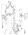
- an anesthesia delivery system 10 comprises a fresh gas supply 12, which provides fresh gas to breathing circuit 14.
- Breathing circuit 14 includes inspiratory conduit 36, expiratory conduit 38 and re-breathing conduit 39.
- Expiratory conduit 38 is in pneumatic communication with the interior of bellows 16, which is provided with a pop-off valve 20 and pop-off flow conduit 18.
- Pop-off flow sensor 21 generates a signal corresponding to the pop-off flow in conduit 18.
- Processor 22 communicates electronically with fresh gas supply 12, pop-off flow sensor, and breathing circuit 14 via sensors 24, as will be described below.
- Fresh gas supply 12 includes sources for oxygen, nitrous oxide, air, or other gases as is conventionally known. These sources provide gas to the gas flow controller 26, which includes computer controlled valves to meter the component gases according to signals on data bus 28 to processor 22. Mixed gas flow is conveyed to agent to signals on data bus 28 to processor 22. Mixed gas flow is conveyed to agent vaporizer 30, which provides anesthetic vapor to the mixed gas according to signals on data bus 32. The mixed gas/anesthetic vapor mixture is then conveyed to breathing circuit 14.
- Breathing circuit 14 functions to deliver inspiratory gas to the patient 100 and deliver expiratory gases from the patient.
- Fresh gas enters breathing circuit 14 via inlet conduit 34 and is then conveyed to the patient 100 via inspiratory limb 36.
- re-breathed gas is mixed with the fresh gas prior to its being inspired by patient 100.
- Expiratory limb 38 conveys expiratory gases away from the patient.
- a wye-piece is provided at the junction of the inspiratory limb and the expiratory limb for connection to the patient in a known manner.
- Carbon dioxide absorber 40 communicates with inspiratory conduit 36 and expiratory conduit 38 via re-breathing conduit 39 and functions to absorb carbon dioxide from the gases in the breathing circuit.
- flow in inspiratory conduit 36 is in the direction of arrow I and there is no flow in expiratory conduit 38.
- Rebreathed gases after passing through absorber 40, are mixed with fresh gas in conduit 34 and conveyed to inspiratory conduit 36.
- flow in expiratory conduit 38 is in the direction of arrow E and there is no flow in inspiratory conduit 36.
- Inspiratory check valve 42 and expiratory check valve 44 ensure unidirectional flow in the inspiratory limb 36 and expiratory limb 38, respectively.
- Bellows 16 as well as the volumes inside bellows conduit 46 and pop-off flow conduit 18, provide a reservoir for breathing gases.
- the exterior of bellows 16 may be subject to driving gases which are regulated by a drive gas ventilator in a known manner.
- a manually operated bag (not shown) may be used.
- Pop-off valve 20 includes a relief-type valve which communicates pneumatically with the interior space of bellows 16 and with the exterior space 17 of bellows 16.
- the relief valve is set to release gas from the breathing circuit 14 when a predetermined pressure differential exists across the valve, that is, when the pressure of gas in the bellows interior, and thus in the breathing circuit, exceed the pressure of gas in exterior space 17.
- a predetermined pressure differential exists across the valve, that is, when the pressure of gas in the bellows interior, and thus in the breathing circuit, exceed the pressure of gas in exterior space 17.
- a differential pressure will therefore develop across pop-off flow valve 20 and gas will be released from the breathing circuit 14.
- Pop-off flow sensor 21 which generates a signal corresponding to the flow of gas released from pop-off valve 20 and communicates that signal to processor 22.
- the breathing circuit is initially primed to fill its volume, and that of bellows 16 and conduits 46 and 20, with fresh gas.
- Pop-off flow sensor 21 detects the full volume condition in the breathing circuit 14.
- Patient inspiration either mechanical or spontaneous, is characterized by compression of bellows 16 and inspired gas flow from the bellows through absorber 40 and inspiratory limb 36, in the direction of arrow I, into the patient breathing tract.
- expiratory check valve 44 prevents flow from bellows 16 into expiratory limb 38.
- Fresh gas is provided from supply 12 to breathing circuit 14 as dictated by the control system according to the present invention.
- the inspired gas will comprise a mixture of fresh gas and re-breathed gas, depending on the commands issued to the gas flow controller 28 and agent vaporizer 32 from processor 22 in a manner to be described below.
- Patient expiration is characterized by expansion of bellows 16 as expired gases flow from the patient breathing tract through expiratory limb 38 into bellows 16.
- inspiratory check valve 42 prevents the flow of gases from inspiratory limb 36 into conduit 34 and re-breathing conduit 39.
- fresh gas if continuously flowing flows into absorber 40 and conduit 39 to add to the expansion of bellows 16. Inspiration and expiration may occur mechanically, that is, where the driving force for patient breathing is provided by bellows 16, or spontaneously, where the driving force for patient breathing originates in the muscular forces within the patient's body.
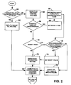
- Figure 2 is a flow chart depicting the logic flow of an algorithm for controlling a anesthesia delivery system according to the present invention.
- the algorithm may be implemented with a digital computer using any conventional programming language.
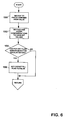
- the routine determines if the circuit fill mode of operation has been selected. If so, the circuit fill routine is executed as represented by block 52 and as explained below with reference to Fig. 6.
- Block 60 represents software routines for the oxygen and anesthetic agent controllers, respectively, which are proportional-integral controllers using feed forward as will be explained below with reference to Fig. 3.
- decision block 64 a determination is made as to whether the user-set values for oxygen or agent concentration have changed since the previous execution of the algorithm according to signals transmitted to processor 22 (Fig.
- a fresh gas boost routine is invoked as the program branches to 66, setting logical flag BOOST to a TRUE value.
- an integration is performed whereby the fresh gas flow (FGF) is integrated over the duration of the boost.
- FGF fresh gas flow
- This integrated boost flow corresponds to a high flow of fresh gas introduced into the breathing circuit from the supply 14 (Fig. 1).
- a determination is made as to whether the integrated boost flow exceeds a value corresponding to a constant volume dependent on the bellows and absorber volumes. If the integrated boost flow is less than or equal to the absorber volume multiplied by a constant, the fresh gas flow is boosted (or the boost continues if already invoked) at 72.
- the fresh gas flow is boosted to a value of 120% of the minute volume, which is the volume of gas delivered to or expired by the patient over during one minute.
- This boost flow has the effect of charging the breathing circuit with fresh gas at the new desired gas concentrations.
- the minute volume is typically measured by the ventilator flow monitoring devices.
- the routine then computes the flow and controller vaporizer commands, as will be described, at 80 and loops back to the beginning to re-execute.
- the FGF Minimization routine 76 will be bypassed during the fresh gas flow boost.
- the boost is terminated when the integrated boost flow exceeds the absorber volume multiplied by a constant, whereby the routine branches to 74, setting BOOST to a FALSE value.
- the FGF Minimization routine is then invoked at 76 and the flow controller and vaporizer commands computed at 80.
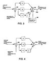
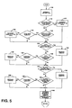
- Figs. 3 and 4 illustrate control diagrams for the oxygen and agent concentration control routines, respectively.
- These control systems utilize command signals from user interface 23 (Fig. 1) corresponding to desired values for the oxygen and agent concentrations.
- the actual values of the concentrations are detected via sensors 24 (Fig. 1) in the breathing circuit.
- Both control systems utilize proportional/integral controllers with command feedforward to minimize the difference between the user set value and the measured concentration in the breathing circuit.
- the measured O 2 concentration is subtracted from the user-set O 2 command at summation block 90.
- the resultant is fed forward through feed forward gain K f (preferably set to a value of 1.0).
- the Minute Volume and FGF values are obtained from the ventilator and computed from the delivery of the mixer and vaporizer, respectively, where FGF equals the previously commanded total fresh gas flow and MV equals the user-set minute volume of the ventilator, which is typically measured by the ventilator.
- Summation block 92 combines the resultant signals from the feedforward gain K f , proportional gain K p , and integral gain K i and O 2 consumption corrector 98 to yield an O 2 concentration control command 102.
- Integrator 94 is off when large changes are commanded by the user and on when the difference between the user set O 2 concentration and the measured O 2 concentration is small.
- Oxygen consumption corrector 98 functions to compensate for differences in the concentration of oxygen in the rebreathed and inspired gas.
- gases may be combined with fresh gas in the inspiratory limb.
- the rebreathed gas may contain less oxygen than the gas in the inspiratory limb because of oxygen consumed by the patient. Under such conditions, the oxygen concentration in the inspiratory limb will decrease as the rebreathed gas is combined with the gas in the inspiratory limb.
- the value of the output to summation block 92 is limited between 0.0 and (100% - the maximum deliverable oxygen concentration).
- the agent concentration control system incorporates a proportional-integral controller utilizing feed forward.
- the measured agent concentration signal is subtracted from the user-set agent concentration signal at summation block 96.
- Gain Kf is equal to 1.0.
- the gains are summed at block 104 to yield the agent concentration control command.
- the integrator 106 is off when large changes are commanded by the user and on when the difference between the user set agent concentration and the measured agent concentration is small.
- the fresh gas flow minimization routine determines the minimum amount of fresh gas flow required to maintain the breathing circuit volume, the user set oxygen and agent concentrations in the breathing circuit, and the user-set minimum fresh gas flow if the anesthesia delivery system is operating in a minimum fresh gas flow mode.
- Pop-off flow sensor 21, processor 22, sensors 24, gas flow controller 26 and agent vaporizer comprise a means for minimizing the pop-off flow, as will be described. Referring to Figure 5, at block 110, the pop-off flow is measured and a determination is made as to whether flow is too small.
- the minimum allowable flow value is about 100 ml/min.
- the variable PopMinFGF which corresponds to the minimum amount of fresh gas flow required to sustain permissible pop-off flow, is incremented at 112 by a constant value, preferably 150 ml/min.
- a determination is made as to whether the pop-off flow is above a predetermined maximum value.
- the maximum allowable flow value is about 200 ml/min. If the pop-off flow is above the maximum, the routine branches to decision block 116, to determine if the fresh gas flow rate is near the value for PopMinFGF. If so, the value for PopMinFGF is decreased by a predetermined constant value, preferably 150 ml/min at block 118 before the routine continues.
- the criterion at block 116 is necessary to prevent a zero pop-off flow condition that might otherwise develop in the case where significant flow is being exhausted from the pop-off valve, but the actual fresh gas flow is not at the value corresponding to PopMinFGF.
- the value for FGF is tested to be within 100ml/min of the value for PopMinFGF to ensure that the minimum being evaluated is the correct "floor" at which the minimum FGF should be set.
- the routine continues to block 120, which marks the beginning of the determination for the O 2 MinFGF, which is the minimum fresh gas flow required to accomplish the Oxygen Concentration Command generated by the control system described above with reference to Fig. 3.
- the routine determines if the oxygen concentration controllability margin is too small. That is, whether the current value for O 2 MinFGF provides an adequate margin for the oxygen concentration control system to respond to disturbances that might occur within one cycle of the routine. If the margin is determined to be too small, the value of O 2 MinFGF is gradually increased by an incremental amount in order to improve the controllability margin.
- DCC desired concentration control command
- OCC represents the current O 2 Concentration Control Command.
- the second condition corresponds to the zero-margin control state. If neither of the above conditions are satisfied, the block 122 is bypassed.
- Block 124 determines if the controllability margin provided by the current fresh gas flow rate is too large.
- the desired concentration command is computed as in formula (5) above.
- the value of O 2 MinFGF is decreased only if two conditions are satisfied: OCC ⁇ (DCC - 10%) and the value for O 2 MinFGF is near the current fresh gas flow, i.e., within 100 ml/min, as represented by block 126.
- the latter condition is necessary to prevent the value of O 2 MinFGF from being decremented when O 2 MinFGF is not the "floor" that needs to be adjusted.
- O 2 MinFGF O 2 MinFGF - (DCC - OCC)*FGF O 2 Incremental
- FGF O 2 Incremental is a constant, preferably 5 ml/min.
- Block 130 determines if the controllability margin provided by the current fresh gas flow rate is too small, i.e, whether the current value for AgtMinFGF provides an adequate margin for the anesthetic agent concentration control system to respond to disturbances that might occur within one cycle of the routine.
- the routine determines if the agent concentration controllability margin is too small. If the controllability margin is determined to be too small, the value of AgtMinFGF is incremented at block 132 in order to improve the controllability margin.
- DCC desired concentration control command
- ACC agent concentration command
- Block 134 determines if the controllability margin is too large and thus whether the value for AgtMinFGF may be further decreased.
- a desired concentration command is computed according to formula (6) above.
- the value of AgtMinFGF is decreased at 138 if both of the following conditions are satisfied: ACC ⁇ (DCC - 0.10*FSV) and the value for AgtMinFGF is approximately equal to the FGF, i.e., within 100 ml/min. as represented by block 136. If these two conditions are not satisfied, the routine continues without decreasing the value of AgtMinFGF.
- Block 140 corresponds to the computation of the fresh gas flow command based on the computed values of PopMinFGF, O 2 MinFGF, AgtMinFGF and a User-Set minimum for the fresh gas flow.
- the routine sets the minimum fresh gas flow command MinFGF to the maximum of these computed minimums.
- O 2 Gas flow command FGF * ((O 2 Concentration Control Command) - (100% - (Agent Concentration Control Command)) * 21%)/79%
- Balance Flow Controller FGF * (100% -(Agent Concentration Control Command))-(O 2 Gas Flow Controller Command)
- Agent Vaporizer Command Agent Concentration Control Command
- the circuit fill routine When the circuit fill is desired, the operator will set the circuit fill flag to TRUE via interface 23 (Fig. 1). The routine of Fig. 2 will then branch at 50 to the circuit fill routine.
- the circuit fill routine first sets the fresh gas flow to a predetermined high value (10 Umin.) at block 150. Contemporaneously, the gas and anesthetic vapor concentrations are set to the user-set valves at 152.
- a determination is made as to whether pop-off flow sensor 21 (Fig. 1) has detected exhausted gas. If so, the circuit fill flag is set to a FALSE value and when the circuit fill routine returns to the main routine represented in Fig. 2, the main routine will branch, at block 50, back to the O 2 and Agent control routines at 60.
- the routine of Fig. 6 returns without setting the circuit fill flag to FALSE.
- the circuit fill routine 52 (Fig. 2) is executed again and until the circuit fill flag is set to a FALSE value.
Landscapes
- Health & Medical Sciences (AREA)
- Anesthesiology (AREA)
- Emergency Medicine (AREA)
- Pulmonology (AREA)
- Engineering & Computer Science (AREA)
- Biomedical Technology (AREA)
- Heart & Thoracic Surgery (AREA)
- Hematology (AREA)
- Life Sciences & Earth Sciences (AREA)
- Animal Behavior & Ethology (AREA)
- General Health & Medical Sciences (AREA)
- Public Health (AREA)
- Veterinary Medicine (AREA)
- Respiratory Apparatuses And Protective Means (AREA)
- Medicines Containing Material From Animals Or Micro-Organisms (AREA)
- Pharmaceuticals Containing Other Organic And Inorganic Compounds (AREA)
Abstract
Description
If FGF >= 0.30 *Minute Volume then


O2 Gas Flow Controller Command = (O2 Concentration Control Command) * FGF
O2 Gas Flow Controller Command = FGF * ((O2 Concentration Control Command) - (100% - (Agent Concentration Control Command)) * 21%)/79%
Balance Gas Flow Controller =FGF * (100% -(Agent Concentration Control Command))-(O2 Gas Flow Controller Command)
Agent Vaporizer Command = Agent Concentration Control Command
Claims (10)
- A medical anesthesia delivery system 10 for administering respiration and anesthesia to a patient comprising:a) a gas supply 12 for providing fresh breathing gas comprised of a plurality of component gases;b) an anesthetic agent supply 30 for providing anesthetic agent to said fresh breathing gas;c) a breathing circuit 14 in communication with said gas supply 12 and said anesthetic agent supply 30 for delivering gas and anesthetic agent mixture to and away from said patient's respiratory tract, the breathing circuit including a pop-off valve 20 for releasing a pop-off flow of gas from the breathing circuit 14 in response to a predetermined pressure differential; andd) control means for controlling the concentration of at least one of said component gases and/or said anesthetic vapor in said breathing circuit and including means for minimizing said pop-off flow.
- An anesthesia delivery system as claimed in claim 1, wherein said means for minimizing said pop-off flow comprises means for determining a pop-off minimum fresh gas flow required to maintain a predetermined minimal pop-off flow.
- An anesthesia delivery system as claimed in claim 1 or 2, wherein one of said component gases is oxygen, said anesthesia delivery system further comprising:a) an oxygen sensor for generating a measured oxygen concentration signal representing the concentration of oxygen in said breathing circuit;b) an oxygen concentration controller for generating an oxygen concentration control command based upon said measured oxygen concentration signal;c) said means for minimizing said pop-off flow including means for determining an oxygen concentration minimum fresh gas flow based upon said oxygen concentration control command.
- An anesthesia delivery system as claimed in claim 1, 2 or 3 further comprising:a) an anesthetic agent sensor for generating a measured anesthetic agent concentration signal representing the concentration of anesthetic agent in said breathing circuit;b) an anesthetic agent concentration controller for generating an anesthetic agent concentration control command based upon said measured anesthetic agent concentration signal;c) said means for minimizing said pop-off flow including means for determining an agent minimum fresh gas flow based upon said anesthetic agent concentration control command.
- An anesthesia delivery system as claimed in claim 4, further comprising a user interface for permitting a user to input a user-set minimum fresh gas flow, said means for minimizing comprising means for adjusting said fresh gas flow to the maximum value of said pop-off, oxygen, agent and said user-set minimum fresh gas flows.
- An anesthesia delivery system as claimed in claim 4, wherein said anesthetic agent concentration controller generates an anesthetic concentration control command based upon the error between said measured anesthetic agent concentration signal and a user-set anesthetic agent concentration command.
- A method of controlling a medical anesthesia delivery system for administering respiration and anesthesia to a patient, the anesthesia delivery system including a gas supply for providing fresh breathing gas comprised of a plurality of component gases, an anesthetic agent supply for providing anesthetic agent to said fresh breathing gas, and a breathing circuit in communication with said gas supply for delivering gas and anesthetic agent mixture to and away from said patient's respiratory tract, the breathing circuit including pop-off valve for releasing a pop-off flow of gas from the breathing circuit in response to a predetermined pressure differential, the method comprising the step of:minimizing said pop-off flow while controlling the concentration of at least one of said component gases and said anesthetic agent in said breathing circuit.
- A method as claimed in claim 7, wherein said step of minimizing further comprises the step of:a) determining a pop-off minimum fresh gas flow required to maintain a predetermined pop-off flow.
- A medical anesthesia delivery system for administering respiration and anesthesia to a patient comprising:a) a gas supply for providing fresh breathing gas comprised of a plurality of component gases;b) an anesthetic agent supply for providing anesthetic agent to said fresh breathing gas;c) a breathing circuit in communication with said gas supply and said anesthetic agent supply for delivering gas and anesthetic agent mixture to and away from said patient's respiratory tract, the breathing circuit including a pop-off valve for releasing a pop-off flow of gas from the breathing circuit in response to a predetermined pressure differential;d) means for filling the breathing circuit with said fresh breathing gas and including means for terminating the filling when the pop-off flow occurs.
- A medical anesthesia delivery system for administering respiration and anesthesia to a patient comprising:a) a gas supply for providing fresh breathing gas comprising a plurality of component gases;b) an anesthetic agent supply for providing anesthetic agent to said fresh breathing gas;c) a breathing circuit in communication with said gas supply and said anesthetic agent supply for delivering gas and agent mixture to and away from said patient's respiratory tract;d) user input means for permitting an operator to input desired concentrations for said component gases and said anesthetic agent in said breathing circuit and for permitting said operator to input a desired user-set minimum total fresh gas flow;e) control means for controlling the concentration of at least one of said component gases in said breathing circuit and including: (i) means for boosting said fresh gas flow by a predetermined volume in response to a change in at least one of said desired concentrations; and (ii) means for maintaining the total fresh gas flow above said user-set minimum.
Applications Claiming Priority (2)
| Application Number | Priority Date | Filing Date | Title |
|---|---|---|---|
| US730508 | 1996-10-11 | ||
| US08/730,508 US5806513A (en) | 1996-10-11 | 1996-10-11 | Method and apparatus for controlling a medical anesthesia delivery system |
Publications (3)
| Publication Number | Publication Date |
|---|---|
| EP0835672A2 true EP0835672A2 (en) | 1998-04-15 |
| EP0835672A3 EP0835672A3 (en) | 1998-11-11 |
| EP0835672B1 EP0835672B1 (en) | 2004-07-14 |
Family
ID=24935655
Family Applications (1)
| Application Number | Title | Priority Date | Filing Date |
|---|---|---|---|
| EP97307647A Expired - Lifetime EP0835672B1 (en) | 1996-10-11 | 1997-09-29 | Anaesthesia delivery system |
Country Status (3)
| Country | Link |
|---|---|
| US (1) | US5806513A (en) |
| EP (1) | EP0835672B1 (en) |
| DE (1) | DE69729835T2 (en) |
Cited By (18)
| Publication number | Priority date | Publication date | Assignee | Title |
|---|---|---|---|---|
| WO1999052580A1 (en) * | 1998-04-14 | 1999-10-21 | Jaime Mas Marfany | Automatic control method for supplying anaesthetic to a low flow-type closed circuit |
| WO1999062581A3 (en) * | 1998-06-01 | 2000-03-09 | Axon Medical Inc | Closed rebreathing system |
| FR2803758A1 (en) | 2000-01-19 | 2001-07-20 | Taema | ANESTHESIA VENTILATOR WITH AUTOMATIC CIRCUIT SWITCHING |
| FR2806919A1 (en) * | 2000-04-04 | 2001-10-05 | Taema | Anesthetic respirator has CO2 gas accumulation ventilation balloon which in its automatic operating position is in mechanical ventilator and in its manual position is outside enclosure |
| US6892726B1 (en) | 1998-12-08 | 2005-05-17 | Instrumentarium Corp. | Arrangement in connection with equipment used in patient care |
| FR2883189A1 (en) * | 2005-03-17 | 2006-09-22 | Draeger Medical Ag | ANESTHETIC SYSTEM EQUIPPED WITH AN ANESTHETIC EVAPORATOR |
| CN1311877C (en) * | 1998-06-03 | 2007-04-25 | 斯科特实验室公司 | Devices and methods for relieving patients of suffering associated with medical or surgical procedures |
| US7290544B1 (en) | 1998-12-08 | 2007-11-06 | Ge Healthcare Finland Oy | Arrangement in connection with feedback control system |
| WO2010033439A3 (en) * | 2008-09-17 | 2010-06-17 | The Brigham And Women's Hospital, Inc. | Anesthesia simulator and controller for closed-loop anesthesia |
| EP2474334A1 (en) * | 2011-01-10 | 2012-07-11 | General Electric Company | System and method of preventing the delivery of hypoxic gases to a patient |
| EA016968B1 (en) * | 2009-09-29 | 2012-08-30 | Зао "Завод "Электромедоборудование" | System for delivering anesthetic with piezodoser and thermostatted evaporation chamber |
| CN102691850A (en) * | 2012-05-30 | 2012-09-26 | 张秀英 | Volume regulator for closed fluid circulation loop |
| EP2303375A4 (en) * | 2008-05-08 | 2014-03-05 | Edward Masionis | Portable life support apparatus ventilator |
| EP2682147A3 (en) * | 2012-07-06 | 2014-03-26 | General Electric Company | System and method of controlling the delivery of medical gases to a patient |
| US9233218B2 (en) | 2011-01-10 | 2016-01-12 | General Electric Comapny | System and method of controlling the delivery of medical gases to a patient |
| CN105727412A (en) * | 2016-05-04 | 2016-07-06 | 南京乐基医疗器械有限公司 | Anesthesia machine system and control method thereof |
| WO2016155083A1 (en) * | 2015-04-01 | 2016-10-06 | 深圳市科曼医疗设备有限公司 | Method, apparatus, and system for controlling ventilator oxygen concentration |
| CN110507886A (en) * | 2019-05-29 | 2019-11-29 | 赵晓明 | A kind of department of anesthesia's concentration adjusting anesthesia outfit |
Families Citing this family (45)
| Publication number | Priority date | Publication date | Assignee | Title |
|---|---|---|---|---|
| US6463930B2 (en) * | 1995-12-08 | 2002-10-15 | James W. Biondi | System for automatically weaning a patient from a ventilator, and method thereof |
| US6536430B1 (en) * | 1996-09-19 | 2003-03-25 | Charles A. Smith | Portable anesthesia rebreathing system |
| US5957129A (en) * | 1997-07-30 | 1999-09-28 | Ohmeda Inc. | On-line fault detection and correction in anesthesia delivery system |
| US5857458A (en) | 1997-09-26 | 1999-01-12 | Ohmeda Inc. | Automatic bellows refill |
| US6024087A (en) * | 1997-10-09 | 2000-02-15 | Ohmeda Inc. | Emergency oxygen flowmeter arrangement |
| US6216690B1 (en) * | 1997-10-15 | 2001-04-17 | Datex-Ohmeda, Inc. | Method and apparatus for rapid control of set inspired gas concentration in anesthesia delivery systems |
| DE19751597C2 (en) * | 1997-11-21 | 2000-02-03 | Draeger Medizintech Gmbh | Anesthesia ventilator |
| SE9801428D0 (en) * | 1998-04-23 | 1998-04-23 | Siemens Elema Ab | Anesthesia and a procedure at the anesthesia |
| US6575164B1 (en) * | 1998-10-15 | 2003-06-10 | Ntc Technology, Inc. | Reliability-enhanced apparatus operation for re-breathing and methods of effecting same |
| SE9803684D0 (en) * | 1998-10-27 | 1998-10-27 | Siemens Elema Ab | Anesthesia apparatus |
| SE9900368D0 (en) * | 1999-02-04 | 1999-02-04 | Siemens Elema Ab | Anesthesia apparatus |
| AUPQ466999A0 (en) * | 1999-12-15 | 2000-01-13 | Dunlop, Colin | Anaesthetic apparatus |
| DE20005004U1 (en) * | 2000-03-17 | 2000-06-08 | B. Braun Melsungen Ag, 34212 Melsungen | Anesthetic regulator |
| DE10041007C1 (en) * | 2000-08-22 | 2001-09-13 | Draeger Medizintech Gmbh | Method for controlling an artificial respiration equipment involves retraction of the respiration gas delivery unit at a rate determined by the volume rates of the exhaled air and the new gas supplied |
| SE0100064D0 (en) * | 2001-01-10 | 2001-01-10 | Siemens Elema Ab | Anaesthetic filter arrangement |
| CA2379353C (en) * | 2002-03-28 | 2012-07-31 | Joseph Fisher | A new method for continuous measurement of flux of gases in the lungs during breathing |
| SE0303064D0 (en) * | 2003-11-19 | 2003-11-19 | Maquet Critical Care Ab | Method and apparatus for reducing the carbon dioxide content in a dead volume |
| US7836882B1 (en) | 2005-01-07 | 2010-11-23 | Vetland Medical Sales And Services Llc | Electronic anesthesia delivery apparatus |
| US7438072B2 (en) * | 2005-03-02 | 2008-10-21 | Izuchukwu John I | Portable field anesthesia machine and control therefore |
| US7418964B2 (en) * | 2005-04-11 | 2008-09-02 | Ge Medical Systems Information Technologies | Anesthetic agent cassette with overlaid analog/digital signal interfaces |
| US20070168222A1 (en) * | 2006-01-19 | 2007-07-19 | Hoyme Kenneth P | System and method for providing hierarchical medical device control for automated patient management |
| RU2332242C2 (en) * | 2006-03-23 | 2008-08-27 | Василий Юрьевич Морозов | Method of anesthetic dosage and device for its implementation |
| DE102006027052B3 (en) * | 2006-06-10 | 2007-08-09 | Dräger Medical AG & Co. KG | Method for determination of consumption level of anesthetic substance, comprises use of data about all flows moving through respirator system |
| RU2332241C2 (en) * | 2006-08-29 | 2008-08-27 | Морозов Василий Юрьевич | Method of gas component feeding, device and apparatus for feeding inhalation narcosis |
| CA2662559C (en) | 2006-09-18 | 2014-12-02 | Alcon, Inc. | Surgical console |
| RU2329832C1 (en) * | 2006-09-28 | 2008-07-27 | Общество с ограниченной ответственностью "Научно-производственная фирма "МИНИВАП" | Method of stabilisation of anaesthetic target concentration and related device |
| DE102006051571B3 (en) * | 2006-11-02 | 2008-02-14 | Dräger Medical AG & Co. KG | Clinical respiration assembly determines the quantity of carbon dioxide that has been accumulated from a patient under full anaesthetic |
| RU2352362C2 (en) * | 2007-04-03 | 2009-04-20 | Василий Юрьевич Морозов | System of automatic control of oxygen supply at inhalation narcosis |
| DE102007019487B3 (en) * | 2007-04-25 | 2008-04-10 | Dräger Medical AG & Co. KG | Modular breathing system for patient, has stationary parts detachably attaching breathing module, and detachable connection interface for data, electrical energy and inhaled gas attached to stationary parts receiving module |
| WO2009062550A1 (en) * | 2007-11-14 | 2009-05-22 | Maquet Critical Care Ab | Anesthetic breathing apparatus having improved monitoring of anesthetic agent |
| EP2168623B1 (en) * | 2008-09-26 | 2011-09-21 | General Electric Company | Arrangement for detecting a leak in anesthesia system |
| US8267081B2 (en) | 2009-02-20 | 2012-09-18 | Baxter International Inc. | Inhaled anesthetic agent therapy and delivery system |
| US20110315139A1 (en) * | 2010-06-23 | 2011-12-29 | General Electric Company | Automatic fresh gas control system |
| JP6104513B2 (en) * | 2012-03-09 | 2017-03-29 | エア・ウォーター株式会社 | Ventilator |
| US8997784B2 (en) * | 2012-11-14 | 2015-04-07 | Shenzhen Mindray Bio-Medical Electronics Co. Ltd. | Electronic fluid flow controls with integrated manual fluid flow controls |
| US9539406B2 (en) * | 2013-09-10 | 2017-01-10 | General Electric Company | Interface device and method for supplying gas flow for subject breathing and apparatus for supplying anesthetic agent to the interface device |
| CN103785088A (en) * | 2013-09-29 | 2014-05-14 | 哈尔滨光凯科技开发有限公司 | Drug steam therapeutic instrument for respiratory system diseases |
| US20150290418A1 (en) * | 2013-10-11 | 2015-10-15 | Beth Israel Deaconess Medical Center, Inc. | Treatment of respiratory condition using targeted delivery |
| WO2017049247A1 (en) * | 2015-09-16 | 2017-03-23 | 12th Man Technologies, Inc. | Non-gas analyzer monitor of inspired gas concentration |
| CN105457139B (en) * | 2015-12-31 | 2017-12-05 | 深圳市诺然美泰科技股份有限公司 | Highly integrated source of the gas input processing and volume control device |
| WO2019075747A1 (en) * | 2017-10-20 | 2019-04-25 | 深圳迈瑞生物医疗电子股份有限公司 | Anesthesia machine, oxygen battery calibration system and calibration method thereof |
| DE102019002273A1 (en) * | 2019-03-29 | 2020-10-01 | Drägerwerk AG & Co. KGaA | Control system and method for controlling a fresh gas dosage for an anesthesia machine |
| JP7769938B2 (en) * | 2020-02-27 | 2025-11-14 | フィッシャー アンド ペイケル ヘルスケア リミテッド | Improvements related to gas flow supply |
| CN114748753A (en) * | 2022-03-30 | 2022-07-15 | 深圳市安保医疗科技股份有限公司 | Gas path system, anesthesia machine and gas path ventilation method |
| CN121311268A (en) * | 2023-06-16 | 2026-01-09 | 深圳迈瑞生物医疗电子股份有限公司 | Anesthesia machine |
Citations (1)
| Publication number | Priority date | Publication date | Assignee | Title |
|---|---|---|---|---|
| US5094235A (en) | 1989-05-10 | 1992-03-10 | Dragerwerk Aktiengesellschaft | Anesthesia ventilating apparatus having a breathing circuit and control loops for anesthetic gas components |
Family Cites Families (13)
| Publication number | Priority date | Publication date | Assignee | Title |
|---|---|---|---|---|
| US4051847A (en) * | 1972-01-17 | 1977-10-04 | Melvyn Lane Henkin | Anesthesia rebreathing apparatus |
| US4127121A (en) * | 1976-09-17 | 1978-11-28 | University Of Utah | Oxygen and anesthesia delivery and monitoring device |
| US4215409A (en) * | 1978-03-13 | 1980-07-29 | Mckesson Company | Flow control system for anesthesia apparatus |
| JPS55166163A (en) * | 1979-06-13 | 1980-12-25 | Citizen Watch Co Ltd | Controller for anesthetic gas |
| US4406302A (en) * | 1981-05-26 | 1983-09-27 | Puritan-Bennett Corporation | Pop-off gas evacuator valve for anesthesia machine |
| US4702241A (en) * | 1985-10-11 | 1987-10-27 | University Of Florida | Self-contained jet pump breathing apparatus |
| SE500550C2 (en) * | 1990-06-18 | 1994-07-11 | Siemens Elema Ab | Methods and apparatus for reducing gas re-breathing from the harmful space |
| US5320093A (en) * | 1990-12-21 | 1994-06-14 | Brigham And Women's Hospital | Rapid anesthesia emergence system using closed-loop PCO2 control |
| SE9100016D0 (en) * | 1991-01-03 | 1991-01-03 | Olof Werner | PROCEDURE AND DEVICE TO REGULATE INHALED CONCENTRATION OF GAS IN AN ANESTHESIA |
| US5398675A (en) * | 1992-10-14 | 1995-03-21 | Henkin; Melvyn L. | Anesthesia rebreathing system |
| SE470417B (en) * | 1993-02-05 | 1994-02-21 | Siemens Elema Ab | Method for fresh gas supply for manual ventilation and a fan system for carrying out the method |
| SE9402537L (en) * | 1994-07-20 | 1996-01-21 | Siemens Elema Ab | Anesthesia System |
| US5546931A (en) * | 1995-10-19 | 1996-08-20 | Rusz; Tibor | Anesthetic-vapor delivery apparatus with an ambient-referenced pressure regulator |
-
1996
- 1996-10-11 US US08/730,508 patent/US5806513A/en not_active Expired - Lifetime
-
1997
- 1997-09-29 EP EP97307647A patent/EP0835672B1/en not_active Expired - Lifetime
- 1997-09-29 DE DE69729835T patent/DE69729835T2/en not_active Expired - Fee Related
Patent Citations (1)
| Publication number | Priority date | Publication date | Assignee | Title |
|---|---|---|---|---|
| US5094235A (en) | 1989-05-10 | 1992-03-10 | Dragerwerk Aktiengesellschaft | Anesthesia ventilating apparatus having a breathing circuit and control loops for anesthetic gas components |
Cited By (22)
| Publication number | Priority date | Publication date | Assignee | Title |
|---|---|---|---|---|
| US6523537B1 (en) | 1998-04-14 | 2003-02-25 | Jaime Mas Marfany | Automatic control method for supplying anaesthetic to a low flow-type closed circuit |
| WO1999052580A1 (en) * | 1998-04-14 | 1999-10-21 | Jaime Mas Marfany | Automatic control method for supplying anaesthetic to a low flow-type closed circuit |
| WO1999062581A3 (en) * | 1998-06-01 | 2000-03-09 | Axon Medical Inc | Closed rebreathing system |
| CN1311877C (en) * | 1998-06-03 | 2007-04-25 | 斯科特实验室公司 | Devices and methods for relieving patients of suffering associated with medical or surgical procedures |
| US6892726B1 (en) | 1998-12-08 | 2005-05-17 | Instrumentarium Corp. | Arrangement in connection with equipment used in patient care |
| US7290544B1 (en) | 1998-12-08 | 2007-11-06 | Ge Healthcare Finland Oy | Arrangement in connection with feedback control system |
| FR2803758A1 (en) | 2000-01-19 | 2001-07-20 | Taema | ANESTHESIA VENTILATOR WITH AUTOMATIC CIRCUIT SWITCHING |
| EP1120126A2 (en) | 2000-01-19 | 2001-08-01 | Taema | Anaesthesia ventilator with automatic circuit switching |
| FR2806919A1 (en) * | 2000-04-04 | 2001-10-05 | Taema | Anesthetic respirator has CO2 gas accumulation ventilation balloon which in its automatic operating position is in mechanical ventilator and in its manual position is outside enclosure |
| FR2883189A1 (en) * | 2005-03-17 | 2006-09-22 | Draeger Medical Ag | ANESTHETIC SYSTEM EQUIPPED WITH AN ANESTHETIC EVAPORATOR |
| EP2303375A4 (en) * | 2008-05-08 | 2014-03-05 | Edward Masionis | Portable life support apparatus ventilator |
| WO2010033439A3 (en) * | 2008-09-17 | 2010-06-17 | The Brigham And Women's Hospital, Inc. | Anesthesia simulator and controller for closed-loop anesthesia |
| EA016968B1 (en) * | 2009-09-29 | 2012-08-30 | Зао "Завод "Электромедоборудование" | System for delivering anesthetic with piezodoser and thermostatted evaporation chamber |
| EP2474334A1 (en) * | 2011-01-10 | 2012-07-11 | General Electric Company | System and method of preventing the delivery of hypoxic gases to a patient |
| US8770192B2 (en) | 2011-01-10 | 2014-07-08 | General Electric Company | System and method of preventing the delivery of hypoxic gases to a patient |
| US9233218B2 (en) | 2011-01-10 | 2016-01-12 | General Electric Comapny | System and method of controlling the delivery of medical gases to a patient |
| US10398870B2 (en) | 2011-01-10 | 2019-09-03 | General Electric Company | System and method of controlling the delivery of medical gases to a patient |
| CN102691850A (en) * | 2012-05-30 | 2012-09-26 | 张秀英 | Volume regulator for closed fluid circulation loop |
| EP2682147A3 (en) * | 2012-07-06 | 2014-03-26 | General Electric Company | System and method of controlling the delivery of medical gases to a patient |
| WO2016155083A1 (en) * | 2015-04-01 | 2016-10-06 | 深圳市科曼医疗设备有限公司 | Method, apparatus, and system for controlling ventilator oxygen concentration |
| CN105727412A (en) * | 2016-05-04 | 2016-07-06 | 南京乐基医疗器械有限公司 | Anesthesia machine system and control method thereof |
| CN110507886A (en) * | 2019-05-29 | 2019-11-29 | 赵晓明 | A kind of department of anesthesia's concentration adjusting anesthesia outfit |
Also Published As
| Publication number | Publication date |
|---|---|
| DE69729835T2 (en) | 2005-08-25 |
| DE69729835D1 (en) | 2004-08-19 |
| US5806513A (en) | 1998-09-15 |
| EP0835672B1 (en) | 2004-07-14 |
| EP0835672A3 (en) | 1998-11-11 |
Similar Documents
| Publication | Publication Date | Title |
|---|---|---|
| EP0835672B1 (en) | Anaesthesia delivery system | |
| US6216690B1 (en) | Method and apparatus for rapid control of set inspired gas concentration in anesthesia delivery systems | |
| US8794234B2 (en) | Inversion-based feed-forward compensation of inspiratory trigger dynamics in medical ventilators | |
| EP0894506B1 (en) | On-line detection and correction in anesthesia delivery system | |
| CN102369036B (en) | PEEP regulation of breathing equipment | |
| CA2199100C (en) | Adaptive control system for a medical ventilator | |
| EP0425092B1 (en) | Apparatus for delivering gas to a patient | |
| JP3183527B2 (en) | Flow starter for assisted ventilation | |
| US5813399A (en) | System and method for closed loop airway pressure control during the inspiratory cycle of a breath in a patient ventilator using the exhalation valve as a microcomputer-controlled relief valve | |
| EP0560490B1 (en) | System for controlling a periodically actuated ventilation flow system | |
| WO2012051439A1 (en) | Systems and methods for controlling an amount of oxygen in blood of a ventilator patient | |
| JPH0838605A (en) | Anesthesia device | |
| JP2000070370A (en) | Artificial respiratory apparatus | |
| EP2588177B1 (en) | System for patient-synchronized ventilatory assist with endotracheal through-flow | |
| JPH1052494A (en) | Ventilator | |
| JPH11514909A (en) | Oxygen mixing in ventilation systems based on blowers | |
| JPS61128980A (en) | Artificial breathing method and apparatus for aiding inhalation of patient | |
| US20030168066A1 (en) | Mechanical breathing aid with adaptive expiration control | |
| US5727545A (en) | Gas mixing system for an anaesthetic apparatus | |
| EP0615764B1 (en) | System and method for closed loop inspiratory pressure control in a ventilator | |
| Behbehani | PLM Implementation of a Multiple Closed-Loop Control Strategy for a Microprocessor-Controlled Respirator | |
| CN116700367A (en) | Device and method for regulating gas flow | |
| CN121338187A (en) | Anesthesia machine and control method thereof |
Legal Events
| Date | Code | Title | Description |
|---|---|---|---|
| PUAI | Public reference made under article 153(3) epc to a published international application that has entered the european phase |
Free format text: ORIGINAL CODE: 0009012 |
|
| AK | Designated contracting states |
Kind code of ref document: A2 Designated state(s): DE ES FR GB IT |
|
| PUAL | Search report despatched |
Free format text: ORIGINAL CODE: 0009013 |
|
| AK | Designated contracting states |
Kind code of ref document: A3 Designated state(s): AT BE CH DE DK ES FI FR GB GR IE IT LI LU MC NL PT SE |
|
| 17P | Request for examination filed |
Effective date: 19990511 |
|
| AKX | Designation fees paid |
Free format text: DE ES FR GB IT |
|
| RAP1 | Party data changed (applicant data changed or rights of an application transferred) |
Owner name: DATEX-OHMEDA, INC. |
|
| 17Q | First examination report despatched |
Effective date: 20020625 |
|
| GRAJ | Information related to disapproval of communication of intention to grant by the applicant or resumption of examination proceedings by the epo deleted |
Free format text: ORIGINAL CODE: EPIDOSDIGR1 |
|
| GRAP | Despatch of communication of intention to grant a patent |
Free format text: ORIGINAL CODE: EPIDOSNIGR1 |
|
| GRAS | Grant fee paid |
Free format text: ORIGINAL CODE: EPIDOSNIGR3 |
|
| GRAA | (expected) grant |
Free format text: ORIGINAL CODE: 0009210 |
|
| AK | Designated contracting states |
Kind code of ref document: B1 Designated state(s): DE ES FR GB IT |
|
| PG25 | Lapsed in a contracting state [announced via postgrant information from national office to epo] |
Ref country code: IT Free format text: LAPSE BECAUSE OF FAILURE TO SUBMIT A TRANSLATION OF THE DESCRIPTION OR TO PAY THE FEE WITHIN THE PRESCRIBED TIME-LIMIT;WARNING: LAPSES OF ITALIAN PATENTS WITH EFFECTIVE DATE BEFORE 2007 MAY HAVE OCCURRED AT ANY TIME BEFORE 2007. THE CORRECT EFFECTIVE DATE MAY BE DIFFERENT FROM THE ONE RECORDED. Effective date: 20040714 Ref country code: FR Free format text: LAPSE BECAUSE OF FAILURE TO SUBMIT A TRANSLATION OF THE DESCRIPTION OR TO PAY THE FEE WITHIN THE PRESCRIBED TIME-LIMIT Effective date: 20040714 |
|
| REG | Reference to a national code |
Ref country code: GB Ref legal event code: FG4D |
|
| REF | Corresponds to: |
Ref document number: 69729835 Country of ref document: DE Date of ref document: 20040819 Kind code of ref document: P |
|
| PG25 | Lapsed in a contracting state [announced via postgrant information from national office to epo] |
Ref country code: ES Free format text: LAPSE BECAUSE OF FAILURE TO SUBMIT A TRANSLATION OF THE DESCRIPTION OR TO PAY THE FEE WITHIN THE PRESCRIBED TIME-LIMIT Effective date: 20041025 |
|
| PLBE | No opposition filed within time limit |
Free format text: ORIGINAL CODE: 0009261 |
|
| STAA | Information on the status of an ep patent application or granted ep patent |
Free format text: STATUS: NO OPPOSITION FILED WITHIN TIME LIMIT |
|
| 26N | No opposition filed |
Effective date: 20050415 |
|
| EN | Fr: translation not filed | ||
| PGFP | Annual fee paid to national office [announced via postgrant information from national office to epo] |
Ref country code: DE Payment date: 20070928 Year of fee payment: 11 |
|
| PG25 | Lapsed in a contracting state [announced via postgrant information from national office to epo] |
Ref country code: DE Free format text: LAPSE BECAUSE OF NON-PAYMENT OF DUE FEES Effective date: 20090401 |
|
| PGFP | Annual fee paid to national office [announced via postgrant information from national office to epo] |
Ref country code: GB Payment date: 20130927 Year of fee payment: 17 |
|
| GBPC | Gb: european patent ceased through non-payment of renewal fee |
Effective date: 20140929 |
|
| PG25 | Lapsed in a contracting state [announced via postgrant information from national office to epo] |
Ref country code: GB Free format text: LAPSE BECAUSE OF NON-PAYMENT OF DUE FEES Effective date: 20140929 |