EP0425092B1 - Apparatus for delivering gas to a patient - Google Patents
Apparatus for delivering gas to a patient Download PDFInfo
- Publication number
- EP0425092B1 EP0425092B1 EP90310357A EP90310357A EP0425092B1 EP 0425092 B1 EP0425092 B1 EP 0425092B1 EP 90310357 A EP90310357 A EP 90310357A EP 90310357 A EP90310357 A EP 90310357A EP 0425092 B1 EP0425092 B1 EP 0425092B1
- Authority
- EP
- European Patent Office
- Prior art keywords
- signal
- patient
- flow rate
- pressure
- flow
- Prior art date
- Legal status (The legal status is an assumption and is not a legal conclusion. Google has not performed a legal analysis and makes no representation as to the accuracy of the status listed.)
- Expired - Lifetime
Links
Images

Classifications
-
- A—HUMAN NECESSITIES
- A61—MEDICAL OR VETERINARY SCIENCE; HYGIENE
- A61M—DEVICES FOR INTRODUCING MEDIA INTO, OR ONTO, THE BODY; DEVICES FOR TRANSDUCING BODY MEDIA OR FOR TAKING MEDIA FROM THE BODY; DEVICES FOR PRODUCING OR ENDING SLEEP OR STUPOR
- A61M16/00—Devices for influencing the respiratory system of patients by gas treatment, e.g. mouth-to-mouth respiration; Tracheal tubes
- A61M16/20—Valves specially adapted to medical respiratory devices
- A61M16/201—Controlled valves
- A61M16/202—Controlled valves electrically actuated
- A61M16/203—Proportional
- A61M16/204—Proportional used for inhalation control
-
- A—HUMAN NECESSITIES
- A61—MEDICAL OR VETERINARY SCIENCE; HYGIENE
- A61M—DEVICES FOR INTRODUCING MEDIA INTO, OR ONTO, THE BODY; DEVICES FOR TRANSDUCING BODY MEDIA OR FOR TAKING MEDIA FROM THE BODY; DEVICES FOR PRODUCING OR ENDING SLEEP OR STUPOR
- A61M16/00—Devices for influencing the respiratory system of patients by gas treatment, e.g. mouth-to-mouth respiration; Tracheal tubes
- A61M16/0057—Pumps therefor
- A61M16/0066—Blowers or centrifugal pumps
- A61M16/0069—Blowers or centrifugal pumps the speed thereof being controlled by respiratory parameters, e.g. by inhalation
-
- A—HUMAN NECESSITIES
- A61—MEDICAL OR VETERINARY SCIENCE; HYGIENE
- A61M—DEVICES FOR INTRODUCING MEDIA INTO, OR ONTO, THE BODY; DEVICES FOR TRANSDUCING BODY MEDIA OR FOR TAKING MEDIA FROM THE BODY; DEVICES FOR PRODUCING OR ENDING SLEEP OR STUPOR
- A61M16/00—Devices for influencing the respiratory system of patients by gas treatment, e.g. mouth-to-mouth respiration; Tracheal tubes
- A61M16/021—Devices for influencing the respiratory system of patients by gas treatment, e.g. mouth-to-mouth respiration; Tracheal tubes operated by electrical means
- A61M16/022—Control means therefor
- A61M16/024—Control means therefor including calculation means, e.g. using a processor
- A61M16/026—Control means therefor including calculation means, e.g. using a processor specially adapted for predicting, e.g. for determining an information representative of a flow limitation during a ventilation cycle by using a root square technique or a regression analysis
-
- A—HUMAN NECESSITIES
- A61—MEDICAL OR VETERINARY SCIENCE; HYGIENE
- A61M—DEVICES FOR INTRODUCING MEDIA INTO, OR ONTO, THE BODY; DEVICES FOR TRANSDUCING BODY MEDIA OR FOR TAKING MEDIA FROM THE BODY; DEVICES FOR PRODUCING OR ENDING SLEEP OR STUPOR
- A61M16/00—Devices for influencing the respiratory system of patients by gas treatment, e.g. mouth-to-mouth respiration; Tracheal tubes
- A61M16/0057—Pumps therefor
- A61M16/0066—Blowers or centrifugal pumps
-
- A—HUMAN NECESSITIES
- A61—MEDICAL OR VETERINARY SCIENCE; HYGIENE
- A61M—DEVICES FOR INTRODUCING MEDIA INTO, OR ONTO, THE BODY; DEVICES FOR TRANSDUCING BODY MEDIA OR FOR TAKING MEDIA FROM THE BODY; DEVICES FOR PRODUCING OR ENDING SLEEP OR STUPOR
- A61M16/00—Devices for influencing the respiratory system of patients by gas treatment, e.g. mouth-to-mouth respiration; Tracheal tubes
- A61M16/0003—Accessories therefor, e.g. sensors, vibrators, negative pressure
- A61M2016/0015—Accessories therefor, e.g. sensors, vibrators, negative pressure inhalation detectors
- A61M2016/0018—Accessories therefor, e.g. sensors, vibrators, negative pressure inhalation detectors electrical
- A61M2016/0021—Accessories therefor, e.g. sensors, vibrators, negative pressure inhalation detectors electrical with a proportional output signal, e.g. from a thermistor
-
- A—HUMAN NECESSITIES
- A61—MEDICAL OR VETERINARY SCIENCE; HYGIENE
- A61M—DEVICES FOR INTRODUCING MEDIA INTO, OR ONTO, THE BODY; DEVICES FOR TRANSDUCING BODY MEDIA OR FOR TAKING MEDIA FROM THE BODY; DEVICES FOR PRODUCING OR ENDING SLEEP OR STUPOR
- A61M16/00—Devices for influencing the respiratory system of patients by gas treatment, e.g. mouth-to-mouth respiration; Tracheal tubes
- A61M16/0003—Accessories therefor, e.g. sensors, vibrators, negative pressure
- A61M2016/003—Accessories therefor, e.g. sensors, vibrators, negative pressure with a flowmeter
- A61M2016/0033—Accessories therefor, e.g. sensors, vibrators, negative pressure with a flowmeter electrical
- A61M2016/0036—Accessories therefor, e.g. sensors, vibrators, negative pressure with a flowmeter electrical in the breathing tube and used in both inspiratory and expiratory phase
-
- A—HUMAN NECESSITIES
- A61—MEDICAL OR VETERINARY SCIENCE; HYGIENE
- A61M—DEVICES FOR INTRODUCING MEDIA INTO, OR ONTO, THE BODY; DEVICES FOR TRANSDUCING BODY MEDIA OR FOR TAKING MEDIA FROM THE BODY; DEVICES FOR PRODUCING OR ENDING SLEEP OR STUPOR
- A61M16/00—Devices for influencing the respiratory system of patients by gas treatment, e.g. mouth-to-mouth respiration; Tracheal tubes
- A61M16/0003—Accessories therefor, e.g. sensors, vibrators, negative pressure
- A61M2016/003—Accessories therefor, e.g. sensors, vibrators, negative pressure with a flowmeter
- A61M2016/0033—Accessories therefor, e.g. sensors, vibrators, negative pressure with a flowmeter electrical
- A61M2016/0039—Accessories therefor, e.g. sensors, vibrators, negative pressure with a flowmeter electrical in the inspiratory circuit
-
- A—HUMAN NECESSITIES
- A61—MEDICAL OR VETERINARY SCIENCE; HYGIENE
- A61M—DEVICES FOR INTRODUCING MEDIA INTO, OR ONTO, THE BODY; DEVICES FOR TRANSDUCING BODY MEDIA OR FOR TAKING MEDIA FROM THE BODY; DEVICES FOR PRODUCING OR ENDING SLEEP OR STUPOR
- A61M2205/00—General characteristics of the apparatus
- A61M2205/15—Detection of leaks
-
- A—HUMAN NECESSITIES
- A61—MEDICAL OR VETERINARY SCIENCE; HYGIENE
- A61M—DEVICES FOR INTRODUCING MEDIA INTO, OR ONTO, THE BODY; DEVICES FOR TRANSDUCING BODY MEDIA OR FOR TAKING MEDIA FROM THE BODY; DEVICES FOR PRODUCING OR ENDING SLEEP OR STUPOR
- A61M2205/00—General characteristics of the apparatus
- A61M2205/35—Communication
- A61M2205/3546—Range
- A61M2205/3561—Range local, e.g. within room or hospital
Definitions
- the sleep apnea syndrome afflicts an estimated 1% to 3% of the general population and is due to episodic upper airway obstruction during sleep. Those afflicted with sleep apnea experience sleep fragmentation and intermittent, complete or nearly complete cessation of ventilation during sleep with potentially severe degrees of oxyhemoglobin unsaturation. These features may be translated clinically into debilitating daytime sleepiness, cardiac disrhythmias, pulmonary-artery hypertension, congestive heart failure and cognitive disfunction. Other sequelae of sleep apnea include right ventricular dysfunction with cor pulmonale, carbon dioxide retention during wakefulness as well as during sleep, and continuous reduced arterial oxygen tension. Hypersomnolent sleep apnea patients may be at risk for excessive mortality from these factors as well as by an elevated risk for accidents while driving and/or operating potentially dangerous equipment.
- the mechanism includes either anatomic or functional abnormalities of the upper airway which result in increased air flow resistance. Such abnormalities may include narrowing of the upper airway due to suction forces evolved during inspiration, the effect of gravity pulling the tongue back to appose the pharyngeal wall, and/or insufficient muscle tone in the upper airway dilator muscles. It has also been hypothesized that a mechanism responsible for the known association between obesity and sleep apnea is excessive soft tissue in the anterior and lateral neck which applies sufficient pressure on internal structures to narrow the airway.
- the treatment of sleep apnea has included such surgical interventions as uvalopalatopharyngoplasty, gastric surgery for obesity, and maxillo-facial reconstruction.
- Another mode of surgical intervention used in the treatment of sleep apnea is tracheostomy.
- Pharmacologic therapy has in general been disapponting, especially in patients with more than mild sleep apnea.
- side effects from the pharmacologic agents that have been used are frequent.
- medical practitioners continue to seek non-intrusive modes of treatment for sleep apnea with high success rates and high patient compliance including, for example in cases relating to obesity, weight loss through a regimen of exercise and regulated diet.
- U.S. patent 4,773,411 discloses a method and apparatus for ventilatory treatment characterized as airway pressure release ventilation and which provides a substantially constant elevated airway pressure with periodic short term reductions of the elevated airway pressure to a pressure magnitude no less than ambient atmospheric pressure.
- Publications pertaining to the application of CPAP in treatment of sleep apnea include the following:
- CPAP has been found to be very effective and well accepted, it suffers from some of the same limitations, although to a lesser degree, as do the surgery options; specifically a significant proportion of sleep apnea patients do not tolerate CPAP well. Thus, development of other viable non-invasive therapies has been a continuing objective in the art.
- US-A-4,773,411 discloses a CPAP apparatus including a controller for controlling the pressure of the gas supplied to the patient during both inhalation and exhalation, it serves as a useful starting point for the definition of the present invention.
- the invention consists of apparatus for delivering gas to and from the airway of a patient including a controller for controlling the pressure of the said gas during both inhalation and exhalation; characterized by a first processor for providing an instantaneous flow rate signal proportional to the instantaneous flow rate of the said gas during inhalation and exhalation; a second processor for providing a reference signal representing system leakage derived from said signal, and a comparator for comparing the instantaneous flow rate and reference signals, and for providing a drive signal for the pressure controller.
- positive pressure is applied alternately at relatively higher and lower pressure levels within the airway of the patient so that the pressure-induced force applied to dilate the patient's airway is alternately a larger and a smaller magnitude dilating force.
- the higher and lower magnitude positive pressures are initiated by spontaneous patient respiration with the higher magnitude pressure being applied during inspiration and the lower magnitude pressure being applied during expiration.
- the invention further contemplates a novel and improved apparatus which is operable to provide sleep apnea treatment. More specifically, a flow generator and an adjustable pressure controller supply air flow at a predetermined, adjustable pressure to the airway of a patient through a flow transducer. The flow transducer generates an output signal which is then conditioned to provide a signal proportional to the instantaneous flow rate of air to the patient. The instantaneous flow rate signal is fed to a low pass filter which passes only a signal indicative of the average flow rate over time. The average flow rate signal typically would be expected to be a value representing a non zero positive flow as the system is likely to have at least minimal leakage from the patient circuit (e.g. small leaks about the perimeter of the respiration mask worn by the patient).
- a flow generator and an adjustable pressure controller supply air flow at a predetermined, adjustable pressure to the airway of a patient through a flow transducer.
- the flow transducer generates an output signal which is then conditioned to provide a signal proportional to
- the average flow signal is indicative of such leakage because the summation of all other components of flow over time must be essentially zero since inspiration flow must equal expiration flow volume over time, that is, over a period of time the volume of air breathed in equals the volume of the gases breathed out.
- Both the instantaneous flow signal and the average flow rate signal are fed to an inspiration/expiration decision module which is, in its simplest form, a comparator that continually compares the input signals and provides a corresponding drive signal to the pressure controller.
- an inspiration/expiration decision module which is, in its simplest form, a comparator that continually compares the input signals and provides a corresponding drive signal to the pressure controller.
- the instantaneous flow exceeds average flow, the patient is inhaling and the drive signal supplied to the pressure controller sets the pressure controller to deliver air, at a preselected elevated pressure, to the airway of the patient.
- the decision circuitry thus provides a drive signal to set the pressure controller to provide a relatively lower magnitude of pressure in the airway of the patient.
- the patient's airway thus is maintained open by alternating higher and lower magnitudes of pressure which are applied during spontaneous inhalation and exhalation, respectively.
- CPAP mandates equal pressures during both inhalation and exhalation.
- the elevated pressure during both phases of breathing may create difficulty in exhaling and the sensation of an inflated chest.
- both inspiratory and expiratory air flow resistances in the airway are elevated during sleep preceding the onset of apnea, the airway flow resistance may be less during expiration than during inspiration.
- the bi-level CPAP therapy of our invention as characterized above may be sufficient to maintain pharyngeal patency during expiration even though the pressure applied during expiration is not as high as that needed to maintain pharyngeal patency during inspiration.
- some patients may have increased upper airway resistance primarily during inspiration with resulting adverse physiologic consequences.
- our invention also contemplates applying elevated pressure only during inhalation thus eliminating the need for global (inhalation and exhalation) increases in airway pressure.
- the relatively lower pressure applied during expiration may in some cases approach or equal ambient pressure.
- the lower pressure applied in the airway during expiration enhances patient tolerance by alleviating some of the uncomfortable sensations normally associated with CPAP.
- the switch between higher and lower pressure magnitudes can be controlled by spontaneous patient respiration, and the patient thus is able to independently govern respiration rate and volume.
- the invention contemplates automatic compensation for system leakage whereby nasal mask fit and air flow system integrity are of less consequence than in the prior art.
- other important benefits of the invention include lower mean airway pressures for the patient and enhanced safety, comfort and tolerance.
- Apparatus 10 is operable for delivering breathing gas such as air alternately at relatively higher and lower pressures (i.e., equal to or above ambient atmospheric pressure) to a patient 12 for treatment of the condition known as sleep apnea.
- breathing gas such as air alternately at relatively higher and lower pressures (i.e., equal to or above ambient atmospheric pressure) to a patient 12 for treatment of the condition known as sleep apnea.
- Apparatus 10 comprises a gas flow generator 14 (e.g., a blower) which receives breathing gas from any suitable source, a pressurized bottle 16 or the ambient atmosphere, for example.
- the gas flow from flow generator 14 is passed via a delivery conduit 20 to a breathing appliance such as a mask 22 of any suitable known construction which is worn by patient 12.
- the mask 22 may preferably be a nasal mask or a full face mask 22 as shown.
- Other breathing appliances which may be used in lieu of a mask include nasal cannulae, an endotracheal tube, or any other suitable appliance for interfacing between a source of breathing gas and a patient.
- the mask 22 includes a suitable exhaust port means, schematically indicated at 24, for exhaust of breathing gases during expiration.
- Exhaust port 24 preferably is a continuously open port which imposes a suitable flow resistance upon exhaust gas flow to permit a pressure controller 26, located in line with conduit 20 between flow generator 14 and mask 22, to control the pressure of air flow within conduit 20 and thus within the airway of the patient 12.
- a pressure controller 26 located in line with conduit 20 between flow generator 14 and mask 22, to control the pressure of air flow within conduit 20 and thus within the airway of the patient 12.
- exhaust port 24 may be of sufficient cross-sectional flow area to sustain a continuous exhaust flow of approximately 15 liters per minute.
- the flow via exhaust port 24 is one component, and typically the major component of the overall system leakage, which is an important parameter of system operation.
- a non-rebreathing valve may be substituted for the continuously open port 24.
- the pressure controller 26 is operative to control the pressure of breathing gas within the conduit 20 and thus within the airway of the patient.
- Pressure controller 26 is located preferably, although not necessarily, downstream of flow generator 14 and may take the form of an adjustable valve which provides a flow path which is open to the ambient atmosphere via a restricted opening, the valve being adjustable to maintain a constant pressure drop across the opening for all flow rates and thus a constant pressure within conduit 20.
- a suitable flow transducer 28 which generates an output signal that is fed as indicated at 29 to a flow signal conditioning circuit or pocessor 30 for generation of a signal proportional to the instantaneous flow rate of breathing gas within conduit 20 to the patient.
- flow generator 14 is not necessarily a positive displacement device. It may be, for example, a blower which creates a pressure head within conduit 20 and provides air flow only to the extent required to maintain that pressure head in the presence of patient breathing cycles, the exhaust opening 24, and action of pressure controller 26 as above described. Accordingly, when the patient is exhaling, peak exhalation flow rates from the lungs may far exceed the flow capacity of exhaust port 24. As a result, exhalation gas back flows within conduit 20 through flow transducer 28 and toward pressure controller 26, and the instantaneous flow rate signal from transducer 28 thus will vary widely within a range from relatively large positive (i.e. toward the patient) flow to relatively large negative (i.e. from the patient) flow.
- the instantaneous flow rate signal from flow signal conditioning circuitry 30 is fed as indicated at 32 to a decision module 34, a known comparator circuit for example, and is additionally fed as indicated at 36 to a low pass filter 38.
- Low pass filter 38 has a cut-off frequency low enough to remove from the instantaneous flow rate input signal most variations in the signal which are due to normal breathing.
- Low pass filter 38 also has a long enough time constant to ensure that spurious signals, aberrant flow patterns and peak instantaneous flow rate values will not dramatically affect system average flow. That is, the time constant of low pass filter 38 is selected to be long enough that it responds slowly to the instantaneous flow rate signal input.
- the average flow signal output from the low pass filter 38 is fed as indicated at 40 to decision circuitry 34 where the instantaneous flow rate signal is continually compared to the system average flow signal.
- the output of the decision circuitry 34 is fed as a drive signal indicated at 42 to the pressure controller 26.
- the pressure magnitude of breathing gas within conduit 20 thus is coordinated with the spontaneous breathing effort of the patient 12, as follows.
- the instantaneous flow rate signal goes to a positive value above the positive average flow signal value. Detection of this increase in decision circuitry 34 is sensed as the start of patient inhalation.
- the output signal from decision circuitry 34 is fed to pressure controller 26 which, in response, provides higher pressure gas flow within conduit 20 and thus higher pressure within the airway of the patient 12.
- This is the higher magnitude pressure value of our bi-level CPAP system and is referred to hereinbelow as IPAP (inhalation positive airway pressure).
- IPAP inhalation positive airway pressure
- the decision circuitry 34 senses this condition as the start of exhalation and provides a drive signal to pressure controller 26 which, in response, provides gas flow within conduit 20 at a lower pressure which is the lower magnitude pressure value of the bi-level CPAP system, referred to hereinbelow as EPAP (exhalation positive airway pressure).
- EPAP exhalation positive airway pressure
- the range of EPAP pressures may include ambient atmospheric pressure.
- the system 10 has a built-in controlled leakage via exhaust port 24 thus assuring that the average flow signal will be at least a small positive flow.
- the flow sensed by the flow transducer will be the sum of exhaust flow via port 24 and all other system leakage downstream of transducer 28, and inhalation flow within the airway of the patient 12. Accordingly, during inhalation the instantaneous flow rate signal as conditioned by conditioning module 30, will reliably and consistently reflect inhalation flow exceeding the average flow rate signal.
- the flow within conduit 20 reverses as exhalation flow from the lungs of the patient far exceeds the flow capacity of exhaust port 24. Accordingly, exhalation air backflows within conduit 20 past transducer 28 and toward pressure controller 26. Since pressure controller 26 is operable to maintain set pressure, it will act in response to flow coming from both the patient and the flow generator to open an outlet port sufficiently to accommodate the additional flow volume and thereby maintain the specified set pressure as determined by action of decision circuitry 34.
- the pressure of the gas within conduit 20 exerts a pressure within the airway of the patient to maintain an open airway and thereby alleviate airway constriction.
- a switching setpoint offset in the positive direction from system average flow may be provided such that the system will not switch to the IPAP mode until the patient actually exerts a significant spontaneous inspiratory effort of a minimum predetermined magnitude. This will ensure that the initiation of inhalation is completely spontaneous and not forced by an artificial increase in airway pressure.
- a similar switching setpoint offset may be provided when in the IPAP mode to ensure the transition to the lower pressure EPAP mode will occur before the flow rate of air into the lungs of the patient reaches zero (i.e. the switch to EPAP occurs Slightly before the patient ceases inhalation.) This will ensure that the patient will encounter no undue initial resistance to spontaneous exhalation.
- a novel method of treating sleep apnea is proposed according to which the airway pressure of the patient is maintained at a higher positive pressure during inspiration and a relatively lower pressure during expiration, all without interference with the spontaneous breathing of the patient.
- the described apparatus is operable to provide such treatment for sleep apnea patients by providing a flow of breathing gas to the patient at positive pressure, and varying the pressure of the air flow to provide alternately high and low pressure within the airway of the patient coordinated with the patient's spontaneous inhalation and exhalation.
- the flow rate of breathing gas to the patient is detected and processed to continually provide a signal which is proportional to the instantaneous breathing gas flow rate in the system.
- the instantaneous flow rate signal is further processed to eliminate variations attributable to normal patient respiration and other causes thus generating a signal which is proportional to the average or steady state system gas flow.
- the average flow signal is continually compared with the instantaneous flow signal as a means to detect the state of the patient's spontaneous breathing versus average system flow. When instantaneous flow exceeds the average flow, the patient is inhaling, and in response the pressure of gas flowing to the patient is set at a selected positive pressure, to provide a corresponding positive pressure within the airway of the patient.
- the pressure of breathing gas to the patient is adjusted to a selected lower pressure to provide a corresponding lower pressure within the airway of the patient.
- the low pass filter 38 is replaced by an estimated leak computer which includes a low pass filter as well as other functional elements as shown in Fig. 3.
- the remainder of the system as shown in Fig. 2 is similar in most respects to the system shown in Fig. 1. Accordingly, like elements are identified by like numbers, and the description hereinabove of Fig. 1 embodiment also applies generally to Fig. 2.
- the estimated leak computer 50 By using the operative capability of the estimated leak computer 50, as described hereinbelow, it is possible to adjust the reference signal which is fed to decision circuitry 34 on a breath by breath basis rather than merely relying on long term average system flow. To distinguish this new reference signal from average system flow it will be referred to hereinbelow as the estimated leak flow rate signal or just the estimated leak signal.
- the average system flow rate reference signal changes very slowly due to the long time constant of the low pass filter 38.
- This operative feature was intentionally incorporated to avoid disturbance of the reference signal by aberrant instantaneous flow rate signal inputs such as erratic breathing patterns. While it was possible to minimize the impact of such aberrations on the average flow rate reference signal, the average flow signal did nevertheless change, although by small increments and only very slowly in response to disturbances. Due to the long time constant of the low pass filter, such changes in the reference signal even if transitory could last for a long time.
- the system would never trigger between the IPAP and EPAP modes because the decision circuitry would never see an instantaneous flow rate signal greater than the average flow rate signal, at least not until a sufficient number of normal breathing cycles after application of the mask to the patient to bring the reference signal down to a value more closely commensurate with the actual system leak in operation.
- the low pass filter this could take a rather long time, during which time the patient would be breathing spontaneously against a uniform positive pressure. This would be tantamount to conventional CPAP and not at all in keeping with the present invention.
- two further modes of operation are envisioned, one being spontaneous/timed operation in which the system automatically triggers to the IPAP mode for just long enough to initiate patient inspiration if the system does not sense inspiratory effort within a selected time after exhalation begins.
- a timer is provided which is reset at the beginning of each patient inspiration whether the inspiratory cycle was triggered spontaneously or by the timer itself. Thus, only the start of inspiration is initiated by the timer. The rest of the operating cycle in this mode is controlled by spontaneous patient breathing and the circuitry of the system to be described.
- a further mode of operation is based purely on timed operation of the system rather than on spontaneous patient breathing effort, but with the timed cycles coordinated to spontaneous patient breathing.
- the estimated leak computer 50 includes the low pass filter 38′ as well as other circuits which are operative to make corrections to the estimated leak flow rate signal based on on-going analysis of each patient breath.
- a further circuit is provided which is operative to adjust the estimated leak flow rate signal quickly after major changes in system flow such as when the blower has been running prior to the time when the mask is first put on the patient, or after a major leak the system has either started or has been shut off.
- the low pass filter 38′ also includes a data storage capability whose function will be described hereinbelow.
- the low pass filter 38′ operates substantially as described above with reference to Fig. 1 in that it provides a long term average of system flow which is commensurate with steady state system leakage including the flow capacity of the exhaust port 24. This long term average is operative in the Fig. 3 embodiment to adjust the estimated leak flow rate reference signal only when system flow conditions are changing very slowly.
- a differential amplifier 52 receives the instantaneous flow rate signal as indicated at 54, and the estimated leak signal output from low pass filter 38′ as indicated at 56.
- the output of differential amplifier 52 is the difference between instantaneous flow rate and estimated leak flow rate, or in other words estimated instantaneous patient flow rate. This will be clear upon considering that instantaneous flow is the sum of patient flow plus actual system leakage.
- the estimated patient flow signal output from differential amplifier 52 is provided as indicated at 58 to a flow integrator 60 which integrates estimated patient flow breath by breath beginning and ending with the trigger to IPAP. Accordingly, an additional input to the flow integrator 60 is the IPAP/EPAP state signal as indicated at 62.
- the IPAP/EPAP state signal is the same as the drive signal provided to pressure controller 26; that is, it is a signal indicative of the pressure state, as between IPAP and EPAP, of the system. The state signal thus may be used to mark the beginning and end of each breath for purposes of breath by breath integration by integrator 60.
- the integral calculated by integrator 60 will be zero and no adjustment of estimated leak flow rate will result.
- the integral value in the form of an output signal from integrator 60 is provided as indicated at 64 to a sample and hold module 66.
- an output signal may be provided to module 66, but the ultimate result will be no adjustment of the estimated leak flow rate signal.
- a non-zero integral value provided to module 66 is further provided to module 38′ as indicated at 68 with each patient breath by operative action of the IPAP/EPAP state signal upon module 66 as indicated at 70.
- the effect of a non-zero integral value provided to module 38′ is an adjustment of the estimated leak flow rate signal proportional to the integral value and in the direction which would reduce the integral value towards zero on the next breath if all other conditions remain the same.
- the integrator circuit will compensate for the change in leak flow rate by incremental adjustments to the estimated leak flow rate within about ten patient breaths.
- the integrator circuit 60 also will adjust the estimated leak flow rate signal in response to non-zero net volume in a patient breathing cycle. It is not unusual for a patient's breathing volume to be non-zero. For example, a patient may inhale slightly more on each breath than he exhales over several breathing cycles, and then follow with a deeper or fuller exhalation. In this case, the integrator circuit would adjust the estimated leak flow rate signal as if the actual system leak rate had changed; however, since the reference signal correction is only about one tenth as large as would be required to make the total correction in one breath, the reference signal will not change appreciably over just one or two breaths. Thus, the integrator circuit accommodates both changes in system leakage and normal variations in patient breathing patterns. The integrator circuit normally would be active, for example, during rapid patient breathing.
- An end exhalation module 74 is operative to calculate another data component for use in estimating the system leak flow rate as follows.
- the module 74 monitors the slope of the instantaneous flow rate wave form. When the slope value is near zero during exhalation (as indicated by the state signal input 76) the indication is that the flow rate is not changing. If the slope of the instantaneous flow rate signal wave form remains small after more than one second into the respiratory phase, the indication is that exhalation has ended and that the net flow rate at this point thus is the leak flow rate. However, if estimated patient flow rate is non-zero at the same time, one component of the instantaneous flow rate signal must be patient flow.
- the circuit adjusts the estimated leak flow rate slowly in a direction to move estimated patient flow rate toward zero to conform to instantaneous patient flow conditions expected at the end of exhalation.
- the adjustment to estimated leak flow rate is provided as an output from module 74 to low pass filter 38′ as indicated at 80.
- this control mechanism takes effect, it disables the breath by breath volume correction capability of integrator circuit 60 for that breath only.
- the output of module 74 is a time constant control signal which is provided to low pass filter 38′ to temporarily shorten the time constant thereof for a sufficient period to allow the estimated leak flow rate to approach the instantaneous flow rate signal at that specific instant. It will be noted that shortening the low pass filter time constant increases the rapidity with which the low pass filter output (a system average) can adjust toward the instantaneous flow rate signal input.
- a gross error detector 82 which acts when the estimated patient flow rate, provided thereto as indicated at 84, is away from zero for more than about 5 seconds. Such a condition may normally occur, for example, when the flow generator 14 is running before mask 22 is applied to the patient. This part of the control system is operative to stabilize operation quickly after major changes in the leak rate occur.
- low pass filter 38′ acts on the instantaneous flow rate signal to provide an output corresponding to average system flow, which is system leakage since patient inspiration and expiration over time constitutes a net positive flow of zero.
- the system average flow can be viewed as an estimate of leakage flow rate.
- the differential amplifier 52 processes the instantaneous flow rate signal and the estimated leak flow rate signal to provide an estimated patient flow rate signal which is integrated and non-zero values of the integral are fed back to module 38′ to adjust the estimated leak flow rate signal on a breath by breath basis.
- the integrator 60 is reset by the IPAP/EPAP state signal via connection 62.
- Two circuits are provided which can override the integrator circuit, including end exhalation detector 74 which provides an output to adjust the time constant of low pass filter 38′ and which also is provided as indicated at 86 to reset integrator 60.
- Gross error detector 82 is also provided to process estimated patient flow rate and to provide an adjustment to estimated leak flow rate under conditions as specified.
- the output of module 82 also is utilized as an integrator reset signal as indicated at 86. It will be noted that the integrator 60 is reset with each breath of the patient if, during that breath, it is ultimately overridden by module 74 or 82. Accordingly, the multiple reset capabilities for integrator 60 as described are required.
- the system may be utilized in a spontaneous triggering mode, a spontaneous/timed mode or a purely timed mode of operation.
- spontaneous operation decision circuitry 34 continuously compares the instantaneous flow rate with estimated leak flow rate. If the system is in the EPAP state or mode, it remains there until instantaneous flow rate exceeds estimated leak flow rate by approximately 40 cc per second. When this transition occurs, decision circuitry 34 triggers the system into the IPAP mode for 150 milliseconds. The system will then normally remain in the IPAP mode as the instantaneous flow rate to the patient will continue to increase during inhalation due to spontaneous patient effort and the assistance of the increased IPAP pressure.
- a temporary offset is added to the estimated leak flow rate reference signal.
- the offset is proportional to the integral of estimated patient flow rate beginning at initiation of the inspiratory breath so that it gradually increases with time during inspiration at a rate proportional to the patient's inspiratory flow rate. Accordingly, the flow rate level above estimated leak flow needed to keep the system in the IPAP mode during inhalation decreases with time from the beginning of inhalation and in proportion to the inspiratory flow rate. With this enhancement,the longer an inhalation cycle continues, the larger is the reference signal below which instantaneous flow would have to decrease in order to trigger the EPAP mode.
- a transition to EPAP will occur when his flow rate drops to about 167 cc per second after one second, or 333 cc per second after two seconds, or 500 cc per second after three seconds, and so forth.
- the triggers would occur at 83, 167 and 250 cc per second at one, two and three seconds into IPAP, respectively.
- the EPAP trigger threshold comes up to meet the inspiratory flow rate with the following benefits.
- the volume-based leak correction circuit i.e. integrator 60
- the trigger threshold Upon switching back to the EPAP mode, the trigger threshold will remain above the estimated leak flow rate for approximately 500 milliseconds to allow the system to remain stable in the EPAP mode without switching again while the respective flow rates are changing. After 500 milliseconds, the trigger threshold offset is reset to zero to await the next inspiratory effort.
- the normal state for the circuit is for it to remain in the EPAP mode until an inspiratory effort is made by the patient.
- the automatic corrections and adjustments to the reference signal are effective to keep the system from locking up in the IPAP mode and to prevent auto-triggering while at the same time providing a high level of sensitivity to inspiratory effort and rapid adjustment for changing leak conditions and breathing patterns.
- the system performs exactly as above described with reference to spontaneous operation, except that it allows selection of a minimum breathing rate to be superimposed upon the spontaneous operating mode. If the patient does not make an inspiratory effort within a predetermined time, the system will automatically trigger to the IPAP mode for 200 milliseconds. The increased airway pressure for this 200 milliseconds will initiate patent inspiration and provide sufficient time that spontaneous patient flow will exceed the reference signal so that the rest of the cycle may continue in the spontaneous mode as above described. The breaths per minute timer is reset by each trigger to IPAP whether the transition was triggered by the patient or by the timer itself.
- all triggering between IPAP and EPAP modes is controlled by a timer with a breath per minute control being used to select a desired breathing rate from, for example, 3 to 30 breaths per minute. If feasible, the selected breathing rate is coordinated to the patient's spontaneous breathing rate.
- the percent IPAP control is used to set the fraction of each breathing cycle to be spent in the IPAP mode. For example, if the breaths per minute control is set to 10 breaths per minute (6 seconds per breath) and the percent IPAP control is set to 33%, then the flow generator will spend, in each breathing cycle, two seconds in IPAP and four seconds in EPAP.
- Fig. 4 illustrates a control panel for controlling the system above described and including a function selector switch which includes function settings for the three operating modes of spontaneous, spontaneous/timed, and timed as above described.
- the controls for spontaneous mode operation include IPAP and EPAP pressure adjustment controls 90 and 92, respectively. These are used for setting the respective IPAP and EPAP pressure levels.
- controls 90 and 92 are utilized as before to set IPAP and EPAP pressure levels, and breaths per minute control 94 additionally is used to set the minimum desired breathing rate in breaths per minute.
- controls 90, 92 and 94 are effective, and in addition the per cent IPAP control 96 is used to set the time percentage of each breath to be spent in the IPAP mode.
- Lighted indicators such as LED's 97, 98 and 100 are also provided to indicate whether the system is in the IPAP or EPAP state, and to indicate whether in the spontaneous/timed mode of operation the instantaneous state of the system is spontaneous operation or timed operation.
Description
- The sleep apnea syndrome afflicts an estimated 1% to 3% of the general population and is due to episodic upper airway obstruction during sleep. Those afflicted with sleep apnea experience sleep fragmentation and intermittent, complete or nearly complete cessation of ventilation during sleep with potentially severe degrees of oxyhemoglobin unsaturation. These features may be translated clinically into debilitating daytime sleepiness, cardiac disrhythmias, pulmonary-artery hypertension, congestive heart failure and cognitive disfunction. Other sequelae of sleep apnea include right ventricular dysfunction with cor pulmonale, carbon dioxide retention during wakefulness as well as during sleep, and continuous reduced arterial oxygen tension. Hypersomnolent sleep apnea patients may be at risk for excessive mortality from these factors as well as by an elevated risk for accidents while driving and/or operating potentially dangerous equipment.
- Although details of the pathogenesis of upper airway obstruction in sleep apnea patients have not been fully defined, it is generally accepted that the mechanism includes either anatomic or functional abnormalities of the upper airway which result in increased air flow resistance. Such abnormalities may include narrowing of the upper airway due to suction forces evolved during inspiration, the effect of gravity pulling the tongue back to appose the pharyngeal wall, and/or insufficient muscle tone in the upper airway dilator muscles. It has also been hypothesized that a mechanism responsible for the known association between obesity and sleep apnea is excessive soft tissue in the anterior and lateral neck which applies sufficient pressure on internal structures to narrow the airway.
- The treatment of sleep apnea has included such surgical interventions as uvalopalatopharyngoplasty, gastric surgery for obesity, and maxillo-facial reconstruction. Another mode of surgical intervention used in the treatment of sleep apnea is tracheostomy. These treatments constitute major undertakings with considerable risk of post-operative morbidity if not mortality. Pharmacologic therapy has in general been disapponting, especially in patients with more than mild sleep apnea. In addition, side effects from the pharmacologic agents that have been used are frequent. Thus, medical practitioners continue to seek non-intrusive modes of treatment for sleep apnea with high success rates and high patient compliance including, for example in cases relating to obesity, weight loss through a regimen of exercise and regulated diet.
- Recent work in the treatment of sleep apnea has included the use of continuous positive airway pressure (CPAP) to maintain the airway of the patient in a continuously open state during sleep. For example, U.S. patent 4,655,213 and Australian patent AU-B-83901/82 both disclose sleep apnea treatments based on continuous positive airway pressure applied within the airway of the patient.
- Also of interest is U.S. patent 4,773,411 which discloses a method and apparatus for ventilatory treatment characterized as airway pressure release ventilation and which provides a substantially constant elevated airway pressure with periodic short term reductions of the elevated airway pressure to a pressure magnitude no less than ambient atmospheric pressure.
- Publications pertaining to the application of CPAP in treatment of sleep apnea include the following:
- 1. Lindsay, DA, Issa FG, and Sullivan C.E. "Mechanisms of Sleep Desaturation in Chronic Airflow Limitation Studied with Nasal Continuous Positive Airway Pressure (CPAP), "Am Rev Respir Dis, 1982; 125: p.112.
- 2. Sanders MH, Moore SE, Eveslage J. "CPAP via nasal mask: A treatment for occlusive sleep apnea," Chest, 1983; 83: pp. 144-145.
- 3. Sullivan CE, Berthon-Jones M, Issa FG. "Remission of severe obesity-hypoventilation syndrome after short-term treatment during sleep with continuous positive airway pressure," Am Rev Respir Dis, 1983; 128: pp. 177-181.
- 4. Sullivan CE, Issa FG, Berthon-Jones M, Eveslage. "Reversal of obstructive sleep apnea by contnuous positive airway pressure applied through the nares," Lancet, 1981; 1: pp. 862-865.
- 5. Sullivan CE, Berthon-Jones M. Issa FG. "Treatment of obstructive apnea with continuous positive airway pressure applied through the nose." Am Rev Respir Dis, 1982; 125: p.107. Annual Meeting Abstracts.
- 6. Rapoport DM, Sorkin B, Garay SM, Goldring RM. "Reversal of the 'Pickwickian Syndrome' by long-term use of nocturnal nasal-airway pressure," N Engl J. Med, 1982; 307: pp.931-933.
- 7. Sanders MH, Holzer BC, Pennock BE. "The effect of nasal CPAP on various sleep apnea patterns," Chest, 1983; 84: p.336. Presented at the Annual Meeting of the American College of Chest Physicians, Chicago IL, October 1983.
- Although CPAP has been found to be very effective and well accepted, it suffers from some of the same limitations, although to a lesser degree, as do the surgery options; specifically a significant proportion of sleep apnea patients do not tolerate CPAP well. Thus, development of other viable non-invasive therapies has been a continuing objective in the art.
- Reference is made to the published Patent Cooperation Treaty WO89/05669 and GB Application No. 2079984A which disclose inter alia a flow meter and allied apparatus which contribute to a repetitive determination of the patient's tidal volume during use, such data to be used in conditioning associated respiratory apparatus. Values of a patient's tidal volume are not necessary to the operation of the present invention.
- Insofar as US-A-4,773,411 discloses a CPAP apparatus including a controller for controlling the pressure of the gas supplied to the patient during both inhalation and exhalation, it serves as a useful starting point for the definition of the present invention.
- The invention consists of apparatus for delivering gas to and from the airway of a patient including a controller for controlling the pressure of the said gas during both inhalation and exhalation; characterized by a first processor for providing an instantaneous flow rate signal proportional to the instantaneous flow rate of the said gas during inhalation and exhalation; a second processor for providing a reference signal representing system leakage derived from said signal, and a comparator for comparing the instantaneous flow rate and reference signals, and for providing a drive signal for the pressure controller.
- In one embodiment of the invention, positive pressure is applied alternately at relatively higher and lower pressure levels within the airway of the patient so that the pressure-induced force applied to dilate the patient's airway is alternately a larger and a smaller magnitude dilating force. The higher and lower magnitude positive pressures are initiated by spontaneous patient respiration with the higher magnitude pressure being applied during inspiration and the lower magnitude pressure being applied during expiration.
- The invention further contemplates a novel and improved apparatus which is operable to provide sleep apnea treatment. More specifically, a flow generator and an adjustable pressure controller supply air flow at a predetermined, adjustable pressure to the airway of a patient through a flow transducer. The flow transducer generates an output signal which is then conditioned to provide a signal proportional to the instantaneous flow rate of air to the patient. The instantaneous flow rate signal is fed to a low pass filter which passes only a signal indicative of the average flow rate over time. The average flow rate signal typically would be expected to be a value representing a non zero positive flow as the system is likely to have at least minimal leakage from the patient circuit (e.g. small leaks about the perimeter of the respiration mask worn by the patient). The average flow signal is indicative of such leakage because the summation of all other components of flow over time must be essentially zero since inspiration flow must equal expiration flow volume over time, that is, over a period of time the volume of air breathed in equals the volume of the gases breathed out.
- Both the instantaneous flow signal and the average flow rate signal are fed to an inspiration/expiration decision module which is, in its simplest form, a comparator that continually compares the input signals and provides a corresponding drive signal to the pressure controller. In general, when the instantaneous flow exceeds average flow, the patient is inhaling and the drive signal supplied to the pressure controller sets the pressure controller to deliver air, at a preselected elevated pressure, to the airway of the patient. Similarly, when the instantaneous flow rate is less than the average flow rate, the patient is exhaling and the decision circuitry thus provides a drive signal to set the pressure controller to provide a relatively lower magnitude of pressure in the airway of the patient. The patient's airway thus is maintained open by alternating higher and lower magnitudes of pressure which are applied during spontaneous inhalation and exhalation, respectively.
- As has been noted, some sleep apnea patients do not tolerate standard CPAP therapy. Specifically, approximately 25% of patients cannot tolerate CPAP due to the attendant discomfort. CPAP mandates equal pressures during both inhalation and exhalation. The elevated pressure during both phases of breathing may create difficulty in exhaling and the sensation of an inflated chest. However, we have determined that although both inspiratory and expiratory air flow resistances in the airway are elevated during sleep preceding the onset of apnea, the airway flow resistance may be less during expiration than during inspiration. Thus it follows that the bi-level CPAP therapy of our invention as characterized above may be sufficient to maintain pharyngeal patency during expiration even though the pressure applied during expiration is not as high as that needed to maintain pharyngeal patency during inspiration. In addition, some patients may have increased upper airway resistance primarily during inspiration with resulting adverse physiologic consequences. Thus, our invention also contemplates applying elevated pressure only during inhalation thus eliminating the need for global (inhalation and exhalation) increases in airway pressure. The relatively lower pressure applied during expiration may in some cases approach or equal ambient pressure. The lower pressure applied in the airway during expiration enhances patient tolerance by alleviating some of the uncomfortable sensations normally associated with CPAP.
- Under prior CPAP therapy, pressures as high as 15 cm H₂O have been required, and some patients on nasal CPAP thus have been needlessly exposed to unnecessarily high expiratory pressures with the attendant discomfort and elevated mean airway pressure, and theoretic risk of barotrauma. Our invention permits independent application of a higher inspiratory airway pressure in conjunction with a lower expiratory airway pressure in order to provide a therapy which is better tolerated by the 25% of the patient population which does not tolerate CPAP therapy, and which may be safer in the other 75% of the patient population.
- As has been noted hereinabove, the switch between higher and lower pressure magnitudes can be controlled by spontaneous patient respiration, and the patient thus is able to independently govern respiration rate and volume. As has been also noted, the invention contemplates automatic compensation for system leakage whereby nasal mask fit and air flow system integrity are of less consequence than in the prior art. In addition to the benefit of automatic leak compensation, other important benefits of the invention include lower mean airway pressures for the patient and enhanced safety, comfort and tolerance.
-
- Fig. 1 is a functional block diagram of an apparatus according to the invention;
- Fig. 2 is a functional block diagram showing an alternative embodiment of the invention;
- Fig. 3 is a functional block diagram of the Estimated Leak Computer of Fig. 2; and
- Fig. 4 is a frontal elevation of a control panel for the apparatus of this invention.
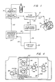
- There is generally indicated at 10 in Fig. 1 an apparatus according to one presently preferred embodiment of the instant invention and shown in the form of a functional block diagram.
Apparatus 10 is operable for delivering breathing gas such as air alternately at relatively higher and lower pressures (i.e., equal to or above ambient atmospheric pressure) to apatient 12 for treatment of the condition known as sleep apnea. -
Apparatus 10 comprises a gas flow generator 14 (e.g., a blower) which receives breathing gas from any suitable source, apressurized bottle 16 or the ambient atmosphere, for example. The gas flow fromflow generator 14 is passed via adelivery conduit 20 to a breathing appliance such as amask 22 of any suitable known construction which is worn bypatient 12. Themask 22 may preferably be a nasal mask or afull face mask 22 as shown. Other breathing appliances which may be used in lieu of a mask include nasal cannulae, an endotracheal tube, or any other suitable appliance for interfacing between a source of breathing gas and a patient. - The
mask 22 includes a suitable exhaust port means, schematically indicated at 24, for exhaust of breathing gases during expiration.Exhaust port 24 preferably is a continuously open port which imposes a suitable flow resistance upon exhaust gas flow to permit apressure controller 26, located in line withconduit 20 betweenflow generator 14 andmask 22, to control the pressure of air flow withinconduit 20 and thus within the airway of thepatient 12. For example,exhaust port 24 may be of sufficient cross-sectional flow area to sustain a continuous exhaust flow of approximately 15 liters per minute. The flow viaexhaust port 24 is one component, and typically the major component of the overall system leakage, which is an important parameter of system operation. In an alternative embodiment to be discussed hereinbelow, it has been found that a non-rebreathing valve may be substituted for the continuouslyopen port 24. - The
pressure controller 26 is operative to control the pressure of breathing gas within theconduit 20 and thus within the airway of the patient.Pressure controller 26 is located preferably, although not necessarily, downstream offlow generator 14 and may take the form of an adjustable valve which provides a flow path which is open to the ambient atmosphere via a restricted opening, the valve being adjustable to maintain a constant pressure drop across the opening for all flow rates and thus a constant pressure withinconduit 20. - Also interposed in line with
conduit 20, preferably downstream ofpressure controller 26, is asuitable flow transducer 28 which generates an output signal that is fed as indicated at 29 to a flow signal conditioning circuit orpocessor 30 for generation of a signal proportional to the instantaneous flow rate of breathing gas withinconduit 20 to the patient. - It will be appreciated that
flow generator 14 is not necessarily a positive displacement device. It may be, for example, a blower which creates a pressure head withinconduit 20 and provides air flow only to the extent required to maintain that pressure head in the presence of patient breathing cycles, theexhaust opening 24, and action ofpressure controller 26 as above described. Accordingly, when the patient is exhaling, peak exhalation flow rates from the lungs may far exceed the flow capacity ofexhaust port 24. As a result, exhalation gas back flows withinconduit 20 throughflow transducer 28 and towardpressure controller 26, and the instantaneous flow rate signal fromtransducer 28 thus will vary widely within a range from relatively large positive (i.e. toward the patient) flow to relatively large negative (i.e. from the patient) flow. - The instantaneous flow rate signal from flow
signal conditioning circuitry 30 is fed as indicated at 32 to adecision module 34, a known comparator circuit for example, and is additionally fed as indicated at 36 to alow pass filter 38.Low pass filter 38 has a cut-off frequency low enough to remove from the instantaneous flow rate input signal most variations in the signal which are due to normal breathing.Low pass filter 38 also has a long enough time constant to ensure that spurious signals, aberrant flow patterns and peak instantaneous flow rate values will not dramatically affect system average flow. That is, the time constant oflow pass filter 38 is selected to be long enough that it responds slowly to the instantaneous flow rate signal input. Accordingly, most instantaneous flow rate input signals which could have a large impact on system average flow in the short term have a much smaller impact over a longer term, largely because such instantaneous flow rate signal components will tend to cancel over the longer term. For example, peak instantaneous flow rate values will tend to be alternating relatively large positive and negative flow values corresponding to peak inhalation and exhalation flow achieved by the patient during normal spontaneous breathing. The output oflow pass filter 38 thus is a signal which is proportional to the average flow in the system, and this is typically a positive flow which corresponds to average system leakage (including flow from exhaust 24) since, as noted, inhalation and exhalation flow cancel for all practical purposes. - The average flow signal output from the
low pass filter 38 is fed as indicated at 40 todecision circuitry 34 where the instantaneous flow rate signal is continually compared to the system average flow signal. The output of thedecision circuitry 34 is fed as a drive signal indicated at 42 to thepressure controller 26. The pressure magnitude of breathing gas withinconduit 20 thus is coordinated with the spontaneous breathing effort of thepatient 12, as follows. - When the patient begins to inhale, the instantaneous flow rate signal goes to a positive value above the positive average flow signal value. Detection of this increase in
decision circuitry 34 is sensed as the start of patient inhalation. The output signal fromdecision circuitry 34 is fed to pressurecontroller 26 which, in response, provides higher pressure gas flow withinconduit 20 and thus higher pressure within the airway of thepatient 12. This is the higher magnitude pressure value of our bi-level CPAP system and is referred to hereinbelow as IPAP (inhalation positive airway pressure). During inhalation, the flow rate withinconduit 20 will increase to a maximum and then decrease as inhalation comes to an end. - At the start of exhalation, air flow into the patient's lungs is nil and as a result the instantaneous flow rate signal will be less than the average flow rate signal which, as noted is a relatively constant positive flow value. The
decision circuitry 34 senses this condition as the start of exhalation and provides a drive signal to pressurecontroller 26 which, in response, provides gas flow withinconduit 20 at a lower pressure which is the lower magnitude pressure value of the bi-level CPAP system, referred to hereinbelow as EPAP (exhalation positive airway pressure). As has been noted hereinabove the range of EPAP pressures may include ambient atmospheric pressure. When the patient again begins spontaneous inhalation, the instantaneous flow rate signal again increases over the average flow rate signal, and the decision circuitry once again feeds a drive signal to pressurecontroller 26 to reinstitute the IPAP pressure. - System operation as above specified requires at least periodic comparison of the input signals 32 and 40 by
decision circuitry 34. Where this or other operations are described herein as continual, the scope of meaning to be ascribed includes both continuous (i.e. uninterrupted) or periodic (i.e. at discrete intervals). - As has been noted, the
system 10 has a built-in controlled leakage viaexhaust port 24 thus assuring that the average flow signal will be at least a small positive flow. During inhalation, the flow sensed by the flow transducer will be the sum of exhaust flow viaport 24 and all other system leakage downstream oftransducer 28, and inhalation flow within the airway of thepatient 12. Accordingly, during inhalation the instantaneous flow rate signal as conditioned byconditioning module 30, will reliably and consistently reflect inhalation flow exceeding the average flow rate signal. During exhalation, the flow withinconduit 20 reverses as exhalation flow from the lungs of the patient far exceeds the flow capacity ofexhaust port 24. Accordingly, exhalation air backflows withinconduit 20past transducer 28 and towardpressure controller 26. Sincepressure controller 26 is operable to maintain set pressure, it will act in response to flow coming from both the patient and the flow generator to open an outlet port sufficiently to accommodate the additional flow volume and thereby maintain the specified set pressure as determined by action ofdecision circuitry 34. - In both the inhalation and exhalation cycle phases, the pressure of the gas within
conduit 20 exerts a pressure within the airway of the patient to maintain an open airway and thereby alleviate airway constriction. - In practice, it may be desirable to provide a slight offset in the switching level within
decision circuitry 34 with respect to the average flow rate signal, so that the system does not prematurely switch from the low pressure exhalation mode to the higher pressure inhalation mode. That is, a switching setpoint offset in the positive direction from system average flow may be provided such that the system will not switch to the IPAP mode until the patient actually exerts a significant spontaneous inspiratory effort of a minimum predetermined magnitude. This will ensure that the initiation of inhalation is completely spontaneous and not forced by an artificial increase in airway pressure. A similar switching setpoint offset may be provided when in the IPAP mode to ensure the transition to the lower pressure EPAP mode will occur before the flow rate of air into the lungs of the patient reaches zero (i.e. the switch to EPAP occurs Slightly before the patient ceases inhalation.) This will ensure that the patient will encounter no undue initial resistance to spontaneous exhalation. - From the above description, it will be seen that a novel method of treating sleep apnea is proposed according to which the airway pressure of the patient is maintained at a higher positive pressure during inspiration and a relatively lower pressure during expiration, all without interference with the spontaneous breathing of the patient. The described apparatus is operable to provide such treatment for sleep apnea patients by providing a flow of breathing gas to the patient at positive pressure, and varying the pressure of the air flow to provide alternately high and low pressure within the airway of the patient coordinated with the patient's spontaneous inhalation and exhalation.
- To provide pressure control, the flow rate of breathing gas to the patient is detected and processed to continually provide a signal which is proportional to the instantaneous breathing gas flow rate in the system. The instantaneous flow rate signal is further processed to eliminate variations attributable to normal patient respiration and other causes thus generating a signal which is proportional to the average or steady state system gas flow. The average flow signal is continually compared with the instantaneous flow signal as a means to detect the state of the patient's spontaneous breathing versus average system flow. When instantaneous flow exceeds the average flow, the patient is inhaling, and in response the pressure of gas flowing to the patient is set at a selected positive pressure, to provide a corresponding positive pressure within the airway of the patient. When comparison of the instantaneous flow rate signal with the average flow signal indicates the patient is exhaling, as for example when the instantaneous flow signal indicates flow equal to or less than the average flow, the pressure of breathing gas to the patient is adjusted to a selected lower pressure to provide a corresponding lower pressure within the airway of the patient.
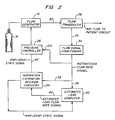
- In an alternative embodiment of the invention as shown in Figs. 2 and 3, the
low pass filter 38 is replaced by an estimated leak computer which includes a low pass filter as well as other functional elements as shown in Fig. 3. The remainder of the system as shown in Fig. 2 is similar in most respects to the system shown in Fig. 1. Accordingly, like elements are identified by like numbers, and the description hereinabove of Fig. 1 embodiment also applies generally to Fig. 2. - By using the operative capability of the estimated
leak computer 50, as described hereinbelow, it is possible to adjust the reference signal which is fed todecision circuitry 34 on a breath by breath basis rather than merely relying on long term average system flow. To distinguish this new reference signal from average system flow it will be referred to hereinbelow as the estimated leak flow rate signal or just the estimated leak signal. - As was noted hereinabove, the average system flow rate reference signal changes very slowly due to the long time constant of the
low pass filter 38. This operative feature was intentionally incorporated to avoid disturbance of the reference signal by aberrant instantaneous flow rate signal inputs such as erratic breathing patterns. While it was possible to minimize the impact of such aberrations on the average flow rate reference signal, the average flow signal did nevertheless change, although by small increments and only very slowly in response to disturbances. Due to the long time constant of the low pass filter, such changes in the reference signal even if transitory could last for a long time. - Additionally, even a small change in the reference signal could produce a very significant effect on system triggering. For example, since the objective is to trigger the system to the IPAP mode when inhalation flow just begins to go positive, small changes in the reference signal could result in relatively large changes in the breathing effort needed to trigger the system to the IPAP mode. In some instances the change in reference signal could be so great that with normal breathing effort the patient would be unable to trigger the system. For example, if the system were turned on before placement of the mask on the face of the patient, the initial free flow of air from the unattached mask could result in a very large magnitude positive value for initial average system flow. If such value were to exceed the maximum inspiratory flow rate achieved in spontaneous respiration by the patient, the system would never trigger between the IPAP and EPAP modes because the decision circuitry would never see an instantaneous flow rate signal greater than the average flow rate signal, at least not until a sufficient number of normal breathing cycles after application of the mask to the patient to bring the reference signal down to a value more closely commensurate with the actual system leak in operation. As has been noted, with the low pass filter this could take a rather long time, during which time the patient would be breathing spontaneously against a uniform positive pressure. This would be tantamount to conventional CPAP and not at all in keeping with the present invention.
- In addition to the embodiment based on a reference signal derived from estimated leak flow rate on a breath by breath basis which is controlled totally by spontaneous patient breathing, two further modes of operation also are envisioned, one being spontaneous/timed operation in which the system automatically triggers to the IPAP mode for just long enough to initiate patient inspiration if the system does not sense inspiratory effort within a selected time after exhalation begins. To accomplish this, a timer is provided which is reset at the beginning of each patient inspiration whether the inspiratory cycle was triggered spontaneously or by the timer itself. Thus, only the start of inspiration is initiated by the timer. The rest of the operating cycle in this mode is controlled by spontaneous patient breathing and the circuitry of the system to be described.
- A further mode of operation is based purely on timed operation of the system rather than on spontaneous patient breathing effort, but with the timed cycles coordinated to spontaneous patient breathing.
- Referring to Fig. 3, the estimated
leak computer 50 includes thelow pass filter 38′ as well as other circuits which are operative to make corrections to the estimated leak flow rate signal based on on-going analysis of each patient breath. A further circuit is provided which is operative to adjust the estimated leak flow rate signal quickly after major changes in system flow such as when the blower has been running prior to the time when the mask is first put on the patient, or after a major leak the system has either started or has been shut off. - The
low pass filter 38′ also includes a data storage capability whose function will be described hereinbelow. - The
low pass filter 38′ operates substantially as described above with reference to Fig. 1 in that it provides a long term average of system flow which is commensurate with steady state system leakage including the flow capacity of theexhaust port 24. This long term average is operative in the Fig. 3 embodiment to adjust the estimated leak flow rate reference signal only when system flow conditions are changing very slowly. - To provide breath by breath analysis and adjustment of the reference signal, a differential amplifier 52 receives the instantaneous flow rate signal as indicated at 54, and the estimated leak signal output from
low pass filter 38′ as indicated at 56. - The output of differential amplifier 52 is the difference between instantaneous flow rate and estimated leak flow rate, or in other words estimated instantaneous patient flow rate. This will be clear upon considering that instantaneous flow is the sum of patient flow plus actual system leakage. The estimated patient flow signal output from differential amplifier 52 is provided as indicated at 58 to a
flow integrator 60 which integrates estimated patient flow breath by breath beginning and ending with the trigger to IPAP. Accordingly, an additional input to theflow integrator 60 is the IPAP/EPAP state signal as indicated at 62. The IPAP/EPAP state signal is the same as the drive signal provided to pressurecontroller 26; that is, it is a signal indicative of the pressure state, as between IPAP and EPAP, of the system. The state signal thus may be used to mark the beginning and end of each breath for purposes of breath by breath integration byintegrator 60. - If the estimated leak flow rate signal from
low pass filter 38′ is equal to the true system leak flow rate, and if the patient's inhaled and exhaled volumes are identical for a given breath (i.e. total positive patient flow equals total negative patient flow for a given breath), then the integral calculated byintegrator 60 will be zero and no adjustment of estimated leak flow rate will result. When the integral calculated byintegrator 60 is non-zero, the integral value in the form of an output signal fromintegrator 60 is provided as indicated at 64 to a sample and holdmodule 66. Of course, even with a zero value integral, an output signal may be provided tomodule 66, but the ultimate result will be no adjustment of the estimated leak flow rate signal. - A non-zero integral value provided to
module 66 is further provided tomodule 38′ as indicated at 68 with each patient breath by operative action of the IPAP/EPAP state signal uponmodule 66 as indicated at 70. The effect of a non-zero integral value provided tomodule 38′ is an adjustment of the estimated leak flow rate signal proportional to the integral value and in the direction which would reduce the integral value towards zero on the next breath if all other conditions remain the same. - With this system, if the patient's net breathing cycle volume is zero, and if the system leak flow rate changes, the integrator circuit will compensate for the change in leak flow rate by incremental adjustments to the estimated leak flow rate within about ten patient breaths.
- The
integrator circuit 60 also will adjust the estimated leak flow rate signal in response to non-zero net volume in a patient breathing cycle. It is not unusual for a patient's breathing volume to be non-zero. For example, a patient may inhale slightly more on each breath than he exhales over several breathing cycles, and then follow with a deeper or fuller exhalation. In this case, the integrator circuit would adjust the estimated leak flow rate signal as if the actual system leak rate had changed; however, since the reference signal correction is only about one tenth as large as would be required to make the total correction in one breath, the reference signal will not change appreciably over just one or two breaths. Thus, the integrator circuit accommodates both changes in system leakage and normal variations in patient breathing patterns. The integrator circuit normally would be active, for example, during rapid patient breathing. - An
end exhalation module 74 is operative to calculate another data component for use in estimating the system leak flow rate as follows. Themodule 74 monitors the slope of the instantaneous flow rate wave form. When the slope value is near zero during exhalation (as indicated by the state signal input 76) the indication is that the flow rate is not changing. If the slope of the instantaneous flow rate signal wave form remains small after more than one second into the respiratory phase, the indication is that exhalation has ended and that the net flow rate at this point thus is the leak flow rate. However, if estimated patient flow rate is non-zero at the same time, one component of the instantaneous flow rate signal must be patient flow. - When these conditions are met, the circuit adjusts the estimated leak flow rate slowly in a direction to move estimated patient flow rate toward zero to conform to instantaneous patient flow conditions expected at the end of exhalation. The adjustment to estimated leak flow rate is provided as an output from
module 74 tolow pass filter 38′ as indicated at 80. When this control mechanism takes effect, it disables the breath by breath volume correction capability ofintegrator circuit 60 for that breath only. - The output of
module 74 is a time constant control signal which is provided tolow pass filter 38′ to temporarily shorten the time constant thereof for a sufficient period to allow the estimated leak flow rate to approach the instantaneous flow rate signal at that specific instant. It will be noted that shortening the low pass filter time constant increases the rapidity with which the low pass filter output (a system average) can adjust toward the instantaneous flow rate signal input. - Another component of estimated leak flow rate control is a
gross error detector 82 which acts when the estimated patient flow rate, provided thereto as indicated at 84, is away from zero for more than about 5 seconds. Such a condition may normally occur, for example, when theflow generator 14 is running beforemask 22 is applied to the patient. This part of the control system is operative to stabilize operation quickly after major changes in the leak rate occur. - In accordance with the above description, it will be seen that
low pass filter 38′ acts on the instantaneous flow rate signal to provide an output corresponding to average system flow, which is system leakage since patient inspiration and expiration over time constitutes a net positive flow of zero. With other enhancements, as described, the system average flow can be viewed as an estimate of leakage flow rate. - The differential amplifier 52 processes the instantaneous flow rate signal and the estimated leak flow rate signal to provide an estimated patient flow rate signal which is integrated and non-zero values of the integral are fed back to
module 38′ to adjust the estimated leak flow rate signal on a breath by breath basis. Theintegrator 60 is reset by the IPAP/EPAP state signal viaconnection 62. - Two circuits are provided which can override the integrator circuit, including
end exhalation detector 74 which provides an output to adjust the time constant oflow pass filter 38′ and which also is provided as indicated at 86 to resetintegrator 60.Gross error detector 82 is also provided to process estimated patient flow rate and to provide an adjustment to estimated leak flow rate under conditions as specified. The output ofmodule 82 also is utilized as an integrator reset signal as indicated at 86. It will be noted that theintegrator 60 is reset with each breath of the patient if, during that breath, it is ultimately overridden bymodule integrator 60 as described are required. - In operation, the system may be utilized in a spontaneous triggering mode, a spontaneous/timed mode or a purely timed mode of operation. In spontaneous operation,
decision circuitry 34 continuously compares the instantaneous flow rate with estimated leak flow rate. If the system is in the EPAP state or mode, it remains there until instantaneous flow rate exceeds estimated leak flow rate by approximately 40 cc per second. When this transition occurs,decision circuitry 34 triggers the system into the IPAP mode for 150 milliseconds. The system will then normally remain in the IPAP mode as the instantaneous flow rate to the patient will continue to increase during inhalation due to spontaneous patient effort and the assistance of the increased IPAP pressure. - After the transition to the IPAP mode in each breath, a temporary offset is added to the estimated leak flow rate reference signal. The offset is proportional to the integral of estimated patient flow rate beginning at initiation of the inspiratory breath so that it gradually increases with time during inspiration at a rate proportional to the patient's inspiratory flow rate. Accordingly, the flow rate level above estimated leak flow needed to keep the system in the IPAP mode during inhalation decreases with time from the beginning of inhalation and in proportion to the inspiratory flow rate. With this enhancement,the longer an inhalation cycle continues, the larger is the reference signal below which instantaneous flow would have to decrease in order to trigger the EPAP mode. For example, if a patient inhales at a constant 500 cc per second until near the end of inspiration, a transition to EPAP will occur when his flow rate drops to about 167 cc per second after one second, or 333 cc per second after two seconds, or 500 cc per second after three seconds, and so forth. For a patient inhaling at a constant 250 cc per second, the triggers would occur at 83, 167 and 250 cc per second at one, two and three seconds into IPAP, respectively.
- In this way, the EPAP trigger threshold comes up to meet the inspiratory flow rate with the following benefits. First, it becomes easier and easier to end the inspiration cycle with increasing time into the cycle. Second, if a leak develops which causes an increase in instantaneous flow sufficient to trigger the system into the IPAP mode, this system will automatically trigger back to the EPAP mode after about 3.0 seconds regardless of patient breathing effort. This would allow the volume-based leak correction circuit (i.e. integrator 60) to act as it is activated with each transition to the IPAP mode. Thus, if a leak develops suddenly, there will be a tendency toward automatic triggering rather than spontaneous operation for a few breaths, but the circuit will not be locked into the IPAP mode.
- Upon switching back to the EPAP mode, the trigger threshold will remain above the estimated leak flow rate for approximately 500 milliseconds to allow the system to remain stable in the EPAP mode without switching again while the respective flow rates are changing. After 500 milliseconds, the trigger threshold offset is reset to zero to await the next inspiratory effort.
- The normal state for the circuit is for it to remain in the EPAP mode until an inspiratory effort is made by the patient. The automatic corrections and adjustments to the reference signal are effective to keep the system from locking up in the IPAP mode and to prevent auto-triggering while at the same time providing a high level of sensitivity to inspiratory effort and rapid adjustment for changing leak conditions and breathing patterns.
- In the spontaneous/timed mode of operation, the system performs exactly as above described with reference to spontaneous operation, except that it allows selection of a minimum breathing rate to be superimposed upon the spontaneous operating mode. If the patient does not make an inspiratory effort within a predetermined time, the system will automatically trigger to the IPAP mode for 200 milliseconds. The increased airway pressure for this 200 milliseconds will initiate patent inspiration and provide sufficient time that spontaneous patient flow will exceed the reference signal so that the rest of the cycle may continue in the spontaneous mode as above described. The breaths per minute timer is reset by each trigger to IPAP whether the transition was triggered by the patient or by the timer itself.
- In the timed operating mode, all triggering between IPAP and EPAP modes is controlled by a timer with a breath per minute control being used to select a desired breathing rate from, for example, 3 to 30 breaths per minute. If feasible, the selected breathing rate is coordinated to the patient's spontaneous breathing rate. The percent IPAP control is used to set the fraction of each breathing cycle to be spent in the IPAP mode. For example, if the breaths per minute control is set to 10 breaths per minute (6 seconds per breath) and the percent IPAP control is set to 33%, then the flow generator will spend, in each breathing cycle, two seconds in IPAP and four seconds in EPAP.
- Fig. 4 illustrates a control panel for controlling the system above described and including a function selector switch which includes function settings for the three operating modes of spontaneous, spontaneous/timed, and timed as above described. The controls for spontaneous mode operation include IPAP and EPAP pressure adjustment controls 90 and 92, respectively. These are used for setting the respective IPAP and EPAP pressure levels. In the spontaneous/timed mode of operation, controls 90 and 92 are utilized as before to set IPAP and EPAP pressure levels, and breaths per
minute control 94 additionally is used to set the minimum desired breathing rate in breaths per minute. In the timed mode of operation, controls 90, 92 and 94 are effective, and in addition the percent IPAP control 96 is used to set the time percentage of each breath to be spent in the IPAP mode. - Lighted indicators such as LED's 97, 98 and 100 are also provided to indicate whether the system is in the IPAP or EPAP state, and to indicate whether in the spontaneous/timed mode of operation the instantaneous state of the system is spontaneous operation or timed operation.
- According to the above description there is provided by the instant invention a novel apparatus for the treatment of sleep apnea. Of course, we have contemplated various alternative and modified embodiments of the invention of which the above described are exemplary as the presently contemplated best modes for carrying out the invention. Such alternative embodiments would also surely occur to others skilled in the art, once apprised of the invention. For example, it may be desirable to provide a flow compensation signal to pressure
controller 26 as indicated at 102 in Fig. 2 to compensate for flow resistance inherent in the circuit; a non-rebreathing valve may be utilized in lieu ofexhaust port 24 atmask 22; and the like.
Claims (15)
- Apparatus for delivering gas to and from the airway of a patient under the control of a controller (26) for controlling the pressure of the said gas during both inhalation and exhalation, characterized by
a first processor (30) for providing an instantaneous flow rate signal (32/36) proportional to the instantaneous flow rate of the said gas during inhalation and exhalation;
a second processor (38) for providing a reference signal (40) representing system leakage derived from said instantaneous flow rate signal (32/36),
and a comparator (34) for comparing the instantaneous flow rate and reference signals (32/36 and 40), and for providing a drive signal (42) for the pressure controller (26). - Apparatus according to claim 1, in which the drive signal identifies voluntary inspiration and expiration phases of a patient's respiration cycle, and is connected to drive the controller to provide a higher pressure of the said gas during inspiration than during expiration.
- Apparatus according to claim 1 or claim 2, in which the first processor (30) comprises a flow transducer (28) and a flow signal conditioner (30).
- Apparatus according to any preceding claim, in which the second processor comprises a low pass filter (38) providing an output signal (40) which approximates to average system leakage.
- Apparatus according to any of claims 1 to 3, in which the second processor (38') is part of an estimated leak computer (50) providing an output signal (40) representing estimated system leakage.
- Apparatus according to claim 5, in which the computer (50) comprises a differential amplifier (52) for producing an estimated patient flow rate signal (58) from the instantaneous flow rate signal (36) and the reference signal (40).
- Apparatus according to claim 6, in which the computer (50) further comprises a single breath flow integrator (60) for the estimated patient flow rate signal (58), triggered by the drive signal (42), for providing an output signal (64) representing the difference between the patient's inhaled and exhaled volumes for a single breathing cycle.
- Apparatus according to claim 7, in which the computer (50) further comprises a sample and hold module (66), also triggered by the drive signal (42), for receiving once per breathing cycle, an output signal (64) from the integrator (60) and delivering that signal as a bias signal (68) to the second processor (38').
- Apparatus according to claim 8, wherein the bias signal (68) is of a size and sign to spread, over several breathing cycles, a change in the estimated system leakage output signal (40) that would otherwise be attributable to the difference between the patient's inhaled and exhaled volumes for that single breathing cycle.
- Apparatus according to any of claims 5 to 9, in which the computer (50) further comprises an end exhalation module (74) to monitor the slope of the instantaneous flow rate wave form and produce a time constant control signal (80) to the second processor (38'), the control signal (80) being responsive to a continuing small slope of the instantaneous flow rate wave form after a predetermined time into the respiratory cycle, and in those conditions being effective to shorten the time constant of a low pass filter circuit of the second processor (38'), thereby to cause the estimated system leakage output signal (40) to approach the instantaneous flow rate signal (36), and to move the estimated patient flow rate signal (58) towards zero.
- Apparatus according to any of claims 5 to 10, in which the computer (50) comprises a gross error detector (82) for stabilizing operation quickly after a major change in the estimated system leakage output signal (40).
- Apparatus according to any of claims 5 to 11, wherein the comparator (34) compares the difference between the instantaneous flow rate and reference signals (32/36 and 40) and a threshold value of approximately 40 cc per second, and provides a drive signal to the controller (26) to increase the pressure of the gas for a trigger period of 150 milliseconds when, during patient exhalation, the difference exceeds the threshold.
- Apparatus according to any of claims 5 to 12, further comprising means, effective during each inhalation phase of the breathing cycle, for adding to the estimated system leakage output signal (40) an offset proportional to the integral of estimated patient flow rate commencing at the initiation of the inspiratory breath, so that the flow rate level above estimated leak flow needed to keep the system from triggering the drive signal (42) from lowering the patient airway pressure decreases with time from the beginning of inhalation and in proportion to the inspiratory flow rate.
- Apparatus according to any preceding claim, further comprising a timed override for the comparator (34), permitting a minimum breathing rate of the patient to be superimposed by automatic timed switching of the drive signal (42) from a first signal state to a second signal state whenever the comparator (34) has not made that transition within a predetermined time.
- Apparatus according to any of claims 1 to 13, further comprising a timed override for the comparator (34), permitting a preset breathing rate of the patient to be imposed by automatic timed switching of the drive signal (42) between first and second signal states for as long as the override is imposed.
Applications Claiming Priority (2)
| Application Number | Priority Date | Filing Date | Title |
|---|---|---|---|
| US07411012 US5148802B1 (en) | 1989-09-22 | 1989-09-22 | Method and apparatus for maintaining airway patency to treat sleep apnea and other disorders |
| US411012 | 1989-09-22 |
Publications (2)
| Publication Number | Publication Date |
|---|---|
| EP0425092A1 EP0425092A1 (en) | 1991-05-02 |
| EP0425092B1 true EP0425092B1 (en) | 1995-08-16 |
Family
ID=23627190
Family Applications (1)
| Application Number | Title | Priority Date | Filing Date |
|---|---|---|---|
| EP90310357A Expired - Lifetime EP0425092B1 (en) | 1989-09-22 | 1990-09-21 | Apparatus for delivering gas to a patient |
Country Status (8)
| Country | Link |
|---|---|
| US (3) | US5148802B1 (en) |
| EP (1) | EP0425092B1 (en) |
| JP (1) | JPH0716517B2 (en) |
| AU (2) | AU695046B2 (en) |
| CA (1) | CA2024477C (en) |
| DE (2) | DE69021681T2 (en) |
| ES (1) | ES2034923T3 (en) |
| FI (1) | FI105651B (en) |
Cited By (11)
| Publication number | Priority date | Publication date | Assignee | Title |
|---|---|---|---|---|
| US6363270B1 (en) | 1995-04-11 | 2002-03-26 | Resmed Limited | Monitoring the occurrence of apneic and hypopneic arousals |
| US6367474B1 (en) | 1997-11-07 | 2002-04-09 | Resmed Limited | Administration of CPAP treatment pressure in presence of APNEA |
| US6397841B1 (en) | 1997-06-18 | 2002-06-04 | Resmed Limited | Apparatus for supplying breathable gas |
| US6526974B1 (en) | 1995-09-18 | 2003-03-04 | John William Ernest Brydon | Pressure control in CPAP treatment or assisted respiration |
| US6532957B2 (en) | 1996-09-23 | 2003-03-18 | Resmed Limited | Assisted ventilation to match patient respiratory need |
| WO2005065757A1 (en) * | 2004-01-07 | 2005-07-21 | Resmed Ltd | Methods for providing expiratory pressure relief in positive airway pressure therapy |
| US8267085B2 (en) | 2009-03-20 | 2012-09-18 | Nellcor Puritan Bennett Llc | Leak-compensated proportional assist ventilation |
| US8272380B2 (en) | 2008-03-31 | 2012-09-25 | Nellcor Puritan Bennett, Llc | Leak-compensated pressure triggering in medical ventilators |
| US8418691B2 (en) | 2009-03-20 | 2013-04-16 | Covidien Lp | Leak-compensated pressure regulated volume control ventilation |
| US8424521B2 (en) | 2009-02-27 | 2013-04-23 | Covidien Lp | Leak-compensated respiratory mechanics estimation in medical ventilators |
| US8746248B2 (en) | 2008-03-31 | 2014-06-10 | Covidien Lp | Determination of patient circuit disconnect in leak-compensated ventilatory support |
Families Citing this family (369)
| Publication number | Priority date | Publication date | Assignee | Title |
|---|---|---|---|---|
| US5199424A (en) * | 1987-06-26 | 1993-04-06 | Sullivan Colin E | Device for monitoring breathing during sleep and control of CPAP treatment that is patient controlled |
| US5522382A (en) | 1987-06-26 | 1996-06-04 | Rescare Limited | Device and method for treating obstructed breathing having a delay/ramp feature |
| US5259373A (en) * | 1989-05-19 | 1993-11-09 | Puritan-Bennett Corporation | Inspiratory airway pressure system controlled by the detection and analysis of patient airway sounds |
| US5148802B1 (en) * | 1989-09-22 | 1997-08-12 | Respironics Inc | Method and apparatus for maintaining airway patency to treat sleep apnea and other disorders |
| US5632269A (en) * | 1989-09-22 | 1997-05-27 | Respironics Inc. | Breathing gas delivery method and apparatus |
| US5239995A (en) * | 1989-09-22 | 1993-08-31 | Respironics, Inc. | Sleep apnea treatment apparatus |
| US5101820A (en) * | 1989-11-02 | 1992-04-07 | Christopher Kent L | Apparatus for high continuous flow augmentation of ventilation and method therefor |
| US5161525A (en) * | 1990-05-11 | 1992-11-10 | Puritan-Bennett Corporation | System and method for flow triggering of pressure supported ventilation |
| ES2075875T3 (en) * | 1990-12-20 | 1995-10-16 | Siemens Ag | BREATHING APPARATUS WITH PATIENT GAS FLOW DEPENDENT SENSITIVITY. |
| US5265593A (en) * | 1991-05-02 | 1993-11-30 | Odland Rick M | Balloon-tipped catheter ventilation system and method for using same having rhythmically inflated and deflated balloon |
| US6085747A (en) * | 1991-06-14 | 2000-07-11 | Respironics, Inc. | Method and apparatus for controlling sleep disorder breathing |
| US5458137A (en) * | 1991-06-14 | 1995-10-17 | Respironics, Inc. | Method and apparatus for controlling sleep disorder breathing |
| US6629527B1 (en) * | 1991-10-17 | 2003-10-07 | Respironics, Inc. | Sleep apnea treatment apparatus |
| US5477852A (en) * | 1991-10-29 | 1995-12-26 | Airways Ltd., Inc. | Nasal positive airway pressure apparatus and method |
| US5687715A (en) * | 1991-10-29 | 1997-11-18 | Airways Ltd Inc | Nasal positive airway pressure apparatus and method |
| US7013892B2 (en) * | 1991-11-01 | 2006-03-21 | Ric Investments, Llc | Sleep apnea treatment apparatus |
| DE69231157T2 (en) * | 1991-11-14 | 2001-02-15 | Univ Technologies Int | AUTOMATIC SYSTEM FOR GENERATING CONTINUOUS POSITIVE AIRWAY PRESSURE |
| EP0549299B1 (en) | 1991-12-20 | 2002-03-13 | Resmed Limited | Ventilator for continuous positive airway pressure breathing (CPAP) |
| US5385142A (en) * | 1992-04-17 | 1995-01-31 | Infrasonics, Inc. | Apnea-responsive ventilator system and method |
| US5803066A (en) * | 1992-05-07 | 1998-09-08 | New York University | Method and apparatus for optimizing the continuous positive airway pressure for treating obstructive sleep apnea |
| US5335654A (en) * | 1992-05-07 | 1994-08-09 | New York University | Method and apparatus for continuous adjustment of positive airway pressure for treating obstructive sleep apnea |
| US5490502A (en) * | 1992-05-07 | 1996-02-13 | New York University | Method and apparatus for optimizing the continuous positive airway pressure for treating obstructive sleep apnea |
| CA2096302A1 (en) * | 1992-05-15 | 1993-11-16 | David Kilis | Air flow controller and recording system |
| WO1993024169A1 (en) * | 1992-06-01 | 1993-12-09 | Cotner Ronald L | Demand positive pressure airway system for apnea treatment |
| US5645054A (en) * | 1992-06-01 | 1997-07-08 | Sleepnet Corp. | Device and method for the treatment of sleep apnea syndrome |
| US5343878A (en) * | 1992-06-08 | 1994-09-06 | Respironics Inc. | Pressure application method |
| FR2692152B1 (en) * | 1992-06-15 | 1997-06-27 | Pierre Medical Sa | BREATHING AID, PARTICULARLY FOR TREATING SLEEP APNEA. |
| FR2694697B1 (en) * | 1992-08-12 | 1994-10-14 | Sefam | Respiratory assistance device. |
| FR2695320B1 (en) * | 1992-09-04 | 1994-12-09 | Sefam | Method for regulating the pressure of an air flow and respiratory assistance device implementing said method. |
| FR2695830B1 (en) * | 1992-09-18 | 1994-12-30 | Pierre Medical Sa | Breathing aid device. |
| US5353788A (en) * | 1992-09-21 | 1994-10-11 | Miles Laughton E | Cardio-respiratory control and monitoring system for determining CPAP pressure for apnea treatment |
| US5517983A (en) * | 1992-12-09 | 1996-05-21 | Puritan Bennett Corporation | Compliance meter for respiratory therapy |
| US5438980A (en) * | 1993-01-12 | 1995-08-08 | Puritan-Bennett Corporation | Inhalation/exhalation respiratory phase detection circuit |
| US5685296A (en) * | 1993-07-30 | 1997-11-11 | Respironics Inc. | Flow regulating valve and method |
| US5398676A (en) * | 1993-09-30 | 1995-03-21 | Press; Roman J. | Portable emergency respirator |
| EP2113196A3 (en) * | 1993-11-05 | 2009-12-23 | ResMed Limited | Control of CPAP treatment |
| US6675797B1 (en) | 1993-11-05 | 2004-01-13 | Resmed Limited | Determination of patency of the airway |
| DE4338813C1 (en) * | 1993-11-15 | 1995-02-23 | Metrax Gmbh | Respirator |
| DE69422900T2 (en) | 1993-12-01 | 2000-06-08 | Resmed Ltd | Continuous positive airway pressure (CPAP) device |
| US5429123A (en) * | 1993-12-15 | 1995-07-04 | Temple University - Of The Commonwealth System Of Higher Education | Process control and apparatus for ventilation procedures with helium and oxygen mixtures |
| FR2714837B1 (en) * | 1994-01-12 | 1996-09-06 | Saime | Device for assisting the ventilation of a patient, comprising in particular a volumetric inspiratory assistance mode. |
| ATE178498T1 (en) * | 1994-01-12 | 1999-04-15 | Saime Sarl | VENTILATORY USING A LOW PRESSURE RESPIRATORY SUPPORT METHOD |
| US6105575A (en) * | 1994-06-03 | 2000-08-22 | Respironics, Inc. | Method and apparatus for providing positive airway pressure to a patient |
| US6932084B2 (en) * | 1994-06-03 | 2005-08-23 | Ric Investments, Inc. | Method and apparatus for providing positive airway pressure to a patient |
| US5535738A (en) * | 1994-06-03 | 1996-07-16 | Respironics, Inc. | Method and apparatus for providing proportional positive airway pressure to treat sleep disordered breathing |
| US5794615A (en) * | 1994-06-03 | 1998-08-18 | Respironics, Inc. | Method and apparatus for providing proportional positive airway pressure to treat congestive heart failure |
| AU683753B2 (en) * | 1994-07-06 | 1997-11-20 | Teijin Limited | An apparatus for assisting in ventilating the lungs of a patient |
| SE503155C2 (en) * | 1994-07-28 | 1996-04-01 | Comasec International Sa | Methods and apparatus for functional control of breathing apparatus |
| FI954092A (en) * | 1994-09-08 | 1996-03-09 | Weinmann G Geraete Med | Method of controlling a respirator in the treatment of sleep apnea |
| DE4432219C1 (en) * | 1994-09-10 | 1996-04-11 | Draegerwerk Ag | Automatic breathing system for patients |
| FR2724322A1 (en) * | 1994-09-12 | 1996-03-15 | Pierre Medical Sa | PRESSURE CONTROLLED BREATHING AID |
| US6866040B1 (en) * | 1994-09-12 | 2005-03-15 | Nellcor Puritan Bennett France Developpement | Pressure-controlled breathing aid |
| US5596984A (en) * | 1994-09-12 | 1997-01-28 | Puritan-Bennett Corporation | Lung ventilator safety circuit |
| US5632270A (en) * | 1994-09-12 | 1997-05-27 | Puritan-Bennett Corporation | Method and apparatus for control of lung ventilator exhalation circuit |
| WO1996011717A1 (en) | 1994-10-14 | 1996-04-25 | Bird Products Corporation | Portable drag compressor powered mechanical ventilator |
| US5503146A (en) * | 1994-10-26 | 1996-04-02 | Devilbiss Health Care, Inc. | Standby control for CPAP apparatus |
| US5551419A (en) * | 1994-12-15 | 1996-09-03 | Devilbiss Health Care, Inc. | Control for CPAP apparatus |
| US5540219A (en) * | 1995-01-26 | 1996-07-30 | Respironics, Inc. | Sleep apnea treatment apparatus |
| US5537997A (en) * | 1995-01-26 | 1996-07-23 | Respironics, Inc. | Sleep apnea treatment apparatus and passive humidifier for use therewith |
| US5947115A (en) * | 1995-01-26 | 1999-09-07 | Respironics, Inc. | Gas flow pressure filter |
| US5598838A (en) * | 1995-04-07 | 1997-02-04 | Healthdyne Technologies, Inc. | Pressure support ventilatory assist system |
| US5937855A (en) * | 1995-04-21 | 1999-08-17 | Respironics, Inc. | Flow regulating valve in a breathing gas delivery system |
| US5598837A (en) * | 1995-06-06 | 1997-02-04 | Respironics, Inc. | Passive humidifier for positive airway pressure devices |
| AUPN344195A0 (en) * | 1995-06-08 | 1995-07-06 | Rescare Limited | Monitoring of oro-nasal respiration |
| AUPN394895A0 (en) | 1995-07-03 | 1995-07-27 | Rescare Limited | Auto-calibration of pressure transducer offset |
| AUPN474195A0 (en) * | 1995-08-09 | 1995-08-31 | Rescare Limited | Apparatus and methods for oro-nasal respiration monitoring |
| US6000396A (en) * | 1995-08-17 | 1999-12-14 | University Of Florida | Hybrid microprocessor controlled ventilator unit |
| AUPN547895A0 (en) | 1995-09-15 | 1995-10-12 | Rescare Limited | Flow estimation and compenstion of flow-induced pressure swings cpap treatment |
| RU2072241C1 (en) | 1995-09-20 | 1997-01-27 | Панина Елена Владимировна | Method and device for preparing inhalation gas mixture |
| AUPN616795A0 (en) * | 1995-10-23 | 1995-11-16 | Rescare Limited | Ipap duration in bilevel cpap or assisted respiration treatment |
| AUPN627395A0 (en) * | 1995-10-31 | 1995-11-23 | Compumedics Sleep Pty Ltd | Integrated diagnostic and therapeutic device for gas delivery to patient |
| US5865173A (en) * | 1995-11-06 | 1999-02-02 | Sunrise Medical Hhg Inc. | Bilevel CPAP system with waveform control for both IPAP and EPAP |
| US5682878A (en) * | 1995-12-07 | 1997-11-04 | Respironics, Inc. | Start-up ramp system for CPAP system with multiple ramp shape selection |
| US6463930B2 (en) | 1995-12-08 | 2002-10-15 | James W. Biondi | System for automatically weaning a patient from a ventilator, and method thereof |
| US6158432A (en) | 1995-12-08 | 2000-12-12 | Cardiopulmonary Corporation | Ventilator control system and method |
| US5832916A (en) * | 1996-02-20 | 1998-11-10 | Interspiro Ab | Method and system for checking the operability of electrical-based components in a breathing equipment |
| US5657752A (en) * | 1996-03-28 | 1997-08-19 | Airways Associates | Nasal positive airway pressure mask and method |
| US5979456A (en) * | 1996-04-22 | 1999-11-09 | Magovern; George J. | Apparatus and method for reversibly reshaping a body part |
| AUPN973596A0 (en) | 1996-05-08 | 1996-05-30 | Resmed Limited | Control of delivery pressure in cpap treatment or assisted respiration |
| US6513526B2 (en) * | 1996-07-26 | 2003-02-04 | Resmed Limited | Full-face mask and mask cushion therefor |
| USD498529S1 (en) | 1996-07-26 | 2004-11-16 | Resmed Limited | Portion of a cushion for use with a mask assembly in the application of continuous positive airway pressure (CPAP) |
| AUPO126596A0 (en) | 1996-07-26 | 1996-08-22 | Resmed Limited | A nasal mask and mask cushion therefor |
| US5705735A (en) * | 1996-08-09 | 1998-01-06 | Medical Graphics Corporation | Breath by breath nutritional requirements analyzing system |
| AU756622B2 (en) * | 1996-08-14 | 2003-01-16 | Resmed Limited | Determination of leak and respiratory airflow |
| AUPO163896A0 (en) * | 1996-08-14 | 1996-09-05 | Resmed Limited | Determination of respiratory airflow |
| US5694923A (en) * | 1996-08-30 | 1997-12-09 | Respironics, Inc. | Pressure control in a blower-based ventilator |
| US5701883A (en) * | 1996-09-03 | 1997-12-30 | Respironics, Inc. | Oxygen mixing in a blower-based ventilator |
| AUPO301796A0 (en) * | 1996-10-16 | 1996-11-07 | Resmed Limited | A vent valve apparatus |
| AU5701498A (en) * | 1996-12-12 | 1998-07-03 | Johns Hopkins University School Of Medicine, The | Method and apparatus for providing ventilatory support to a patient |
| AUPO418696A0 (en) | 1996-12-12 | 1997-01-16 | Resmed Limited | A substance delivery apparatus |
| US5896857A (en) * | 1996-12-20 | 1999-04-27 | Resmed Limited | Valve for use in a gas delivery system |
| AUPO425696A0 (en) | 1996-12-18 | 1997-01-23 | Resmed Limited | A device for preventing or reducing the passage of air through the mouth |
| AUPO504597A0 (en) | 1997-02-10 | 1997-03-06 | Resmed Limited | A mask and a vent assembly therefor |
| US6561191B1 (en) * | 1997-02-10 | 2003-05-13 | Resmed Limited | Mask and a vent assembly therefor |
| AUPO511397A0 (en) | 1997-02-14 | 1997-04-11 | Resmed Limited | An apparatus for varying the flow area of a conduit |
| US5881717A (en) * | 1997-03-14 | 1999-03-16 | Nellcor Puritan Bennett Incorporated | System and method for adjustable disconnection sensitivity for disconnection and occlusion detection in a patient ventilator |
| DE69730748T2 (en) | 1997-05-07 | 2005-09-22 | Compumedics Sleep Pty. Ltd. | DEVICE FOR CONTROLLING GAS OR MEDICINE ADMINISTRATION TO A PATIENT |
| WO1998051362A1 (en) | 1997-05-16 | 1998-11-19 | Peter Craig Farrell | Nasal ventilation as a treatment for stroke |
| DE19738266A1 (en) * | 1997-09-02 | 1999-03-11 | Willi L Schaefer | Apnea mask for use in sleep |
| US5954050A (en) | 1997-10-20 | 1999-09-21 | Christopher; Kent L. | System for monitoring and treating sleep disorders using a transtracheal catheter |
| AUPP015097A0 (en) | 1997-11-03 | 1997-11-27 | Resmed Limited | A mounting body |
| US6192876B1 (en) * | 1997-12-12 | 2001-02-27 | Astra Aktiebolag | Inhalation apparatus and method |
| SE9704643D0 (en) * | 1997-12-12 | 1997-12-12 | Astra Ab | Inhalation apparatus and method |
| US20050121033A1 (en) * | 1998-02-25 | 2005-06-09 | Ric Investments, Llc. | Respiratory monitoring during gas delivery |
| US6017315A (en) | 1998-02-25 | 2000-01-25 | Respironics, Inc. | Patient monitor and method of using same |
| CA2322193C (en) * | 1998-03-05 | 2006-10-24 | Batelle Memorial Institute | Pulmonary dosing system and method |
| USD421298S (en) * | 1998-04-23 | 2000-02-29 | Resmed Limited | Flow generator |
| AUPP366398A0 (en) * | 1998-05-22 | 1998-06-18 | Resmed Limited | Ventilatory assistance for treatment of cardiac failure and cheyne-stokes breathing |
| AUPP370198A0 (en) | 1998-05-25 | 1998-06-18 | Resmed Limited | Control of the administration of continuous positive airway pressure treatment |
| US6564797B1 (en) * | 1998-09-30 | 2003-05-20 | Respironics, Inc. | Interactive pressure support system and method |
| AUPP693398A0 (en) | 1998-11-05 | 1998-12-03 | Resmed Limited | Fault diagnosis in CPAP and NIPPV devices |
| AUPP783198A0 (en) * | 1998-12-21 | 1999-01-21 | Resmed Limited | Determination of mask fitting pressure and correct mask fit |
| EP1140263B1 (en) * | 1999-01-15 | 2011-05-11 | ResMed Limited | Method and apparatus to counterbalance intrinsic positive end expiratory pressure |
| FR2789593B1 (en) * | 1999-05-21 | 2008-08-22 | Mallinckrodt Dev France | APPARATUS FOR SUPPLYING AIR PRESSURE TO A PATIENT WITH SLEEP DISORDERS AND METHODS OF CONTROLLING THE SAME |
| US6467477B1 (en) | 1999-03-26 | 2002-10-22 | Respironics, Inc. | Breath-based control of a therapeutic treatment |
| AUPP996499A0 (en) * | 1999-04-23 | 1999-05-20 | Australian Centre For Advanced Medical Technology Ltd | A treatment for hypertension caused by pre-eclampsia |
| US6135967A (en) | 1999-04-26 | 2000-10-24 | Fiorenza; Anthony Joseph | Respiratory ventilator with automatic flow calibration |
| AUPQ019899A0 (en) | 1999-05-06 | 1999-06-03 | Resmed Limited | Control of supplied pressure in assisted ventilation |
| US6240919B1 (en) * | 1999-06-07 | 2001-06-05 | Macdonald John J. | Method for providing respiratory airway support pressure |
| FR2794635B1 (en) | 1999-06-14 | 2001-08-03 | Taema | APPARATUS FOR DIAGNOSING OR TREATING SLEEP BREATHING DISORDERS AND METHOD OF OPERATION |
| US6895963B1 (en) * | 1999-06-16 | 2005-05-24 | Resmed Limited | Apparatus with automatic respiration monitoring and display |
| US6739335B1 (en) | 1999-09-08 | 2004-05-25 | New York University School Of Medicine | Method and apparatus for optimizing controlled positive airway pressure using the detection of cardiogenic oscillations |
| AU778469B2 (en) * | 1999-09-15 | 2004-12-09 | Resmed Limited | Patient-ventilator synchronization using dual phase sensors |
| US6758216B1 (en) * | 1999-09-15 | 2004-07-06 | Resmed Limited | Ventilatory assistance using an external effort sensor |
| US7225809B1 (en) | 1999-11-01 | 2007-06-05 | Ric Investments, Llc | Method and apparatus for monitoring and controlling a medical device |
| DE10014427A1 (en) * | 2000-03-24 | 2001-10-04 | Weinmann G Geraete Med | Method for controlling a ventilator and device for monitoring |
| US6584977B1 (en) | 2000-04-06 | 2003-07-01 | Respironics, Inc. | Combined patient interface and exhaust assembly |
| US6595212B1 (en) * | 2000-04-17 | 2003-07-22 | Richard J. Arnott | Method and apparatus for maintaining airway patency |
| US6581594B1 (en) * | 2000-05-15 | 2003-06-24 | Resmed Limited | Respiratory mask having gas washout vent and gas washout vent for respiratory mask |
| DE10031079A1 (en) | 2000-06-30 | 2002-02-07 | Map Gmbh | Measuring patient breathing and state, correlates present respiration signals with prior reference measurements, to adjust CPAP therapy pressure accordingly |
| US6532960B1 (en) | 2000-07-10 | 2003-03-18 | Respironics, Inc. | Automatic rise time adjustment for bi-level pressure support system |
| US6814073B2 (en) | 2000-08-29 | 2004-11-09 | Resmed Limited | Respiratory apparatus with improved flow-flattening detection |
| JP2002085568A (en) | 2000-09-21 | 2002-03-26 | Ngk Spark Plug Co Ltd | Oxygen supplier, controller and recording medium therefor |
| JP4293581B2 (en) * | 2000-09-21 | 2009-07-08 | 日本特殊陶業株式会社 | Oxygen concentrator, control device, and recording medium |
| EP1322367A4 (en) | 2000-09-28 | 2009-08-26 | Invacare Corp | Carbon dioxide-based bi-level cpap control |
| US6546930B1 (en) * | 2000-09-29 | 2003-04-15 | Mallinckrodt Inc. | Bi-level flow generator with manual standard leak adjustment |
| US6644310B1 (en) * | 2000-09-29 | 2003-11-11 | Mallinckrodt Inc. | Apparatus and method for providing a breathing gas employing a bi-level flow generator with an AC synchronous motor |
| US6622726B1 (en) * | 2000-10-17 | 2003-09-23 | Newport Medical Instruments, Inc. | Breathing apparatus and method |
| DE10103810A1 (en) | 2001-01-29 | 2002-08-01 | Map Gmbh | Device for supplying a breathing gas |
| US7066175B2 (en) | 2001-05-07 | 2006-06-27 | Emergent Respiratory Products, Inc. | Portable gas powered positive pressure breathing apparatus and method |
| US6851425B2 (en) | 2001-05-25 | 2005-02-08 | Respironics, Inc. | Exhaust port assembly for a pressure support system |
| CA2351217C (en) * | 2001-06-19 | 2008-12-02 | Teijin Limited | An apparatus for supplying a therapeutic oxygen gas |
| FR2826282B1 (en) | 2001-06-22 | 2004-05-28 | Taema | RESPIRATORY APPARATUS WITH STABILIZED PRESSURE TURBINE, TURBINE AND METHOD THEREOF |
| SE0102400D0 (en) * | 2001-07-04 | 2001-07-04 | Siemens Elema Ab | Fluid flow regulation system |
| US7938114B2 (en) * | 2001-10-12 | 2011-05-10 | Ric Investments Llc | Auto-titration bi-level pressure support system and method of using same |
| US7168429B2 (en) * | 2001-10-12 | 2007-01-30 | Ric Investments, Llc | Auto-titration pressure support system and method of using same |
| WO2003041780A2 (en) | 2001-11-16 | 2003-05-22 | Fisher & Paykel Healthcare Limited | A nasal positive pressure device |
| US6892729B2 (en) | 2001-11-20 | 2005-05-17 | Fisher & Paykel Healthcare Limited | Patient interfaces |
| AU2003225926B2 (en) | 2002-03-22 | 2006-09-28 | Invacare Corporation | Nasal mask |
| EP3108919B1 (en) | 2002-12-06 | 2020-09-09 | Fisher & Paykel Healthcare Limited | System for delivery of pressurized gases |
| CA2512843A1 (en) * | 2003-01-09 | 2004-07-29 | The Research Foundation Of State University Of New York | Method of treating functional somatic syndromes and diagnosing sleep disorders based on functional somatic syndrome symptoms |
| FR2850284B1 (en) | 2003-01-27 | 2012-11-30 | Saime Sarl | BREATHING DEVICE AND REGULATION METHOD |
| US7565906B2 (en) * | 2003-04-28 | 2009-07-28 | Ric Investments, Inc. | Pressure/flow control valve and system using same |
| EP1477199A1 (en) * | 2003-05-15 | 2004-11-17 | Azienda Ospedaliera Pisana | Apparatus for non-invasive mechanical ventilation |
| US7588033B2 (en) | 2003-06-18 | 2009-09-15 | Breathe Technologies, Inc. | Methods, systems and devices for improving ventilation in a lung area |
| US7559326B2 (en) | 2003-06-18 | 2009-07-14 | Resmed Limited | Vent and/or diverter assembly for use in breathing apparatus |
| US8020555B2 (en) * | 2003-06-18 | 2011-09-20 | New York University | System and method for improved treatment of sleeping disorders using therapeutic positive airway pressure |
| DE10337138A1 (en) * | 2003-08-11 | 2005-03-17 | Freitag, Lutz, Dr. | Method and arrangement for the respiratory assistance of a patient as well as tracheal prosthesis and catheter |
| AU2003903138A0 (en) * | 2003-06-20 | 2003-07-03 | Resmed Limited | Method and apparatus for improving the comfort of cpap |
| US7621270B2 (en) | 2003-06-23 | 2009-11-24 | Invacare Corp. | System and method for providing a breathing gas |
| US7152598B2 (en) | 2003-06-23 | 2006-12-26 | Invacare Corporation | System and method for providing a breathing gas |
| WO2005004963A2 (en) * | 2003-07-09 | 2005-01-20 | Map Medizin-Technologie Gmbh | Respiratory mask arrangement as well as head band arrangement and respiratory gas evacuation device for a respiratory mask |
| US7114497B2 (en) * | 2003-07-18 | 2006-10-03 | Acoba, Llc | Method and system of individually controlling airway pressure of a patient's nares |
| US7118536B2 (en) * | 2003-07-25 | 2006-10-10 | Ric Investments, Llc. | Apnea/hypopnea detection system and method |
| US6988994B2 (en) * | 2003-08-14 | 2006-01-24 | New York University | Positive airway pressure system and method for treatment of sleeping disorder in patient |
| EP1660004A4 (en) | 2003-08-18 | 2017-05-31 | Breathe Technologies, Inc. | Method and device for non-invasive ventilation with nasal interface |
| US7044129B1 (en) | 2003-09-03 | 2006-05-16 | Ric Investments, Llc. | Pressure support system and method |
| US7343917B2 (en) * | 2003-09-22 | 2008-03-18 | Resmed Limited | Clear cycle for ventilation device |
| US7041049B1 (en) * | 2003-11-21 | 2006-05-09 | First Principles, Inc. | Sleep guidance system and related methods |
| US8011366B2 (en) * | 2004-02-04 | 2011-09-06 | Devilbiss Healthcare Llc | Method for acclimating a CPAP therapy patient to prescribed pressure |
| US8783257B2 (en) | 2004-02-23 | 2014-07-22 | Fisher & Paykel Healthcare Limited | Breathing assistance apparatus |
| EP2388036A3 (en) | 2004-02-25 | 2013-03-13 | ResMed Ltd. | Cardiac monitoring and therapy using a device for providing pressure treatment of sleep disordered breathing |
| DE102004014538A1 (en) * | 2004-03-23 | 2005-10-13 | Seleon Gmbh | Method for controlling a BiLevel device and BiLevel device |
| ES2703450T3 (en) | 2004-04-02 | 2019-03-08 | Fisher & Paykel Healthcare Ltd | Breathing assistance device |
| US9072852B2 (en) | 2004-04-02 | 2015-07-07 | Fisher & Paykel Healthcare Limited | Breathing assistance apparatus |
| AU2005231520B2 (en) | 2004-04-09 | 2011-07-28 | Resmed Limited | Nasal assembly |
| NZ595133A (en) | 2004-04-15 | 2013-06-28 | Resmed Ltd | Headgear for positive air pressure treatment with a bifurcated conduit which compensates for occusion in one side if a patient rolls in their sleep |
| US7267121B2 (en) * | 2004-04-20 | 2007-09-11 | Aerogen, Inc. | Aerosol delivery apparatus and method for pressure-assisted breathing systems |
| GB2413499A (en) * | 2004-04-28 | 2005-11-02 | Newcastle Upon Tyne Hospitals | Leak measurement around an uncuffed endo-tracheal tube |
| US7276031B2 (en) * | 2004-05-12 | 2007-10-02 | New York University | System and method for classifying patient's breathing using artificial neural network |
| US20050268912A1 (en) * | 2004-06-04 | 2005-12-08 | Norman Robert G | System and method for automated titration of continuous positive airway pressure |
| US20060005834A1 (en) * | 2004-07-07 | 2006-01-12 | Acoba, Llc | Method and system of providing therapeutic gas to a patient to prevent breathing airway collapse |
| US7882834B2 (en) * | 2004-08-06 | 2011-02-08 | Fisher & Paykel Healthcare Limited | Autotitrating method and apparatus |
| US20060042627A1 (en) * | 2004-08-31 | 2006-03-02 | Macmillan Nicholas J | PAP titrate control method and apparatus |
| US7717110B2 (en) * | 2004-10-01 | 2010-05-18 | Ric Investments, Llc | Method and apparatus for treating Cheyne-Stokes respiration |
| US20060096596A1 (en) * | 2004-11-05 | 2006-05-11 | Occhialini James M | Wearable system for positive airway pressure therapy |
| US20060174885A1 (en) * | 2005-02-08 | 2006-08-10 | Acoba, Llc | Method and related system to control applied pressure in CPAP systems |
| US7322356B2 (en) * | 2005-02-24 | 2008-01-29 | Restore Medical, Inc. | Combination sleep apnea treatment |
| US7347205B2 (en) * | 2005-08-31 | 2008-03-25 | The General Electric Company | Method for use with the pressure triggering of medical ventilators |
| JP2009508645A (en) | 2005-09-20 | 2009-03-05 | ルッツ フレイテッグ, | System, method and apparatus for assisting patient breathing |
| US8025052B2 (en) * | 2005-11-21 | 2011-09-27 | Ric Investments, Llc | System and method of monitoring respiratory events |
| WO2007062400A2 (en) | 2005-11-23 | 2007-05-31 | Jianguo Sun | Method and apparatus for providing positive airway pressure to a patient |
| NZ607280A (en) | 2006-03-06 | 2014-06-27 | Resmed Ltd | Method and apparatus for improved flow limitation detection of obstructive sleep apnea |
| DE102007011924A1 (en) * | 2006-03-08 | 2007-12-27 | Weinmann Geräte für Medizin GmbH & Co. KG | Method and device for controlling a ventilator |
| JP4224610B2 (en) * | 2006-04-17 | 2009-02-18 | 興研株式会社 | Simulated breathing device for evaluation test of respiratory protective equipment |
| WO2007142812A2 (en) | 2006-05-18 | 2007-12-13 | Breathe Technologies, Inc. | Tracheotomy method and device |
| ES2954589T3 (en) | 2006-07-14 | 2023-11-23 | Fisher & Paykel Healthcare Ltd | Respiratory assistance device |
| NZ567432A (en) | 2006-07-28 | 2012-03-30 | Resmed Ltd | A patient interface system with an interfacing structure including an unskinned foam surface |
| NZ738046A (en) | 2006-07-28 | 2019-06-28 | ResMed Pty Ltd | Delivery of respiratory therapy |
| JP2009545384A (en) | 2006-08-03 | 2009-12-24 | ブリーズ テクノロジーズ, インコーポレイテッド | Method and apparatus for minimally invasive respiratory assistance |
| US8069853B2 (en) * | 2006-08-14 | 2011-12-06 | Immediate Response Technologies | Breath responsive powered air-purifying respirator |
| CN102894979B (en) | 2006-08-30 | 2016-07-06 | 瑞思迈有限公司 | It is worth distinguishing closed and open respiratory airway asphyxia by complex admittance |
| US8322339B2 (en) * | 2006-09-01 | 2012-12-04 | Nellcor Puritan Bennett Llc | Method and system of detecting faults in a breathing assistance device |
| US8316847B2 (en) * | 2006-09-01 | 2012-11-27 | Ventific Holdings Pty Ltd | Automatic positive airway pressure therapy through the nose or mouth for treatment of sleep apnea and other respiratory disorders |
| US20080142013A1 (en) * | 2006-09-11 | 2008-06-19 | Michael David Hallett | Exhaust Apparatus For Use in Administering Positive Pressure Therapy Through the Nose or Mouth |
| US20080060647A1 (en) * | 2006-09-12 | 2008-03-13 | Invacare Corporation | System and method for delivering a breathing gas |
| CA2602005A1 (en) | 2006-09-18 | 2008-03-18 | Invacare Corporation | Breathing mask |
| US20080078385A1 (en) * | 2006-09-29 | 2008-04-03 | Yang Xiao | System and method for delivery of medication via inhalation |
| US20080078389A1 (en) * | 2006-09-29 | 2008-04-03 | Yang Xiao | Heliox delivery system and method with positive pressure support |
| US8205615B1 (en) | 2006-09-29 | 2012-06-26 | Ric Investments, Llc | Self directing exhaust port assembly |
| US20080114618A1 (en) * | 2006-11-03 | 2008-05-15 | Kevin Pysnik | Patient information management system |
| US20080114689A1 (en) * | 2006-11-03 | 2008-05-15 | Kevin Psynik | Patient information management method |
| US10166357B2 (en) | 2006-12-15 | 2019-01-01 | Resmed Limited | Delivery of respiratory therapy with nasal interface |
| CH704346B1 (en) * | 2007-02-05 | 2012-07-13 | Imtmedical Ag | Control valve for ventilators. |
| US8789528B2 (en) * | 2007-02-12 | 2014-07-29 | Ric Investments, Llc | Pressure support method with automatic comfort feature modification |
| US7918226B2 (en) | 2007-04-10 | 2011-04-05 | General Electric Company | Method and system for detecting breathing tube occlusion |
| US20080257348A1 (en) * | 2007-04-20 | 2008-10-23 | Piper S David | Emergency and mass casualty ventilator |
| WO2008144589A1 (en) | 2007-05-18 | 2008-11-27 | Breathe Technologies, Inc. | Methods and devices for sensing respiration and providing ventilation therapy |
| US8794235B2 (en) * | 2007-06-08 | 2014-08-05 | Ric Investments, Llc | System and method for treating ventilatory instability |
| US8261742B2 (en) | 2007-08-23 | 2012-09-11 | Invacare Corporation | Method and apparatus for adjusting desired pressure in positive airway pressure devices |
| US20090078258A1 (en) * | 2007-09-21 | 2009-03-26 | Bowman Bruce R | Pressure regulation methods for positive pressure respiratory therapy |
| US20090078255A1 (en) * | 2007-09-21 | 2009-03-26 | Bowman Bruce R | Methods for pressure regulation in positive pressure respiratory therapy |
| CN101888868B (en) | 2007-09-26 | 2014-01-22 | 呼吸科技公司 | Methods and devices for treating sleep apnea |
| US8567399B2 (en) | 2007-09-26 | 2013-10-29 | Breathe Technologies, Inc. | Methods and devices for providing inspiratory and expiratory flow relief during ventilation therapy |
| BRPI0819992A8 (en) * | 2007-12-04 | 2016-02-10 | Koninklijke Philips Nv | METHODS FOR OPERATING A MEDICAL DEVICE AND ENABLING NUMEROUS OPERATIONAL ASPECTS OF A MEDICAL DEVICE, AND, MEDICAL DEVICE |
| US20090165795A1 (en) * | 2007-12-31 | 2009-07-02 | Nellcor Puritan Bennett Llc | Method and apparatus for respiratory therapy |
| WO2009123981A1 (en) * | 2008-03-31 | 2009-10-08 | Nellcor Puritan Bennett Llc | Leak-compensated proportional assist ventilation |
| US10207069B2 (en) | 2008-03-31 | 2019-02-19 | Covidien Lp | System and method for determining ventilator leakage during stable periods within a breath |
| EP2276535B1 (en) | 2008-04-18 | 2020-05-27 | Breathe Technologies, Inc. | Devices for sensing respiration and controlling ventilator functions |
| WO2009129506A1 (en) | 2008-04-18 | 2009-10-22 | Breathe Technologies, Inc. | Methods and devices for sensing respiration and controlling ventilator functions |
| US8251876B2 (en) | 2008-04-22 | 2012-08-28 | Hill-Rom Services, Inc. | Breathing exercise apparatus |
| US8752546B2 (en) | 2008-04-23 | 2014-06-17 | General Electric Company | System and method for mobilizing occlusions from a breathing tube |
| US8573208B2 (en) * | 2008-05-07 | 2013-11-05 | Koninklijke Philips N.V. | Exhaust assembly |
| US10792451B2 (en) | 2008-05-12 | 2020-10-06 | Fisher & Paykel Healthcare Limited | Patient interface and aspects thereof |
| US10258757B2 (en) | 2008-05-12 | 2019-04-16 | Fisher & Paykel Healthcare Limited | Patient interface and aspects thereof |
| CN102056538B (en) | 2008-06-06 | 2014-10-15 | 柯惠有限合伙公司 | Systems and methods for determining patient effort and/or respiratory parameters in a ventilation system |
| US11660413B2 (en) | 2008-07-18 | 2023-05-30 | Fisher & Paykel Healthcare Limited | Breathing assistance apparatus |
| US8677999B2 (en) | 2008-08-22 | 2014-03-25 | Breathe Technologies, Inc. | Methods and devices for providing mechanical ventilation with an open airway interface |
| US8794234B2 (en) | 2008-09-25 | 2014-08-05 | Covidien Lp | Inversion-based feed-forward compensation of inspiratory trigger dynamics in medical ventilators |
| US8302602B2 (en) | 2008-09-30 | 2012-11-06 | Nellcor Puritan Bennett Llc | Breathing assistance system with multiple pressure sensors |
| JP5711661B2 (en) | 2008-10-01 | 2015-05-07 | ブリーズ・テクノロジーズ・インコーポレーテッド | Ventilator with biofeedback monitoring and controls to improve patient activity and health |
| DK3323462T3 (en) | 2008-10-10 | 2022-01-17 | Fisher & Paykel Healthcare Ltd | NOSE PILLOWS FOR A PATIENT INTERFACE. |
| CN102256649B (en) * | 2008-10-17 | 2014-12-17 | 皇家飞利浦电子股份有限公司 | Porting block for a medical ventilator |
| EP2340596B1 (en) * | 2008-10-17 | 2012-08-15 | Koninklijke Philips Electronics N.V. | Power control in a medical ventilator |
| EP2334360B1 (en) | 2008-10-17 | 2016-12-14 | Koninklijke Philips N.V. | Inlet airflow assembly in a medical ventilator |
| EP2334359B1 (en) | 2008-10-17 | 2020-07-22 | Koninklijke Philips N.V. | Volume control in a medical ventilator |
| JP5575789B2 (en) | 2008-11-19 | 2014-08-20 | インスパイア・メディカル・システムズ・インコーポレイテッド | How to treat sleep-disordered breathing |
| EP2376160B1 (en) * | 2008-12-09 | 2016-06-22 | Koninklijke Philips N.V. | Automatic rise time adjustment |
| US9901692B2 (en) * | 2008-12-19 | 2018-02-27 | Koninklijke Philips N.V. | System and method for treating lung disease using positive pressure airway support |
| JP2012513807A (en) | 2008-12-30 | 2012-06-21 | コーニンクレッカ フィリップス エレクトロニクス エヌ ヴィ | System, method and respiratory device for supporting a subject's airway |
| RU2537062C2 (en) * | 2008-12-30 | 2014-12-27 | Конинклейке Филипс Электроникс Н.В. | System and respiratory device for supporting positive pressure in patients' respiratory ways |
| US9132250B2 (en) | 2009-09-03 | 2015-09-15 | Breathe Technologies, Inc. | Methods, systems and devices for non-invasive ventilation including a non-sealing ventilation interface with an entrainment port and/or pressure feature |
| JP5738201B2 (en) * | 2009-02-11 | 2015-06-17 | レスメド・リミテッドResMedLimited | Acoustic detection for respiratory therapy equipment |
| AU2010217313B2 (en) | 2009-02-25 | 2015-02-19 | Koninklijke Philips Electronics, N.V. | Pressure support system with machine delivered breaths |
| EP2401016B1 (en) | 2009-02-25 | 2020-03-18 | Koninklijke Philips N.V. | Patient-ventilator dyssynchrony detection |
| CA2757588C (en) | 2009-04-02 | 2017-01-03 | Breathe Technologies, Inc. | Methods, systems and devices for non-invasive open ventilation with gas delivery nozzles in free space |
| US9962512B2 (en) | 2009-04-02 | 2018-05-08 | Breathe Technologies, Inc. | Methods, systems and devices for non-invasive ventilation including a non-sealing ventilation interface with a free space nozzle feature |
| EP3351170B1 (en) | 2009-04-22 | 2023-05-31 | ResMed Pty Ltd | Detection of asynchrony |
| US20100288283A1 (en) * | 2009-05-15 | 2010-11-18 | Nellcor Puritan Bennett Llc | Dynamic adjustment of tube compensation factor based on internal changes in breathing tube |
| US8545231B2 (en) * | 2009-06-25 | 2013-10-01 | Charles Richard Lloyd | Obstructive sleep apnea demonstration model device |
| CN102762250B (en) | 2009-09-03 | 2017-09-26 | 呼吸科技公司 | Mthods, systems and devices for including the invasive ventilation with entrainment port and/or the non-tight vented interface of pressure characteristic |
| US8215302B2 (en) * | 2009-09-22 | 2012-07-10 | Kassatly L Samuel A | Discontinuous positive airway pressure device and method of reducing sleep disordered breathing events |
| US8544468B2 (en) * | 2009-10-07 | 2013-10-01 | Richard J. Arnott | System, apparatus and method for maintaining airway patency and pressure support ventilation |
| EP3741418A1 (en) | 2009-11-18 | 2020-11-25 | Fisher & Paykel Healthcare Limited | Nasal interface |
| EP2515981B1 (en) | 2009-12-23 | 2021-08-18 | Fisher & Paykel Healthcare Limited | Patient interface and headgear |
| WO2011080604A1 (en) | 2009-12-28 | 2011-07-07 | Koninklijke Philips Electronics N.V. | Exhaust port assembly that minimizes noise |
| JP5777637B2 (en) | 2010-01-14 | 2015-09-09 | コーニンクレッカ フィリップス エヌ ヴェ | Auxiliary ventilator with pressure drop from baseline |
| US9463293B2 (en) | 2010-01-14 | 2016-10-11 | Koninklijke Philips N.V. | Servo ventilation using negative pressure support |
| AU2010343682B2 (en) | 2010-01-22 | 2015-01-29 | Koninklijke Philips Electronics N.V. | Automatically controlled ventilation system |
| US8707952B2 (en) | 2010-02-10 | 2014-04-29 | Covidien Lp | Leak determination in a breathing assistance system |
| WO2011107909A1 (en) | 2010-03-02 | 2011-09-09 | Koninklijke Philips Electronics N.V. | Helmet-type of patient interface device and method use |
| AU2010201464B2 (en) * | 2010-04-14 | 2014-10-23 | Hallett, Michael | Automatic Positive Airway Pressure Therapy through the Nose or Mouth for Treatment of Sleep Apnea and Other Respiratory Disorders |
| US20130109993A1 (en) | 2010-05-17 | 2013-05-02 | Koninklijke Philips Electronics N.V. | System and method for estimating upper airway resistance and lung compliance employing induced central apneas |
| EP2575944B1 (en) | 2010-06-04 | 2017-02-22 | Koninklijke Philips N.V. | Automatic control of temperature in a patient circuit |
| EP2575945A1 (en) | 2010-06-04 | 2013-04-10 | Koninklijke Philips Electronics N.V. | Automatic humidity control in a pressure support system |
| WO2012024342A1 (en) | 2010-08-16 | 2012-02-23 | Breathe Technologies, Inc. | Methods, systems and devices using lox to provide ventilatory support |
| US20120060835A1 (en) * | 2010-09-13 | 2012-03-15 | General Electric Company | Anesthesia system and method |
| US8939152B2 (en) | 2010-09-30 | 2015-01-27 | Breathe Technologies, Inc. | Methods, systems and devices for humidifying a respiratory tract |
| US10569045B2 (en) | 2010-10-05 | 2020-02-25 | Richard J. Arnott | Apparatus and method for maintaining airway patency and pressure support ventilation |
| WO2012047121A1 (en) | 2010-10-08 | 2012-04-12 | Fisher & Paykel Healthcare Limited | Breathing assistance apparatus |
| US8844537B1 (en) | 2010-10-13 | 2014-09-30 | Michael T. Abramson | System and method for alleviating sleep apnea |
| CN103260682B (en) | 2010-12-20 | 2016-03-16 | 皇家飞利浦电子股份有限公司 | Depend on the Respiration assistance of breathing rate |
| US8991392B1 (en) | 2010-12-21 | 2015-03-31 | Fisher & Paykel Healthcare Limited | Pressure adjustment method for CPAP machine |
| US8783250B2 (en) | 2011-02-27 | 2014-07-22 | Covidien Lp | Methods and systems for transitory ventilation support |
| US9084859B2 (en) | 2011-03-14 | 2015-07-21 | Sleepnea Llc | Energy-harvesting respiratory method and device |
| US8714154B2 (en) | 2011-03-30 | 2014-05-06 | Covidien Lp | Systems and methods for automatic adjustment of ventilator settings |
| CN103561805A (en) * | 2011-03-30 | 2014-02-05 | 皇家飞利浦有限公司 | Methods to transition adjacent to or in conjunction with a secondary airway pressure therapy |
| CA2833106C (en) | 2011-04-15 | 2019-08-27 | Fisher & Paykel Healthcare Limited | Interface comprising a rolling nasal bridge portion |
| US10603456B2 (en) | 2011-04-15 | 2020-03-31 | Fisher & Paykel Healthcare Limited | Interface comprising a nasal sealing portion |
| US8776792B2 (en) | 2011-04-29 | 2014-07-15 | Covidien Lp | Methods and systems for volume-targeted minimum pressure-control ventilation |
| CN103582507B (en) | 2011-05-20 | 2016-05-18 | 皇家飞利浦有限公司 | Rotary electric connector and use the breathing gas induction system of this rotary electric connector |
| WO2013023218A1 (en) | 2011-08-11 | 2013-02-14 | Inspire Medical Systems, Inc. | System for selecting a stimulation protocol based on sensed respiratory effort |
| JP6058676B2 (en) | 2011-09-21 | 2017-01-11 | コーニンクレッカ フィリップス エヌ ヴェKoninklijke Philips N.V. | Upper airway resistance measuring device |
| US9364624B2 (en) | 2011-12-07 | 2016-06-14 | Covidien Lp | Methods and systems for adaptive base flow |
| US9498589B2 (en) | 2011-12-31 | 2016-11-22 | Covidien Lp | Methods and systems for adaptive base flow and leak compensation |
| US9022031B2 (en) | 2012-01-31 | 2015-05-05 | Covidien Lp | Using estimated carinal pressure for feedback control of carinal pressure during ventilation |
| CN104379204A (en) | 2012-02-15 | 2015-02-25 | 费雪派克医疗保健有限公司 | System, apparatus and methods for supplying gases |
| US9180271B2 (en) | 2012-03-05 | 2015-11-10 | Hill-Rom Services Pte. Ltd. | Respiratory therapy device having standard and oscillatory PEP with nebulizer |
| US10213566B2 (en) * | 2012-03-28 | 2019-02-26 | Vapotherm, Inc. | Systems and methods for providing respiratory therapy with varying flow rates |
| US8844526B2 (en) | 2012-03-30 | 2014-09-30 | Covidien Lp | Methods and systems for triggering with unknown base flow |
| US9327089B2 (en) | 2012-03-30 | 2016-05-03 | Covidien Lp | Methods and systems for compensation of tubing related loss effects |
| US9993604B2 (en) | 2012-04-27 | 2018-06-12 | Covidien Lp | Methods and systems for an optimized proportional assist ventilation |
| JP6396892B2 (en) * | 2012-05-14 | 2018-09-26 | レスメド・モーター・テクノロジーズ・インコーポレーテッド | Pressure control for breathing comfort |
| EP2859482A2 (en) | 2012-06-08 | 2015-04-15 | Koninklijke Philips N.V. | Patient sleep therapy self management tool |
| US10362967B2 (en) | 2012-07-09 | 2019-07-30 | Covidien Lp | Systems and methods for missed breath detection and indication |
| CA2880749C (en) | 2012-08-08 | 2022-03-08 | Fisher & Paykel Healthcare Limited | Headgear for patient interface |
| US9950130B2 (en) | 2012-09-04 | 2018-04-24 | Fisher & Paykel Healthcare Limited | Valsalva mask |
| US9878123B2 (en) * | 2012-09-11 | 2018-01-30 | Fisher & Paykel Healthcare Limited | Surgical humidifier control |
| US9375542B2 (en) | 2012-11-08 | 2016-06-28 | Covidien Lp | Systems and methods for monitoring, managing, and/or preventing fatigue during ventilation |
| RU2015129063A (en) | 2012-12-20 | 2017-01-26 | Конинклейке Филипс Н.В. | AUTOMATIC PAIRING OF WIRELESS PERIPHERAL DEVICES WITH A SYSTEM SUCH AS A RESPIRATORY THERAPY SYSTEM WITH PRESSURE SUPPORT |
| RU2676433C2 (en) * | 2012-12-26 | 2018-12-28 | Конинклейке Филипс Н.В. | System and method for limiting flow and/or pressure compensation during limited flow respiratory therapy |
| US9492629B2 (en) | 2013-02-14 | 2016-11-15 | Covidien Lp | Methods and systems for ventilation with unknown exhalation flow and exhalation pressure |
| US9358355B2 (en) | 2013-03-11 | 2016-06-07 | Covidien Lp | Methods and systems for managing a patient move |
| US9981096B2 (en) | 2013-03-13 | 2018-05-29 | Covidien Lp | Methods and systems for triggering with unknown inspiratory flow |
| US10342942B2 (en) | 2013-03-15 | 2019-07-09 | Fisher & Paykel Healthcare Limited | Respiratory assistance device and method of controlling said device |
| WO2014147514A1 (en) | 2013-03-21 | 2014-09-25 | Koninklijke Philips N.V. | A gas delivery system including a flow generator employing a continuously variable transmission |
| US9610417B2 (en) | 2013-05-07 | 2017-04-04 | Gabrielle M Kassatly | Portable discontinuous positive airway pressure (DPAP) device and method of using the same |
| WO2014203104A1 (en) * | 2013-06-19 | 2014-12-24 | Koninklijke Philips N.V. | Determining of subject zero flow using cluster analysis |
| CN105339033B (en) | 2013-06-28 | 2018-02-09 | 皇家飞利浦有限公司 | The humidification device assembly and method of moisture are provided for the supply gas in pressure support system |
| JP6006903B2 (en) | 2013-08-12 | 2016-10-12 | コーニンクレッカ フィリップス エヌ ヴェKoninklijke Philips N.V. | Detection of fit of patient interface device |
| US9675771B2 (en) | 2013-10-18 | 2017-06-13 | Covidien Lp | Methods and systems for leak estimation |
| JP6397915B2 (en) | 2013-12-18 | 2018-09-26 | コーニンクレッカ フィリップス エヌ ヴェKoninklijke Philips N.V. | Gas delivery system and method for disinfecting a gas flow path in the gas delivery system |
| US9808591B2 (en) | 2014-08-15 | 2017-11-07 | Covidien Lp | Methods and systems for breath delivery synchronization |
| WO2016032343A1 (en) | 2014-08-25 | 2016-03-03 | Fisher & Paykel Healthcare Limited | Respiratory mask and related portions, components or sub-assemblies |
| TWI780489B (en) | 2014-09-16 | 2022-10-11 | 紐西蘭商費雪 & 佩凱爾關心健康有限公司 | Intramold headgear |
| US10646680B2 (en) | 2014-09-19 | 2020-05-12 | Fisher & Paykel Healthcare Limited | Headgear assemblies and interface assemblies with headgear |
| US9950129B2 (en) | 2014-10-27 | 2018-04-24 | Covidien Lp | Ventilation triggering using change-point detection |
| US9925346B2 (en) | 2015-01-20 | 2018-03-27 | Covidien Lp | Systems and methods for ventilation with unknown exhalation flow |
| US11497870B2 (en) | 2015-02-24 | 2022-11-15 | Somnetics International, Inc. | Systems and methods for estimating flow in positive airway pressure therapy |
| CN107864617B (en) | 2015-03-19 | 2021-08-20 | 启迪医疗仪器公司 | Stimulation for treating sleep disordered breathing |
| WO2016159889A1 (en) | 2015-04-02 | 2016-10-06 | Hill-Rom Services Pte. Ltd. | Manifold for respiratory device |
| WO2016178114A1 (en) | 2015-05-07 | 2016-11-10 | Koninklijke Philips N.V. | Monitoring the degradation of a component of a patient interface device |
| US10792458B2 (en) | 2015-06-03 | 2020-10-06 | Koninklijke Philips N.V. | Rainout control in a pressure support system |
| CN107847708B (en) | 2015-06-29 | 2021-08-17 | 皇家飞利浦有限公司 | Collapsible humidifier |
| CN107847699A (en) | 2015-06-30 | 2018-03-27 | 皇家飞利浦有限公司 | Baroceptor for adjustable resistance positive airway pressure apparatus compensation of pipeline |
| US11298481B2 (en) | 2015-09-16 | 2022-04-12 | 12th Man Technologies, Inc. | Non-gas analyzer monitor of inspired gas concentration |
| WO2017069756A1 (en) | 2015-10-22 | 2017-04-27 | Honeywell International Inc. | Smart respiratory face mask module |
| US11298074B2 (en) | 2015-12-08 | 2022-04-12 | Fisher & Paykel Healthcare Limited | Flow-based sleep stage determination |
| US20190001090A1 (en) | 2015-12-22 | 2019-01-03 | Koninklijke Philips N.V. | Pressure support device including sensor to detect non-sleep disordered breathing conditions |
| EP3429669B1 (en) | 2016-03-16 | 2022-11-16 | Fisher & Paykel Healthcare Limited | Method for manufacturing a headgear assembly for a respiratory interface |
| EP3430284B1 (en) | 2016-03-16 | 2021-07-14 | Fisher & Paykel Healthcare Limited | Directional lock for interface headgear arrangement |
| AU2017234315C1 (en) | 2016-03-16 | 2023-02-02 | Fisher & Paykel Healthcare Limited | Strap assembly, strap connector, headgear, headgear assembly, method of forming headgear, tubular connector, patient interface and method of joining straps |
| USD882066S1 (en) | 2016-05-13 | 2020-04-21 | Fisher & Paykel Healthcare Limited | Frame for a breathing mask |
| JP7090618B2 (en) | 2016-12-23 | 2022-06-24 | コーニンクレッカ フィリップス エヌ ヴェ | Pressure assist devices and methods to identify changes in the patient circuit |
| USD824020S1 (en) | 2017-02-23 | 2018-07-24 | Fisher & Paykel Healthcare Limited | Cushion assembly for breathing mask assembly |
| USD823455S1 (en) | 2017-02-23 | 2018-07-17 | Fisher & Paykel Healthcare Limited | Cushion assembly for breathing mask assembly |
| USD823454S1 (en) | 2017-02-23 | 2018-07-17 | Fisher & Paykel Healthcare Limited | Cushion assembly for breathing mask assembly |
| WO2018177913A1 (en) | 2017-03-31 | 2018-10-04 | Koninklijke Philips N.V. | Systems and methods for concurrent airway stabilization and pulmonary stretch receptor activation |
| WO2019002431A1 (en) | 2017-06-30 | 2019-01-03 | Koninklijke Philips N.V. | Systems for concurrent airway stabilization and pulmonary stretch receptor activation |
| JP7313341B2 (en) | 2017-09-28 | 2023-07-24 | コーニンクレッカ フィリップス エヌ ヴェ | Systems and methods for detecting stroke in patients during pressure support therapy |
| JP7100697B2 (en) | 2017-09-29 | 2022-07-13 | コーニンクレッカ フィリップス エヌ ヴェ | Pressure support devices and methods that provide warnings for ineffective pressure compensation regimens |
| US10792449B2 (en) | 2017-10-03 | 2020-10-06 | Breathe Technologies, Inc. | Patient interface with integrated jet pump |
| CN110049799B (en) | 2017-11-14 | 2022-04-26 | 柯惠有限合伙公司 | Method and system for driving pressure spontaneous ventilation |
| US11116931B2 (en) | 2017-12-18 | 2021-09-14 | Koninklijke Philips N.V. | System and method for controlling conduit heating |
| JP2021507746A (en) | 2017-12-22 | 2021-02-25 | コーニンクレッカ フィリップス エヌ ヴェKoninklijke Philips N.V. | Improved delivery of pressure supportive care |
| SG11202009030SA (en) | 2018-03-16 | 2020-10-29 | Fisher & Paykel Healthcare Ltd | Headgear with lock disengagement mechanism |
| CA3099804A1 (en) | 2018-05-14 | 2019-11-21 | Covidien Lp | Systems and methods for respiratory effort detection utilizing signal distortion |
| US11534568B2 (en) | 2018-06-28 | 2022-12-27 | Koninklijke Philips N.V. | Pressure support system and method of providing pressure support therapy to a patient |
| US11517691B2 (en) | 2018-09-07 | 2022-12-06 | Covidien Lp | Methods and systems for high pressure controlled ventilation |
| WO2020058146A1 (en) | 2018-09-21 | 2020-03-26 | Koninklijke Philips N.V. | Radio frequency powered airway pressure support device |
| US11752287B2 (en) | 2018-10-03 | 2023-09-12 | Covidien Lp | Systems and methods for automatic cycling or cycling detection |
| WO2020136035A1 (en) | 2018-12-24 | 2020-07-02 | Koninklijke Philips N.V. | Pressure support system and method of providing pressure support therapy to a patient |
| US11324954B2 (en) | 2019-06-28 | 2022-05-10 | Covidien Lp | Achieving smooth breathing by modified bilateral phrenic nerve pacing |
| US11420007B2 (en) | 2020-08-05 | 2022-08-23 | Effortless Oxygen, Llc | Flow triggered gas delivery |
| US11247008B1 (en) | 2020-08-05 | 2022-02-15 | Effortless Oxygen, Llc | Flow triggered gas delivery |
| US11318276B2 (en) | 2020-08-05 | 2022-05-03 | Effortless Oxygen, Llc | Flow triggered gas delivery |
| WO2022175487A1 (en) | 2021-02-22 | 2022-08-25 | Koninklijke Philips N.V. | Method for providing comfort feature in a pressure support device and pressure support device including same |
| EP4294485A1 (en) | 2021-02-22 | 2023-12-27 | Koninklijke Philips N.V. | Pressure support device |
| CN112915330B (en) * | 2021-02-24 | 2023-02-14 | 浙江工业大学 | Mechanical ventilation platform pressure measurement compliance evaluation method |
Citations (1)
| Publication number | Priority date | Publication date | Assignee | Title |
|---|---|---|---|---|
| US4773411A (en) * | 1986-05-08 | 1988-09-27 | Downs John B | Method and apparatus for ventilatory therapy |
Family Cites Families (64)
| Publication number | Priority date | Publication date | Assignee | Title |
|---|---|---|---|---|
| US3191596A (en) * | 1960-09-19 | 1965-06-29 | Forrest M Bird | Respirator |
| US3267935A (en) * | 1961-05-04 | 1966-08-23 | Air Shield Inc | Respiratory assister |
| US3362404A (en) * | 1964-11-16 | 1968-01-09 | Bennett Respiration Products I | Respiration apparatus for administering intermittent positive pressure breathing therapy |
| US3485243A (en) * | 1965-08-02 | 1969-12-23 | Bird F M | Respirator with improved exhalation valve and control means |
| US3580051A (en) * | 1969-10-03 | 1971-05-25 | Us Army | Method for leak testing masks |
| US3669108A (en) * | 1969-10-20 | 1972-06-13 | Veriflo Corp | Ventilator |
| US3741208A (en) * | 1971-02-23 | 1973-06-26 | B Jonsson | Lung ventilator |
| US4036221A (en) * | 1972-05-01 | 1977-07-19 | Sutter Hospitals Medical Research Foundation | Respirator |
| US3972327A (en) * | 1973-03-22 | 1976-08-03 | Hoffmann-La Roche Inc. | Respirator |
| US3896800A (en) * | 1973-07-27 | 1975-07-29 | Airco Inc | Method and apparatus for triggering the inspiratory phase of a respirator |
| CH568756A5 (en) * | 1973-09-07 | 1975-11-14 | Hoffmann La Roche | |
| US4031885A (en) * | 1975-10-15 | 1977-06-28 | Puritan-Bennett Corporation | Method and apparatus for determining patient lung pressure, compliance and resistance |
| US4050458A (en) * | 1976-01-26 | 1977-09-27 | Puritan-Bennett Corporation | Respiration system with patient assist capability |
| DE2651217B1 (en) * | 1976-11-10 | 1978-04-06 | Draegerwerk Ag, 2400 Luebeck | Test device for the tight fit of respiratory masks |
| US4323064A (en) * | 1976-10-26 | 1982-04-06 | Puritan-Bennett Corporation | Volume ventilator |
| US4207884A (en) * | 1976-12-20 | 1980-06-17 | Max Isaacson | Pressure controlled breathing apparatus |
| US4082093A (en) * | 1977-04-27 | 1978-04-04 | Bourns, Inc. | Compensator valve |
| GB1583273A (en) * | 1977-05-06 | 1981-01-21 | Medishield Corp Ltd | Lung ventilators |
| SE418456B (en) * | 1979-06-21 | 1981-06-09 | Engstrom Medical Ab | ventilator |
| SE434799B (en) * | 1980-06-18 | 1984-08-20 | Gambro Engstrom Ab | SET AND DEVICE FOR CONTROL OF A LUNG FAN |
| US4457303A (en) * | 1980-11-26 | 1984-07-03 | Tritec Industries, Inc. | Respirating gas supply control method and apparatus therefor |
| US4539984A (en) * | 1981-03-26 | 1985-09-10 | Vas Es Moszeripari Szovetkezet | Respirator device particularly for use in perinatal medicine |
| US4592349A (en) * | 1981-08-10 | 1986-06-03 | Bird F M | Ventilator having an oscillatory inspiratory phase and method |
| DE3119814C2 (en) * | 1981-05-19 | 1984-07-26 | Drägerwerk AG, 2400 Lübeck | HFJ ventilator with a controllable breathing gas source and device for generating negative pressure |
| DE3206482C2 (en) * | 1982-02-23 | 1984-03-15 | Drägerwerk AG, 2400 Lübeck | Ventilation device with a device for safety monitoring |
| FR2530148B1 (en) * | 1982-07-13 | 1985-11-29 | France Prod Oxygenes Co | DEVICE FOR THE TREATMENT OF PATIENT RESPIRATORY FAILURE |
| US4550726A (en) * | 1982-07-15 | 1985-11-05 | Mcewen James A | Method and apparatus for detection of breathing gas interruptions |
| US4506666A (en) * | 1982-12-03 | 1985-03-26 | Kircaldie, Randall And Mcnab | Method and apparatus for rectifying obstructive apnea |
| DE3401384A1 (en) * | 1984-01-17 | 1985-07-25 | Drägerwerk AG, 2400 Lübeck | DEVICE FOR THE SUPPLY OF VENTILATION GAS IN THE CLOSED BREATHING CIRCUIT OF A MEDICAL VENTILATOR |
| US4655213A (en) * | 1983-10-06 | 1987-04-07 | New York University | Method and apparatus for the treatment of obstructive sleep apnea |
| JPS6099268A (en) * | 1983-11-04 | 1985-06-03 | シャープ株式会社 | Constant flow control system |
| DE3429345A1 (en) * | 1983-12-09 | 1985-06-13 | Drägerwerk AG, 2400 Lübeck | CIRCUIT BREATHING PROTECTOR FOR OVERPRESSURE OPERATION |
| JPS60124940U (en) * | 1984-02-02 | 1985-08-23 | シャープ株式会社 | artificial respirator |
| US4584996A (en) * | 1984-03-12 | 1986-04-29 | Blum Alvin S | Apparatus for conservative supplemental oxygen therapy |
| US4612928A (en) * | 1984-08-28 | 1986-09-23 | Tiep Brian L | Method and apparatus for supplying a gas to a body |
| US4527557A (en) * | 1984-11-01 | 1985-07-09 | Bear Medical Systems, Inc. | Medical ventilator system |
| FR2573311B1 (en) * | 1984-11-20 | 1988-06-24 | Boc Sa Ohmeda | ARTIFICIAL VENTILATION APPARATUS HAVING A VOLUMETRIC INSPIRATORY ASSISTANCE DEVICE |
| US4686975A (en) * | 1985-05-03 | 1987-08-18 | Applied Membrane Technology, Inc. | Electronic respirable gas delivery device |
| JPS6294175A (en) * | 1985-10-18 | 1987-04-30 | 鳥取大学長 | Respiration synchronous type gas blowing apparatus and method |
| US4846166A (en) * | 1985-11-12 | 1989-07-11 | University Of Cincinnati | Non-invasive quantitative method for fit testing respirators and corresponding respirator apparatus |
| US4637385A (en) * | 1986-01-13 | 1987-01-20 | Tibor Rusz | Pulmonary ventilator controller |
| US4674492A (en) * | 1986-07-25 | 1987-06-23 | Filcon Corporation | Alarm system for respirator apparatus and method of use |
| US4765325A (en) * | 1986-12-12 | 1988-08-23 | Crutchfield Clifton D | Method and apparatus for determining respirator face mask fit |
| IT1200044B (en) * | 1986-12-31 | 1989-01-05 | Elmed Ginevri Srl | CONSTANT FLOW PRESSURE BREATHER AND CONTROLLED VENTILATION |
| GB8704104D0 (en) * | 1987-02-21 | 1987-03-25 | Manitoba University Of | Respiratory system load apparatus |
| US5086768A (en) * | 1987-02-24 | 1992-02-11 | Filcon Corporation | Respiratory protective device |
| US4765326A (en) * | 1987-04-20 | 1988-08-23 | Minnesota Mining And Manufacturing Company | Low-flow alarm system for powdered air-purifying respirator |
| US4830008A (en) * | 1987-04-24 | 1989-05-16 | Meer Jeffrey A | Method and system for treatment of sleep apnea |
| US4823787A (en) * | 1987-07-09 | 1989-04-25 | Carmeli Adahan | Portable ventilator apparatus |
| US4941469A (en) * | 1987-11-12 | 1990-07-17 | Carmeli Adahan | Portable ventilator apparatus |
| US4807616A (en) * | 1987-07-09 | 1989-02-28 | Carmeli Adahan | Portable ventilator apparatus |
| US4782832A (en) * | 1987-07-30 | 1988-11-08 | Puritan-Bennett Corporation | Nasal puff with adjustable sealing means |
| US4802485A (en) * | 1987-09-02 | 1989-02-07 | Sentel Technologies, Inc. | Sleep apnea monitor |
| FR2623404A1 (en) * | 1987-11-19 | 1989-05-26 | Air Liquide | RESPIRATORY ASSISTANCE DEVICE |
| FR2624744B1 (en) * | 1987-12-18 | 1993-09-17 | Inst Nat Sante Rech Med | METHOD FOR REGULATING AN ARTIFICIAL VENTILATION DEVICE AND SUCH A DEVICE |
| US5065756A (en) * | 1987-12-22 | 1991-11-19 | New York University | Method and apparatus for the treatment of obstructive sleep apnea |
| US4914957A (en) * | 1988-04-15 | 1990-04-10 | Westinghouse Electric Corp. | Leak test adaptor apparatus for facilitating leak testing face mask respirators |
| US4823788A (en) * | 1988-04-18 | 1989-04-25 | Smith Richard F M | Demand oxygen controller and respiratory monitor |
| US4957107A (en) * | 1988-05-10 | 1990-09-18 | Sipin Anatole J | Gas delivery means |
| US5134995A (en) * | 1989-05-19 | 1992-08-04 | Puritan-Bennett Corporation | Inspiratory airway pressure system with admittance determining apparatus and method |
| US5107831A (en) * | 1989-06-19 | 1992-04-28 | Bear Medical Systems, Inc. | Ventilator control system using sensed inspiratory flow rate |
| US5148802B1 (en) * | 1989-09-22 | 1997-08-12 | Respironics Inc | Method and apparatus for maintaining airway patency to treat sleep apnea and other disorders |
| US5161525A (en) * | 1990-05-11 | 1992-11-10 | Puritan-Bennett Corporation | System and method for flow triggering of pressure supported ventilation |
| US5117819A (en) * | 1990-09-10 | 1992-06-02 | Healthdyne, Inc. | Nasal positive pressure device |
-
1989
- 1989-09-22 US US07411012 patent/US5148802B1/en not_active Expired - Lifetime
-
1990
- 1990-08-31 CA CA002024477A patent/CA2024477C/en not_active Expired - Lifetime
- 1990-09-17 FI FI904566A patent/FI105651B/en not_active IP Right Cessation
- 1990-09-21 ES ES90310357T patent/ES2034923T3/en not_active Expired - Lifetime
- 1990-09-21 DE DE69021681T patent/DE69021681T2/en not_active Expired - Lifetime
- 1990-09-21 DE DE199090310357T patent/DE425092T1/en active Pending
- 1990-09-21 EP EP90310357A patent/EP0425092B1/en not_active Expired - Lifetime
- 1990-09-25 JP JP2252032A patent/JPH0716517B2/en not_active Expired - Fee Related
-
1992
- 1992-06-19 US US07/901,506 patent/US5313937A/en not_active Expired - Lifetime
- 1992-09-18 US US07/947,156 patent/US5433193A/en not_active Expired - Lifetime
-
1995
- 1995-09-08 AU AU30679/95A patent/AU695046B2/en not_active Withdrawn - After Issue
- 1995-09-11 AU AU30678/95A patent/AU3067895A/en not_active Abandoned
Patent Citations (1)
| Publication number | Priority date | Publication date | Assignee | Title |
|---|---|---|---|---|
| US4773411A (en) * | 1986-05-08 | 1988-09-27 | Downs John B | Method and apparatus for ventilatory therapy |
Cited By (18)
| Publication number | Priority date | Publication date | Assignee | Title |
|---|---|---|---|---|
| US6363270B1 (en) | 1995-04-11 | 2002-03-26 | Resmed Limited | Monitoring the occurrence of apneic and hypopneic arousals |
| US6526974B1 (en) | 1995-09-18 | 2003-03-04 | John William Ernest Brydon | Pressure control in CPAP treatment or assisted respiration |
| US6532957B2 (en) | 1996-09-23 | 2003-03-18 | Resmed Limited | Assisted ventilation to match patient respiratory need |
| US6688307B2 (en) | 1996-09-23 | 2004-02-10 | Resmed Limited | Methods and apparatus for determining instantaneous elastic recoil and assistance pressure during ventilatory support |
| US6397841B1 (en) | 1997-06-18 | 2002-06-04 | Resmed Limited | Apparatus for supplying breathable gas |
| US6367474B1 (en) | 1997-11-07 | 2002-04-09 | Resmed Limited | Administration of CPAP treatment pressure in presence of APNEA |
| WO2005065757A1 (en) * | 2004-01-07 | 2005-07-21 | Resmed Ltd | Methods for providing expiratory pressure relief in positive airway pressure therapy |
| US8272380B2 (en) | 2008-03-31 | 2012-09-25 | Nellcor Puritan Bennett, Llc | Leak-compensated pressure triggering in medical ventilators |
| US8272379B2 (en) | 2008-03-31 | 2012-09-25 | Nellcor Puritan Bennett, Llc | Leak-compensated flow triggering and cycling in medical ventilators |
| US8434480B2 (en) | 2008-03-31 | 2013-05-07 | Covidien Lp | Ventilator leak compensation |
| US8746248B2 (en) | 2008-03-31 | 2014-06-10 | Covidien Lp | Determination of patient circuit disconnect in leak-compensated ventilatory support |
| US9421338B2 (en) | 2008-03-31 | 2016-08-23 | Covidien Lp | Ventilator leak compensation |
| US8424521B2 (en) | 2009-02-27 | 2013-04-23 | Covidien Lp | Leak-compensated respiratory mechanics estimation in medical ventilators |
| US8267085B2 (en) | 2009-03-20 | 2012-09-18 | Nellcor Puritan Bennett Llc | Leak-compensated proportional assist ventilation |
| US8418691B2 (en) | 2009-03-20 | 2013-04-16 | Covidien Lp | Leak-compensated pressure regulated volume control ventilation |
| US8448641B2 (en) | 2009-03-20 | 2013-05-28 | Covidien Lp | Leak-compensated proportional assist ventilation |
| US8973577B2 (en) | 2009-03-20 | 2015-03-10 | Covidien Lp | Leak-compensated pressure regulated volume control ventilation |
| US8978650B2 (en) | 2009-03-20 | 2015-03-17 | Covidien Lp | Leak-compensated proportional assist ventilation |
Also Published As
| Publication number | Publication date |
|---|---|
| JPH03222963A (en) | 1991-10-01 |
| US5433193A (en) | 1995-07-18 |
| AU695046B2 (en) | 1998-08-06 |
| JPH0716517B2 (en) | 1995-03-01 |
| DE69021681T2 (en) | 1996-02-15 |
| FI904566A0 (en) | 1990-09-17 |
| CA2024477A1 (en) | 1991-03-23 |
| AU3850893A (en) | 1993-07-29 |
| AU661575B2 (en) | 1995-07-27 |
| AU6222190A (en) | 1991-03-28 |
| DE425092T1 (en) | 1993-02-25 |
| DE69021681D1 (en) | 1995-09-21 |
| AU638054B2 (en) | 1993-06-17 |
| ES2034923T1 (en) | 1993-04-16 |
| US5148802B1 (en) | 1997-08-12 |
| ES2034923T3 (en) | 1995-10-01 |
| AU3067895A (en) | 1995-11-16 |
| AU3067995A (en) | 1995-11-16 |
| CA2024477C (en) | 1995-12-19 |
| FI105651B (en) | 2000-09-29 |
| US5148802A (en) | 1992-09-22 |
| US5313937A (en) | 1994-05-24 |
| EP0425092A1 (en) | 1991-05-02 |
Similar Documents
| Publication | Publication Date | Title |
|---|---|---|
| EP0425092B1 (en) | Apparatus for delivering gas to a patient | |
| EP0610405B1 (en) | Sleep apnea treatment apparatus | |
| USRE35295E (en) | Sleep apnea treatment apparatus | |
| US6305374B1 (en) | Breathing gas delivery method and apparatus | |
| US5535738A (en) | Method and apparatus for providing proportional positive airway pressure to treat sleep disordered breathing | |
| US7770578B2 (en) | Sleep apnea treatment apparatus | |
| AU2004203313B2 (en) | Method and apparatus for providing breathing gas to a patient | |
| AU723681B2 (en) | Method for treatment of sleep apnea | |
| AU766227B2 (en) | Method and apparatus for providing breathing gas to a patient | |
| AU734319B2 (en) | Method and apparatus for providing breathing gas to a patient | |
| CA2259795C (en) | Method of determining leak component of gas flow | |
| AU2008200756A1 (en) | Method and apparatus for providing breathing gas to a patient | |
| AU733655B2 (en) | Breathing gas delivery method |
Legal Events
| Date | Code | Title | Description |
|---|---|---|---|
| PUAI | Public reference made under article 153(3) epc to a published international application that has entered the european phase |
Free format text: ORIGINAL CODE: 0009012 |
|
| AK | Designated contracting states |
Kind code of ref document: A1 Designated state(s): CH DE ES FR GB IT LI NL SE |
|
| 17P | Request for examination filed |
Effective date: 19911021 |
|
| EL | Fr: translation of claims filed | ||
| 17Q | First examination report despatched |
Effective date: 19921218 |
|
| DET | De: translation of patent claims | ||
| GRAA | (expected) grant |
Free format text: ORIGINAL CODE: 0009210 |
|
| AK | Designated contracting states |
Kind code of ref document: B1 Designated state(s): CH DE ES FR GB IT LI NL SE |
|
| ET | Fr: translation filed | ||
| REF | Corresponds to: |
Ref document number: 69021681 Country of ref document: DE Date of ref document: 19950921 |
|
| REG | Reference to a national code |
Ref country code: ES Ref legal event code: FG2A Ref document number: 2034923 Country of ref document: ES Kind code of ref document: T3 |
|
| ITF | It: translation for a ep patent filed |
Owner name: MARCHI & MITTLER S.R.L. |
|
| PLBE | No opposition filed within time limit |
Free format text: ORIGINAL CODE: 0009261 |
|
| STAA | Information on the status of an ep patent application or granted ep patent |
Free format text: STATUS: NO OPPOSITION FILED WITHIN TIME LIMIT |
|
| 26N | No opposition filed | ||
| REG | Reference to a national code |
Ref country code: GB Ref legal event code: IF02 |
|
| PGFP | Annual fee paid to national office [announced via postgrant information from national office to epo] |
Ref country code: SE Payment date: 20030919 Year of fee payment: 14 |
|
| PGFP | Annual fee paid to national office [announced via postgrant information from national office to epo] |
Ref country code: CH Payment date: 20030923 Year of fee payment: 14 |
|
| PG25 | Lapsed in a contracting state [announced via postgrant information from national office to epo] |
Ref country code: SE Free format text: LAPSE BECAUSE OF NON-PAYMENT OF DUE FEES Effective date: 20040922 |
|
| PG25 | Lapsed in a contracting state [announced via postgrant information from national office to epo] |
Ref country code: LI Free format text: LAPSE BECAUSE OF NON-PAYMENT OF DUE FEES Effective date: 20040930 Ref country code: CH Free format text: LAPSE BECAUSE OF NON-PAYMENT OF DUE FEES Effective date: 20040930 |
|
| EUG | Se: european patent has lapsed | ||
| REG | Reference to a national code |
Ref country code: CH Ref legal event code: PL |
|
| PGFP | Annual fee paid to national office [announced via postgrant information from national office to epo] |
Ref country code: NL Payment date: 20070927 Year of fee payment: 18 |
|
| PG25 | Lapsed in a contracting state [announced via postgrant information from national office to epo] |
Ref country code: NL Free format text: LAPSE BECAUSE OF NON-PAYMENT OF DUE FEES Effective date: 20090401 |
|
| NLV4 | Nl: lapsed or anulled due to non-payment of the annual fee |
Effective date: 20090401 |
|
| PGFP | Annual fee paid to national office [announced via postgrant information from national office to epo] |
Ref country code: GB Payment date: 20090930 Year of fee payment: 20 |
|
| PGFP | Annual fee paid to national office [announced via postgrant information from national office to epo] |
Ref country code: DE Payment date: 20091127 Year of fee payment: 20 Ref country code: ES Payment date: 20091021 Year of fee payment: 20 |
|
| PGFP | Annual fee paid to national office [announced via postgrant information from national office to epo] |
Ref country code: FR Payment date: 20091016 Year of fee payment: 20 Ref country code: IT Payment date: 20090929 Year of fee payment: 20 |
|
| REG | Reference to a national code |
Ref country code: GB Ref legal event code: PE20 Expiry date: 20100920 |
|
| PG25 | Lapsed in a contracting state [announced via postgrant information from national office to epo] |
Ref country code: GB Free format text: LAPSE BECAUSE OF EXPIRATION OF PROTECTION Effective date: 20100920 |
|
| REG | Reference to a national code |
Ref country code: ES Ref legal event code: FD2A Effective date: 20120424 |
|
| PG25 | Lapsed in a contracting state [announced via postgrant information from national office to epo] |
Ref country code: ES Free format text: LAPSE BECAUSE OF EXPIRATION OF PROTECTION Effective date: 20100922 |
|
| PG25 | Lapsed in a contracting state [announced via postgrant information from national office to epo] |
Ref country code: DE Free format text: LAPSE BECAUSE OF EXPIRATION OF PROTECTION Effective date: 20100921 |