EP0835643B1 - Sonic therapy - Google Patents
Sonic therapy Download PDFInfo
- Publication number
- EP0835643B1 EP0835643B1 EP97117456A EP97117456A EP0835643B1 EP 0835643 B1 EP0835643 B1 EP 0835643B1 EP 97117456 A EP97117456 A EP 97117456A EP 97117456 A EP97117456 A EP 97117456A EP 0835643 B1 EP0835643 B1 EP 0835643B1
- Authority
- EP
- European Patent Office
- Prior art keywords
- scanner
- therapy
- therapy device
- sonic
- coupling
- Prior art date
- Legal status (The legal status is an assumption and is not a legal conclusion. Google has not performed a legal analysis and makes no representation as to the accuracy of the status listed.)
- Expired - Lifetime
Links
Images

Classifications
-
- A—HUMAN NECESSITIES
- A61—MEDICAL OR VETERINARY SCIENCE; HYGIENE
- A61B—DIAGNOSIS; SURGERY; IDENTIFICATION
- A61B17/00—Surgical instruments, devices or methods, e.g. tourniquets
- A61B17/22—Implements for squeezing-off ulcers or the like on the inside of inner organs of the body; Implements for scraping-out cavities of body organs, e.g. bones; Calculus removers; Calculus smashing apparatus; Apparatus for removing obstructions in blood vessels, not otherwise provided for
- A61B17/225—Implements for squeezing-off ulcers or the like on the inside of inner organs of the body; Implements for scraping-out cavities of body organs, e.g. bones; Calculus removers; Calculus smashing apparatus; Apparatus for removing obstructions in blood vessels, not otherwise provided for for extracorporeal shock wave lithotripsy [ESWL], e.g. by using ultrasonic waves
- A61B17/2251—Implements for squeezing-off ulcers or the like on the inside of inner organs of the body; Implements for scraping-out cavities of body organs, e.g. bones; Calculus removers; Calculus smashing apparatus; Apparatus for removing obstructions in blood vessels, not otherwise provided for for extracorporeal shock wave lithotripsy [ESWL], e.g. by using ultrasonic waves characterised by coupling elements between the apparatus, e.g. shock wave apparatus or locating means, and the patient, e.g. details of bags, pressure control of bag on patient
-
- A—HUMAN NECESSITIES
- A61—MEDICAL OR VETERINARY SCIENCE; HYGIENE
- A61B—DIAGNOSIS; SURGERY; IDENTIFICATION
- A61B17/00—Surgical instruments, devices or methods, e.g. tourniquets
- A61B17/22—Implements for squeezing-off ulcers or the like on the inside of inner organs of the body; Implements for scraping-out cavities of body organs, e.g. bones; Calculus removers; Calculus smashing apparatus; Apparatus for removing obstructions in blood vessels, not otherwise provided for
- A61B17/225—Implements for squeezing-off ulcers or the like on the inside of inner organs of the body; Implements for scraping-out cavities of body organs, e.g. bones; Calculus removers; Calculus smashing apparatus; Apparatus for removing obstructions in blood vessels, not otherwise provided for for extracorporeal shock wave lithotripsy [ESWL], e.g. by using ultrasonic waves
- A61B17/2256—Implements for squeezing-off ulcers or the like on the inside of inner organs of the body; Implements for scraping-out cavities of body organs, e.g. bones; Calculus removers; Calculus smashing apparatus; Apparatus for removing obstructions in blood vessels, not otherwise provided for for extracorporeal shock wave lithotripsy [ESWL], e.g. by using ultrasonic waves with means for locating or checking the concrement, e.g. X-ray apparatus, imaging means
-
- A—HUMAN NECESSITIES
- A61—MEDICAL OR VETERINARY SCIENCE; HYGIENE
- A61B—DIAGNOSIS; SURGERY; IDENTIFICATION
- A61B8/00—Diagnosis using ultrasonic, sonic or infrasonic waves
- A61B8/42—Details of probe positioning or probe attachment to the patient
- A61B8/4272—Details of probe positioning or probe attachment to the patient involving the acoustic interface between the transducer and the tissue
- A61B8/4281—Details of probe positioning or probe attachment to the patient involving the acoustic interface between the transducer and the tissue characterised by sound-transmitting media or devices for coupling the transducer to the tissue
-
- G—PHYSICS
- G01—MEASURING; TESTING
- G01S—RADIO DIRECTION-FINDING; RADIO NAVIGATION; DETERMINING DISTANCE OR VELOCITY BY USE OF RADIO WAVES; LOCATING OR PRESENCE-DETECTING BY USE OF THE REFLECTION OR RERADIATION OF RADIO WAVES; ANALOGOUS ARRANGEMENTS USING OTHER WAVES
- G01S15/00—Systems using the reflection or reradiation of acoustic waves, e.g. sonar systems
- G01S15/88—Sonar systems specially adapted for specific applications
- G01S15/89—Sonar systems specially adapted for specific applications for mapping or imaging
- G01S15/8906—Short-range imaging systems; Acoustic microscope systems using pulse-echo techniques
- G01S15/899—Combination of imaging systems with ancillary equipment
Definitions
- the present invention relates to a sound therapy device for contactless crushing of concrements in the body a patient according to the preamble of claim 1.
- EP B 301360 describes a shock wave generator for non-contact Smash one in the body of a living being Concrete known by shock waves, where he a shock wave source based on the electromagnetic principle has a bobbin, a flat coil and a metallic membrane insulated from the flat coil includes.
- the shock wave source is based on a coupling medium the stone can be aligned and with an ultrasound head an ultrasound transmitting and receiving device for transmitting an acoustic signal and to receive echo signals provided by interaction of the acoustic transmission signal in the body of the living being for the purpose of location and Observation of the concretion.
- the membrane is a central opening into which the ultrasound head of the ultrasound transmitter and receiving device can be inserted such that he is in contact with the coupling medium. This is supposed to can be achieved that the ultrasonic waves and the shock waves always have the same direction of incidence to guarantee the same centering of the two systems, to continuously observe the stone disintegration can.
- the central arrangement of the ultrasound head in Shock wave generator is designed to symmetrize the shock waves to care. The maximum occurring in the middle of the Shock wave generator is reduced.
- EP A 355175 describes a device for contactless Smashing concretions in the body of a living being with a shock wave source to generate in a Focus zone converging shock waves with an ultrasound locating device, which has a B-scan applicator, by means of which at least the focus zone can be scanned and with means for acoustically coupling the shock wave source and the B-scan applicator with the body of the living being, the B-scan applicator being multiple ultrasound transducers contains, by means of which at least quasi-simultaneously one of the number of ultrasonic transducers corresponding number of approximations parallel to each other extending layers is scanned, in the area of Sections located in the focus zone are directly adjacent to one another are.
- the object of the present invention is a particular to create a simple sound therapy device that is accurate Observation and / or localization of the calculus with any commercially available shock wave source.
- the invention has the advantage that the lateral Introduce the scanner into the coupling bellows (or through the Structure of the shock wave source) an optimal adaptation the scanner parameter ensures that the The easiest way to locate your scanner brought respective position within the coupling bellows can be, and that if necessary the scanner out of the way of Therapy waves can be removed to remove any shade to avoid the concrement to be treated, or to be able to carry out an undisturbed X-ray location.
- the scanner (or several scanners) through the side locks arranged in the coupling bellows introduced, the bracket of the actual scanner either perpendicular to the axis of the therapy waves or can run at an angle to it.
- This bracket also takes the necessary cables for the scanner.
- the inlet openings i.e. H. the Locks
- the openings are each offset by 90 ° to one another in such a way three-dimensional orientation and observation of the calculus to enable.
- the scanner is used with a suitable one Bracket installed in a fixed place. He can be adjusted so that the image axis exactly with the axis the therapy waves coincide, so that a clear Orientation even without showing the conventional Crosshairs is enabled if, as is common today, distance marks are shown in the ultrasound image and a fade-in central axis is available.
- the scanner can by means of a movable bracket to be moved so that it in the actual therapy from the side of the axis Therapy waves are swung out and thus the therapy waves shadows only minimally while locating and / or observation is brought into an axial position.
- a targeted adjustment outside the axis of the therapy waves is also possible if e.g. B. in renal lithotripsy a suitable sound window between the ribs is to be visited.
- the scanner can either brought in through one of the staggered windows or the shock wave source can around its axis an angle, e.g. B. pivoted between 90 ° and 110 °.
- Another possibility for exact position determination of the scanner consists in the use of position sensors on its holder, to then position in the ultrasound image a brand, e.g. B. a crosshair for marking show the focus position of the therapy waves.
- the scanner can largely move freely be, in which case either a magnetic or an ultrasonic position sensor at a suitable one Place the scanner holder is attached, which for the insertion of a brand into the therapy focus provides in the ultrasound image, e.g. B. by means of a video overlay.
- the scanner holder is advantageously interpreted in such a way that it helps the doctor in the search for the Destination as little as possible, but during the Therapy can be locked in a simple manner.
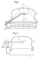
- the sound therapy device for the contactless smashing of concretes in Body of a patient is shown, the sound therapy device has a shock wave source 1 and an ultrasound location system in the form of an imaging scanner 3, which is carried by a bracket 5 which is articulated a fastening 4 is arranged.
- the scanner 3 feels the focus location F of the one emitted by the shock wave source 1 Therapy waves from, because usually at this focus the concrement to be broken is arranged.
- the coupling bellows 2 with at least one lateral lock 9 ( Figure 4) provided the z. B. is opened up by a flexible, stretchable membrane 10 Inserting the scanner 3 into the interior of the coupling bellows 2, such that the bracket 5 of the scanner 2 with an angle the axis of the therapy waves.
- the scanner can also be turned off completely the coupling bellows during the crushing of the concrement be removed to shade the area to be treated To minimize area in the body or in the event of X-ray localization.
- a suitable sound frequency is 7.5 MHz, while for higher depths of penetration, such as B. in gastroenterology or in the renal lithotripsy the 5 MHz or 3.5 MHz scanner are suitable.
- B. in gastroenterology or in the renal lithotripsy the 5 MHz or 3.5 MHz scanner are suitable.
- the scanner is laterally through one of the cutouts in the Coupling bellows inserted into its interior, the bracket either perpendicular to the axis of the therapy waves or can run at an angle to it; in the holder are also advantageously all the necessary cables included for the scanner.
- the scanner itself can either be arranged exactly in the axis of the therapy waves or obliquely in such a way that the focus location F of the therapy waves is contained in the ultrasound image window.
- the scanner can either be installed in the coupling system through complete introduction into the one contained in the coupling bellows Coupling liquid or the scanner can in a preferably thin-walled flexible hose 10 be introduced, which then with the insertion of the scanner even extends into the coupling fluid.
- the scanner with a suitable coupling gel or coupling oil be smeared.
- To different depths of penetration can also support multiple locks, i. H. bushings arranged with membranes or hoses in the coupling bellows become.
- the locks 9 in different positions on the coupling bellows 2 to distribute, so access from different Enable directions. It is particularly advantageous it when the openings are offset by 90 ° to each other are then a simple three-dimensional orientation is possible.
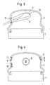
- Figure 2 are schematically with 6 and 7 two position sensors designated and by the double arrow different adjustment options the scanner 3 within the coupling bellows 2, the position sensors 6 and 7 serve to connect an external one Control of the scanner 3 through the holder 5 make.
- Figure 3 shows how an elastic membrane 10 in shape a thin, elongated tube around the scanner 3 extends around after this into the interior of the coupling bellows 2 has been introduced.
- Figure 5 finally shows two different arrangements of the scanner 3, this for minimal shadowing during therapy, as the solid lines show, is located near the introducer and during his Use, as shown in dashed lines, roughly the Axis of the therapy wave.
- a targeted adjustment in one Position outside the axis of the therapy waves is special in renal lithotripsy, a suitable one To seek out sound windows between the ribs.
- To the to change the scanner's lateral angle of view it can either through one of the staggered locks, or else the therapy source is around the axis of the Therapy waves pivoted at an angle of 90 to 110 °.
- the scanner can also move freely to a large extent in which case e.g. a magnetic or position sensor working with ultrasound (FIG. 2) or mechanical adjustment of the scanner holder is also required is for an overlay of the therapy focus mark in the ultrasound image, e.g. B. by means of a video overlay provides.
- the holder for the scanner is included advantageously designed so that the doctor at the Search for the destination as little as possible, but during the therapy can be locked in a simple way.
Description
Die vorliegende Erfindung betrifft ein Schalltherapiegerät
zur berührungslosen Zertrümmerung von Konkrementen im Körper
eines Patienten nach dem Oberbegriff des Anspruchs 1.The present invention relates to a sound therapy device
for contactless crushing of concrements in the body
a patient according to the preamble of
Aus der EP B 301360 ist ein Stoßwellengenerator zum berührungslosen Zertrümmern eines im Körper eines Lebewesen befindlichen Konkrementes mittels Stoßwellen bekannt, wobei er eine Stoßwellenquelle nach dem elektromagnetischen Prinzip aufweist, die einen Spulenträger, eine Flachspule und eine gegenüber der Flachspule isolierte metallische Membran umfaßt. Die Stoßwellenquelle ist über ein Koppelmedium auf das Konkrement ausrichtbar und mit einem Ultraschallkopf einer Ultraschall-Sende- und Empfangseinrichtung zum Senden eines akustischen Signals und zum Empfang von Echosignalen versehen, die durch Wechselwirkung des akustischen Sendesignals im Körper des Lebewesens entstehen zwecks Ortung und Beobachtung des Konkrements.EP B 301360 describes a shock wave generator for non-contact Smash one in the body of a living being Concrete known by shock waves, where he a shock wave source based on the electromagnetic principle has a bobbin, a flat coil and a metallic membrane insulated from the flat coil includes. The shock wave source is based on a coupling medium the stone can be aligned and with an ultrasound head an ultrasound transmitting and receiving device for transmitting an acoustic signal and to receive echo signals provided by interaction of the acoustic transmission signal in the body of the living being for the purpose of location and Observation of the concretion.
Eine exakte Beobachtung bei Verwendung einer elektromagnetischen Stoßwellenquelle des zu zertrümmernden Konkrements ist dabei dann möglich, wenn die Symmetrieachse der Abtastebene mit der Zentralachse der Stoßwellenquelle zusammenfällt. Im Spulenträger, in der Flachspule und in der metallischen Membran ist dabei jeweils eine zentrale Öffnung vorgesehen, in die der Ultraschallkopf der Ultraschall-Sende- und Empfangseinrichtung derart einführbar ist, daß er mit dem Koppelmedium in Berührung steht. Dadurch soll erreicht werden, daß die Ultraschallwellen und die Stoßwellen immer die gleiche Einfallrichtung aufweisen zur Gewährleistung der immer gleichen Zentrierung der beiden Systeme, um so die Steindesintegration kontinuierlich beobachten zu können. Die zentrische Anordnung des Ultraschallkopfes im Stoßwellengenerator soll für eine Symmetrierung der Stoßwellen sorgen. Das auftretende Maximum in der Mitte des Stoßwellengenerators wird reduziert.An exact observation when using an electromagnetic Shock wave source of the concrement to be crushed is possible if the axis of symmetry of the scanning plane coincides with the central axis of the shock wave source. In the coil former, in the flat coil and in the metallic one The membrane is a central opening into which the ultrasound head of the ultrasound transmitter and receiving device can be inserted such that he is in contact with the coupling medium. This is supposed to can be achieved that the ultrasonic waves and the shock waves always have the same direction of incidence to guarantee the same centering of the two systems, to continuously observe the stone disintegration can. The central arrangement of the ultrasound head in Shock wave generator is designed to symmetrize the shock waves to care. The maximum occurring in the middle of the Shock wave generator is reduced.
Die EP A 355175 beschreibt eine Einrichtung zum berührungslosen Zertrümmern von Konkrementen im Körper eines Lebewesens mit einer Stoßwellenquelle zur Erzeugung von in einer Fokuszone zusammenlaufenden Stoßwellen mit einer Ultraschall-Ortungseinrichtung, die einen B-Scan-Applikator aufweist, mittels dessen zumindest die Fokuszone abtastbar ist und mit Mitteln zur akustischen Kopplung der Stoßwellenquelle und des B-Scan-Applikators mit dem Körper des Lebewesens, wobei der B-Scan-Applikator mehrere Ultraschall-Transducer enthält, mittels derer wenigstens quasigleichzeitig eine der Anzahl der Ultraschall-Transducer entsprechende Anzahl von nährungsweise parallel zueinander verlaufenden Schichten abtastbar ist, deren im Bereich der Fokuszone befindliche Abschnitte einander direkt benachbart sind. Damit wird die Möglichkeit geschaffen, Verlagerungen eines zu zertrümmernden Konkrementes quer zur Richtung der Schichten während der Behandlung zu beobachten, da das Konkrement bei Verlassen einer der Schichten in die jeweils direkt benachbarte Schicht eintritt und somit kontinuierlich abgebildet wird; dabei soll erkannt werden, in welcher Richtung sich das Konkrement verlagert, so daß die Lage der Einrichtung und des Körpers des zu behandelnden Lebewesens relativ zueinander korrigiert werden, bis sich das zu zertrümmernde Konkrement wieder in der Fokuszone, d. h. der mittleren B-Scan-Ebene befindet.EP A 355175 describes a device for contactless Smashing concretions in the body of a living being with a shock wave source to generate in a Focus zone converging shock waves with an ultrasound locating device, which has a B-scan applicator, by means of which at least the focus zone can be scanned and with means for acoustically coupling the shock wave source and the B-scan applicator with the body of the living being, the B-scan applicator being multiple ultrasound transducers contains, by means of which at least quasi-simultaneously one of the number of ultrasonic transducers corresponding number of approximations parallel to each other extending layers is scanned, in the area of Sections located in the focus zone are directly adjacent to one another are. This creates the possibility of relocations a concrement to be crushed transverse to the direction of the Watch layers during treatment because of the concretion when leaving one of the layers in each immediately adjacent layer occurs and thus continuously is mapped; it should be recognized in which Direction the concrement shifts so that the location of the Establishment and body of the living being to be treated be corrected relative to each other until the one to be shattered Concrement back in the focus zone, i.e. H. the middle B-scan level.
Diese bekannten Einrichtungen mit den bildgebenden Ultraschall-Scannern liefern also ein Real-Time-Bild des Behandlungsverlauf ohne zusätzliche Strahlenbelastung des Patienten und liefern damit dem Arzt eine einfache Orientierung. Jedoch sind die bekannten Einrichtungen noch mit dem Nachteil behaftet, daß die Scanner in die Stoßquelle mit eingebaut werden müssen (sogenannte Inline-Scanner), wobei dieser Einbau sehr aufwendig und kostenintensiv ist und eine speziell daran angepasste Modifikation der Schallquellen erfordert, die zu Energieverlusten bei der Therapie führen.These known devices with the imaging ultrasound scanners deliver a real-time picture of the course of treatment without additional radiation exposure to the patient and thus provide the doctor with a simple orientation. However, the known devices still have the disadvantage afflicted that the scanner built into the shock source must be (so-called inline scanner), this Installation is very complex and costly and one specially modified modification of the sound sources requires that lead to energy loss during therapy.
Aufgabe der vorliegenden Erfindung ist es, ein besonders einfaches Schalltherapiegerät zu schaffen, welches eine exakte Beobachtung und/oder Lokalisation des Konkrements mit einer beliebigen handelsüblichen Stoßwellenquelle ermöglicht.The object of the present invention is a particular to create a simple sound therapy device that is accurate Observation and / or localization of the calculus with any commercially available shock wave source.
Ausgehend von einem Schalltherapiegerät der eingangs näher
genannten Art erfolgt die Lösung dieser Aufgabe mit dem im
kennzeichnenden Teil des Anspruchs 1 angegebenen Merkmalen;
vorteilhafte Ausgestaltungen sind in den Unteransprüchen
beschrieben.Starting from a sound therapy device closer to the beginning
mentioned type the solution to this problem takes place with the im
characterizing part of
Die Erfindung bietet den Vorteil, daß durch das seitlichen Einführen des Scanners in den Koppelbalg (oder durch die Struktur der Stoßwellenquelle hindurch) eine optimale Adaption der Scanner-Parameter gewährleistet wird, daß der Scanner für die Ortung auf einfachste Art und Weise in seine jeweilige Position innerhalb des Koppelbalges gebracht werden kann, und daß bei Bedarf der Scanner aus dem Weg der Therapiewellen entfernt werden kann, um jegliche Abschattung des zu therapierenden Konkrementes zu vermeiden, bzw. um eine ungestörte Röntgenortung vornehmen zu können.The invention has the advantage that the lateral Introduce the scanner into the coupling bellows (or through the Structure of the shock wave source) an optimal adaptation the scanner parameter ensures that the The easiest way to locate your scanner brought respective position within the coupling bellows can be, and that if necessary the scanner out of the way of Therapy waves can be removed to remove any shade to avoid the concrement to be treated, or to be able to carry out an undisturbed X-ray location.
Zu diesem Zweck wird der Scanner (oder auch mehrere Scanner) durch die seitliche im Koppelbalg angeordneten Schleusen eingeführt, wobei die Halterung des eigentlichen Scanners entweder rechtwinklig zur Achse der Therapiewellen oder in einem Winkel dazu verlaufen kann. Diese Halterung nimmt auch die notwendigen Kabel für den Scanner auf.For this purpose the scanner (or several scanners) through the side locks arranged in the coupling bellows introduced, the bracket of the actual scanner either perpendicular to the axis of the therapy waves or can run at an angle to it. This bracket also takes the necessary cables for the scanner.
Dabei ist es möglich, den Scanner entweder genau in die Achse der Therapiewellen einzuführen oder schräg dazu derart anzuordnen, daß der Fokusort der Therapiewellen in dem durch den Scanner erzeugten Ultraschallbild enthalten ist. Es ist ferner auch möglich, den Scanner oder die Scanner in den Koppelbalg entweder durch vollständiges Einbringen in die Koppelflüssigkeit anzuordnen oder aber den Scanner in einem vorzugsweise dünnwandigen, flexiblen, langgestreckten, dehnbaren Schlauch einzuführen, der sich in die Koppelflüssigkeit erstreckt. Zur besseren Kopplung zwischen Scanner und Koppelmedium kann der Scanner mit einem geeigneten Koppelgel oder einem Koppelöl bestrichen werden.It is possible to either place the scanner exactly in the Introduce axis of the therapy waves or obliquely to it to arrange that the focus of the therapy waves in the ultrasound image generated by the scanner is included. It is also possible to put the scanner or scanners in the coupling bellows either by fully inserting it into to arrange the coupling liquid or in the scanner a preferably thin-walled, flexible, elongated, insert a stretchable hose into the coupling fluid extends. For better coupling between The scanner and coupling medium can be scanned with a suitable scanner Coupling gel or a coupling oil can be coated.
Um verschiedene Einbringtiefen zu unterstützen, können auch mehrere geeignete Durchführungen oder Schläuche im Koppelbalg angebracht werden.To support different insertion depths, too several suitable bushings or hoses in the coupling bellows be attached.
Weiterhin ist es möglich, die Einlaßöffnungen, d. h. die Schleusen, in verschiedenen Positionen auf dem Koppelbalg zu verteilen, um so einen Zugang aus mehreren Richtungen zu erlauben. Besonders vorteilhaft ist es, wenn die Öffnungen jeweils um 90° zueinander versetzt sind, um dergestalt eine dreidimensionale Orientierung und Beobachtung des Konkrementes zu ermöglichen.Furthermore, it is possible to adjust the inlet openings, i.e. H. the Locks, in different positions on the coupling bellows to distribute so access from multiple directions allow. It is particularly advantageous if the openings are each offset by 90 ° to one another in such a way three-dimensional orientation and observation of the calculus to enable.
Im einfachsten Fall wird der Scanner mittels einer geeigneten Halterung an einem festen Ort eingebaut. Dabei kann er so justiert werden, daß die Bildachse genau mit der Achse der Therapiewellen übereinstimmt, so daß eine eindeutige Orientierung auch ohne die Einblendung der herkömmlichen Fadenkreuze ermöglicht wird, wenn, wie heutzutage üblich, im Ultraschallbild Entfernungsmarken eingeblendet werden und eine einblendbare Mittelachse zur Verfügung steht.In the simplest case, the scanner is used with a suitable one Bracket installed in a fixed place. He can be adjusted so that the image axis exactly with the axis the therapy waves coincide, so that a clear Orientation even without showing the conventional Crosshairs is enabled if, as is common today, distance marks are shown in the ultrasound image and a fade-in central axis is available.
Bei einer weiteren Ausführungsform kann der Scanner mittels einer beweglichen Halterung derart bewegt werden, daß er bei der eigentlichen Therapie seitlich aus der Achse der Therapiewellen herausgeschwenkt wird und somit die Therapiewellen nur minimal abschattet, während er zum Orten und/oder Beobachten in eine axiale Position gebracht wird. Eine gezielte Verstellung außerhalb der Achse der Therapiewellen ist auch dann möglich, wenn z. B. bei der Nierenlithotripsie ein geeignetes Schallfenster zwischen den Rippen aufzusuchen ist.In a further embodiment, the scanner can by means of a movable bracket to be moved so that it in the actual therapy from the side of the axis Therapy waves are swung out and thus the therapy waves shadows only minimally while locating and / or observation is brought into an axial position. A targeted adjustment outside the axis of the therapy waves is also possible if e.g. B. in renal lithotripsy a suitable sound window between the ribs is to be visited.
Um den lateralen Blickwinkel des Scanners zu ändern, kann er entweder durch eines der versetzten Fenster eingebracht werden oder aber die Stoßwellenquelle kann um ihre Achse um einen Winkel, z. B. zwischen 90° und 110° verschwenkt werden. Eine weitere Möglichkeit zur genauen Positionsbestimmung des Scanners besteht in der Verwendung von Positionsaufnehmern an seiner Halterung, um dann im Ultraschallbild positionsrichtung eine Marke, z. B. ein Fadenkreuz zur Markierung der Fokusposition der Therapiewellen einzublenden. Gegebenenfalls kann auch der Scanner weitgehend frei beweglich sein, wobei in diesem Fall entweder ein magnetischer oder ein mit Ultraschall arbeitender Positionssensor an geeigneter Stelle der Scanner-Halterung angebracht wird, welcher für eine Einblendung einer Marke in den Therapiefokus im Ultraschallbild sorgt, z. B. mittels eines Video-Overlays. Dabei wird die Scanner-Halterung vorteilhafterweise derart ausgelegt, daß sie den Arzt bei der Suche des Zielortes möglichst wenig behindert, jedoch während der Therapie auf einfache Art und Weise arretiert werden kann.To change the lateral viewing angle of the scanner, you can either brought in through one of the staggered windows or the shock wave source can around its axis an angle, e.g. B. pivoted between 90 ° and 110 °. Another possibility for exact position determination of the scanner consists in the use of position sensors on its holder, to then position in the ultrasound image a brand, e.g. B. a crosshair for marking show the focus position of the therapy waves. Possibly the scanner can largely move freely be, in which case either a magnetic or an ultrasonic position sensor at a suitable one Place the scanner holder is attached, which for the insertion of a brand into the therapy focus provides in the ultrasound image, e.g. B. by means of a video overlay. The scanner holder is advantageously interpreted in such a way that it helps the doctor in the search for the Destination as little as possible, but during the Therapy can be locked in a simple manner.
Schließlich ist es möglich, durch geeignete motorische Schwenkung des Scanners um seine Achse eine dreidimensionale Darstellung des den Fokus einschließenden Volumens zu erzeugen, wodurch auch die Darstellung von senkrechten oder schrägen Schnitten ohne Veränderung der Scannerposition möglich ist.Finally, it is possible through suitable motor Swiveling the scanner around its axis a three-dimensional Representation of the volume enclosing the focus generate, which also the display of vertical or oblique cuts without changing the scanner position is possible.
Im folgenden wird die Erfindung anhand der Zeichnung näher
erläutert, in der vorteilhafte Ausführungsbeispiele dargestellt
sind. Es zeigen:
In den Figuren, in denen gleiche Teile mit gleichen Bezugszeichen
versehen sind, ist schematisch ein Schalltherapiegerät
zur berührungslosen Zertrümmerung von Konkremten im
Körper eines Patienten dargestellt, wobei das Schalltherapiegerät
eine Stoßwellenquelle 1 aufweist sowie ein Ultraschall-Ortungssystem
in Form eines bildgebenden Scanners 3,
der von einer Halterung 5 getragen wird, die gelenkig an
einer Befestigung 4 angeordnet ist. Der Scanner 3 tastet
den Fokusort F der von der Stoßwellenquelle 1 ausgesandten
Therapiewellen ab, weil üblicherweise an diesem Fokusort
das zu zertrümmernde Konkrement angeordnet ist.In the figures, in which the same parts have the same reference numerals
are provided, is schematically a sound therapy device
for the contactless smashing of concretes in
Body of a patient is shown, the sound therapy device
has a
Mit 2 ist ein üblicher Koppelbalg bezeichnet, in dem eine geeignete Koppelflüssigkeit zur Einleitung der Therapiewellen in den Körper des Patienten angeordnet ist.2 with a conventional coupling bellows is designated, in which one suitable coupling fluid to initiate the therapy waves is placed in the patient's body.
Erfindungsgemäß ist nun der Koppelbalg 2 mit mindestens einer
seitlichen Schleuse 9 (Figur 4) versehen, die z. B.
durch eine flexible dehnbare Membran 10 erschlossen ist zum
Einführen des Scanners 3 in das Innere des Koppelbalgs 2,
derart, daß die Halterung 5 des Scanners 2 einen Winkel mit
der Achse der Therapiewellen einschließt. According to the invention, the
Durch die seitliche Einführung des Scanners samt seiner Halterung durch eine der Öffnungen des Koppelbalgs hindurch entfällt jeglicher Eingriff in die Stoßwellenquelle selbst. Zusätzlich erzielt man noch den Vorteil des einfachen Auswechseln des Scanners zur optimalen Anpassung des Scannerparameter an die Therapie sowie des einfachen Einschubes des Scanners für die Behandlung bzw. Ortung bzw. Beobachtung durch geeignete Auswahl einer der Öffnungen des Koppelbalges. Bei Bedarf kann auch der Scanner vollständig aus dem Koppelbalg während der Zertrümmerung des Konkrementes entfernt werden, um eine Abschattung des zu therapierenden Gebietes im Körper zu minimieren oder auch für den Fall der Röntgenortung.Through the lateral insertion of the scanner and its Holder through one of the openings of the coupling bellows there is no intervention in the shock wave source itself. You also get the advantage of easy replacement of the scanner for optimal adjustment of the scanner parameters the therapy and the simple insertion of the scanner for treatment, location or observation through suitable selection of one of the openings of the coupling bellows. If necessary, the scanner can also be turned off completely the coupling bellows during the crushing of the concrement be removed to shade the area to be treated To minimize area in the body or in the event of X-ray localization.
Als Scanner eignet sich z. B. ein Rektal- oder Gynäkologischer Scanner, wobei für oberflächennahe Ortungsaufgaben eine geeignete Schallfrequenz bei 7,5 MHz liegt, während für höhere Eindringtiefen, wie z. B. in der Gastroenterologie oder in der Nierenlithotripsie die 5 MHz bzw. 3,5 MHz-Scanner geeignet sind. Um eine räumliche Übersicht zu erhalten, können auch sogenannte "Biplane-Scanner" oder dreidimensionale Anordnungen eingesetzt werden.As a scanner z. B. a rectal or gynecological Scanner, being used for near-surface location tasks a suitable sound frequency is 7.5 MHz, while for higher depths of penetration, such as B. in gastroenterology or in the renal lithotripsy the 5 MHz or 3.5 MHz scanner are suitable. To get a spatial overview, can also be called "biplane scanners" or three-dimensional Arrangements are used.
Wie die Figuren und insbesondere Figur 4 erkennen lassen, wird der Scanner seitlich durch eine der Aussparungen im Koppelbalg in dessen Inneres eingeführt, wobei die Halterung entweder rechtwinklig zur Achse der Therapiewellen oder unter einem Winkel dazu verlaufen kann; in der Halterung sind auch vorteilhafterweise alle notwendigen Kabel für den Scanner enthalten. Der Scanner selbst kann entweder genau in der Achse der Therapiewellen angeordnet werden oder schräg dazu dergestalt, daß der Fokusort F der Therapiewellen im Ultraschallbildfenster enthalten ist.As can be seen from the figures and in particular from FIG. 4, the scanner is laterally through one of the cutouts in the Coupling bellows inserted into its interior, the bracket either perpendicular to the axis of the therapy waves or can run at an angle to it; in the holder are also advantageously all the necessary cables included for the scanner. The scanner itself can either be arranged exactly in the axis of the therapy waves or obliquely in such a way that the focus location F of the therapy waves is contained in the ultrasound image window.
Der Einbau des Scanners in das Koppelsystem kann entweder
durch vollständiges Einbringen in die im Koppelbalg enthaltende
Koppelflüssigkeit erfolgen oder aber der Scanner kann
in einem vorzugsweise dünnwandigen flexiblen Schlauch 10
eingeführt werden, der sich dann mit dem Einschub des Scanners
selbst bis in die Koppelflüssigkeit erstreckt. Zur
besseren Kopplung zwischen Scanner und Koppelmedium kann
der Scanner dabei mit einem geeigneten Koppelgel oder Koppelöl
bestrichen werden. Um verschiedene Eindringtiefen zu
unterstützen, können auch mehrere Schleusen, d. h. Durchführungen
mit Membranen oder Schläuche im Koppelbalg angeordnet
werden.The scanner can either be installed in the coupling system
through complete introduction into the one contained in the coupling bellows
Coupling liquid or the scanner can
in a preferably thin-walled
Weiterhin ist es möglich, wie insbesondere Figur 4 zeigt,
die Schleusen 9 in verschiedenen Positionen auf dem Koppelbalg
2 zu verteilen, um so einen Zugang aus unterschiedlichen
Richtungen zu ermöglichen. Besonders vorteilhaft ist
es, wenn die Öffnungen um jeweils 90° zueinander versetzt
sind, da dann eine einfache dreidimensionale Orientierung
möglich ist.It is also possible, as shown in particular in FIG. 4,
the
In Figur 2 sind schematisch mit 6 und 7 zwei Positionsgeber
bezeichnet und durch den Doppelpfeil verschiedene Verstellmöglichkeiten
des Scanners 3 innerhalb des Koppelbalges 2,
wobei die Positionsgeber 6 und 7 dazu dienen, eine externe
Ansteuerung des Scanners 3 durch die Halterung 5 hindurch
vorzunehmen. In Figure 2 are schematically with 6 and 7 two position sensors
designated and by the double arrow different adjustment options
the
Figur 3 zeigt wie sich eine elastische Membran 10 in Form
eines dünnen, langgestreckten Schlauches um den Scanner 3
herum erstreckt, nachdem dieser in das Innere des Koppelbalges
2 eingeführt worden ist.Figure 3 shows how an
Figur 5 zeigt schließlich zwei unterschiedliche Anordnungen
des Scanners 3, wobei dieser zur minimalen Abschattung während
der Therapie sich, wie die ausgezogenen Linien zeigen,
in der Nähe der Einführschleuse befindet und während seines
Einsatzes, wie es gestrichelt dargestellt ist, in etwa der
Achse der Therapiewelle. Eine gezielte Verstellung in eine
Position außerhalb der Achse der Therapiewellen ist insbesondere
bei der Nierenlithotripsie günstig, um ein geeignetes
Schallfenster zwischen den Rippen aufzusuchen. Um den
lateralen Blickwinkel des Scanners zu ändern, kann er entweder
durch eine der versetzten Schleusen eingebracht werden,
oder aber die Therapiequelle wird um die Achse der
Therapiewellen in einem Winkel von 90 bis 110° verschwenkt.Figure 5 finally shows two different arrangements
of the
Gegebenenfalls kann der Scanner auch weitgehend frei beweglich sein, wobei in diesem Fall z.B. ein magnetischer oder mit Ultraschall arbeitender Positionssensor (Figur 2) oder auch eine mechanische Verstellung der Scanner-Halterung erforderlich ist, die für eine Einblendung der Therapiefokusmarke im Ultraschallbild, z. B. mittels eines Video-Overlays sorgt. Die Halterung für den Scanner wird dabei vorteilhafterweise so ausgelegt, daß sie den Arzt bei der Suche des Zielorts möglichst wenig behindert, jedoch während der Therapie auf einfache Art arretiert werden kann.If necessary, the scanner can also move freely to a large extent in which case e.g. a magnetic or position sensor working with ultrasound (FIG. 2) or mechanical adjustment of the scanner holder is also required is for an overlay of the therapy focus mark in the ultrasound image, e.g. B. by means of a video overlay provides. The holder for the scanner is included advantageously designed so that the doctor at the Search for the destination as little as possible, but during the therapy can be locked in a simple way.
Claims (16)
- Sonic therapy device for contactless disintegration of concrements in a body of a patient, with a shock-wave source, with an ultrasonic positioning system in the form of an imaging scanner, which scans the focal position of the therapy wave emitted by the shock-wave source, and with a coupling bellow between the shock-wave source and the body surface of the patient, characterised in that the coupling bellow (2) or a structure of the shock-wave source is provided with at least one lateral port (9), which is closed by a flexible extensible diaphragm (10), for inserting the scanner (3) into the interior of the coupling bellow in such a way that the support (5) of the scanner (3) makes an angle with the axis (11) of the therapy waves.
- Sonic therapy device according to Claim 1, characterised in that, during its use, the scanner is arranged in the coupling bellow in such a way that the therapy focal position F is contained in the image which it generates.
- Sonic therapy device according to one of the preceding claims, characterised in that the port is closed by a diaphragm in the form of cuspid valves.
- Sonic therapy device according to one of the preceding claims, characterised in that the scanner is firmly connected to a support in such a way that, after alignment with the therapy focus, it uniquely identifies the therapy focal position via marks superimposed on the ultrasonic image.
- Sonic therapy device according to one of the preceding claims, characterised in that the scanner is arranged movably on a support (4) in such a way that unique assignment of the therapy focus (F) to the ultrasonic image is made possible.
- Sonic therapy device according to one of the preceding claims, characterised in that the scanner is movable in the coupling bellow in such a way that it can be brought into different positions for positioning and for therapy, and held there.
- Sonic therapy device according to one of the preceding claims, characterised in that the scanner is provided with a sensor system for determining its position relative to the therapy focus, so that the scanner is freely movable without losing the fix of the focus.
- Sonic therapy device according to one of the preceding claims, characterised in that the therapy source can be rotated and/or tilted about the shock-wave axis.
- Sonic therapy device according to one of the preceding claims, characterised in that the scanner has a plurality of crystals or crystal arrays, or contains a plurality of mechanical movement axes, in order to simultaneously or successively record images of a plurality of planes or three-dimensional images.
- Sonic therapy device according to one of the preceding claims, characterised in that the scanner is protected against the effect of the therapy waves by mechanical protection at its rear side facing away from the focal position (F).
- Sonic therapy device according to Claim 10, characterised in that the protection of the scanner consists of a combination of closed-pore foam and a metal or plastic plate.
- Sonic therapy device according to one of the preceding claims, characterised in that a mechanical scanner is involved.
- Sonic therapy device according to one of the preceding claims, characterised in that the scanner is a linear scanner or a curved-array scanner.
- Sonic therapy device according to one of the preceding claims, characterised in that the scanner fixture contains at least one position encoder (6, 7), which can be externally driven and which makes it possible to construct a three-dimensional ultrasonic image by means of external image processing.
- Sonic therapy device according to one of the preceding claims, characterised in that the scanner has an essentially tubular housing, in that the scan plane is substantially perpendicular to the housing axis, and in that the tubular housing can be brought substantially radially into the therapy waves.
- Sonic therapy device according to one of the preceding claims, characterised in that the image-generating ultrasonic transducer of the scanner is arranged at the end of the tubular housing.
Applications Claiming Priority (2)
| Application Number | Priority Date | Filing Date | Title |
|---|---|---|---|
| DE19641935 | 1996-10-11 | ||
| DE19641935A DE19641935C1 (en) | 1996-10-11 | 1996-10-11 | Sound therapy device for contactless dispersion of aggregation in bodies of patients |
Publications (3)
| Publication Number | Publication Date |
|---|---|
| EP0835643A2 EP0835643A2 (en) | 1998-04-15 |
| EP0835643A3 EP0835643A3 (en) | 1998-07-01 |
| EP0835643B1 true EP0835643B1 (en) | 2003-08-27 |
Family
ID=7808454
Family Applications (1)
| Application Number | Title | Priority Date | Filing Date |
|---|---|---|---|
| EP97117456A Expired - Lifetime EP0835643B1 (en) | 1996-10-11 | 1997-10-09 | Sonic therapy |
Country Status (3)
| Country | Link |
|---|---|
| EP (1) | EP0835643B1 (en) |
| DE (2) | DE19641935C1 (en) |
| ES (1) | ES2205109T3 (en) |
Families Citing this family (3)
| Publication number | Priority date | Publication date | Assignee | Title |
|---|---|---|---|---|
| DE10163019A1 (en) * | 2001-12-20 | 2003-07-10 | Dornier Medtech Holding Int Gmbh | Ultrasound Scanner |
| JP6772288B2 (en) * | 2016-03-11 | 2020-10-21 | ソルボンヌ・ユニヴェルシテSorbonne Universite | An extracorporeal ultrasound generation therapy device for the treatment of the spinal cord and spinal nerves, a device equipped with the device, and a method using the device. |
| JP6783319B2 (en) | 2016-03-11 | 2020-11-11 | ソルボンヌ・ユニヴェルシテSorbonne Universite | Implantable ultrasound generation therapy devices for the treatment of the spinal cord and / or spinal nerves, devices and methods comprising the devices. |
Family Cites Families (9)
| Publication number | Priority date | Publication date | Assignee | Title |
|---|---|---|---|---|
| DE3503702C2 (en) * | 1985-02-04 | 1993-10-28 | Siemens Ag | Coupling device for acoustic waves |
| US4763652A (en) * | 1986-04-16 | 1988-08-16 | Northgate Research, Inc. | Aiming system for kidney stone disintegrator |
| DE3724562C1 (en) | 1987-07-24 | 1989-01-12 | Spectrospin Ag | Cryostat and assembly method |
| US4928672A (en) * | 1987-07-31 | 1990-05-29 | Siemens Aktiengesellschaft | Shockwave source having a centrally disposed ultrasound locating system |
| EP0355175A1 (en) * | 1988-08-17 | 1990-02-28 | Siemens Aktiengesellschaft | Apparatus for the contactless disintegration of concrements in the body of a living being |
| US5078144A (en) * | 1988-08-19 | 1992-01-07 | Olympus Optical Co. Ltd. | System for applying ultrasonic waves and a treatment instrument to a body part |
| DE4007669C3 (en) * | 1990-03-10 | 1997-11-13 | Wolf Gmbh Richard | Shock wave treatment device |
| US5329928A (en) * | 1993-08-16 | 1994-07-19 | Bantum Tripter Joint Venture | Reflected shockwave shielding device |
| DE19543344C1 (en) * | 1995-11-22 | 1996-12-12 | Dornier Medizintechnik | Device for shock wave therapy for treating patients near the surface of the body, e.g. for tennis elbow |
-
1996
- 1996-10-11 DE DE19641935A patent/DE19641935C1/en not_active Expired - Fee Related
-
1997
- 1997-10-09 EP EP97117456A patent/EP0835643B1/en not_active Expired - Lifetime
- 1997-10-09 DE DE59710651T patent/DE59710651D1/en not_active Expired - Lifetime
- 1997-10-09 ES ES97117456T patent/ES2205109T3/en not_active Expired - Lifetime
Also Published As
| Publication number | Publication date |
|---|---|
| DE19641935C1 (en) | 1997-09-11 |
| DE59710651D1 (en) | 2003-10-02 |
| EP0835643A2 (en) | 1998-04-15 |
| ES2205109T3 (en) | 2004-05-01 |
| EP0835643A3 (en) | 1998-07-01 |
Similar Documents
| Publication | Publication Date | Title |
|---|---|---|
| DE3826709C2 (en) | Ultrasound therapy device | |
| DE4143540C2 (en) | Therapeutic assembly for treatment by acoustic irradiation | |
| EP0397980B1 (en) | Lithotriptor | |
| EP0301360B1 (en) | Shock wave apparatus with a central ultrasonic location system | |
| DE4241161C2 (en) | Acoustic therapy facility | |
| EP1749488B1 (en) | Shockwave therapy apparatus with imaging | |
| DE3743883C2 (en) | Medical ultrasound treatment device | |
| DE3009482A1 (en) | DIAGNOSTIC DEVICE FOR AN ENDOSCOPE | |
| DE3328068A1 (en) | DEVICE FOR CONTACTLESS CRUSHING OF CONCRETE | |
| DE4318237A1 (en) | Device for the treatment of biological tissue and body concretions | |
| DE3617032C2 (en) | Lithotripsy device with extracorporeal shock wave generator | |
| DE19548000C1 (en) | Device for locating calculus in a patient's body | |
| DE3328039C2 (en) | FACILITIES FOR THE CONTACTLESS SMASHING OF A CONCERMENT IN THE BODY OF A LIVING BEING | |
| DE3817726A1 (en) | DEVICE FOR SPACIOUS ULTRASONIC LOCATION OF CONCRETE | |
| EP0265742A1 (en) | Lithotripter with a locating device | |
| DE3932364C2 (en) | ||
| DE19622919C1 (en) | Device for location and destruction of calculi in body of patient | |
| EP0328943B1 (en) | Shock wave generator for the non-contacting disintegration of concretions | |
| EP0835643B1 (en) | Sonic therapy | |
| DE4135177C2 (en) | Therapy device for the treatment of a living being with focused acoustic waves | |
| EP0365981B1 (en) | Lithotripsy apparatus | |
| DE102011017343B3 (en) | Medical therapy device for intracorporeal treatment, has video module for imaging acquisition of treatment field, where video module is arranged in capsule endoscope, and detecting unit of endoscope detects position of treatment field | |
| DE3703333A1 (en) | Lithotripter with ultrasonic transducer, arranged in front of the focusing device, for sector scanning | |
| DE20315924U1 (en) | Lithotripsy lens and ultrasonic diagnostic lens incorporates ultrasonic emitter in rotating housing | |
| DE8322427U1 (en) | Device for the contactless smashing of concrements |
Legal Events
| Date | Code | Title | Description |
|---|---|---|---|
| PUAI | Public reference made under article 153(3) epc to a published international application that has entered the european phase |
Free format text: ORIGINAL CODE: 0009012 |
|
| AK | Designated contracting states |
Kind code of ref document: A2 Designated state(s): CH DE ES FR GB LI NL |
|
| PUAL | Search report despatched |
Free format text: ORIGINAL CODE: 0009013 |
|
| AK | Designated contracting states |
Kind code of ref document: A3 Designated state(s): AT BE CH DE DK ES FI FR GB GR IE IT LI LU MC NL PT SE |
|
| AKX | Designation fees paid |
Free format text: CH DE ES FR GB LI NL |
|
| RBV | Designated contracting states (corrected) |
Designated state(s): CH DE ES FR GB LI NL |
|
| 17P | Request for examination filed |
Effective date: 19990309 |
|
| RAP1 | Party data changed (applicant data changed or rights of an application transferred) |
Owner name: DORNIER MEDTECH HOLDING INTERNATIONAL GMBH |
|
| RAP1 | Party data changed (applicant data changed or rights of an application transferred) |
Owner name: DORNIER MEDIZINTECHNIK GMBH |
|
| GRAH | Despatch of communication of intention to grant a patent |
Free format text: ORIGINAL CODE: EPIDOS IGRA |
|
| RAP1 | Party data changed (applicant data changed or rights of an application transferred) |
Owner name: DORNIER MEDIZINTECHNIK GMBH |
|
| RAP1 | Party data changed (applicant data changed or rights of an application transferred) |
Owner name: DORNIER MEDTECH SYSTEMS GMBH |
|
| GRAS | Grant fee paid |
Free format text: ORIGINAL CODE: EPIDOSNIGR3 |
|
| GRAA | (expected) grant |
Free format text: ORIGINAL CODE: 0009210 |
|
| AK | Designated contracting states |
Designated state(s): CH DE ES FR GB LI NL |
|
| REG | Reference to a national code |
Ref country code: GB Ref legal event code: FG4D Free format text: NOT ENGLISH |
|
| REG | Reference to a national code |
Ref country code: CH Ref legal event code: EP |
|
| GBT | Gb: translation of ep patent filed (gb section 77(6)(a)/1977) | ||
| REF | Corresponds to: |
Ref document number: 59710651 Country of ref document: DE Date of ref document: 20031002 Kind code of ref document: P |
|
| REG | Reference to a national code |
Ref country code: CH Ref legal event code: NV Representative=s name: AVV. FRANCO PAGANI |
|
| REG | Reference to a national code |
Ref country code: ES Ref legal event code: FG2A Ref document number: 2205109 Country of ref document: ES Kind code of ref document: T3 |
|
| ET | Fr: translation filed | ||
| PLBE | No opposition filed within time limit |
Free format text: ORIGINAL CODE: 0009261 |
|
| STAA | Information on the status of an ep patent application or granted ep patent |
Free format text: STATUS: NO OPPOSITION FILED WITHIN TIME LIMIT |
|
| 26N | No opposition filed |
Effective date: 20040528 |
|
| PGFP | Annual fee paid to national office [announced via postgrant information from national office to epo] |
Ref country code: DE Payment date: 20101130 Year of fee payment: 14 |
|
| REG | Reference to a national code |
Ref country code: CH Ref legal event code: PFA Owner name: DORNIER MEDTECH SYSTEMS GMBH Free format text: DORNIER MEDTECH SYSTEMS GMBH#ARGELSRIEDER FELD 7#82234 WESSLING (DE) -TRANSFER TO- DORNIER MEDTECH SYSTEMS GMBH#ARGELSRIEDER FELD 7#82234 WESSLING (DE) |
|
| PGFP | Annual fee paid to national office [announced via postgrant information from national office to epo] |
Ref country code: GB Payment date: 20101025 Year of fee payment: 14 |
|
| PGFP | Annual fee paid to national office [announced via postgrant information from national office to epo] |
Ref country code: CH Payment date: 20111020 Year of fee payment: 15 Ref country code: NL Payment date: 20111024 Year of fee payment: 15 Ref country code: FR Payment date: 20111026 Year of fee payment: 15 Ref country code: ES Payment date: 20111011 Year of fee payment: 15 |
|
| REG | Reference to a national code |
Ref country code: NL Ref legal event code: V1 Effective date: 20130501 |
|
| REG | Reference to a national code |
Ref country code: CH Ref legal event code: PL |
|
| GBPC | Gb: european patent ceased through non-payment of renewal fee |
Effective date: 20121009 |
|
| REG | Reference to a national code |
Ref country code: FR Ref legal event code: ST Effective date: 20130628 |
|
| PG25 | Lapsed in a contracting state [announced via postgrant information from national office to epo] |
Ref country code: CH Free format text: LAPSE BECAUSE OF NON-PAYMENT OF DUE FEES Effective date: 20121031 Ref country code: LI Free format text: LAPSE BECAUSE OF NON-PAYMENT OF DUE FEES Effective date: 20121031 Ref country code: DE Free format text: LAPSE BECAUSE OF NON-PAYMENT OF DUE FEES Effective date: 20130501 Ref country code: GB Free format text: LAPSE BECAUSE OF NON-PAYMENT OF DUE FEES Effective date: 20121009 |
|
| REG | Reference to a national code |
Ref country code: DE Ref legal event code: R119 Ref document number: 59710651 Country of ref document: DE Effective date: 20130501 |
|
| PG25 | Lapsed in a contracting state [announced via postgrant information from national office to epo] |
Ref country code: NL Free format text: LAPSE BECAUSE OF NON-PAYMENT OF DUE FEES Effective date: 20130501 Ref country code: FR Free format text: LAPSE BECAUSE OF NON-PAYMENT OF DUE FEES Effective date: 20121031 |
|
| REG | Reference to a national code |
Ref country code: ES Ref legal event code: FD2A Effective date: 20140116 |
|
| PG25 | Lapsed in a contracting state [announced via postgrant information from national office to epo] |
Ref country code: ES Free format text: LAPSE BECAUSE OF NON-PAYMENT OF DUE FEES Effective date: 20121010 |