EP0835559B1 - Non-linearity estimation method and device - Google Patents
Non-linearity estimation method and device Download PDFInfo
- Publication number
- EP0835559B1 EP0835559B1 EP96938272A EP96938272A EP0835559B1 EP 0835559 B1 EP0835559 B1 EP 0835559B1 EP 96938272 A EP96938272 A EP 96938272A EP 96938272 A EP96938272 A EP 96938272A EP 0835559 B1 EP0835559 B1 EP 0835559B1
- Authority
- EP
- European Patent Office
- Prior art keywords
- signal
- measured
- frequency
- intermodulation
- synchronous detection
- Prior art date
- Legal status (The legal status is an assumption and is not a legal conclusion. Google has not performed a legal analysis and makes no representation as to the accuracy of the status listed.)
- Expired - Lifetime
Links
Images


Classifications
-
- H—ELECTRICITY
- H04—ELECTRIC COMMUNICATION TECHNIQUE
- H04B—TRANSMISSION
- H04B10/00—Transmission systems employing electromagnetic waves other than radio-waves, e.g. infrared, visible or ultraviolet light, or employing corpuscular radiation, e.g. quantum communication
- H04B10/50—Transmitters
- H04B10/58—Compensation for non-linear transmitter output
-
- H—ELECTRICITY
- H04—ELECTRIC COMMUNICATION TECHNIQUE
- H04B—TRANSMISSION
- H04B10/00—Transmission systems employing electromagnetic waves other than radio-waves, e.g. infrared, visible or ultraviolet light, or employing corpuscular radiation, e.g. quantum communication
- H04B10/50—Transmitters
- H04B10/501—Structural aspects
- H04B10/503—Laser transmitters
-
- H—ELECTRICITY
- H04—ELECTRIC COMMUNICATION TECHNIQUE
- H04B—TRANSMISSION
- H04B2210/00—Indexing scheme relating to optical transmission systems
- H04B2210/07—Monitoring an optical transmission system using a supervisory signal
- H04B2210/075—Monitoring an optical transmission system using a supervisory signal using a pilot tone
Definitions
- the invention relates to non-linear circuits and more particularly the linearity correction devices of such circuits.
- Signal transmission systems are generally sensitive to the non-linearity of the various elements which constitute them. If the non-linearity of these elements is imposed by physics, it remains despite everything possible to add linearization devices to improve the overall system performance. In this case we must have a means for measuring the residual non-linearities of the system to be corrected for be able to optimize the parameters of the linearization device. If more the non-linearities of the system are called to evolve over time, the measuring device must be integrated into the system to react in real time on linearization devices.
- a known means of estimating non-linearity consists of the use of one or more pilot signals.
- Figure 1 shows such a device according to the prior art.
- the pilot signal most often sinusoidal, is generated by a oscillator or pilot generator 1. This signal is sent on a second input of an adder 2, the first input of which is supplied by the signal to be transmitted or useful signal.
- the non-linear device of which seeks to correct the annoying effects due to non-linearity is connected in downstream of the pilot frequency generator, for example at the output of the adder 2.
- a coupler 4 is connected at the output of the non-linear device to take, on its coupled output, the intermodulations created by this last. The direct output of the coupler provides the signal to be exploited, which will be possibly filtered to get rid of the pilot signal previously added.
- the signal taken from the coupled output is transmitted to the input of a second order intermodulation signal measurement channel or several measurement channels of intermodulation signals of successive orders, by example two ways on the diagram.
- Each channel consists of a first bandpass filter 5.1, 5.2, which has the role of selecting the harmonic whose frequency corresponds to the intermodulation order of the channel, followed by a 6.1 detector, 6.2, which measures the amplitude or the power of the filtered signal.
- the detector can be a simple diode or a device combining a resistance and a measurement of temperature such as a bolometer.
- the detector output is connected to a low-pass filter 7.1, 7.2, which eliminates spurious frequencies.
- each channel (or the measurement channel if it is unique) is connected to a device command 8, itself connected to the non-linear device.
- This control device transforms the received signals into control signals adapted to the inputs of correction of non-linearity of the non-linear device.
- Devices of this type suffer from major drawbacks. They don't cannot provide information on the intermodulation phase and they are few sensitive, in particular when the device works in the presence of noise. They don't not suitable if the levels of the intermodulation products, i.e. the non-linearities to measure are very small.
- the present invention aims to overcome the aforementioned drawbacks. It relates to a method of estimating non-linearity of a device consisting in generate one or more pilot signals upstream of the device for the measurement of components of their intermodulation products at the output of this device.
- the invention is more particularly characterized as indicated in the appended claims.
- the device according to the invention is shown in Figure 2. It uses, like the known devices, a pilot signal injected upstream of the non-linear device to be measured.
- the useful signal to supply the non-linear device is previously transmitted to a first input an adder 9.
- the second entry is, as previously described, powered by a pilot generator 10 which generates a signal, for example sinusoidal, of frequency included in the bandwidth of the device non-linear.
- the output of the adder is connected to the input of the device non-linear 11 whose non-linearity is sought to be corrected. Leaving the non-linear device is connected to a coupler 12 whose direct path provides the useful signal. This signal is then optionally filtered by the circuits downstream to eliminate the pilot signal if necessary.
- the coupled output is connected to a measuring device proper 13 shown in dotted lines in the diagram. This device performs the detection of non-linearities in a new way.
- the signal transmitted by the coupled channel feeds a first filter bandpass 14 which has the role of selecting by filtering the pilot signal. Its output is connected to the input of a known non-linear device 15, that is to say which we know the non-linear characteristics, for example the coefficients of its transfer function. This device generates signals intermodulation at the same frequency as those generated by the device nonlinear 11. Intermodulation signal of order 2 is extracted from the signal available at the output thanks to a bandpass filter 16 connected to the output of the device. It is then transmitted to the modulation input of a two-way synchronous detection in quadrature 17 shown in dotted lines on the diagram.
- the signal transmitted by the coupled channel also feeds a second bandpass filter 18 which has the role of selecting by filtering the intermodulation signal that we want to measure, i.e. the one of order 2 from the non-linear device 11.
- the output of this filter feeds, via the signal input of the synchronous detection circuit 17, each of the two paths of this circuit described below.
- the synchronous detection circuit consists of two multipliers 19 and 20 of which each first input receives the signal from filter 18.
- the second input is supplied, for the first multiplier 19 by the signal from filter 16 and for the second multiplier 20 by this signal phase shifted by ⁇ / 2, this signal crossing a phase shifting circuit 21 before attacking the multiplier 20.
- the outputs of the multipliers 19 and 20 are respectively connected to low-pass filters 22 and 23 which have the role of filtering the only continuous component. Both corresponding outputs are the quadrature outputs I and Q of the synchronous detection to measure the amplitude and phase of the intermodulation sought.
- Synchronous detection significantly reduces the complexity of filters. Indeed, the bandpass filter 18 for preselection of intermodulation does not need to be very selective, its role being only to prevent saturation of the synchronous detection circuit by the useful signals and the pilot signal. Selectivity is provided by low-pass filters 22 and 23 placed at the output of the detectors.
- ⁇ 1 be the pulsation of the pilot signal.
- the modulation signal on the 2nd input of the synchronous detection circuit is known since it is the harmonic 2 of a known pilot signal of pulsation ⁇ 1 delivered by a non-linear device of known characteristics:
- B A b .cos (2 ⁇ 1 . t + ⁇ b )
- a b and ⁇ b being the amplitudes and phases of the harmonic 2 generated by the known non-linear device 15.
- a c and ⁇ c being the amplitudes and phases of the harmonic 2 generated by the non-linear device 11.
- the measurement of the amplitude of the DC component of these signals makes it possible to know the phase ⁇ c and the amplitude A c of the intermodulation signal of order 2 coming from the non-linear device 11.
- This device can obviously be extended to measurements of higher order intermodulation signals, filters 16 and 18 being adapted accordingly to filter these signals.
- Figure 3 shows a variant of the device previously described. Instead of regenerating the pilot signal transmitted to the non-linear device known by taking part of the signal at the device output non-linear 11 and by filtering it through filter 14, the signal from the pilot generator is here directly transmitted to the device known non-linear 15.
- the same numbering is used for identical elements.
- the pilot generator 10 is connected to the second input of the adder 9 and simultaneously with the input of the known non-linear device 15.
- the filter 14 is no longer necessary here.
- the known non-linear device uses the signal pilot either by taking it before injection into the non-linear device 11 either by regenerating it at the outlet thereof using a coupler 12 and filters 14, this latter solution having the advantage of dissociating the pilot injection device measurement device.
- Figures 2 and 3 show the principle of product measurement intermodulation related to the generation of a single pilot frequency, products intermodulation corresponding to the harmonics of the pilot signal.
- Figure 4 shows a device for such measures.
- a 1st pilot generator 19 transmits on a first input an adder 21 a frequency signal F1, a second generator of pilot 20 supplies the 2nd input of this adder with a signal frequency F2.
- the output of the adder is sent to a second input of a second adder 22 whose 1st input receives the signal useful.
- the output of the adder is connected to the input of the non-linear device 23.
- the output of this device attacks a coupler 24 whose path main provides the useful signal and whose coupled channel provides part of this signal which is used by the non-linearity measuring device proper 25 shown in dotted lines in the diagram and described below.
- This device measures intermodutation of order two at the frequency F1-F2 and intermodulation of order three at the frequency 2xF1-F2.
- the input of the device 25 is connected to different constituent circuits and first to a 1st bandpass filter 26 whose center frequency is F1-F2.
- This filter transmits the signal corresponding to this frequency at the input of a synchronous demodulation circuit 27 identical in structure to circuit 17 described in FIG. 2.
- the input of the device 25 is also connected to the input of a filter bandpass 28 of central frequency F1 and at the input of a bandpass filter 29 of central frequency F2.
- the outputs of filters 28 and 29 are respectively connected to a 1st and a 2nd input of a multiplier analog 30.
- the pilot signals F1 and F2 restored by the filters are mixed to generate, at the output of the multiplier 30, products intermodulation.
- the non-linear device of known characteristics is here the multiplier 30.
- the parameters of the signal used to detect the intermodulation of order two of frequency F1-F2 are therefore known.
- the amplitude and the phase of the modulation signal F1-F2 knowing the characteristics of pilot signals and circuits not linear generating this signal are known.
- Channel measuring order three intermodulation at frequency 2xF1-F2 is performed in an original way, allowing the use of a synchronous detector and a modulation signal identical to those of the order track 2.
- the input of the device 25 is connected to the input of a bandpass filter 32 of central frequency 2F1-F2 and the output of this filter is connected to a 1st entry of a second multiplier 33.
- the second entry of multiplier is connected to the output of filter 28.
- the multiplier output is connected to the input of a bandpass filter whose central frequency is F1-F2. It is the signal at the output of this filter which feeds the signal input of a 2nd synchronous detection circuit 35 identical to the previous one.
- the entrance modulation of this circuit receives, as for circuit 27, the output signal of filter 31.
- the intermodulation being at the frequency 2xF1-F2 is transposed to frequency F1-F2 thanks to a 2nd analog multiplier of known characteristics using the pilot at the frequency F1, this intermodulation can then be treated in the same way as intermodulation of order two.
- Signal measurement transposed F1-F2 lets you know the value of the component 2xF1-F2, the relationship between these signals being known. This process is equivalent to a detection synchronous with a 2xF1-F2 frequency signal.
- pilot frequencies and intermodulation frequencies in the band simultaneously bandwidth of the non-linear device. They can be chosen outside useful band, i.e. the band actually used by the signal useful. It is possible to generate intermodulation products at low frequencies.
- the frequencies of the F1 and F2 pilots can be but choosing these pilot frequencies close to each other, the frequency of the second order intermodulation found at F1-F2 can be relatively low, which makes the detectors simple to produce.
- the estimate of non-linearity is made at frequencies which are not too far from those corresponding to the real intermodulation products, ie due to the useful signal.
- the levels of the components corresponding to a combination of pilot frequencies may be higher and therefore more easier to measure than those corresponding to harmonics, the ratio amplitude being 2 or 3 for components of the 2nd or 3rd order and for equal pilot amplitudes.
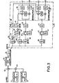
- FIG. 5 gives a first alternative embodiment of the actual measuring device 25 previously described. The numbering of figure 4 is repeated for the common elements which do not are not described again.
- the input of the device 25 is connected in parallel to different constituent circuits, namely at the inputs of the bandpass filters 28, 29, 32, and at the input of a bandpass filter 36 which is centered on the frequency F1 + F2. It is therefore the component of order 2 at the frequency F1 + F2 and the component of order 3 at the frequency 2xF1-F2 which will be measured.
- the known non-linear element is here a threshold comparator associated with an "exclusive OR" logic circuit, the assembly being represented on the figure by a multiplier 37 or 40, the "exclusive OR” being able to be assimilated to a binary multiplier.
- the outputs of filters 28 and 29 are respectively connected to a 1st input and to a 2nd input of circuit 37 which realizes, through the threshold comparator, a "binarization” of each of these signals then, via the "exclusive OR", a multiplication of these binary signals.
- the output of the multiplier is connected to a 1st filter 38 which selects the signal at frequency F1 + F2, then transmitted on the modulation input of the synchronous detection circuit 27, as well as to a 2nd filter 39 which selects the signal at the frequency F1-F2.
- the signal analog output of this filter 39 is sent to the input of a second multiplier 40 of the same type as the previous one, the 2nd entry being powered by the signal at the output of filter 28.
- the frequency signal 2xF1-F2 which is selected by a bandpass filter 41 centered on this frequency. It is then transmitted on the entry modulation of the synchronous detection circuit 35.
- the quadrature detectors used generally produce signals over which continuous components are superimposed. Now these half ers can in some cases distort the measure. That's why we uses a switchable notch filter which, by eliminating intermodulation, identifies the offsets of the continuous components. We can then by calculation correct the measurements (made without notch filter) subtracting the values of the continuous components measured when the notch filters were selected.
- the 2nd order component at the frequency F1 + F2 in output of filter 36 passes through a switch 42 which makes it possible to connect or not in series a filter 43 rejector of the frequency F1 + F2. Leaving the switch is connected to the input of a frequency bandpass filter 44 F1 + F2 control unit and placed as far upstream as possible in order to eliminate interference signals picked up on the line.
- This filter is identical or even more selective than filter 36. Its role is to filter the noise of the chain amplification and intermodulation products intrinsic to it, chain not shown in Figure 5 but generally necessary behind the filters for selecting intermodulation products. Leaving the filter is connected to the signal input of the synchronous demodulation circuit 27.
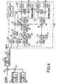
- Synchronous detection circuits can operate at relatively low frequencies, despite high frequencies F1 and F2 often imposed by the non-linear device.
- the known non-linear devices here are not logic circuits but analog multipliers, the operating frequencies being higher.
- the components of intermodulation products from a known non-linear device are used not to modulate synchronous detection circuits but to transpose the intermodulation products to be measured at a frequency single F3, frequency chosen for the operation of the synchronous detection.
- Filters 28 and 29 allow the two frequencies to be recovered F1 and F2 drivers then transmitted on the two inputs of a multiplier analog 48.
- the bandpass filter 49 extracts products intermodutation delivered by the multiplier, the frequency signal F1-F2.
- An oscillator 50 delivers a signal at a frequency F3 which is the operating frequency chosen for the detection circuits synchronous.
- a multiplier 51 allows to transpose the component of 2nd frequency order F1-F2 at frequency F1-F2-F3.
- the output of the filter 49 is connected to a 1st input of the multiplier and the output of oscillator 50 is connected to a 2nd input.
- the transposed signal is filtered at output via a bandpass filter 52 centered on F1-F2-F3.
- the 2nd order component to be measured F1-F2 is filtered by the bandpass filter 26 then passes through a switch 53 which has the role of allow the serial connection of a frequency rejector filter 54 F1-F2 for the reasons previously explained. It then feeds a analog multiplier 55 on a 1st input, the 2nd input receiving the signal F1-F2-F3 from filter 52.
- a bandpass filter 56 centered on F3 is connected to the output of the multiplier and provides the input of the circuit synchronous detection 27 the 2nd order component to be measured, transposed to frequency F3.
- the 3rd order component to be measured 2xF1-F2 is filtered by the bandpass filter 32 then passes through a switch 45 which has the role of allow the serial connection of a filter 46 frequency rejector 2xF1-F2 for the reasons explained above. Then it feeds an analog multiplier 57 on a 1st input, the 2nd input receiving the signal at frequency F1 coming from the filter 28.
- a bandpass filter 58 centered on F1-F2 is connected to the output of the multiplier and selects the 2xF1-F2 component transposed to frequency F1-F2.
- Filter outlet 58 is connected to the 1st input of an analog multiplier 59, the 2nd input being connected to the output of the filter 52.
- a bandpass filter 60 centered on F3 is connected to the output of the multiplier and provides the input of the synchronous detection circuit 35, which is identical to circuit 27, the 3rd order component to be measured, transposed to frequency F3.
- the different transpositions are made from non-linear devices known, the relationships between the signal and the input of a non-linear device known to the signal transposed at the output therefore being known. So, knowing the value of the 2xF1-F2 signal is equivalent to measuring the transposed signal F3.
- the dynamics of the device is linked to the width of the preselection filter which lets through a power noise proportional to its bandwidth.
- This noise may have 30 dB more power than intermodulation power and saturate the inputs of the quadrature detectors.
- the choice judicious pilot frequencies allows the use of quartz filters or standard ceramic filters, which reduces the cost of making the device.
- the filters F3 used in the device of FIG. 6 are quartz filters of the type used in frequency circuits FM receivers, 10.7 MHz center frequency and bandwidth of the order of 5 to 6 KHz.
- the frequencies of the intermodulation products are chosen from so as to use synchronous detection circuits operating at relatively low frequencies because of a reduced cost and giving a better sensitivity. So, we will rather choose a frequency difference (F1-F2) rather than a sum (F1 + F2) if the values of F1 and F2 are high.
- a particular application of the invention previously described relates to a device for transmitting analog signals over fiber optical, for example in the context of the transmission of television.
- the diagram of integration of the detection and correction of non-linearity objects of the invention is shown in the figure 7.
- an emission head made up of an associated laser 61 to an external optical modulator 62.
- the latter includes a device for integrated linearization which can be controlled via voltages control. These voltages are applied to modulator 62 by via a controller 63 which uses the measurements performed by a non-linearity estimation device 64.
- the pilot frequencies are generated by a generator 65 to be transmitted to a first input of an adder 66.
- the second input of this adder receives the "useful" signal modulation signal optical.
- the output of the adder is connected to the modulation input of the optical modulator 62.
- a coupler is connected at the output of the modulator optics 67 whose direct output is the modulated output used and whose coupled output is connected to an optical receiver 68.
- This receiver translates the optical signal into electrical signal, signal transmitted to the input of the device measuring device 64.
- This measuring device is for example device 25.
- the input signal is the modulated optical signal transformed into an electrical signal and therefore comprising the pilot frequencies.
- the output of this circuit is consists of pairs of I and Q signals whose number corresponds to that of the components measured by the device 64, number function by example of the inputs available on the non-linear device. All optical receiver circuits 68, measuring device 64, command 63 represents the control loop.
Description
L'invention concerne les circuits non-linéaires et plus particulièrement les dispositifs de correction de linéarité de tels circuits.The invention relates to non-linear circuits and more particularly the linearity correction devices of such circuits.
Elle s'applique par exemple aux circuits de modulation d'un signal optique provenant d'un laser pour la transmission de signaux sur fibre optique. Cette modulation, réalisée à l'aide d'un modulateur externe branché en sortie du laser, est source de non-linéarité.It applies for example to the modulation circuits of a optical signal from a laser for signal transmission on optical fiber. This modulation, carried out using an external modulator connected to the laser output, is a source of non-linearity.
Les systèmes de transmission d'un signal sont généralement sensibles à la non-linéarité des différents éléments qui les constituent. Si la non-linéarité de ces éléments est imposée par la physique, il reste malgré tout possible d'ajouter des dispositifs de linéarisation afin d'améliorer les performances globales du système. On doit dans ce cas disposer d'un moyen de mesure des non-linéarités résiduelles du système à corriger pour pouvoir optimiser les paramètres du dispositif de linéarisation. Si de plus les non-linéarités du système sont appelées à évoluer dans le temps, le dispositif de mesure doit être intégré au système pour réagir en temps réel sur les dispositifs de linéarisation.Signal transmission systems are generally sensitive to the non-linearity of the various elements which constitute them. If the non-linearity of these elements is imposed by physics, it remains despite everything possible to add linearization devices to improve the overall system performance. In this case we must have a means for measuring the residual non-linearities of the system to be corrected for be able to optimize the parameters of the linearization device. If more the non-linearities of the system are called to evolve over time, the measuring device must be integrated into the system to react in real time on linearization devices.
Un moyen connu d'estimation de la non-linéarité consiste en l'utilisation d'un ou plusieurs signaux pilotes. La figure 1 représente un tel dispositif selon l'art antérieur.A known means of estimating non-linearity consists of the use of one or more pilot signals. Figure 1 shows such a device according to the prior art.
Le signal pilote, le plus souvent sinusoïdal, est généré par un oscillateur ou générateur de pilote 1. Ce signal est envoyé sur une deuxième entrée d'un additionneur 2 dont la première entrée est alimentée par le signal à transmettre ou signal utile. Le dispositif non-linéaire dont on cherche à corriger les effets gênants dus à la non-linéarité est branché en aval du générateur de fréquence pilote, par exemple en sortie de l'additionneur 2. Un coupleur 4 est branché en sortie du dispositif non-linéaire pour prélever, sur sa sortie couplée, les intermodulations créées par ce dernier. La sortie directe du coupleur fournit le signal à exploiter, qui sera éventuellement filtré pour être débarrassé du signal pilote précédemment ajouté. Le signal prélevé sur la sortie couplée est transmis à l'entrée d'une voie de mesure des signaux d'intermodulation de deuxième ordre ou de plusieurs voies de mesure de signaux d'intermodulation d'ordres successifs, par exemple deux voies sur le schéma. Chacune des voies est constituée d'un premier filtre passe-bande 5.1, 5.2, qui a pour rôle de sélectionner l'harmonique dont la fréquence correspond à l'ordre d'intermodulation de la voie, suivi d'un détecteur 6.1, 6.2, qui mesure l'amplitude ou la puissance du signal filtré. Le détecteur peut être une simple diode ou un dispositif associant une résistance et une mesure de température tel qu'un bolomètre. La sortie du détecteur est reliée à un filtre passe-bas 7.1, 7.2, qui élimine les fréquences parasites. La sortie de chacune des voies (ou de la voie de mesure dans le cas ou elle est unique) est reliée à un dispositif de commande 8, lui même relié au dispositif non-linéaire. Ce dispositif de commande transforme les signaux reçus en signaux de commande adaptés aux entrées de correction de non-linéarité du dispositif non-linéaire.The pilot signal, most often sinusoidal, is generated by a oscillator or pilot generator 1. This signal is sent on a second input of an adder 2, the first input of which is supplied by the signal to be transmitted or useful signal. The non-linear device of which seeks to correct the annoying effects due to non-linearity is connected in downstream of the pilot frequency generator, for example at the output of the adder 2. A coupler 4 is connected at the output of the non-linear device to take, on its coupled output, the intermodulations created by this last. The direct output of the coupler provides the signal to be exploited, which will be possibly filtered to get rid of the pilot signal previously added. The signal taken from the coupled output is transmitted to the input of a second order intermodulation signal measurement channel or several measurement channels of intermodulation signals of successive orders, by example two ways on the diagram. Each channel consists of a first bandpass filter 5.1, 5.2, which has the role of selecting the harmonic whose frequency corresponds to the intermodulation order of the channel, followed by a 6.1 detector, 6.2, which measures the amplitude or the power of the filtered signal. The detector can be a simple diode or a device combining a resistance and a measurement of temperature such as a bolometer. The detector output is connected to a low-pass filter 7.1, 7.2, which eliminates spurious frequencies. The output of each channel (or the measurement channel if it is unique) is connected to a device command 8, itself connected to the non-linear device. This control device transforms the received signals into control signals adapted to the inputs of correction of non-linearity of the non-linear device.
Les dispositifs de ce type souffrent d'inconvénients majeurs. Ils ne peuvent pas donner d'informations sur la phase des intermodulations et ils sont peu sensibles, en particulier lorsque le dispositif t ravaille e n présence d e bruit. Ils ne conviennent pas si les niveaux des produits d'intermodulation, c'est à dire les non-linéarités à mesurer sont très faibles.Devices of this type suffer from major drawbacks. They don't cannot provide information on the intermodulation phase and they are few sensitive, in particular when the device works in the presence of noise. They don't not suitable if the levels of the intermodulation products, i.e. the non-linearities to measure are very small.
Une amélioration de cette sensibilité, pour des dispositifs de ce type, se heurte à un coût prohibitif. En effet, un filtrage efficace des produits d'intermodulation nécessiterait non seulement l'utilisation de filtres de bruit 5.1, 5.2 de haute performance, donc de réalisation délicate, mais également d'un signal pilote parfaitement stable en fréquence.An improvement in this sensitivity, for devices of this type, is comes at a prohibitive cost. Indeed, effective filtering of products intermodulation would require not only the use of noise filters 5.1, 5.2 high performance, therefore delicate, but also a signal driver perfectly stable in frequency.
L'article de JOURNAL OF LIGHTWAVE TECHNOLOGY, vol.11, n°1, janvier 1993, NEW YORK US, pages 82-104, NAZARATHY et Al., intitulé « Progress in extemally modulated AM CATV transmission systems », dévoile un dispositif d'estimation de non-linéarité pour un dispositif de transmission optique. L'article montre l'utilisation de signaux pilotes en combinaison avec un circuit de détection synchrone. Cependant, le dispositif d'estimation doit être placé à proximité du modulateur afin d'utiliser les mêmes signaux pilotes et ne permet pas d'être déporté à une longue distance de manière aisée.The article from JOURNAL OF LIGHTWAVE TECHNOLOGY, vol.11, n ° 1, January 1993, NEW YORK US, pages 82-104, NAZARATHY et al., titled "Progress in extemally modulated AM CATV transmission systems", reveals a non-linearity estimation device for an optical transmission device. The article shows the use of pilot signals in combination with a circuit synchronous detection. However, the estimator should be placed at proximity of the modulator in order to use the same pilot signals and does not allow to be deported a long distance easily.
La présente invention a pour but de pallier les inconvénients précités. Elle a pour objet un procédé d'estimation de non-linéarité d'un dispositif consistant à générer un ou plusieurs signaux pilotes en amont du dispositif pour la mesure de composantes de leurs produits d'intermodulation en sortie de ce dispositif. L'invention se caractérise plus particulièrement comme indiqué dans les revendications annexées. The present invention aims to overcome the aforementioned drawbacks. It relates to a method of estimating non-linearity of a device consisting in generate one or more pilot signals upstream of the device for the measurement of components of their intermodulation products at the output of this device. The invention is more particularly characterized as indicated in the appended claims.
Elle a pour avantage de permettre une correction plus rapide du dispositif non-linéaire du fait de l'information de phase. La sensibilité du dispositif d'estimation est améliorée et le coût est réduit du fait de l'utilisation de filtres standards et de contraintes réduites sur les signaux pilotes.It has the advantage of allowing faster correction of the non-linear device due to phase information. The sensitivity of the estimation device is improved and the cost is reduced due to the use of standard filters and reduced constraints on signals drivers.
Les caractéristiques et avantages de la présente invention ressortiront mieux de la description suivante donnée à titre d'exemple non limitatif et en référence aux figures annexées où :
- La figure 1 représente un dispositif de mesure de non-linéarité selon l'art antérieur.
- La figure 2 représente, dans son principe, un dispositif de mesure de non-linéarité selon l'invention.
- La figure 3 représente une variante de ce dispositif.
- La figure 4 représente un dispositif de mesure de non linéarité prenant en compte des produits d'intermodulation du 2ème et 3ème ordre.
- La figure 5 représente un 1er exemple de réalisation.
- La figure 6 représente un 2ème exemple de réalisation.
- La figure 7 représente une application du dispositif de mesure de non-linéarité.
- FIG. 1 represents a device for measuring non-linearity according to the prior art.
- FIG. 2 shows, in principle, a device for measuring non-linearity according to the invention.
- Figure 3 shows a variant of this device.
- FIG. 4 represents a device for measuring non-linearity taking into account 2nd and 3rd order intermodulation products.
- FIG. 5 represents a first example of embodiment.
- FIG. 6 represents a second example of embodiment.
- FIG. 7 represents an application of the non-linearity measuring device.
Le dispositif selon l'invention est représenté à la figure 2. Il utilise, comme les dispositifs connus, un signal pilote injecté en amont du dispositif non-linéaire à mesurer. Le signal utile devant alimenter le dispositif non-linéaire est préalablement transmis à une première entrée d'un additionneur 9. La deuxième entrée est, comme précédemment décrit, alimentée par un générateur de pilote 10 qui génère un signal, par exemple sinusoïdal, de fréquence comprise dans la bande passante du dispositif non-linéaire. La sortie de l'additionneur est reliée à l'entrée du dispositif non-linéaire 11 dont on cherche à corriger la non-linéarité. La sortie du dispositif non-linéaire est reliée à un coupleur 12 dont la voie directe fournit le signal utile. Ce signal est ensuite éventuellement filtré par les circuits aval pour en éliminer le signal pilote si nécessaire.The device according to the invention is shown in Figure 2. It uses, like the known devices, a pilot signal injected upstream of the non-linear device to be measured. The useful signal to supply the non-linear device is previously transmitted to a first input an adder 9. The second entry is, as previously described, powered by a pilot generator 10 which generates a signal, for example sinusoidal, of frequency included in the bandwidth of the device non-linear. The output of the adder is connected to the input of the device non-linear 11 whose non-linearity is sought to be corrected. Leaving the non-linear device is connected to a coupler 12 whose direct path provides the useful signal. This signal is then optionally filtered by the circuits downstream to eliminate the pilot signal if necessary.
La sortie couplée est reliée à un dispositif de mesure proprement dit 13 représenté en traits pointillés sur le schéma. Ce dispositif réalise la détection des non-linéarités d'une manière nouvelle. The coupled output is connected to a measuring device proper 13 shown in dotted lines in the diagram. This device performs the detection of non-linearities in a new way.
Le signal transmis par la voie couplée alimente un premier filtre passe-bande 14 qui a pour rôle de sélectionner par filtrage le signal pilote. Sa sortie est reliée à l'entrée d'un dispositif non-linéaire connu 15, c'est à dire dont on connaít les caractéristiques non-linéaires, par exemple les coefficients de sa fonction de transfert. Ce dispositif génère des signaux d'intermodulation à la même fréquence que ceux générés par le dispositif non linéaire 11. Le signal d'intermodulation d'ordre 2 est extrait du signal disponible en sortie grâce à un filtre passe-bande 16 branché en sortie du dispositif. Il est ensuite transmis sur l'entrée modulation d'un circuit de détection synchrone à deux voies en quadrature 17 représenté en pointillés sur le schéma.The signal transmitted by the coupled channel feeds a first filter bandpass 14 which has the role of selecting by filtering the pilot signal. Its output is connected to the input of a known non-linear device 15, that is to say which we know the non-linear characteristics, for example the coefficients of its transfer function. This device generates signals intermodulation at the same frequency as those generated by the device nonlinear 11. Intermodulation signal of order 2 is extracted from the signal available at the output thanks to a bandpass filter 16 connected to the output of the device. It is then transmitted to the modulation input of a two-way synchronous detection in quadrature 17 shown in dotted lines on the diagram.
Le signal transmis par la voie couplée alimente également un deuxième filtre passe-bande 18 qui a pour rôle de sélectionner par filtrage le signal d'intermodulation que l'on souhaite mesurer, c'est à dire celui d'ordre 2 provenant du dispositif non-linéaire 11. La sortie de ce filtre alimente, par l'entrée signal du circuit de détection synchrone 17, chacune des deux voies de ce circuit décrit ci-après.The signal transmitted by the coupled channel also feeds a second bandpass filter 18 which has the role of selecting by filtering the intermodulation signal that we want to measure, i.e. the one of order 2 from the non-linear device 11. The output of this filter feeds, via the signal input of the synchronous detection circuit 17, each of the two paths of this circuit described below.
Le circuit de détection synchrone est constitué de deux multiplieurs 19 et 20 dont chaque première entrée reçoit le signal provenant du filtre 18. La deuxième entrée est alimentée, pour le premier multiplieur 19 par le signal provenant du filtre 16 et pour le deuxième multiplieur 20 par ce signal déphasé de Π / 2, ce signal traversant un circuit déphaseur 21 avant d'attaquer le multiplieur 20. Les sorties des multiplieurs 19 et 20 sont respectivement reliées aux filtres passe-bas 22 et 23 qui ont pour rôle de filtrer la seule composante continue. Les deux sorties correspondantes sont les sorties en quadrature I et Q du circuit de détection synchrone permettant de mesurer l'amplitude et la phase de l'intermodulation recherchée.The synchronous detection circuit consists of two multipliers 19 and 20 of which each first input receives the signal from filter 18. The second input is supplied, for the first multiplier 19 by the signal from filter 16 and for the second multiplier 20 by this signal phase shifted by Π / 2, this signal crossing a phase shifting circuit 21 before attacking the multiplier 20. The outputs of the multipliers 19 and 20 are respectively connected to low-pass filters 22 and 23 which have the role of filtering the only continuous component. Both corresponding outputs are the quadrature outputs I and Q of the synchronous detection to measure the amplitude and phase of the intermodulation sought.
La détection synchrone permet de réduire considérablement la complexité des filtres. En effet le filtre passe-bande 18 de présélection de l'intermodulation n'a pas besoin d'être très sélectif, son rôle étant uniquement d'empêcher la saturation du circuit de détection synchrone par les signaux utiles et le signal pilote. La sélectivité est quant à elle procurée par les filtres passe-bas 22 et 23 placés à la sortie des détecteurs.Synchronous detection significantly reduces the complexity of filters. Indeed, the bandpass filter 18 for preselection of intermodulation does not need to be very selective, its role being only to prevent saturation of the synchronous detection circuit by the useful signals and the pilot signal. Selectivity is provided by low-pass filters 22 and 23 placed at the output of the detectors.
Soit ω1 la pulsation du signal pilote. Let ω 1 be the pulsation of the pilot signal.
Le signal de modulation sur la 2ème entrée du circuit de
détection synchrone est connu puisqu'il s'agit de l'harmonique 2 d'un signal
pilote connu de pulsation ω1 délivrée par un dispositif non-linéaire de
caractéristiques connues :
Ab et ϕb étant les amplitudes et phases de l'harmonique 2 générée par le dispositif non-linéaire connu 15.A b and ϕ b being the amplitudes and phases of the harmonic 2 generated by the known non-linear device 15.
Le signal provenant du filtre 18 a pour valeur :
Ac et ϕc étant les amplitudes et phases de l'harmonique 2 générée par le dispositif non-linéaire 11.A c and ϕ c being the amplitudes and phases of the harmonic 2 generated by the non-linear device 11.
La composante continue du signal B x C correspondant à la
sortie I a pour valeur :
Celle correspondant à la sortie Q a pour valeur (déphasage du
signal B de π/2) :
Ainsi, la mesure de l'amplitude de la composante continue de ces signaux permet de connaítre la phase ϕc et l'amplitude Ac du signal d'intermodulation d'ordre 2 provenant du dispositif non-linéaire 11.Thus, the measurement of the amplitude of the DC component of these signals makes it possible to know the phase ϕ c and the amplitude A c of the intermodulation signal of order 2 coming from the non-linear device 11.
Ce dispositif peut évidemment être étendu aux mesures de signaux d'intermodulation d'ordres supérieurs, les filtres 16 et 18 étant adaptés en conséquence pour filtrer ces signaux.This device can obviously be extended to measurements of higher order intermodulation signals, filters 16 and 18 being adapted accordingly to filter these signals.
La figure 3 représente une variante du dispositif précédemment décrit. Au lieu de regénérer le signal pilote transmis au dispositif non-linéaire connu en prélevant une partie du signal à la sortie du dispositif non-linéaire 11 et en le filtrant par l'intermédiaire du filtre 14, le signal provenant du générateur de pilote est ici directement transmis au dispositif non-linéaire connu 15.Figure 3 shows a variant of the device previously described. Instead of regenerating the pilot signal transmitted to the non-linear device known by taking part of the signal at the device output non-linear 11 and by filtering it through filter 14, the signal from the pilot generator is here directly transmitted to the device known non-linear 15.
La même numérotation est reprise pour les éléments identiques. Le générateur de pilote 10 est relié à la deuxième entrée de l'additionneur 9 et simultanément à l'entrée du dispositif non-linéaire connu 15. Le filtre 14 n'est ici plus nécessaire. The same numbering is used for identical elements. The pilot generator 10 is connected to the second input of the adder 9 and simultaneously with the input of the known non-linear device 15. The filter 14 is no longer necessary here.
Ainsi, en résumé, le dispositif non-linéaire connu utilise le signal pilote soit en le prélevant avant injection dans le dispositif non-linéaire 11 soit en le regénérant à la sortie de celui-ci grâce à un coupleur 12 et à des filtres 14, cette dernière solution présentant l'avantage de dissocier le dispositif de mesure du dispositif d'injection des pilotes.So, in summary, the known non-linear device uses the signal pilot either by taking it before injection into the non-linear device 11 either by regenerating it at the outlet thereof using a coupler 12 and filters 14, this latter solution having the advantage of dissociating the pilot injection device measurement device.
Les figures 2 et 3 montrent le principe de mesure de produits d'intermodulation liés à la génération d'une seule fréquence pilote, produits d'intermodulation correspondant aux harmoniques du signal pilote.Figures 2 and 3 show the principle of product measurement intermodulation related to the generation of a single pilot frequency, products intermodulation corresponding to the harmonics of the pilot signal.
Il est cependant tout aussi envisageable et même plus avantageux, comme expliqué plus loin, de mesurer des produits d'intermodulation de plusieurs signaux pilotes en générant non pas une mais plusieurs fréquences pilotes. La figure 4 représente un dispositif pour de telles mesures.It is however just as possible and even more advantageous, as explained below, to measure products intermodulation of several pilot signals by generating not a but several pilot frequencies. Figure 4 shows a device for such measures.
Un 1er générateur de pilote 19 transmet sur une première entrée d'un additionneur 21 un signal de fréquence F1, un deuxième générateur de pilote 20 alimente la 2ème entrée de cet additionneur par un signal de fréquence F2. La sortie de l'additionneur est envoyée sur une deuxième entrée d'un deuxième additionneur 22 dont la 1ère entrée reçoit le signal utile. La sortie de l'additionneur est reliée à l'entrée du dispositif non-linéaire 23. La sortie de ce dispositif attaque un coupleur 24 dont la voie principale fournit le signal utile et dont la voie couplée fournit une partie de ce signal qui est exploitée par le dispositif de mesure de non-linéarité proprement dit 25 représenté en pointillés sur le schéma et décrit ci-après.A 1st pilot generator 19 transmits on a first input an adder 21 a frequency signal F1, a second generator of pilot 20 supplies the 2nd input of this adder with a signal frequency F2. The output of the adder is sent to a second input of a second adder 22 whose 1st input receives the signal useful. The output of the adder is connected to the input of the non-linear device 23. The output of this device attacks a coupler 24 whose path main provides the useful signal and whose coupled channel provides part of this signal which is used by the non-linearity measuring device proper 25 shown in dotted lines in the diagram and described below.
Ce dispositif, dans notre exemple, mesure l'intermodutation d'ordre deux à la fréquence F1-F2 et l'intermodulation d'ordre trois à la fréquence 2xF1-F2.This device, in our example, measures intermodutation of order two at the frequency F1-F2 and intermodulation of order three at the frequency 2xF1-F2.
Pour ce faire, l'entrée du dispositif 25 est reliée à différents circuits le constituant et d'abord à un 1er filtre passe-bande 26 dont la fréquence centrale est F1-F2. Ce filtre transmet le signal correspondant à cette fréquence à l'entrée d'un circuit de démodulation synchrone 27 identique dans sa structure au circuit 17 décrit à la figure 2.To do this, the input of the device 25 is connected to different constituent circuits and first to a 1st bandpass filter 26 whose center frequency is F1-F2. This filter transmits the signal corresponding to this frequency at the input of a synchronous demodulation circuit 27 identical in structure to circuit 17 described in FIG. 2.
L'entrée du dispositif 25 est également reliée à l'entrée d'un filtre passe-bande 28 de fréquence centrale F1 et à l'entrée d'un filtre passe-bande 29 de fréquence centrale F2. Les sorties des filtres 28 et 29 sont respectivement reliées à une 1ère et à une 2ème entrée d'un multiplieur analogique 30. Ainsi, les signaux pilotes F1 et F2 restitués par les filtres sont mélangés pour générer, en sortie du multiplieur 30, des produits d'intermodulation. Un filtre 31, branché en sa sortie, de type passe-bande et centré sur la fréquence F1-F2, sélectionne le signal à cette fréquence pour le transmettre sur l'entrée modulation du circuit de détection synchrone 27.The input of the device 25 is also connected to the input of a filter bandpass 28 of central frequency F1 and at the input of a bandpass filter 29 of central frequency F2. The outputs of filters 28 and 29 are respectively connected to a 1st and a 2nd input of a multiplier analog 30. Thus, the pilot signals F1 and F2 restored by the filters are mixed to generate, at the output of the multiplier 30, products intermodulation. A filter 31, connected at its output, of the bandpass type and centered on the frequency F1-F2, selects the signal at this frequency to transmit it on the modulation input of the detection circuit synchronous 27.
Le dispositif non-linéaire de caractéristiques connues est ici le multiplieur 30. Les paramètres du signal utilisé pour détecter l'intermodulation d'ordre deux de fréquence F1-F2 sont donc connus. En d'autres termes, l'amplitude et la phase du signal de modulation F1-F2, connaissant les caractéristiques des signaux pilotes et des circuits non linéaires générant ce signal, sont connues.The non-linear device of known characteristics is here the multiplier 30. The parameters of the signal used to detect the intermodulation of order two of frequency F1-F2 are therefore known. In in other words, the amplitude and the phase of the modulation signal F1-F2, knowing the characteristics of pilot signals and circuits not linear generating this signal are known.
La voie mesurant l'intermodulation d'ordre trois à la fréquence 2xF1-F2 est réalisée de manière originale, permettant d'utiliser un détecteur synchrone et un signal de modulation identiques à ceux de la voie d'ordre 2.Channel measuring order three intermodulation at frequency 2xF1-F2 is performed in an original way, allowing the use of a synchronous detector and a modulation signal identical to those of the order track 2.
L'entrée du dispositif 25 est reliée à l'entrée d'un filtre passe-bande 32 de fréquence centrale 2F1-F2 et la sortie de ce filtre est reliée à une 1ère entrée d'un deuxième multiplieur 33. La deuxième entrée du multiplieur est branchée sur la sortie du filtre 28. La sortie du multiplieur est reliée à l'entrée d'un filtre passe-bande dont la fréquence centrale est F1-F2. C'est le signal en sortie de ce filtre qui alimente l'entrée signal d'un 2ème circuit de détection synchrone 35 identique au précédent. L'entrée modulation de ce circuit reçoit, comme pour le circuit 27, le signal en sortie du filtre 31.The input of the device 25 is connected to the input of a bandpass filter 32 of central frequency 2F1-F2 and the output of this filter is connected to a 1st entry of a second multiplier 33. The second entry of multiplier is connected to the output of filter 28. The multiplier output is connected to the input of a bandpass filter whose central frequency is F1-F2. It is the signal at the output of this filter which feeds the signal input of a 2nd synchronous detection circuit 35 identical to the previous one. The entrance modulation of this circuit receives, as for circuit 27, the output signal of filter 31.
Ainsi, l'intermodulation se trouvant à la fréquence 2xF1-F2 est transposée à la fréquence F1-F2 grâce à un 2ème multiplieur analogique de caractéristiques connues utilisant le pilote à la fréquence F1, cette intermodulation pouvant alors être traitée de la même façon que l'intermodulation d'ordre deux. La mesure de signal transposé F1-F2 permet de connaítre la valeur de la composante 2xF1-F2, la relation entre ces signaux étant connue. Ce procédé est équivalent à une détection synchrone par un signal de fréquence 2xF1-F2.Thus, the intermodulation being at the frequency 2xF1-F2 is transposed to frequency F1-F2 thanks to a 2nd analog multiplier of known characteristics using the pilot at the frequency F1, this intermodulation can then be treated in the same way as intermodulation of order two. Signal measurement transposed F1-F2 lets you know the value of the component 2xF1-F2, the relationship between these signals being known. This process is equivalent to a detection synchronous with a 2xF1-F2 frequency signal.
La solution décrite dans cet exemple apporte de nombreux avantages du fait qu'elle permet une plus grande souplesse à la fois dans le choix des fréquences pilotes et des fréquences correspondant aux différents ordres des produits d'intermodulation. Dans les dispositifs précédemment décrits, il est nécessaire que la fréquence pilote et les produits d'intermodulation à mesurer se trouvent simultanément dans la bande passante du dispositif non-linéaire, ce qui n'est pas toujours réalisable.The solution described in this example provides many advantages of allowing more flexibility in both the choice of pilot frequencies and frequencies corresponding to different orders of intermodulation products. In the devices previously described, it is necessary that the pilot frequency and the intermodulation products to be measured are found simultaneously in the bandwidth of the non-linear device, which is not always feasible.
Ici, il est possible de choisir des fréquences pilotes et des fréquences d'intermodulation se trouvant simultanément dans la bande passante du dispositif non-linéaire. Elles peuvent être choisies en dehors de la bande utile c'est à dire de la bande effectivement utilisée par le signal utile. Il est possible de générer des produits d'intermodulation à des fréquences basses. Ainsi, les fréquences des pilotes F1 et F2 peuvent être élevées mais choisissant ces fréquences pilote proches l'une de l'autre, la fréquence de l'intermodulation d'ordre deux qui se trouve à F1-F2 peut être relativement basse, ce qui rend les détecteurs simples à réaliser.Here it is possible to choose pilot frequencies and intermodulation frequencies in the band simultaneously bandwidth of the non-linear device. They can be chosen outside useful band, i.e. the band actually used by the signal useful. It is possible to generate intermodulation products at low frequencies. Thus, the frequencies of the F1 and F2 pilots can be but choosing these pilot frequencies close to each other, the frequency of the second order intermodulation found at F1-F2 can be relatively low, which makes the detectors simple to produce.
Il est d'autre part souhaitable que l'estimation de non-linéarité se
fasse à des fréquences qui ne soient pas trop éloignées de celles
correspondant aux produits d'intermodulation réels, c'est à dire dus au
signal utile. La non-linéarité est en effet fonction de la fréquence et les
coefficients a1, a2.... de la fonction de transfert liant la tension d'entrée vi
du dispositif non-linéaire à sa tension de sortie
Le fait de pouvoir choisir deux ou plusieurs points dans la bande passante du dispositif permet d'obtenir des coefficients représentatifs, en moyenne, des fréquences correspondant aux produits d'intermodulation réels.Being able to choose two or more points in the band bandwidth of the device makes it possible to obtain representative coefficients, in average, frequencies corresponding to intermodulation products real.
Enfin, les niveaux des composantes correspondant à une combinaison des fréquences pilotes peuvent être plus élevés et donc plus faciles à mesurer que ceux correspondant aux harmoniques, le rapport d'amplitude étant de 2 ou 3 pour des composantes du 2ème ou du 3ème ordre et pour des amplitudes de pilote égales.Finally, the levels of the components corresponding to a combination of pilot frequencies may be higher and therefore more easier to measure than those corresponding to harmonics, the ratio amplitude being 2 or 3 for components of the 2nd or 3rd order and for equal pilot amplitudes.
La figure 5 donne une première variante de réalisation du dispositif de mesure proprement dit 25 précédemment décrit. La numérotation de la figure 4 est reprise pour les éléments commun qui ne sont pas à nouveau décrits.FIG. 5 gives a first alternative embodiment of the actual measuring device 25 previously described. The numbering of figure 4 is repeated for the common elements which do not are not described again.
L'entrée du dispositif 25 est reliée en parallèle à différents circuits le constituant, à savoir aux entrées des filtres passe-bande 28, 29, 32, et à l'entrée d'un filtre passe-bande 36 qui est centré sur la fréquence F1+F2. C'est donc la composante d'ordre 2 à la fréquence F1+F2 et la composante d'ordre 3 à la fréquence 2xF1-F2 qui vont être mesurées.The input of the device 25 is connected in parallel to different constituent circuits, namely at the inputs of the bandpass filters 28, 29, 32, and at the input of a bandpass filter 36 which is centered on the frequency F1 + F2. It is therefore the component of order 2 at the frequency F1 + F2 and the component of order 3 at the frequency 2xF1-F2 which will be measured.
L'élément non-linéaire connu est ici un comparateur à seuil associé à un circuit logique "OU exclusif", l'ensemble étant représenté sur la figure par un multiplieur 37 ou 40, le "OU exclusif" pouvant être assimilé à un multiplieur binaire. Les sorties des filtres 28 et 29 sont respectivement reliées à une 1ère entrée et à une 2ème entrée du circuit 37 qui réalise, par l'intermédiaire du comparateur à seuil, une "binarisation" de chacun de ces signaux puis, par l'intermédiaire du "OU exclusif", une multiplication de ces signaux binaires. On peut assimiler le comparateur à un générateur d'harmoniques et le multiplieur à un générateur de produits d'intermodulation. Ces nombreux produits d'intermodulation doivent donc être filtrés. Pour ce faire, la sortie du multiplieur est reliée à un 1er filtre 38 qui sélectionne le signal à la fréquence F1+F2, ensuite transmis sur l'entrée modulation du circuit de détection synchrone 27, ainsi qu'à un 2ème filtre 39 qui sélectionne le signal à la fréquence F1-F2. Le signal analogique en sortie de ce filtre 39 est envoyé sur l'entrée d'un second multiplieur 40 du même type que le précédent, la 2ème entrée étant alimentée par le signal en sortie du filtre 28. Parmi les produits d'intermodulation générés en sortie du multiplieur 40 se trouve donc le signal de fréquence 2xF1-F2, qui est sélectionné par un filtre passe-bande 41 centré sur cette fréquence. Il est ensuite transmis sur l'entrée modulation du circuit de détection synchrone 35.The known non-linear element is here a threshold comparator associated with an "exclusive OR" logic circuit, the assembly being represented on the figure by a multiplier 37 or 40, the "exclusive OR" being able to be assimilated to a binary multiplier. The outputs of filters 28 and 29 are respectively connected to a 1st input and to a 2nd input of circuit 37 which realizes, through the threshold comparator, a "binarization" of each of these signals then, via the "exclusive OR", a multiplication of these binary signals. We can compare the comparator to a generator of harmonics and the multiplier to a product generator intermodulation. These numerous intermodulation products must therefore be filtered. To do this, the output of the multiplier is connected to a 1st filter 38 which selects the signal at frequency F1 + F2, then transmitted on the modulation input of the synchronous detection circuit 27, as well as to a 2nd filter 39 which selects the signal at the frequency F1-F2. The signal analog output of this filter 39 is sent to the input of a second multiplier 40 of the same type as the previous one, the 2nd entry being powered by the signal at the output of filter 28. Among the products intermodulation generated at the output of multiplier 40 is therefore the frequency signal 2xF1-F2, which is selected by a bandpass filter 41 centered on this frequency. It is then transmitted on the entry modulation of the synchronous detection circuit 35.
Les détecteurs en quadrature utilisés produisent en général des signaux auxquels sont superposées des composantes continues. Or ces demi ères peuvent dans certains cas fausser la mesure. C'est pourquoi on utilise un filtre coupe-bande commutable qui, en éliminant l'intermodulation, permet d'identifier les décalages des composantes continues. On peut alors par calcul corriger les mesures (faites sans filtre coupe-bande) en retranchant les valeurs des composantes continues mesurées quand les filtres coupe-bande étaient sélectionnés.The quadrature detectors used generally produce signals over which continuous components are superimposed. Now these half ers can in some cases distort the measure. That's why we uses a switchable notch filter which, by eliminating intermodulation, identifies the offsets of the continuous components. We can then by calculation correct the measurements (made without notch filter) subtracting the values of the continuous components measured when the notch filters were selected.
Ainsi, la composante de 2ème ordre à la fréquence F1+F2 en sortie du filtre 36 traverse un commutateur 42 qui permet de brancher ou pas en série un filtre 43 réjecteur de la fréquence F1+F2. La sortie du commutateur est reliée à l'entrée d'un filtre passe-bande 44 de fréquence centrale F1+F2 et placé le plus en amont possible afin d'éliminer les signaux d'interférence captés sur la ligne. Ce filtre est identique ou même plus sélectif que le filtre 36. Son rôle est de filtrer le bruit de la chaíne d'amplification et des produits d'intermodulation intrinsèques à celle-ci, chaíne non représentée sur la figure 5 mais généralement nécessaire derrière les filtres de sélection des produits d'intermodulation. La sortie du filtre est reliée à l'entrée signal du circuit de démodulation synchrone 27.Thus, the 2nd order component at the frequency F1 + F2 in output of filter 36 passes through a switch 42 which makes it possible to connect or not in series a filter 43 rejector of the frequency F1 + F2. Leaving the switch is connected to the input of a frequency bandpass filter 44 F1 + F2 control unit and placed as far upstream as possible in order to eliminate interference signals picked up on the line. This filter is identical or even more selective than filter 36. Its role is to filter the noise of the chain amplification and intermodulation products intrinsic to it, chain not shown in Figure 5 but generally necessary behind the filters for selecting intermodulation products. Leaving the filter is connected to the signal input of the synchronous demodulation circuit 27.
De même pour la composante du 3ème ordre à la fréquence 2xF1-F2 en sortie du filtre 32 qui traverse un commutateur 45 permettant de brancher ou non en série un filtre 46 réjecteur de cette fréquence 2xF1-F2. En sortie du commutateur, le signal traverse un filtre passe-bande 47 à la fréquence centrale de 2xF1-F2 avant d'attaquer l'entrée signal du circuit de détection synchrone 35. Ce filtre 47 est, comme indiqué précédemment, un filtre de limitation du spectre de bruit.Likewise for the 3rd order frequency component 2xF1-F2 at the output of filter 32 which passes through a switch 45 allowing to connect or not in series a filter 46 rejector of this frequency 2xF1-F2. At the output of the switch, the signal passes through a bandpass filter 47 to the center frequency of 2xF1-F2 before attacking the signal input of the circuit synchronous detection 35. This filter 47 is, as indicated previously, a noise spectrum limiting filter.
Cette 1ère variante qui vient d'être décrite est principalement
utilisée pour des fréquences basses. Par exemple, dans la réalisation
effectuée :
Ainsi, l'utilisation de filtres passe-bande sélectifs standards et de circuits logiques comme éléments non-linéaires conduit à un dispositif simplement réalisable et peu coûteux.Thus, the use of standard selective bandpass filters and logic circuits as non-linear elements leads to a device simply achievable and inexpensive.
La deuxième variante de réalisation est représentée à la figure
6. Elle est plus adaptée aux fréquences élevées. Par exemple pour notre
réalisation :
Elle utilise une transposition de fréquence supplémentaire qui permet de choisir la fréquence de fonctionnement des démodulations synchrones. On peut ainsi utiliser des filtres passe-bande standards donc de coût modeste, offrant une sélectivité élevée et une très bonne protection vis-à-vis du signal utile et du bruit. Les circuits de détection synchrone peuvent fonctionner à des fréquences relativement basses, malgré les hautes fréquences F1 et F2 souvent imposées par le dispositif non-linéaire. Les dispositifs non-linéaires connus sont ici non pas des circuits logiques mais des multiplieurs analogiques, les fréquences de fonctionnement étant plus élevées.It uses an additional frequency transposition which allows to choose the operating frequency of the demodulations synchronous. We can thus use standard bandpass filters so low cost, offering high selectivity and very good protection vis-à-vis the useful signal and noise. Synchronous detection circuits can operate at relatively low frequencies, despite high frequencies F1 and F2 often imposed by the non-linear device. The known non-linear devices here are not logic circuits but analog multipliers, the operating frequencies being higher.
Contrairement au dispositif précédent, les composantes de produits d'intermodulation provenant d'un dispositif non-linéaire connu sont exploitées non pas pour moduler les circuits de détection synchrone mais pour transposer les produits d'intermodulation à mesurer à une fréquence unique F3, fréquence choisie pour le fonctionnement des circuits de détection synchrone.Unlike the previous device, the components of intermodulation products from a known non-linear device are used not to modulate synchronous detection circuits but to transpose the intermodulation products to be measured at a frequency single F3, frequency chosen for the operation of the synchronous detection.
Les filtres 28 et 29 permettent de récupérer les deux fréquences pilotes F1 et F2 ensuite transmises sur les deux entrées d'un multiplieur analogique 48. En sa sortie, le filtre passe-bande 49 extrait, des produits d'intermodutation délivrés par le multiplieur, le signal de fréquence F1-F2.Filters 28 and 29 allow the two frequencies to be recovered F1 and F2 drivers then transmitted on the two inputs of a multiplier analog 48. At its output, the bandpass filter 49 extracts products intermodutation delivered by the multiplier, the frequency signal F1-F2.
Un oscillateur 50 délivre un signal à une fréquence F3 qui est la fréquence de fonctionnement choisie pour les circuits de détection synchrone. Un multiplieur 51 permet de transposer la composante de 2ème ordre de fréquence F1-F2 à la fréquence F1-F2-F3. Pour cela, la sortie du filtre 49 est reliée à une 1 ère entrée du multiplieur et la sortie de l'oscillateur 50 est reliée à une 2ème entrée. Le signal transposé est filtré en sortie par l'intermédiaire d'un filtre passe-bande 52 centré sur F1-F2-F3.An oscillator 50 delivers a signal at a frequency F3 which is the operating frequency chosen for the detection circuits synchronous. A multiplier 51 allows to transpose the component of 2nd frequency order F1-F2 at frequency F1-F2-F3. For this, the output of the filter 49 is connected to a 1st input of the multiplier and the output of oscillator 50 is connected to a 2nd input. The transposed signal is filtered at output via a bandpass filter 52 centered on F1-F2-F3.
La composante du 2ème ordre à mesurer F1-F2 est filtrée par le filtre passe-bande 26 puis traverse un commutateur 53 qui a pour rôle de permettre le branchement en série d'un filtre 54 réjecteur de la fréquence F1-F2 pour les raisons précédemment expliquées. Elle alimente ensuite un multiplieur analogique 55 sur une 1ère entrée, la 2ème entrée recevant le signal F1-F2-F3 provenant du filtre 52. Un filtre passe-bande 56 centré sur F3 est branché en sortie du multiplieur et fournit à l'entrée du circuit de détection synchrone 27 la composante du 2ème ordre à mesurer, transposée à la fréquence F3. The 2nd order component to be measured F1-F2 is filtered by the bandpass filter 26 then passes through a switch 53 which has the role of allow the serial connection of a frequency rejector filter 54 F1-F2 for the reasons previously explained. It then feeds a analog multiplier 55 on a 1st input, the 2nd input receiving the signal F1-F2-F3 from filter 52. A bandpass filter 56 centered on F3 is connected to the output of the multiplier and provides the input of the circuit synchronous detection 27 the 2nd order component to be measured, transposed to frequency F3.
La composante du 3ème ordre à mesurer 2xF1-F2 est filtrée par le filtre passe-bande 32 puis traverse un commutateur 45 qui a pour rôle de permettre le branchement en série d'un filtre 46 réjecteur de la fréquence 2xF1-F2 pour les raisons précédemment expliquées. Elle alimente ensuite un multiplieur analogique 57 sur une 1ère entrée, la 2ème entrée recevant le signal à la fréquence F1 provenant du filtre 28. Un filtre passe-bande 58 centré sur F1-F2 est branché en sortie du multiplieur et sélectionne la composante 2xF1-F2 transposée à la fréquence F1-F2. La sortie du filtre 58 est reliée à la 1ère entrée d'un multiplieur analogique 59, la 2ème entrée étant branchée sur la sortie du filtre 52. Un filtre passe-bande 60 centré sur F3 est branché en sortie du multiplieur et fournit à l'entrée du circuit de détection synchrone 35, qui est identique au circuit 27, la composante du 3ème ordre à mesurer, transposée à la fréquence F3.The 3rd order component to be measured 2xF1-F2 is filtered by the bandpass filter 32 then passes through a switch 45 which has the role of allow the serial connection of a filter 46 frequency rejector 2xF1-F2 for the reasons explained above. Then it feeds an analog multiplier 57 on a 1st input, the 2nd input receiving the signal at frequency F1 coming from the filter 28. A bandpass filter 58 centered on F1-F2 is connected to the output of the multiplier and selects the 2xF1-F2 component transposed to frequency F1-F2. Filter outlet 58 is connected to the 1st input of an analog multiplier 59, the 2nd input being connected to the output of the filter 52. A bandpass filter 60 centered on F3 is connected to the output of the multiplier and provides the input of the synchronous detection circuit 35, which is identical to circuit 27, the 3rd order component to be measured, transposed to frequency F3.
Les différentes transpositions se font à partir de dispositifs non-linéaires connus, les relations liant le signal à l'entrée d'un dispositif non-linéaire connu au signal transposé en sortie étant donc connues. Ainsi, connaítre la valeur du signal 2xF1-F2 revient à mesurer le signal transposé F3.The different transpositions are made from non-linear devices known, the relationships between the signal and the input of a non-linear device known to the signal transposed at the output therefore being known. So, knowing the value of the 2xF1-F2 signal is equivalent to measuring the transposed signal F3.
Dans les deux variantes décrites, la dynamique du dispositif est liée à la largeur du filtre de présélection qui laisse passer une puissance de bruit proportionnelle à sa largeur de bande passante. Ce bruit peut avoir une puissance supérieure de 30 dB à la puissance de l'intermodulation recherchée et saturer les entrées des détecteurs en quadrature. Le choix judicieux des fréquences des pilotes permet l'utilisation de filtres à quartz ou de filtres céramiques standards, ce qui réduit le coût de réalisation du dispositif. Ainsi, les filtres F3 utilisés dans le dispositif de la figure 6 sont des filtres à quartz de type celui utilisé dans les circuits de fréquence intermédiaire des récepteurs FM, de fréquence centrale 10,7 MHz et de bande passante de l'ordre de 5 à 6 KHz.In the two variants described, the dynamics of the device is linked to the width of the preselection filter which lets through a power noise proportional to its bandwidth. This noise may have 30 dB more power than intermodulation power and saturate the inputs of the quadrature detectors. The choice judicious pilot frequencies allows the use of quartz filters or standard ceramic filters, which reduces the cost of making the device. Thus, the filters F3 used in the device of FIG. 6 are quartz filters of the type used in frequency circuits FM receivers, 10.7 MHz center frequency and bandwidth of the order of 5 to 6 KHz.
Les fréquences des produits d'intermodulation sont choisies de manière à utiliser des circuits de détection synchrone fonctionnant à des fréquences relativement basses car d'un coût réduit et donnant une meilleure sensibilité. Ainsi, on choisira plutôt une différence de fréquences (F1-F2) plutôt qu'une somme (F1+F2) si les valeurs de F1 et F2 sont élevées. The frequencies of the intermodulation products are chosen from so as to use synchronous detection circuits operating at relatively low frequencies because of a reduced cost and giving a better sensitivity. So, we will rather choose a frequency difference (F1-F2) rather than a sum (F1 + F2) if the values of F1 and F2 are high.
Une application particulière de l'invention précédemment décrite concerne un dispositif de transmission de signaux analogiques sur fibre optique, par exemple dans le cadre de la transmission de canaux de télévision. Le schéma d'intégration des circuits de détection et de correction de non-linéarité objets de l'invention est représenté sur la figure 7.A particular application of the invention previously described relates to a device for transmitting analog signals over fiber optical, for example in the context of the transmission of television. The diagram of integration of the detection and correction of non-linearity objects of the invention is shown in the figure 7.
Il comprend une tête d'émission constituée d'un laser 61 associé à un modulateur optique externe 62. Ce dernier comporte un dispositif de linéarisation intégré qui peut être commandé par le biais de tensions de contrôle. Ces tensions sont appliquées au modulateur 62 par l'intermédiaire d'un dispositif de commande 63 qui utilise les mesures effectuées par un dispositif d'estimation de non-linéarité 64. Les fréquences pilotes sont générées par un générateur 65 pour être transmises à une première entrée d'un additionneur 66. La deuxième entrée de cet additionneur reçoit le signal de modulation "utile" du signal optique. La sortie de l'additionneur est reliée à l'entrée de modulation du modulateur optique 62. En sortie du modulateur est branché un coupleur optique 67 dont la sortie directe est la sortie modulée exploitée et dont la sortie couplée est reliée à un récepteur optique 68. Ce récepteur traduit le signal optique en signal électrique, signal transmis à l'entrée du dispositif de mesure 64. Ce dispositif de mesure est par exemple le dispositif 25. Le signal d'entrée est le signal optique modulé transformé en signal électrique et comportant donc les fréquences pilotes. La sortie de ce circuit se compose de paires de signaux I et Q dont le nombre correspond à celui des composantes mesurées par le dispositif 64, nombre fonction par exemple des entrées disponibles sur le dispositif non linéaire. L'ensemble des circuits récepteur optique 68, dispositif de mesure 64, dispositif de commande 63 représente la boucle d'asservissement.It includes an emission head made up of an associated laser 61 to an external optical modulator 62. The latter includes a device for integrated linearization which can be controlled via voltages control. These voltages are applied to modulator 62 by via a controller 63 which uses the measurements performed by a non-linearity estimation device 64. The pilot frequencies are generated by a generator 65 to be transmitted to a first input of an adder 66. The second input of this adder receives the "useful" signal modulation signal optical. The output of the adder is connected to the modulation input of the optical modulator 62. A coupler is connected at the output of the modulator optics 67 whose direct output is the modulated output used and whose coupled output is connected to an optical receiver 68. This receiver translates the optical signal into electrical signal, signal transmitted to the input of the device measuring device 64. This measuring device is for example device 25. The input signal is the modulated optical signal transformed into an electrical signal and therefore comprising the pilot frequencies. The output of this circuit is consists of pairs of I and Q signals whose number corresponds to that of the components measured by the device 64, number function by example of the inputs available on the non-linear device. All optical receiver circuits 68, measuring device 64, command 63 represents the control loop.
Claims (13)
- Method of estimating nonlinearity of a device (11, 23, 62) consisting in generating one or more pilot signals (10, 19, 20, 65) upstream of the device for the measurement of components of their intermodulation products at the output of this device, where:the pilot signals are tapped off by filtering (14, 28, 29) from the output signal from the device to be measured (11, 23),the tapped off pilot signals pass through at least one known nonlinear device (15, 30; 37, 40, 48) providing intermodulation products of known characteristics,at least one of the components of the known intermodulation products are used by at least one synchronous detection circuit (17, 27, 35) to obtain a measurement of amplitude and of phase of an intermodulation product to be measured.
- Method according to Claim 1, characterized in that the component of the known intermodulation product (F1-F2) is used to transpose at least one intermodulation product to be measured (F1-F2) has a specified frequency (F3) chosen as modulation frequency of the transposed signal (F3), modulation performed by synchronous detection circuits (27, 35).
- Method according to Claim 1, characterized in that the component of the known intermodulation products (F1-F2, F1+F2, 2F1-F2) is used to modulate at least one signal relating to the intermodulation product to be measured.
- Method according to Claim 3, characterized in that the used component of the known intermodulation product (F1-F2, F1+F2, 2 × F1-F2) has the same frequency as the signal relating to the component to be measured and modulates the synchronous detection circuit (27, 35) directly.
- Method according to Claim 3, characterized in that a signal relating to the component to be measured is this component to be measured (2× F1-F2) transposed to the frequency of another component to be measured (F1-F2) with the aid of a 2nd known nonlinear device (33).
- Method according to Claim 2, characterized in that the using (51) is a transposition of the intermodulation product (F1-F2) of the value corresponding to the specified frequency (F3).
- Method according to any one of the preceding claims, characterized in that the synchronous detection circuits (17, 27, 35) are circuits having two quadrature paths.
- Method according to one of the preceding claims, characterized in that the known nonlinear device consists of a threshold-based comparator followed by a binary multiplier (37, 40).
- Method according to one of the preceding claims, characterized in that a rejecter filter (43, 46, 54) rejecting at the frequency of the signal to be measured by the synchronous detection circuit (27, 35) is wired at the input of the synchronous detection circuit (27, 35) so as to measure the continuous signal unrelated to the intermodulation component.
- Estimator of nonlinearity of a device to be measured (11, 23, 62) comprising a generator of pilot signals (10, 19, 20, 65), the pilot signals passing through the device to be measured, comprising:at least one means of extraction (14, 28, 29) which extracts the pilot signals from the output of the device to be measured,a known nonlinear device (15, 30, 37, 40, 48) receiving these pilot signals originating from the extraction means (14, 28, 29) so as to generate known intermodulation products,a synchronous detection circuit (17, 27, 35) linked to an output of the known nonlinear device (15, 30, 37, 40, 48) and providing signals relating to the amplitude and to the phase of an intermodulation product to be measured.
- Estimator according to Claim 10, characterized in that:the synchronous detection circuit (17, 27, 35) operates at a specified modulation frequency (F3),the known nonlinear device (55, 57, 59) transposes a component of the intermodulation products to be measured to a frequency equal to that of the modulation signal (F3) of the synchronous detection circuit (17, 27, 35), the transposed signal being that transmitted to the input of the synchronous detection circuit and the transposition signal relating to the pilot signals and being of known characteristics.
- Estimator according to Claim 11, characterized in that the transposition signal is produced from a second known nonlinear device (51) receiving the modulation signal (F3) of the synchronous detector (27, 35) and receiving a component of a known intermodulation product originating from a known nonlinear device (48) supplied with the pilot signals.
- Estimator according to Claim 10, characterized in that a modulation signal of the synchronous detection circuit (17, 27, 35) is a component of the known intermodulation products.
Applications Claiming Priority (3)
| Application Number | Priority Date | Filing Date | Title |
|---|---|---|---|
| FR9513282A FR2741218B1 (en) | 1995-11-09 | 1995-11-09 | METHOD AND DEVICE FOR ESTIMATING NON-LINEARITY |
| FR9513282 | 1995-11-09 | ||
| PCT/FR1996/001755 WO1997017773A1 (en) | 1995-11-09 | 1996-11-07 | Non-linearity estimation method and device |
Publications (2)
| Publication Number | Publication Date |
|---|---|
| EP0835559A1 EP0835559A1 (en) | 1998-04-15 |
| EP0835559B1 true EP0835559B1 (en) | 2004-01-28 |
Family
ID=9484404
Family Applications (1)
| Application Number | Title | Priority Date | Filing Date |
|---|---|---|---|
| EP96938272A Expired - Lifetime EP0835559B1 (en) | 1995-11-09 | 1996-11-07 | Non-linearity estimation method and device |
Country Status (6)
| Country | Link |
|---|---|
| US (1) | US6108351A (en) |
| EP (1) | EP0835559B1 (en) |
| JP (1) | JP3976340B2 (en) |
| DE (1) | DE69631420T2 (en) |
| FR (1) | FR2741218B1 (en) |
| WO (1) | WO1997017773A1 (en) |
Families Citing this family (25)
| Publication number | Priority date | Publication date | Assignee | Title |
|---|---|---|---|---|
| US7236778B2 (en) * | 2002-09-10 | 2007-06-26 | Northrop Grumman Corporation | System and method for testing transceivers |
| US6894476B2 (en) * | 2003-05-15 | 2005-05-17 | Skyworks Solutions, Inc. | Efficient coupler detector circuit with reduced harmonic distortion |
| US20050170378A1 (en) * | 2004-02-03 | 2005-08-04 | Yakhini Zohar H. | Methods and systems for joint analysis of array CGH data and gene expression data |
| US7356309B2 (en) * | 2004-03-26 | 2008-04-08 | Broadcom Corporation | Directional coupler for communication system |
| EP2002581B1 (en) * | 2006-03-24 | 2014-03-12 | General instrument Corporation | Method and apparatus for configuring logical channels in a network |
| US9088355B2 (en) * | 2006-03-24 | 2015-07-21 | Arris Technology, Inc. | Method and apparatus for determining the dynamic range of an optical link in an HFC network |
| US8537972B2 (en) | 2006-12-07 | 2013-09-17 | General Instrument Corporation | Method and apparatus for determining micro-reflections in a network |
| US8516532B2 (en) * | 2009-07-28 | 2013-08-20 | Motorola Mobility Llc | IP video delivery using flexible channel bonding |
| US8526485B2 (en) * | 2009-09-23 | 2013-09-03 | General Instrument Corporation | Using equalization coefficients of end devices in a cable television network to determine and diagnose impairments in upstream channels |
| US8654640B2 (en) | 2010-12-08 | 2014-02-18 | General Instrument Corporation | System and method for IP video delivery using distributed flexible channel bonding |
| US8937992B2 (en) | 2011-08-30 | 2015-01-20 | General Instrument Corporation | Method and apparatus for updating equalization coefficients of adaptive pre-equalizers |
| US8576705B2 (en) | 2011-11-18 | 2013-11-05 | General Instrument Corporation | Upstream channel bonding partial service using spectrum management |
| US9113181B2 (en) | 2011-12-13 | 2015-08-18 | Arris Technology, Inc. | Dynamic channel bonding partial service triggering |
| US8867371B2 (en) | 2012-04-27 | 2014-10-21 | Motorola Mobility Llc | Estimating physical locations of network faults |
| US8837302B2 (en) | 2012-04-27 | 2014-09-16 | Motorola Mobility Llc | Mapping a network fault |
| US9003460B2 (en) | 2012-04-27 | 2015-04-07 | Google Technology Holdings LLC | Network monitoring with estimation of network path to network element location |
| US8868736B2 (en) | 2012-04-27 | 2014-10-21 | Motorola Mobility Llc | Estimating a severity level of a network fault |
| US9065731B2 (en) | 2012-05-01 | 2015-06-23 | Arris Technology, Inc. | Ensure upstream channel quality measurement stability in an upstream channel bonding system using T4 timeout multiplier |
| US9136943B2 (en) | 2012-07-30 | 2015-09-15 | Arris Technology, Inc. | Method of characterizing impairments detected by equalization on a channel of a network |
| US9137164B2 (en) | 2012-11-15 | 2015-09-15 | Arris Technology, Inc. | Upstream receiver integrity assessment for modem registration |
| US9203639B2 (en) | 2012-12-27 | 2015-12-01 | Arris Technology, Inc. | Dynamic load balancing under partial service conditions |
| US9197886B2 (en) | 2013-03-13 | 2015-11-24 | Arris Enterprises, Inc. | Detecting plant degradation using peer-comparison |
| US9025469B2 (en) | 2013-03-15 | 2015-05-05 | Arris Technology, Inc. | Method for estimating cable plant topology |
| US9042236B2 (en) | 2013-03-15 | 2015-05-26 | Arris Technology, Inc. | Method using equalization data to determine defects in a cable plant |
| US10477199B2 (en) | 2013-03-15 | 2019-11-12 | Arris Enterprises Llc | Method for identifying and prioritizing fault location in a cable plant |
Family Cites Families (5)
| Publication number | Priority date | Publication date | Assignee | Title |
|---|---|---|---|---|
| EP0407919B1 (en) * | 1989-07-11 | 1996-04-24 | Harmonic Lightwaves, Inc. | Optical transmitters linearized by means of parametric feedback |
| GB2238195A (en) * | 1989-11-16 | 1991-05-22 | Motorola Inc | Feed forward amplifier with pilot tone cancellation |
| US5710653A (en) * | 1995-03-06 | 1998-01-20 | Fiber Optic Network Solutions Corp. | Linear multi-output optical transmitter system |
| US5745839A (en) * | 1995-09-01 | 1998-04-28 | Cd Radio, Inc. | Satellite multiple access system with distortion cancellation and compression compensation |
| KR0170690B1 (en) * | 1995-09-23 | 1999-03-20 | 김광호 | Hdtv using by carrier and symbol timing recovery completion detection circuit and method thereof |
-
1995
- 1995-11-09 FR FR9513282A patent/FR2741218B1/en not_active Expired - Fee Related
-
1996
- 1996-11-07 JP JP51793397A patent/JP3976340B2/en not_active Expired - Fee Related
- 1996-11-07 EP EP96938272A patent/EP0835559B1/en not_active Expired - Lifetime
- 1996-11-07 US US08/875,318 patent/US6108351A/en not_active Expired - Lifetime
- 1996-11-07 DE DE69631420T patent/DE69631420T2/en not_active Expired - Lifetime
- 1996-11-07 WO PCT/FR1996/001755 patent/WO1997017773A1/en active IP Right Grant
Also Published As
| Publication number | Publication date |
|---|---|
| EP0835559A1 (en) | 1998-04-15 |
| US6108351A (en) | 2000-08-22 |
| DE69631420D1 (en) | 2004-03-04 |
| JP3976340B2 (en) | 2007-09-19 |
| FR2741218A1 (en) | 1997-05-16 |
| FR2741218B1 (en) | 1997-12-12 |
| WO1997017773A1 (en) | 1997-05-15 |
| JPH10512735A (en) | 1998-12-02 |
| DE69631420T2 (en) | 2004-12-02 |
Similar Documents
| Publication | Publication Date | Title |
|---|---|---|
| EP0835559B1 (en) | Non-linearity estimation method and device | |
| EP3111167B1 (en) | Interferometric measurement device | |
| EP3472558B1 (en) | Measuring system and gyrometer comprising such a system | |
| FR2759790A1 (en) | WAVELENGTH CONVERTER OF BINARY OPTICAL SIGNALS | |
| EP3049760A1 (en) | Interferometric system with multiaxial optical fibre and method for processing an interferometric signal in such a system | |
| EP0404859B1 (en) | Device for analyzing an optical signal | |
| EP2817590B1 (en) | Fiber-optic measurement device, gyrometer, and navigation and inertial-stabilization system | |
| EP0356302B1 (en) | Method and device for the optical filtration and photodetection of intensity-modulated signals | |
| FR2729261A1 (en) | ESTIMATOR OF A FAULT IN OPERATION OF A MODULATOR IN QUADRATURE AND MODULATION STAGE USING IT | |
| FR2662805A1 (en) | Fibre-optic rotation sensor | |
| EP0744594B1 (en) | Method for measuring angular rotation and sampling optical gyroscope for carrying out this method | |
| CA2043645C (en) | Carrier wave recovery device with means for preventing false frequency lockings | |
| EP0141715A2 (en) | Automatic precorrection device of non-linearities in a power amplifier circuit, and its application to a television transmitter | |
| EP1145446A3 (en) | Optical differentiation device | |
| FR3099587A1 (en) | COHERENT LIDAR AND ASSOCIATED LIDAR IMAGING METHOD | |
| CA2142771A1 (en) | Polarization scrambler optical communication system | |
| EP1158352A2 (en) | Optical NRZ-RZ converter | |
| EP0525162B1 (en) | Sequential demultiplexing receiver for an optical sensor array with spectral modulation coding | |
| EP0477087A1 (en) | Device for processing a signal originating from a sensor having a differentiating response | |
| WO2023280992A1 (en) | Fibre-optic interferometer based on a monofrequency laser source and interferometry method corrected for parasitic reflections | |
| FR2652916A1 (en) | INTEGRATED OPTICAL MULTIPURPOSE COMPONENT AND DISTRIBUTION NETWORK WITH OPTICAL AMPLIFICATION. | |
| EP4310457A1 (en) | Distributed fiber optic sensor system | |
| EP4256419A1 (en) | Wide-band device for measuring the cross-correlation of signals | |
| EP2575311B1 (en) | System for demodulation | |
| EP0526286A1 (en) | Process for transmission by optical fibre of a signal resulting from a sensor, in particular from an hydrophone |
Legal Events
| Date | Code | Title | Description |
|---|---|---|---|
| PUAI | Public reference made under article 153(3) epc to a published international application that has entered the european phase |
Free format text: ORIGINAL CODE: 0009012 |
|
| 17P | Request for examination filed |
Effective date: 19970704 |
|
| AK | Designated contracting states |
Kind code of ref document: A1 Designated state(s): DE FR GB |
|
| 17Q | First examination report despatched |
Effective date: 20021205 |
|
| GRAH | Despatch of communication of intention to grant a patent |
Free format text: ORIGINAL CODE: EPIDOS IGRA |
|
| GRAS | Grant fee paid |
Free format text: ORIGINAL CODE: EPIDOSNIGR3 |
|
| GRAA | (expected) grant |
Free format text: ORIGINAL CODE: 0009210 |
|
| AK | Designated contracting states |
Kind code of ref document: B1 Designated state(s): DE FR GB |
|
| REG | Reference to a national code |
Ref country code: GB Ref legal event code: FG4D Free format text: NOT ENGLISH |
|
| REF | Corresponds to: |
Ref document number: 69631420 Country of ref document: DE Date of ref document: 20040304 Kind code of ref document: P |
|
| GBT | Gb: translation of ep patent filed (gb section 77(6)(a)/1977) |
Effective date: 20040322 |
|
| PLBE | No opposition filed within time limit |
Free format text: ORIGINAL CODE: 0009261 |
|
| STAA | Information on the status of an ep patent application or granted ep patent |
Free format text: STATUS: NO OPPOSITION FILED WITHIN TIME LIMIT |
|
| 26N | No opposition filed |
Effective date: 20041029 |
|
| REG | Reference to a national code |
Ref country code: DE Ref legal event code: R081 Ref document number: 69631420 Country of ref document: DE Owner name: FRANCE BREVETS, FR Free format text: FORMER OWNER: THOMSON BROADCAST SYSTEMS, CERGY PONTOISE, FR Effective date: 20110923 Ref country code: DE Ref legal event code: R081 Ref document number: 69631420 Country of ref document: DE Owner name: THOMSON LICENSING, FR Free format text: FORMER OWNER: THOMSON BROADCAST SYSTEMS, CERGY PONTOISE, FR Effective date: 20110923 |
|
| REG | Reference to a national code |
Ref country code: DE Ref legal event code: R084 Ref document number: 69631420 Country of ref document: DE Effective date: 20111116 |
|
| REG | Reference to a national code |
Ref country code: DE Ref legal event code: R082 Ref document number: 69631420 Country of ref document: DE Representative=s name: WOERDEMANN, HERMES, DIPL.-ING., DE |
|
| REG | Reference to a national code |
Ref country code: DE Ref legal event code: R079 Ref document number: 69631420 Country of ref document: DE Free format text: PREVIOUS MAIN CLASS: H04B0010155000 Ipc: H04B0010500000 |
|
| PGFP | Annual fee paid to national office [announced via postgrant information from national office to epo] |
Ref country code: GB Payment date: 20141105 Year of fee payment: 19 Ref country code: FR Payment date: 20141110 Year of fee payment: 19 Ref country code: DE Payment date: 20141105 Year of fee payment: 19 |
|
| REG | Reference to a national code |
Ref country code: DE Ref legal event code: R079 Ref document number: 69631420 Country of ref document: DE Free format text: PREVIOUS MAIN CLASS: H04B0010155000 Ipc: H04B0010500000 Effective date: 20150122 |
|
| REG | Reference to a national code |
Ref country code: DE Ref legal event code: R082 Ref document number: 69631420 Country of ref document: DE Representative=s name: WOERDEMANN, HERMES, DIPL.-ING., DE |
|
| REG | Reference to a national code |
Ref country code: DE Ref legal event code: R119 Ref document number: 69631420 Country of ref document: DE |
|
| GBPC | Gb: european patent ceased through non-payment of renewal fee |
Effective date: 20151107 |
|
| REG | Reference to a national code |
Ref country code: FR Ref legal event code: ST Effective date: 20160729 |
|
| PG25 | Lapsed in a contracting state [announced via postgrant information from national office to epo] |
Ref country code: GB Free format text: LAPSE BECAUSE OF NON-PAYMENT OF DUE FEES Effective date: 20151107 Ref country code: DE Free format text: LAPSE BECAUSE OF NON-PAYMENT OF DUE FEES Effective date: 20160601 |
|
| PG25 | Lapsed in a contracting state [announced via postgrant information from national office to epo] |
Ref country code: FR Free format text: LAPSE BECAUSE OF NON-PAYMENT OF DUE FEES Effective date: 20151130 |