EP0835552B1 - Adaptive gain controller - Google Patents
Adaptive gain controller Download PDFInfo
- Publication number
- EP0835552B1 EP0835552B1 EP96922354A EP96922354A EP0835552B1 EP 0835552 B1 EP0835552 B1 EP 0835552B1 EP 96922354 A EP96922354 A EP 96922354A EP 96922354 A EP96922354 A EP 96922354A EP 0835552 B1 EP0835552 B1 EP 0835552B1
- Authority
- EP
- European Patent Office
- Prior art keywords
- symbol
- gain
- magnitude
- symbols
- received
- Prior art date
- Legal status (The legal status is an assumption and is not a legal conclusion. Google has not performed a legal analysis and makes no representation as to the accuracy of the status listed.)
- Expired - Lifetime
Links
- 230000003044 adaptive effect Effects 0.000 title claims description 40
- 238000004891 communication Methods 0.000 claims description 47
- 238000000034 method Methods 0.000 claims description 31
- 230000003247 decreasing effect Effects 0.000 claims description 10
- 230000005540 biological transmission Effects 0.000 description 7
- 238000012545 processing Methods 0.000 description 7
- 238000001514 detection method Methods 0.000 description 6
- 238000010586 diagram Methods 0.000 description 5
- 238000013459 approach Methods 0.000 description 2
- 238000012937 correction Methods 0.000 description 2
- 239000002243 precursor Substances 0.000 description 2
- 230000002411 adverse Effects 0.000 description 1
- 238000002592 echocardiography Methods 0.000 description 1
- 238000012986 modification Methods 0.000 description 1
- 230000004048 modification Effects 0.000 description 1
- 239000013643 reference control Substances 0.000 description 1
- 238000004904 shortening Methods 0.000 description 1
- 230000011664 signaling Effects 0.000 description 1
Images

Classifications
-
- H—ELECTRICITY
- H03—ELECTRONIC CIRCUITRY
- H03G—CONTROL OF AMPLIFICATION
- H03G3/00—Gain control in amplifiers or frequency changers
- H03G3/20—Automatic control
- H03G3/30—Automatic control in amplifiers having semiconductor devices
- H03G3/3089—Control of digital or coded signals
-
- H—ELECTRICITY
- H03—ELECTRONIC CIRCUITRY
- H03G—CONTROL OF AMPLIFICATION
- H03G3/00—Gain control in amplifiers or frequency changers
- H03G3/005—Control by a pilot signal
-
- H—ELECTRICITY
- H04—ELECTRIC COMMUNICATION TECHNIQUE
- H04B—TRANSMISSION
- H04B3/00—Line transmission systems
- H04B3/02—Details
- H04B3/04—Control of transmission; Equalising
- H04B3/10—Control of transmission; Equalising by pilot signal
-
- H—ELECTRICITY
- H04—ELECTRIC COMMUNICATION TECHNIQUE
- H04M—TELEPHONIC COMMUNICATION
- H04M3/00—Automatic or semi-automatic exchanges
- H04M3/40—Applications of speech amplifiers
-
- H—ELECTRICITY
- H04—ELECTRIC COMMUNICATION TECHNIQUE
- H04M—TELEPHONIC COMMUNICATION
- H04M3/00—Automatic or semi-automatic exchanges
- H04M3/002—Applications of echo suppressors or cancellers in telephonic connections
-
- H—ELECTRICITY
- H04—ELECTRIC COMMUNICATION TECHNIQUE
- H04W—WIRELESS COMMUNICATION NETWORKS
- H04W52/00—Power management, e.g. Transmission Power Control [TPC] or power classes
- H04W52/04—Transmission power control [TPC]
- H04W52/30—Transmission power control [TPC] using constraints in the total amount of available transmission power
- H04W52/36—Transmission power control [TPC] using constraints in the total amount of available transmission power with a discrete range or set of values, e.g. step size, ramping or offsets
Definitions
- the present invention relates to data communications wherein data symbols are transmitted over a communications channel, and in particular, to an adaptive gain control method and apparatus for adaptively adjusting the amplitude of received symbols.
- Telecommunications systems such as the integrated data services digital network (ISDN) transmit information over existing telephone lines in coded format.
- ISDN integrated data services digital network
- One of several different digital line codes each with a particular symbol distribution may be used to code the binary information.
- line coding uses a different signal level to encode each discrete symbol transmitted. While a common form of coding in computer systems is an on/off code using a positive voltage level such as three volts for a binary one and a near zero voltage level for a binary zero, over a transmission link, it is more efficient in terms of power to encode binary data with an equivalent difference in voltage levels but symmetrically balanced about zero volts.
- 2-binary, 1-quaternary (2B1Q) line codes which employ a four level, pulse amplitude modulation (PAM), nonredundant code.
- PAM pulse amplitude modulation
- Each pair of binary bits of information to be transmitted is converted to a quaternary symbol (-3, -1, +1, and +3). For example, "00” is coded to a -3, "01” is coded to a -1, “10” is coded to a +3, and "11” is coded to a+1.
- each U-frame consists of a field of a 9-quaternary symbol pattern for synchronization and a field of 111 quaternary symbols for data totalling 120 symbols per frame.
- the nine quaternary symbols in the synchronization field are transmitted in the following pattern (+3, +3, -3, -3, -3, +3, -3, +3, +3).
- the receiver portion of the U-transceiver is looking for symbols which have amplitude values corresponding to magnitudes of 1 and 3, in reality, distortion on the transmission path, noise, and other factors mean that some of the received symbols have magnitudes different than "1” and others have a magnitude different than "3". Still, the probability (P 1 /2) that the magnitude of a received signal is less than "1” is the same as the probability that the received signal is greater than "1", e.g., 0.9 and 1.1 are equally probable. Likewise, the probability (P 3 /2) that the magnitude of a received signal is less than "3" or greater than "3” is the same, e.g., 3.1 and 2.9.
- Adaptive gain control is used to adaptively adjust the amplitude level of a received symbol so that its peak sampled amplitude and a corresponding symbol reference amplitude threshold are equal.
- U.S. Patent No. 4,251,881 discloses an example of an automatic gain control circuit. This adjustment may be achieved either by adapting the gain in the receive path or by adapting the symbol reference thresholds. It is very important in high speed data communication systems such as the ISDN that the AGC operation be performed accurately so that symbols are properly detected/identified.
- the adaptive gain control (AGC) value applied to received symbols is incremented or decremented by some step amount/increment " ⁇ " depending upon the detected symbol magnitude level:
- AGC gain (t) AGC gain (t-1) ⁇
- the standard step size is used to adjust the gain either slightly up when the received symbol is less than a predetermined symbol magnitude range, i.e., between 1 and 3 in the 2B1Q line code example, or to slightly decrease the gain when the received signal magnitude is greater than the predetermined symbol magnitude range.
- the gain value is neither increased nor decreased for received symbols with magnitudes within that range.
- the number of times that the received symbol has a magnitude greater than "3" is larger than the number of times the received symbol has a magnitude less than "1" (which requires an increment or increase in gain) resulting in bias in gain estimate.
- Such an unbalance adversely affects symbol detection/identification as well as the signal-to-noise ratio of the received symbol and transceiver synchronization operations.
- adaptive gain control updating in accordance with the present invention employs one or more different step sizes for incrementing and decrementing the value of the adaptive gain control value depending on the magnitude of the symbol received.
- a probability of receiving each of a plurality of symbols to be transmitted over a data communications channel is determined for the predetermined communications protocol used over that data communications channel. Based on the probability determined for each symbol, a gain adjustment factor is established for one or more of those symbols.
- a gain value is selectively adjusted using an adjustment factor established for the currently detected symbol.
- the communications system includes a set of symbols having two different magnitudes, and assuming a first symbol magnitude has an associated probability greater than a probability of occurrence associated with a second symbol magnitude (based on the communications protocol), the adjustment factor established for the first symbol is smaller than the adjustment factor established for the second symbol. Thereafter, when a symbol is detected, its magnitude is determined, and the magnitude is compared to various symbol magnitude threshold levels. If the received symbol magnitude is within a predetermined threshold range, the current adaptive gain value is not adjusted. On the other hand, if the received symbol magnitude is outside of that predetermined range, the gain value is varied based on the adjustment factor determined specifically for that symbol's magnitude.
- the AGC gain value is varied using adjustment factors based on symbol magnitude receipt probabilities determined from the known distribution of plural symbols transmitted over the communications path. In this way, the present invention compensates for bias favoring one or more of the symbols thereby achieving more accurate and reliable symbol detection.
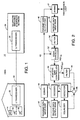
- FIG. 1 shows an overall block diagram of one data communications environment, i.e., the integrated services digital network (ISDN) 10, to which the present invention may be applied.
- a building 12 may for example include telephone subscribers (16 and 18) and data subscribers (personal computer 14) linked over a local area network to a U-transceiver 20 via an S-transceiver (not shown).
- the U-transceiver 20 is connected by a two-wire "loop" transmission line 22 to another U-transceiver 26 at telephone switching and services network 24 which provides digital switching and other messaging/call processing services.
- One of the important functions that must be performed by U-transceivers 20 and 26 is the accurate detection of symbols transmitted over transmission line 22 which in part depends on accurate and unbiased adjustment of the adaptive gain value applied to received symbols.
- the present invention is described hereafter in the context of an ISDN network that uses U-transceivers, 2B1Q line codes, and the 120 symbol frame format (9 symbol sync field and 111 symbol data field) described above in the background section.
- the present invention may be applied to other types of data communications networks, other types of line codes/symbols, and other digital communication protocols.
- a U-transceiver 40 is shown in function block form in Figure 2 and includes a transmit data input port 42 connected to a coder 44 such as a 2B1Q coder for encoding the binary data pairs into a corresponding quaternary symbol.
- the output of coder 44 is connected to an echo canceler 52 and a transmit data output port 46.
- the transmitted symbols are connected to the transmission loop through a conventional hybrid 47.
- a receive data input port 48 receives symbols transmitted over the transmission loop as well as the echo of symbols transmitted from the transmit data output port 46 via the hybrid 47.
- the output from the receive data input port 48 is filtered in a receive filter 50 with the filtered signals being input to echo canceler 52.
- the receive filter 50 is designed to improve receiving conditions including "shortening the tail" of the received pulse waveform.
- the just transmitted symbol sequence output from the coder 44 output is used to cancel echoes of the just transmitted symbol sequence mixed in with the received symbol sequence in a conventional echo canceler 52.
- the output of echo canceler 52 (AGC in ) is processed by adaptive gain controller 54.
- Adaptive gain controller 54 feeds an AGC output signal AGC out to filter 56.
- the AGC output signal represents (at least in theory) the symbol amplitude adjusted to a desired magnitude value appropriate for a subsequently received symbol.
- Filter 56 essentially suppresses the "precursor" portion of the received, gain adjusted pulse as will be appreciated by those skilled in the art.
- the output of filter 56 is combined in a differencer 58 with the output of an equalizer 66.
- Equalizer 66 essentially models the "post cursor tail" of the received symbol.
- the differencer output is essentially the received symbol which is then identified by detector 60 (as a +1, -1, +3, or -3) as well as fedback to adaptive gain controller 54.
- the detected symbol is decoded in decoder 62 into binary bits and transmitted to a receive data output port 64.
- U-type (and other) transceivers relate to accurate adaptive gain control (AGC) and applications that use AGC. Therefore, the following description focuses on the operation of adaptive gain controller 54.
- AGC adaptive gain control
- the adaptive gain controller 54 output AGC gain affects significantly symbol detection and transceiver synchronization operations.
- accurate and unbiased AGC adjustment is an important part of successful high speed data communications.
- the AGC 54 may be located in other sections of the transceiver including for instance in an analog front end to improve the dynamic range of an analog to digital converter.
- the AGC 54 may also be embodied in a digital signal processor.
- Figure 3 is function block diagram of the adaptive gain controller 54 of transceiver 40 that may be used in implementing the present invention.
- the filtered (in precursor filter 56) and equalized (in equalizer 66) received symbol ready for identification/detection by detector 60 is also fed back to an absolute value detection element 70 in adaptive gain controller 54 to determine the magnitude of the symbol.
- a 2B1Q line code is assumed including symbols corresponding to +1, -1, +3, -3.
- the magnitude of the detected symbol is compared to "1" and "3" thresholds in a threshold comparison unit 72.
- the symbol magnitude is compared to determine whether it is (1) less than 1, (2) greater than 3, or (3) greater than or equal to 1 and less than or equal to 3.
- the threshold comparison unit 72 If the symbol magnitude is greater than or equal to 1 and less than or equal to 3, the threshold comparison unit 72 outputs a hold signal (H) which means that the adaptive gain control value is neither increased nor decreased. If the symbol magnitude is less than 1 (the gain needs to be increased to bring the symbol magnitude up to the desired symbol 1 magnitude recognized by the symbol detector), the threshold comparison unit 72 outputs an increase signal (I). Finally, if the symbol magnitude is greater than 3 (the gain needs to be decreased to bring the symbol magnitude down to the desired symbol 3 magnitude recognized by the symbol detector), threshold comparison element 72 outputs a decrease signal (D).
- H hold signal
- step control unit 74 Depending upon which of the threshold comparison signals received H, I, or D, step control unit 74 generates an appropriate gain adjustment to gain update unit 76 which outputs an AGC gain signal to multiplier 78.
- the AGC adjustment factor is used to adjust, if necessary, the current gain value AGC gain applied to received symbols.
- the output AGC out signal is the received symbol with its amplitude/magnitude adjusted to a standard symbol magnitude.
- the gain adjustment signal (i.e., the AGC gain signal) is in the form of ⁇ *AGC gain in accordance with the AGC gain adjustment equation (4) described above.
- the adjustment factor could also be simply ( ⁇ ) if the factor is to be added to the current AGC value in accordance with equation (3).
- the AGC gain signal is also fed back to the gain update unit 76 as well as to the step control unit 74.
- the AGC gain value is multiplied in multiplier 78 with an input signal AGC in to provide an AGC out signal.
- Step control circuit 74 maintains different step size values, e.g., ⁇ values, for each of the symbol magnitudes.
- each U-frame includes a pattern of nine symbols used for synchronization all of which have a magnitude of three.
- the synchronization frame favors symbols with the magnitude of 3.
- the 111 data symbols which make up the rest of the 120 symbol U-frame have a symmetric probability distribution, i.e., the symbol distribution for these remaining 111 symbols in the frame is -3, -1, +1, and +3, with equal probability.
- the symbol level may be properly adjusted if adjustment of the AGC gain value reflects the probability of receiving the symbol with a respective magnitude. Since most AGC systems adjust the AGC gain value using a fixed incremental step value or size ⁇ , the present invention is described hereafter in terms of adjusting the step size.
- the step size for decreasing the gain i.e., when the gain is adjusted for a symbol magnitude greater than 3, is smaller than the step size for increasing the gain, i.e., when the gain is adjusted for a symbol magnitude less than 1. Recall that the gain is not adjusted when the symbol magnitude is less or equal to 3 and greater than or equal to 1.
- the different step sizes compensate for the statistics favoring decreasing the AGC value since there is a greater probability of receiving a symbol with magnitude 3 than a symbol with magnitude 1.
- the gain value AGC gain at the output of summer 80 is adjusted in accordance with the following equation (similar to equation (4) above):
- AGC gain Gain Adjustment + AGC gain
- the step size is not fixed but is instead variable and determined in advance in accordance with the known signal distribution of the communications protocol as already described above. For example, if AGC gain is to be decreased, one step size is used, and if AGC gain is to be increased, another step size is to be used.
- the present invention is implemented using digital signal processing techniques. It is desirable in digital signal processing contexts to minimize data processing resources by avoiding high overhead multiplication operations, and instead, to use, if possible, adding/subtracting/shifting operations.
- the calculation of equation (5) requires a multiplication operation every time the gain is updated/adjusted. Therefore, in another preferred example embodiment, the present invention uses (although does not require) an advantageous technique for generating the appropriate step size adjustment factor for adjusting the AGC value that reflects the probability of receiving the symbol with the respective magnitude without requiring a multiplication operation.
- a ratio between the step size ⁇ increase associated with received symbol magnitudes less than 1 and the step size ⁇ decrease associated with received symbol magnitudes greater than 3 should reflect the probability of receiving the symbol with a respective magnitude as follows: Of course, such probability ratios may readily be defined for other types of codes and protocols as well.
- the problem of properly adjusting signal level in the receiving path of a digital communications system is very important because the thresholds necessary for deciding a symbol value are permanently set.
- the present invention provides a novel AGC updating technique which exploits the known symbol distribution of the digital communications protocol to achieve unbiased AGC gain .
- different step sizes/ adjustment factors are determined for increasing and decreasing the AGC value.
- the ratio of the step sizes approximates the ratio of probabilities that the magnitude of the received symbol is a particular magnitude, e.g., a 1 or a 3.
- the present invention is not limited to the example described above using U-transceivers, 2B1Q line codes, and ISDN protocol formats. Rather the present invention may be applied to any known communications protocol to determine and compensate AGC adjustment for any type of symbol bias in any digital communications environment.
- the present invention was described in the context of adaptive gain control, it is equally applicable to adaptive reference control (ARC) techniques where instead of adapting the gain, the decision thresholds are adapted.
- ARC adaptive reference control
Landscapes
- Engineering & Computer Science (AREA)
- Signal Processing (AREA)
- Computer Networks & Wireless Communication (AREA)
- Control Of Amplification And Gain Control (AREA)
- Circuits Of Receivers In General (AREA)
- Dc Digital Transmission (AREA)
- Cable Transmission Systems, Equalization Of Radio And Reduction Of Echo (AREA)
- Telephonic Communication Services (AREA)
Description
- The present invention relates to data communications wherein data symbols are transmitted over a communications channel, and in particular, to an adaptive gain control method and apparatus for adaptively adjusting the amplitude of received symbols.
- Telecommunications systems, such as the integrated data services digital network (ISDN), transmit information over existing telephone lines in coded format. One of several different digital line codes each with a particular symbol distribution may be used to code the binary information. In its simplest form, line coding uses a different signal level to encode each discrete symbol transmitted. While a common form of coding in computer systems is an on/off code using a positive voltage level such as three volts for a binary one and a near zero voltage level for a binary zero, over a transmission link, it is more efficient in terms of power to encode binary data with an equivalent difference in voltage levels but symmetrically balanced about zero volts. For example, in the ISDN, 2-binary, 1-quaternary (2B1Q) line codes are used which employ a four level, pulse amplitude modulation (PAM), nonredundant code. Each pair of binary bits of information to be transmitted is converted to a quaternary symbol (-3, -1, +1, and +3). For example, "00" is coded to a -3, "01" is coded to a -1, "10" is coded to a +3, and "11" is coded to a+1.
- In digital communications environments like the ISDN, digital information is transmitted in accordance with a predetermined protocol or format. Using the ISDN as an example, quaternary, 2B1Q line code symbols are partitioned into frames with each frame containing certain fields of bits including typically at least a synchronization field and a data field. While the information in the data field changes frame-by-frame, the information in the synchronization field includes a specific, predetermined pattern of symbols used by a receiver to synchronize to the transmitter sending the message. For example, in U-transceivers specified for use in the ISDN, each U-frame consists of a field of a 9-quaternary symbol pattern for synchronization and a field of 111 quaternary symbols for data totalling 120 symbols per frame. The nine quaternary symbols in the synchronization field are transmitted in the following pattern (+3, +3, -3, -3, -3, +3, -3, +3, +3).
- Noticeably absent in the synchronization field are quaternary symbols having a magnitude of "1." Thus, unlike the symbol distribution in the data field where symbols -3, -1, +1, and +3 are distributed with equal probability, the synchronization field includes only symbols with a magnitude of "3". Accordingly, the probability (P3) of receiving a symbol with a magnitude of "3" over each frame is
- While in theory, the receiver portion of the U-transceiver is looking for symbols which have amplitude values corresponding to magnitudes of 1 and 3, in reality, distortion on the transmission path, noise, and other factors mean that some of the received symbols have magnitudes different than "1" and others have a magnitude different than "3". Still, the probability (P1/2) that the magnitude of a received signal is less than "1" is the same as the probability that the received signal is greater than "1", e.g., 0.9 and 1.1 are equally probable.
Likewise, the probability (P3/2) that the magnitude of a received signal is less than "3" or greater than "3" is the same, e.g., 3.1 and 2.9. - Adaptive gain control (AGC) is used to adaptively adjust the amplitude level of a received symbol so that its peak sampled amplitude and a corresponding symbol reference amplitude threshold are equal.
U.S. Patent No. 4,251,881 discloses an example of an automatic gain control circuit. This adjustment may be achieved either by adapting the gain in the receive path or by adapting the symbol reference thresholds. It is very important in high speed data communication systems such as the ISDN that the AGC operation be performed accurately so that symbols are properly detected/identified. Typically, the adaptive gain control (AGC) value applied to received symbols is incremented or decremented by some step amount/increment "µ" depending upon the detected symbol magnitude level: - In a steady state system, one could assume that since over time the same number of symbols with magnitude "1" would be received as symbols with magnitude "3", the gain adjustment step size "µ" could be a fixed value to increase or decrease the gain value. However, this assumption is not correct because predetermined symbol patterns in the communications protocol, i.e., the synchronization field in this ISDN example, symbols with magnitude "3" outweigh symbols with magnitude "1". As a result of this statistical unbalance favoring receipt of symbols with magnitude "3", the adaptive gain value is more likely to be decremented than incremented. In other words, the number of times that the received symbol has a magnitude greater than "3" (which requires a decrement or decrease in gain) is larger than the number of times the received symbol has a magnitude less than "1" (which requires an increment or increase in gain) resulting in bias in gain estimate. Such an unbalance adversely affects symbol detection/identification as well as the signal-to-noise ratio of the received symbol and transceiver synchronization operations.
- None of the conventional approaches for updating the AGC value, e.g., see equations (3) and (4), takes into account the statistics of the applied line code which often reveal a biased AGC value. Accordingly, there is a need for an improved AGC approach that compensates for non-symmetric, probabilistic distribution of symbols.
- It is an object of the present invention to provide an adaptive gain control method and apparatus that accurately adjusts the adaptive gain control value applied to received symbols. It is a further object to provide an adaptive gain control method and apparatus that compensates for received symbol unbalance when adjusting gain to achieve an unbiased adaptive gain control value. It is a still further object to provide an improved AGC that compensates for non-symmetric, probabilistic distribution of symbols.
- The present invention satisfies these and other objects as well as overcomes the shortcomings of other adaptive gain control techniques by taking advantage of a known symbol distribution, such as a digital signalling protocol, frame format, etc., to achieve an accurate, unbiased adjustment to an adaptive gain applied to received symbols. Thus, adaptive gain control updating in accordance with the present invention employs one or more different step sizes for incrementing and decrementing the value of the adaptive gain control value depending on the magnitude of the symbol received.
- Initially, a probability of receiving each of a plurality of symbols to be transmitted over a data communications channel is determined for the predetermined communications protocol used over that data communications channel. Based on the probability determined for each symbol, a gain adjustment factor is established for one or more of those symbols. When communication commences, symbols transmitted over the data communications channel are detected, and a gain value is selectively adjusted using an adjustment factor established for the currently detected symbol.
- If the communications system includes a set of symbols having two different magnitudes, and assuming a first symbol magnitude has an associated probability greater than a probability of occurrence associated with a second symbol magnitude (based on the communications protocol), the adjustment factor established for the first symbol is smaller than the adjustment factor established for the second symbol. Thereafter, when a symbol is detected, its magnitude is determined, and the magnitude is compared to various symbol magnitude threshold levels. If the received symbol magnitude is within a predetermined threshold range, the current adaptive gain value is not adjusted. On the other hand, if the received symbol magnitude is outside of that predetermined range, the gain value is varied based on the adjustment factor determined specifically for that symbol's magnitude.
- According to the present invention, the AGC gain value is varied using adjustment factors based on symbol magnitude receipt probabilities determined from the known distribution of plural symbols transmitted over the communications path. In this way, the present invention compensates for bias favoring one or more of the symbols thereby achieving more accurate and reliable symbol detection.
- A better understanding of the features and advantages of the present invention will be obtained by reference to the following detailed description of the invention and the accompanying drawings which set forth example embodiments in which the principles of the present invention are utilized. The scope of the invention is defined by the appended claims.
-
- FIGURE 1 is a system level drawing showing an integrated services data network (ISDN) which is one example environment in which the present invention may be applied;
- FIGURE 2 is a functional block diagram of an example transceiver employing an adaptive gain controller in accordance with an example embodiment of the present invention;
- FIGURE 3 is a function block diagram of an adaptive gain controller in accordance with an example embodiment of the present invention; and
- FIGURE 4 is a function block diagram relating specifically to step control and gain update elements of the adaptive gain controller illustrated in Figure 3.
-
- In the following description, for purposes of explanation and not limitation, specific details are set forth, such as particular circuits, interfaces, techniques, etc. in order to provide a thorough understanding of the present invention. However, it will be apparent to one skilled in the art that the present invention may be practiced in other embodiments that depart from these specific details.
In other instances, detailed descriptions of well known methods, devices, and circuits are omitted so as not to obscure the description of the present invention with unnecessary detail. - Figure 1 shows an overall block diagram of one data communications environment, i.e., the integrated services digital network (ISDN) 10, to which the present invention may be applied. A building 12 may for example include telephone subscribers (16 and 18) and data subscribers (personal computer 14) linked over a local area network to a
U-transceiver 20 via an S-transceiver (not shown). The U-transceiver 20 is connected by a two-wire "loop"transmission line 22 to another U-transceiver 26 at telephone switching andservices network 24 which provides digital switching and other messaging/call processing services. One of the important functions that must be performed byU-transceivers transmission line 22 which in part depends on accurate and unbiased adjustment of the adaptive gain value applied to received symbols. - For purposes of illustration and description only, the present invention is described hereafter in the context of an ISDN network that uses U-transceivers, 2B1Q line codes, and the 120 symbol frame format (9 symbol sync field and 111 symbol data field) described above in the background section. However, as will be appreciated by those skilled in the art, the present invention may be applied to other types of data communications networks, other types of line codes/symbols, and other digital communication protocols.
- A U-transceiver 40 is shown in function block form in Figure 2 and includes a transmit
data input port 42 connected to acoder 44 such as a 2B1Q coder for encoding the binary data pairs into a corresponding quaternary symbol. The output ofcoder 44 is connected to anecho canceler 52 and a transmitdata output port 46. The transmitted symbols are connected to the transmission loop through aconventional hybrid 47. A receivedata input port 48 receives symbols transmitted over the transmission loop as well as the echo of symbols transmitted from the transmitdata output port 46 via thehybrid 47. The output from the receivedata input port 48 is filtered in a receivefilter 50 with the filtered signals being input to echocanceler 52. The receivefilter 50 is designed to improve receiving conditions including "shortening the tail" of the received pulse waveform. - The just transmitted symbol sequence output from the
coder 44 output is used to cancel echoes of the just transmitted symbol sequence mixed in with the received symbol sequence in aconventional echo canceler 52. The output of echo canceler 52 (AGCin) is processed byadaptive gain controller 54.Adaptive gain controller 54 feeds an AGC output signal AGCout to filter 56. After appropriately adjusting the gain, the AGC output signal represents (at least in theory) the symbol amplitude adjusted to a desired magnitude value appropriate for a subsequently received symbol.Filter 56 essentially suppresses the "precursor" portion of the received, gain adjusted pulse as will be appreciated by those skilled in the art. The output offilter 56 is combined in adifferencer 58 with the output of anequalizer 66.Equalizer 66 essentially models the "post cursor tail" of the received symbol. As a result, the differencer output is essentially the received symbol which is then identified by detector 60 (as a +1, -1, +3, or -3) as well as fedback toadaptive gain controller 54. The detected symbol is decoded indecoder 62 into binary bits and transmitted to a receivedata output port 64. - The detailed timing and operation of U-type (and other) transceivers are generally known and are not necessary for an understanding of the present invention which relates to accurate adaptive gain control (AGC) and applications that use AGC. Therefore, the following description focuses on the operation of
adaptive gain controller 54. However, from the general description oftransceiver 40 provided above, one skilled in the art can readily appreciate that theadaptive gain controller 54 output AGCgain affects significantly symbol detection and transceiver synchronization operations. Clearly, accurate and unbiased AGC adjustment is an important part of successful high speed data communications. Those skilled in the art will also appreciate that theAGC 54 may be located in other sections of the transceiver including for instance in an analog front end to improve the dynamic range of an analog to digital converter. TheAGC 54 may also be embodied in a digital signal processor. - Figure 3 is function block diagram of the
adaptive gain controller 54 oftransceiver 40 that may be used in implementing the present invention. The filtered (in precursor filter 56) and equalized (in equalizer 66) received symbol ready for identification/detection bydetector 60 is also fed back to an absolutevalue detection element 70 inadaptive gain controller 54 to determine the magnitude of the symbol. Again, a 2B1Q line code is assumed including symbols corresponding to +1, -1, +3, -3. The magnitude of the detected symbol is compared to "1" and "3" thresholds in athreshold comparison unit 72. The symbol magnitude is compared to determine whether it is (1) less than 1, (2) greater than 3, or (3) greater than or equal to 1 and less than or equal to 3. If the symbol magnitude is greater than or equal to 1 and less than or equal to 3, thethreshold comparison unit 72 outputs a hold signal (H) which means that the adaptive gain control value is neither increased nor decreased. If the symbol magnitude is less than 1 (the gain needs to be increased to bring the symbol magnitude up to the desired symbol 1 magnitude recognized by the symbol detector), thethreshold comparison unit 72 outputs an increase signal (I). Finally, if the symbol magnitude is greater than 3 (the gain needs to be decreased to bring the symbol magnitude down to the desired symbol 3 magnitude recognized by the symbol detector),threshold comparison element 72 outputs a decrease signal (D). - Depending upon which of the threshold comparison signals received H, I, or D,
step control unit 74 generates an appropriate gain adjustment to gainupdate unit 76 which outputs an AGCgain signal tomultiplier 78. The AGC adjustment factor is used to adjust, if necessary, the current gain value AGCgain applied to received symbols. The output AGCout signal is the received symbol with its amplitude/magnitude adjusted to a standard symbol magnitude. - In the example embodiment shown in Fig. 3, the gain adjustment signal (i.e., the AGCgain signal) is in the form of ±µ*AGCgain in accordance with the AGC gain adjustment equation (4) described above. Of course, the adjustment factor could also be simply (±µ) if the factor is to be added to the current AGC value in accordance with equation (3). The AGCgain signal is also fed back to the
gain update unit 76 as well as to thestep control unit 74. The AGCgain value is multiplied inmultiplier 78 with an input signal AGCin to provide an AGCout signal. -
Step control circuit 74 maintains different step size values, e.g., µ values, for each of the symbol magnitudes. In our example case adopting a 2B1Q line code and a standard ISDN data communications protocol, each U-frame includes a pattern of nine symbols used for synchronization all of which have a magnitude of three. Thus, the synchronization frame favors symbols with the magnitude of 3. The 111 data symbols which make up the rest of the 120 symbol U-frame have a symmetric probability distribution, i.e., the symbol distribution for these remaining 111 symbols in the frame is -3, -1, +1, and +3, with equal probability. On the whole then, and as described in detail in the Background section, the probability of receiving symbols with magnitude 3 is equal to P3 = 0.5375 and symbols with magnitude 1 is equal to P1 = 0.4625. - Despite this non-symmetrical probability distribution, the symbol level may be properly adjusted if adjustment of the AGCgain value reflects the probability of receiving the symbol with a respective magnitude. Since most AGC systems adjust the AGCgain value using a fixed incremental step value or size µ, the present invention is described hereafter in terms of adjusting the step size. The step size for decreasing the gain, i.e., when the gain is adjusted for a symbol magnitude greater than 3, is smaller than the step size for increasing the gain, i.e., when the gain is adjusted for a symbol magnitude less than 1. Recall that the gain is not adjusted when the symbol magnitude is less or equal to 3 and greater than or equal to 1. The different step sizes compensate for the statistics favoring decreasing the AGC value since there is a greater probability of receiving a symbol with magnitude 3 than a symbol with magnitude 1.
- There are a number of different techniques for implementing these two different step sizes (gain adjustment factors) to adjust the AGCgain value without bias. For example, the output signals (D, I, H) of the
threshold comparison unit 72 may be used by thestep control unit 74 to select the appropriate gain step size µ previously determined for each symbol magnitude based on the known signal distribution/protocol used in the data transmission system, i.e., step sizes for decreasing (µdecrease) and increasing (µincrease) the current gain value. Then, based on the threshold output comparison, thestep controller 74 generates the appropriate "Gain Adjustment" signal in accordance with the following: - Thus, the gain value AGCgain at the output of
summer 80 is adjusted in accordance with the following equation (similar to equation (4) above): - Preferably (although not necessarily), the present invention is implemented using digital signal processing techniques. It is desirable in digital signal processing contexts to minimize data processing resources by avoiding high overhead multiplication operations, and instead, to use, if possible, adding/subtracting/shifting operations. The calculation of equation (5) requires a multiplication operation every time the gain is updated/adjusted. Therefore, in another preferred example embodiment, the present invention uses (although does not require) an advantageous technique for generating the appropriate step size adjustment factor for adjusting the AGC value that reflects the probability of receiving the symbol with the respective magnitude without requiring a multiplication operation.
- A ratio between the step size µincrease associated with received symbol magnitudes less than 1 and the step size µdecrease associated with received symbol magnitudes greater than 3 should reflect the probability of receiving the symbol with a respective magnitude as follows:Of course, such probability ratios may readily be defined for other types of codes and protocols as well.

- Mathematically, µincrease can be represented as incrementing step size µ modified by an exponential factor of 2 such as
j=2 j=3 j=4 j=5 j=6 ... j=∞ i=2 1.6667 1.4286 1.3333 1.2903 1.2698 ... 1.25 i=3 1.5000 1.2857 1.2000 1.1613 1.1429 ... 1.125 i=4 1.4167 1.2143 1.1333 1.0968 1.0794 ... 1.0625 i=5 1.3750 1.1786 1.1000 1.0645 1.0476 ... 1.0313 i=6 1.3542 1.1607 1.0833 1.0484 1.0317 ... 1.0156 ... ... ... ... ... ... ... ... i=∞ 1.3333 1.1429 1.0667 1.0323 1.0159 ... 1.0 - By representing in a binary context the ratio of µincrease and µdecrease as (1+2-i)/(1-2-j),
multiplication in equation (5) can be replaced with a shift and an add which conserves data processing resources. As an example, assume the AGC gain is to be multiplied by an adjustment of µ = 2-14. This multiplication operation corresponds in a binary digital processing environment to shifting thecurrent gain 14 binary bit positions. Similarly, µincrease = 2-14 + 2-17 (where 2-17 is the step size adjustment factor) corresponds to two shifts and one addition. First, the gain (or other number which would otherwise have been multiplied by µ increase) is shifted by fourteen binary bit positions and then added to the gain shifted an additional three binary positions. Mathematically, this is equivalent tostep control 74 in a figure 4, adding it to itself, and shifting theresult 14 binary positions. This latter operation is useful to determine the values of µincrease and µdecrease. Namely, if - By calculating the ratio of step sizes, a best choice of exponents i and j can be made. As shown below in equation (12), selecting both i and j as 3 is not quite close enough to 1.162.
(1+2-3)/(1-2-5) of 1.1613 most closely approximates the 2B1Q line code probability ratio. In an AGC implementation where the AGC adjustment is only to be corrected for incrementing, i.e., decrementing occurs using the standard step size µ, the probability ratio P3/P1 is most closely approximated by (1 + 2-3). Similarly, when the AGC adjustment is only to be corrected for decrementing, using the standard step size µ for incrementing, the probability ratio P3/P1 is most closely approximated by (1-2-3). - As discussed in the background, the problem of properly adjusting signal level in the receiving path of a digital communications system is very important because the thresholds necessary for deciding a symbol value are permanently set. The present invention provides a novel AGC updating technique which exploits the known symbol distribution of the digital communications protocol to achieve unbiased AGCgain. In general, different step sizes/ adjustment factors are determined for increasing and decreasing the AGC value. In a symbol set that uses two symbol magnitudes like the 2B1Q line code, the ratio of the step sizes approximates the ratio of probabilities that the magnitude of the received symbol is a particular magnitude, e.g., a 1 or a 3. The detailed example implementation described above in conjunction with Table 1 provides a practical implementation which uses a binary approximation of the probability ratio requiring only a small number of low power digital processing computations. This latter feature is particularly advantageous because it can be used with transceivers in high speed data communications systems that are manufactured using lower cost, lower power VLSI circuitry, where the cost and power are in part a function of the number computations to update the AGC value.
- While the invention has been described in connection with what is presently considered to be the most practical and preferred embodiment, it is to be understood that the invention is not to be limited to the disclosed embodiment, but on the contrary, is intended to cover various modifications and equivalent arrangements included within the scope of the appended claims. For example, the present invention is not limited to the example described above using U-transceivers, 2B1Q line codes, and ISDN protocol formats. Rather the present invention may be applied to any known communications protocol to determine and compensate AGC adjustment for any type of symbol bias in any digital communications environment. Although the present invention was described in the context of adaptive gain control, it is equally applicable to adaptive reference control (ARC) techniques where instead of adapting the gain, the decision thresholds are adapted.
Claims (25)
- A method of automatically controlling a gain applied to received symbols transmitted over a data communications channel in a data communications system, comprising the steps of:characterized by the step of automatically varying the gain based on the comparing step and on a known distribution of the symbols to be transmitted over the data communications channel.receiving a symbol, andcomparing a magnitude of the received symbol with a threshold,
- The method in claim 1, wherein the known distribution is based on a probability of each symbol being transmitted over the data communications channel.
- The method in claim 1, wherein the known distribution is based on a probability of each symbol being transmitted over the data communications channel for a given communications protocol.
- The method in claim 1, wherein the symbols to be transmitted over the data communications channel include a first symbol having a first symbol magnitude and a second symbol having a second symbol magnitude, and the method further includes incrementing the gain using a first step size associated with a first probability corresponding to the first symbol magnitude or decrementing the gain using a second different step size associated with a second probability corresponding to the second symbol magnitude.
- The method in claim 4, wherein a difference in the first and second step sizes compensates for varying the gain in favor of one of the first and second symbol magnitudes due to the known distribution of the symbols to be transmitted over the data communications channel.
- The method in claim 4, wherein a first symbol having a first magnitude is statistically determined as less likely to be detected than a second symbol having a second magnitude, and as a result of the statistical determination, the first step size is greater than the second step size.
- The method in claim 1, wherein the symbols to be transmitted over the communications channel include a first symbol having a first symbol magnitude and a second symbol having a second symbol magnitude, and wherein selective application of a first gain adjustment value and a second gain adjustment value compensates for varying the gain in favor of one of the first and second symbol magnitudes due to the known distribution of the symbols to be transmitted over the data communications channel.
- The method in claim 7, wherein the first symbol having the first symbol magnitude is statistically determined as less likely to be detected than the second symbol having the second symbol magnitude, and as a result of the statistical determination, the first gain adjustment value is greater than the second gain adjustment value.
- The method in claim 1, wherein the comparing step comprises the steps of:determining whether a magnitude of a received symbol is within a predetermined range;if the received symbol magnitude is within the predetermined range, maintaining the gain at a current gain value; andif the received symbol magnitude is outside of the predetermined range, performing the automatically varying step.
- The method in claim 1, wherein the symbols are transmitted over the data communications channel using a predetermined communications protocol, further comprising:determining for the predetermined communications protocol, a probability of transmitting certain symbol magnitudes over the data communications channel;establishing an adjustment factor for each symbol magnitude to be transmitted over the data communications channel based on the probability of transmitting each symbol magnitude;receiving a symbol transmitted over the data communications channel; andselectively adjusting a gain value applied to the received symbol using the adjustment factor established for the magnitude of the symbol received.
- The method in claim 10, wherein a first symbol magnitude has an associated probability of being transmitted over the data communications channel greater than an associated probability of a second symbol magnitude being transmitted over the data communications channel, and wherein the adjustment factor established for the first symbol magnitude is smaller that the adjustment factor established for the second symbol magnitude.
- The method in claim 10, wherein the receiving step further comprises the steps of:determining a magnitude of the received symbol, andcomparing the determined symbol magnitude to one or more thresholds to determine whether the gain value should be adjusted, and if so, whether to increase or decrease the gain value.
- The method in claim 10, wherein the gain value is adjusted in accordance with the following:
- The method in claim 10, further comprising:
representing the gain value as a binary number, wherein the gain value is adjusted by shifting the binary number gain value by a number of bit shifts corresponding to at least one adjustment factor. - The method in claim 14, further comprising:
approximating a number of bit shifts for each symbol magnitude using a predetermined relationship of the probability of transmitting each symbol magnitude. - The method according to claim 15, wherein the relationship is the ratio of a probability µ1 of receiving the first symbol magnitude for increasing the gain value over a probability µ2 of receiving the second symbol magnitude for decreasing the gain value, the ratio of µ1/µ2 being approximated by (1+2-i)/(1-2-j), i and j being integers.
- The method in claim 1, further comprising the steps of:determining for a predetermined digital communications protocol used to transmit symbols over the data communications channel, an error in adjusting a gain value applied to received symbols, wherein a first symbol or series of symbols is predictably received over the data communications channel more frequently than a second symbol or series of symbols;determining a variable adjustment factor that compensates for the error; andadjusting a gain applied to received symbols using the variable adjustment factor.
- The method in claim 17, wherein the digital communications protocol is a framed protocol with at least some frames having at least one field which includes a greater number of first symbol or series of symbols than a second symbol or series of symbols such that there is a greater probability of receiving the first symbol or series of symbols.
- The method in claim 17, wherein a first adjustment factor corresponding to the first symbol or series of symbols is smaller than a second adjustment factor corresponding to the second symbol or series of symbols.
- An adaptive gain controller (54) for selectively adjusting a gain applied to a symbol received by the adaptive gain controller, the adaptive gain controller comprising:characterized in that the adaptive gain controller further comprises:a magnitude detector (70) for determining the magnitude of a received symbol;a comparator (72) performing a threshold comparison on the symbol magnitude;
a controller (74) receiving an output from the comparator, and based on a known symbol distribution of the symbols to be transmitted, selectively maintaining the gain at the current value, increasing the gain by a first amount, or decreasing the gain by a second different amount. - The adaptive gain controller according to claim 20, wherein gain is represented in binary format and the controller includes:a first shift register (86) for shifting the binary gain value a predetermined number of shift positions corresponding to the second amount to produce a first shifted signal;a second shift register (84) for shifting the first shifted signal by another predetermined number of shift positions corresponding to the first amount to produce a second shifted signal; anda multiplexer (90) having three inputs receiving the first shifted signal, the second shifted signal, and a null input, wherein one of the three inputs is selected in accordance with the output from the comparator (72).
- The adaptive gain controller according to claim 20, wherein the first and second amounts are determined based on a probability of each symbol being received during a predetermined time period.
- The adaptive gain controller according to claim 20, wherein the first and second amounts are determined based on a probability of each symbol being received for a given communications protocol.
- The adaptive gain controller according to claim 20, wherein the first and second amounts values compensate for a bias in varying the gain in favor of one of the first and second symbols due to the known distribution of the symbols to be received by the adaptive gain controller.
- An adaptive gain controller in claim 20, further comprising:means (72) for determining whether a magnitude of a received symbol is within a predetermined range;means (90) for maintaining the gain at a current gain value if the received symbol magnitude is within the predetermined range; andmeans (90) for automatically varying the gain based on a known distribution of the symbols to be received by the adaptive gain controller if the received symbol magnitude is outside of the predetermined range.
Applications Claiming Priority (3)
| Application Number | Priority Date | Filing Date | Title |
|---|---|---|---|
| US497228 | 1983-05-23 | ||
| US08/497,228 US5727031A (en) | 1995-06-30 | 1995-06-30 | Adaptive gain controller |
| PCT/SE1996/000868 WO1997002656A1 (en) | 1995-06-30 | 1996-06-28 | Adaptive gain controller |
Publications (2)
| Publication Number | Publication Date |
|---|---|
| EP0835552A1 EP0835552A1 (en) | 1998-04-15 |
| EP0835552B1 true EP0835552B1 (en) | 2001-11-21 |
Family
ID=23975986
Family Applications (1)
| Application Number | Title | Priority Date | Filing Date |
|---|---|---|---|
| EP96922354A Expired - Lifetime EP0835552B1 (en) | 1995-06-30 | 1996-06-28 | Adaptive gain controller |
Country Status (7)
| Country | Link |
|---|---|
| US (1) | US5727031A (en) |
| EP (1) | EP0835552B1 (en) |
| JP (1) | JPH11514169A (en) |
| CN (1) | CN1193424A (en) |
| AU (1) | AU714227B2 (en) |
| DE (1) | DE69617241T2 (en) |
| WO (1) | WO1997002656A1 (en) |
Families Citing this family (11)
| Publication number | Priority date | Publication date | Assignee | Title |
|---|---|---|---|---|
| US6208873B1 (en) * | 1998-11-23 | 2001-03-27 | Qualcomm Incorporated | Method and apparatus for transmitting reverse link power control signals based on the probability that the power control command is in error |
| US6654594B1 (en) * | 2000-05-30 | 2003-11-25 | Motorola, Inc. | Digitized automatic gain control system and methods for a controlled gain receiver |
| DE602004027046D1 (en) * | 2003-07-14 | 2010-06-17 | Ericsson Telefon Ab L M | METHOD AND DEVICE FOR THE AUTOMATIC GAIN CONTROL OF A WIRELESS RECEIVER |
| CN100361400C (en) * | 2003-10-28 | 2008-01-09 | 华为技术有限公司 | A method for automatic gain control of a radio frequency receiving channel |
| US7539614B2 (en) * | 2003-11-14 | 2009-05-26 | Nxp B.V. | System and method for audio signal processing using different gain factors for voiced and unvoiced phonemes |
| US7668053B2 (en) * | 2005-06-03 | 2010-02-23 | Zoran Corporation | Processing an information carrying signal |
| JP4285506B2 (en) * | 2006-07-07 | 2009-06-24 | ヤマハ株式会社 | Auto gain control circuit |
| US20120161989A1 (en) * | 2010-12-27 | 2012-06-28 | South Daniel E | Exponential line coding |
| CN102684620A (en) * | 2011-03-16 | 2012-09-19 | 十速科技股份有限公司 | Piecewise linear gain method |
| CN112671351B (en) * | 2020-12-17 | 2023-12-15 | 深圳市国微电子有限公司 | Analog front-end circuit applied to gigabit Ethernet receiver system |
| CN114039617B (en) * | 2021-11-01 | 2022-12-02 | 国芯科技(广州)有限公司 | Automatic gain control method for wireless communication radio frequency receiver |
Family Cites Families (21)
| Publication number | Priority date | Publication date | Assignee | Title |
|---|---|---|---|---|
| US3562504A (en) * | 1967-11-08 | 1971-02-09 | Texas Instruments Inc | Digital automatic gain control |
| US4207523A (en) * | 1977-09-01 | 1980-06-10 | Honeywell Inc. | Digital channel on-line pseudo error dispersion monitor |
| US4161628A (en) * | 1978-01-31 | 1979-07-17 | Harris Corporation | Technique for tracking amplitude fades for multi-amplitude signalling |
| US4251881A (en) * | 1978-06-05 | 1981-02-17 | Storage Technology Corporation | Centralized automatic gain control circuit |
| GB8322440D0 (en) * | 1983-08-19 | 1983-09-21 | Gen Electric Co Plc | Frequency division multiplex transmission equipment |
| US4623934A (en) * | 1983-11-16 | 1986-11-18 | Rockwell International Corporation | AGC update apparatus and method of using same |
| US4625240A (en) * | 1984-07-25 | 1986-11-25 | Eeco, Inc. | Adaptive automatic gain control |
| JPH0614627B2 (en) * | 1985-06-04 | 1994-02-23 | 富士通株式会社 | Modem training methods |
| US4683578A (en) * | 1985-07-05 | 1987-07-28 | Paradyne Corporation | Automatic gain control using the extreme points of a constellation |
| JPS62216511A (en) * | 1986-03-18 | 1987-09-24 | Nec Corp | Automatic gain controller |
| US5029182A (en) * | 1988-10-24 | 1991-07-02 | Hughes Aircraft Company | Automatic gain control (AGC) for frequency hopping receiver |
| US4982428A (en) * | 1988-12-29 | 1991-01-01 | At&T Bell Laboratories | Arrangement for canceling interference in transmission systems |
| US4972430A (en) * | 1989-03-06 | 1990-11-20 | Raytheon Company | Spread spectrum signal detector |
| US5023869A (en) * | 1989-03-27 | 1991-06-11 | Alberta Telecommunications Research Centre | Method and apparatus for maximizing the transmission capacity of a multi-channel bidirectional communications link |
| US5233634A (en) * | 1989-10-18 | 1993-08-03 | Nokia Mobile Phones Ltd. | Automatic gain control circuit in a radio telephone receiver |
| US5295178A (en) * | 1990-12-03 | 1994-03-15 | Ericsson Ge Mobile Communications Inc. | Digital signal processor for radio base station |
| JP2744357B2 (en) * | 1991-04-23 | 1998-04-28 | キヤノン株式会社 | Private branch exchange |
| US5208846A (en) * | 1991-09-03 | 1993-05-04 | Tektronix, Inc. | Subscriber loop tester for telephone switching systems |
| US5245556A (en) * | 1992-09-15 | 1993-09-14 | Universal Data Systems, Inc. | Adaptive equalizer method and apparatus |
| US5313172A (en) * | 1992-12-11 | 1994-05-17 | Rockwell International Corporation | Digitally switched gain amplifier for digitally controlled automatic gain control amplifier applications |
| US5517527A (en) * | 1992-12-11 | 1996-05-14 | Industrial Technology Research Institute | Adaptive equalizer for ISDN U-interface transceiver |
-
1995
- 1995-06-30 US US08/497,228 patent/US5727031A/en not_active Expired - Lifetime
-
1996
- 1996-06-28 WO PCT/SE1996/000868 patent/WO1997002656A1/en not_active Ceased
- 1996-06-28 EP EP96922354A patent/EP0835552B1/en not_active Expired - Lifetime
- 1996-06-28 DE DE69617241T patent/DE69617241T2/en not_active Expired - Lifetime
- 1996-06-28 JP JP9505069A patent/JPH11514169A/en not_active Ceased
- 1996-06-28 AU AU63252/96A patent/AU714227B2/en not_active Ceased
- 1996-06-28 CN CN96196385A patent/CN1193424A/en active Pending
Also Published As
| Publication number | Publication date |
|---|---|
| AU6325296A (en) | 1997-02-05 |
| WO1997002656A1 (en) | 1997-01-23 |
| CN1193424A (en) | 1998-09-16 |
| AU714227B2 (en) | 1999-12-23 |
| DE69617241D1 (en) | 2002-01-03 |
| JPH11514169A (en) | 1999-11-30 |
| EP0835552A1 (en) | 1998-04-15 |
| DE69617241T2 (en) | 2002-06-27 |
| US5727031A (en) | 1998-03-10 |
Similar Documents
| Publication | Publication Date | Title |
|---|---|---|
| US5157690A (en) | Adaptive convergent decision feedback equalizer | |
| JP4727303B2 (en) | Mixed-mode adaptive analog reception architecture for data communication | |
| KR960011120B1 (en) | Method and apparatus for generating optimal adaptive filter update coefficients | |
| EP0835552B1 (en) | Adaptive gain controller | |
| CN1151672A (en) | Echo Canceling method and apparatus for data over cellular | |
| JP3679809B2 (en) | Method and apparatus for reducing errors in received communication signals | |
| EP0187778A1 (en) | Adaptive hybrid circuit. | |
| CN1138787A (en) | Modem receiver pre-emphasis | |
| CN1475056A (en) | Automatic Gain Control for Time Division Duplex Receivers | |
| KR100422102B1 (en) | Method and device for estimating downstream echo in a communication network | |
| US6570916B1 (en) | Adaptive equalization circuit and method | |
| KR100416888B1 (en) | System, device and method for pcm upstream transmission utilizing an optimized transmit constellation | |
| US7227891B2 (en) | Transceiver employing training-while-working mode | |
| US20040257253A1 (en) | Adaptive decision slicer | |
| US5677934A (en) | Multipath propagation compensation in a TDMA system | |
| US6741644B1 (en) | Pre-emphasis filter and method for ISI cancellation in low-pass channel applications | |
| US6463106B1 (en) | Receiver with adaptive processing | |
| US6047032A (en) | Signal equalization and data recovery with non-linear digital threshold feedback | |
| US6721357B1 (en) | Constellation generation and re-evaluation | |
| US6438156B1 (en) | Stepwise adaptive finite impulse response filter for spread spectrum radio | |
| US6961386B2 (en) | Device and method for increasing the bandwidth in a line-connected multicarrier system | |
| JP2002198869A (en) | Method for estimating impulse response in information transmission channel | |
| US5809046A (en) | Method and a system for fast adjusting data receiving modem | |
| JP3301462B2 (en) | Modulation multi-level information transmission method | |
| KR100323706B1 (en) | Adaptitve decoder using signal-to-noise ratio |
Legal Events
| Date | Code | Title | Description |
|---|---|---|---|
| PUAI | Public reference made under article 153(3) epc to a published international application that has entered the european phase |
Free format text: ORIGINAL CODE: 0009012 |
|
| 17P | Request for examination filed |
Effective date: 19971216 |
|
| AK | Designated contracting states |
Kind code of ref document: A1 Designated state(s): DE FR GB IT SE |
|
| 17Q | First examination report despatched |
Effective date: 20000303 |
|
| GRAG | Despatch of communication of intention to grant |
Free format text: ORIGINAL CODE: EPIDOS AGRA |
|
| GRAG | Despatch of communication of intention to grant |
Free format text: ORIGINAL CODE: EPIDOS AGRA |
|
| GRAH | Despatch of communication of intention to grant a patent |
Free format text: ORIGINAL CODE: EPIDOS IGRA |
|
| GRAH | Despatch of communication of intention to grant a patent |
Free format text: ORIGINAL CODE: EPIDOS IGRA |
|
| GRAA | (expected) grant |
Free format text: ORIGINAL CODE: 0009210 |
|
| AK | Designated contracting states |
Kind code of ref document: B1 Designated state(s): DE FR GB IT SE |
|
| REG | Reference to a national code |
Ref country code: GB Ref legal event code: IF02 |
|
| REF | Corresponds to: |
Ref document number: 69617241 Country of ref document: DE Date of ref document: 20020103 |
|
| ET | Fr: translation filed | ||
| PLBE | No opposition filed within time limit |
Free format text: ORIGINAL CODE: 0009261 |
|
| STAA | Information on the status of an ep patent application or granted ep patent |
Free format text: STATUS: NO OPPOSITION FILED WITHIN TIME LIMIT |
|
| 26N | No opposition filed | ||
| PGFP | Annual fee paid to national office [announced via postgrant information from national office to epo] |
Ref country code: IT Payment date: 20070626 Year of fee payment: 12 |
|
| PGFP | Annual fee paid to national office [announced via postgrant information from national office to epo] |
Ref country code: SE Payment date: 20070627 Year of fee payment: 12 |
|
| EUG | Se: european patent has lapsed | ||
| PG25 | Lapsed in a contracting state [announced via postgrant information from national office to epo] |
Ref country code: IT Free format text: LAPSE BECAUSE OF NON-PAYMENT OF DUE FEES Effective date: 20080628 |
|
| PG25 | Lapsed in a contracting state [announced via postgrant information from national office to epo] |
Ref country code: SE Free format text: LAPSE BECAUSE OF NON-PAYMENT OF DUE FEES Effective date: 20080629 |
|
| PGFP | Annual fee paid to national office [announced via postgrant information from national office to epo] |
Ref country code: DE Payment date: 20130627 Year of fee payment: 18 Ref country code: GB Payment date: 20130627 Year of fee payment: 18 |
|
| PGFP | Annual fee paid to national office [announced via postgrant information from national office to epo] |
Ref country code: FR Payment date: 20130702 Year of fee payment: 18 |
|
| REG | Reference to a national code |
Ref country code: DE Ref legal event code: R119 Ref document number: 69617241 Country of ref document: DE |
|
| GBPC | Gb: european patent ceased through non-payment of renewal fee |
Effective date: 20140628 |
|
| REG | Reference to a national code |
Ref country code: FR Ref legal event code: ST Effective date: 20150227 |
|
| PG25 | Lapsed in a contracting state [announced via postgrant information from national office to epo] |
Ref country code: DE Free format text: LAPSE BECAUSE OF NON-PAYMENT OF DUE FEES Effective date: 20150101 |
|
| REG | Reference to a national code |
Ref country code: DE Ref legal event code: R119 Ref document number: 69617241 Country of ref document: DE Effective date: 20150101 |
|
| PG25 | Lapsed in a contracting state [announced via postgrant information from national office to epo] |
Ref country code: GB Free format text: LAPSE BECAUSE OF NON-PAYMENT OF DUE FEES Effective date: 20140628 Ref country code: FR Free format text: LAPSE BECAUSE OF NON-PAYMENT OF DUE FEES Effective date: 20140630 |