EP0834837A2 - Bildverarbeitungsgerät und -verfahren - Google Patents
Bildverarbeitungsgerät und -verfahren Download PDFInfo
- Publication number
- EP0834837A2 EP0834837A2 EP97307872A EP97307872A EP0834837A2 EP 0834837 A2 EP0834837 A2 EP 0834837A2 EP 97307872 A EP97307872 A EP 97307872A EP 97307872 A EP97307872 A EP 97307872A EP 0834837 A2 EP0834837 A2 EP 0834837A2
- Authority
- EP
- European Patent Office
- Prior art keywords
- nongeometric
- expression data
- virtual space
- model
- geometric
- Prior art date
- Legal status (The legal status is an assumption and is not a legal conclusion. Google has not performed a legal analysis and makes no representation as to the accuracy of the status listed.)
- Granted
Links
Images



Classifications
-
- G—PHYSICS
- G06—COMPUTING OR CALCULATING; COUNTING
- G06T—IMAGE DATA PROCESSING OR GENERATION, IN GENERAL
- G06T17/00—Three-dimensional [3D] modelling for computer graphics
Definitions
- the present invention relates to an image processing method and apparatus and a storage medium for generating a virtual environment which can be experienced by the operator.
- the shape data of an object having a very complex shape can hardly be generated or reproduced. It is also hard to acquire shape data of an object having a complex shape from a real object using a three-dimensional measuring device. For this reason, the complex object can hardly be expressed. Particularly, it is more difficult to reproduce a real object having a certain complex shape or complex surface pattern/reflection characteristics (absorption/transmission characteristics). More exactly speaking, generally, a natural object can hardly be expressed although an artificial object can easily be expressed. However, a simple and artificial three-dimensional scene mainly constituted by planes, e.g., a room or a row of buildings can be relatively easily expressed using a relatively small quantity of data.
- Prior arts (1) and (2) are incompatible so the object expressed using nongeometric model data cannot be used in the virtual space generated by prior art (1). This is because although prior art (2) solves the problems of prior art (1), prior art (2) cannot be used to realize a virtual environment.
- an image processing method comprising:
- an image processing apparatus comprising:
- a computer-readable storage medium which stores a computer program for realizing an image processing method comprising:
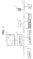
- Fig. 1 is a block diagram of the first embodiment.
- a CPU 1 executes the processing procedure of the first embodiment.
- a processing procedure memory device 2 stores the processing procedure.
- the processing procedure may be stored in the processing procedure memory device 2 in advance, or stored in a storage medium such as an FD, a CD-ROM, a ROM, or a magnetic tape and supplied through an external device interface 8.
- a data memory device 3 holds data generated or input before/after processing and during processing.
- a frame buffer 4 stores image data for presenting the processing process or processing result, which is to be sent to a display device.
- a window system 5 of the image processing apparatus displays image data stored in the frame buffer 4.
- a keyboard 6 is used to input an instruction in the processing process.
- a mouse 7 is a pointing device for designating a position on the screen.
- the external device interface 8 is used to input/output data or processing procedure.
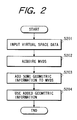
- Fig. 2 is a flow chart showing the processing flow of the first embodiment.
- the first embodiment will be described in detail with reference to Fig. 2.
- step S201 virtual space data using a geometric model for forming a virtual environment is input.
- a modeler device capable of generating some computer graphics geometric data and surface characteristic data.
- a geometric model and surface characteristic data may be generated in step S201, or data generated in another processing may be loaded.
- the geometric data means polygon data such as a triangular patch or free surface data such as NURBS.
- the surface characteristic data represent the material, reflection characteristics, and pattern of the object.
- the pattern is input as texture data.
- the texture data represents the surface pattern of polygon data or free surface data.
- the texture data describes the correspondence between pattern image data and a target object to which the image data is to be pasted.
- MVDS Multi-Viewpoint Data System
- the target object is expressed by describing the "appearance" of the object without estimating or measuring the shape of the object.
- the basic concept of this method will be described below.
- the geometric model describes the target object by recording the shape information of the target object.
- the MVDS describes the target object by recording data for reconstructing various "appearances" without reconstructing or measuring the shape of the target object. More specifically, a number of images are photographed around the target object, and the appearance of the target object is described on the basis of the images. Observation need not be performed in correspondence with all viewpoints necessary in reconstructing the appearance on the basis of the description data. It is considered that the reconstructed image can be generated from a certain limited amount of observation data.
- the MVDS means data converted from such finite multi-viewpoint observation data to readily generate an image viewed from various viewpoints.
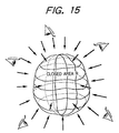
- the MVDS is acquired by recording a number of data (light emerging from an area) which can be observed as an image from an assumed area where the target object supposedly exists. For this reason, in the MVDS, a space (area where light emerges; this area will be referred to as a closed area (space) R hereinafter) where the target object is present is explicitly or implicitly assumed, as shown in Fig. 15.
- the camera arrangement in photographing must be known. More specifically, the relative positional relationship between the closed area R and the camera arrangement in photographing is known. In other words, the direction (coordinate axes) of the closed area R and the scaling factor are obtained from the geometric arrangement information of the camera in photographing.
- the geometric arrangement information of the camera is obtained using a photographing device whose movement can be controlled, or determined on the basis of some image characteristic feature of the observed multi-viewpoint image.
- An image at an arbitrary viewpoint is reconstructed from the MVDS on the basis of the position and direction of a virtual camera viewed from the closed area R.
- MVDS light space data to be described below can be used.
- an image which can be observed at a viewpoint P in the three-dimensional space where z > 0 is equivalent to an image obtained by sampling only light beams passing through the viewpoint P from the set of the light beams passing through the reference plane 1101, as shown in Fig. 12.
- each light beam is represented by a position (x,y) through which the light beam passes, angles ⁇ and ⁇ (Fig. 11B) between the light beam and the X- and Y-axes, time t when the light beam has passed through the plane, and the color (r,g,b) of the light beam.
- a position (x,y) through which the light beam passes a position (x,y) through which the light beam passes, angles ⁇ and ⁇ (Fig. 11B) between the light beam and the X- and Y-axes, time t when the light beam has passed through the plane, and the color (r,g,b) of the light beam.
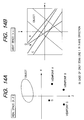
- a light beam passing through the certain point P exhibits a straight locus as shown in Fig. 13.
- straight loci are obtained from an image obtained at a number of viewpoints (e.g., viewpoints A, B, and C), as shown in Figs. 14A and 14B, and assume that the x-u space is filled with this locus group at a high density.
- the image at a viewpoint Q where z > 0 can be obtained by calculating a locus passing through the viewpoint Q on the x-u space, as shown in Fig. 14B, and reversely obtaining the color of the light beam which has already been recorded on the locus.
- step S203 some geometric information is added to the MVDS. This some geometric information will be described.
- the MVDS describes only the appearance of the object in the area R and does not explicitly describe the shape of the object. Only the assumed closed area R as shown in Fig. 16 is known as information of the three-dimensional space which is known from the MVDS. The presence position and shape of the object in the closed area R are undecided.
- some geometric information for mixing the MVDS with the shape model input in step S201 is required.
- the some geometric information means three-dimensional information such as the three-dimensional position of a point, the direction of a vector, or a surface.
- step S204 the MVDS is operated in the virtual space described by the three-dimensional shape information itself using the geometric information added in step S203.
- the object expressed by the MVDS can be used in the virtual space.
- Fig. 3 shows an example of step S203
- Fig. 4 shows an example of step S204 corresponding to processing in Fig. 3.
- a representative point of the object present in the closed area R is designated (Fig. 17).
- the representative point is set by designating, e.g., a central point of an area (area having a three-dimensional extent) where the object is present in the closed area R. This point may be designated on the basis of the camera arrangement in photographing the object and the arrangement information in setting the object for the purpose of photographing. Alternatively, the point may be designated from an object in the photographed multi-viewpoint image.
- a representative point near the center of the object is designated in the image, and a straight line is obtained in the closed area R by reverse projection of the perspective projection in photographing. This operation is performed for images photographed at a plurality of camera positions. An area where resultant straight lines concentrate is obtained, and the center of gravity of this area is set as the representative point. Any other method may be used. With some method, the representative point of the object in the closed area R is designated.
- step S302 coordinate transformation T for describing the coordinate relationship of the closed area R having the representative point P in the virtual space is prepared.
- the coordinate transformation T defines the position of the representative point P and the direction of the closed area R viewed from the coordinate system of the virtual space.
- the coordinate transformation T has parameters for translation, rotation, and reduction. This coordinate transformation T is used in subsequent steps.
- step S401 the arrangement position and direction of the MVDS in the virtual space are determined.
- components of translation and rotation and the like are described by the coordinate transformation T on the basis of the determined arrangement information.
- the object expressed by the MVDS can be arranged in the virtual space.
- step S402 it is determined whether the operation of the MVDS in the virtual space is to be started. In fact, it is assumed that virtual experience is being made while displaying the virtual space. It is determined whether, in this operation, the object expressed by the MVDS is allowed to be gripped and moved. If YES in step S402, the flow advances to step S403.
- step S403 the coordinate transformation T is changed and updated on the basis of the operation, thereby translating and rotating the MVDS. If NO in step S402, the flow advances to step S404. It is determined in step S404 whether the operation is to be ended. If YES in step S404, the series of processing is ended. If NO in step S404, the flow returns to step S402.
- coordinate transformation T used in steps S401 to S404, coordinate transformation from a world coordinate system as a coordinate system where the virtual space is present may be used.
- the virtual space may be expressed by hierarchical coordinate systems, and coordinate transformation from one of the hierarchical coordinate systems may be used.
- elements constituting the virtual space are represented by a tree structure.
- the space, ground, buildings, rooms, furnitures, illumination, and ornaments, which constitute the three-dimensional space, can be considered to have a hierarchical nesting structure.
- an ornament placed on a desk moves together with the desk.
- the arrangement of the ornament depends on the arrangement of the desk. It is convenient to arrange the ornament in the coordinate system of the desk to be relative to the desk. For this reason, these elements have a hierarchical data structure with arrangement dependence.
- the virtual space is represented by an n-ary tree structure.
- Fig. 9 is a view showing a simple example of a virtual space.
- prominence is placed on the room, desk, and sofa in the space.
- the room is described on a coordinate system C2 transformed from a world coordinate system C0 by coordinate transformation T2.
- the desk and sofa in the room are described on coordinate systems C3 and C4 transformed from the coordinate system C2 by coordinate transformations T3 and T4, respectively.
- the pot on the desk is described on a coordinate system C5 transformed from the coordinate system C3 by coordinate transformation T5.
- the MVDS is described as one element of this tree structure.
- the MVDS is arranged on the desk.
- Fig. 10 shows a schematic tree structure representing the virtual space shown in Fig. 9.
- the object expressed by the MVDS can be arranged and operated in the virtual space.
- geometric information added to the MVDS is only one representative point, the surface position of the object, and the like are undecided, so the "object" itself cannot be arranged on another object.
- the vase may be arranged in the space such that the vase is "apparently" set on the table as a drawing result.
- the MVDS can be arranged as if the object were placed on another object.
- the arrangement or translation and rotation operations can also be automatically performed according to a predetermined procedure.
- steps S203 and S204 of the first embodiment are changed, as will be described below. Processing in step S203 will be described with reference to Fig. 5, and processing in step S204 will be described with reference to Fig. 6.
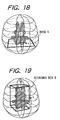
- a base S is designated at a position corresponding to the base of an object present in a closed area R (Fig. 18).
- the base S is set by designating the lowermost surface of an area (area having a three-dimensional spacial extent) where the object is present in the closed area.
- the object represented by the MVDS is a natural object, as can be seen from the fact that the object is photographed with a camera, and the object having a base is stable while it is placed on another object. For this reason, it can be considered that designation of the base is often effective in subsequent steps.
- the base may be designated on the basis of the camera arrangement and the arrangement information of the set table of the object in photographing the object. Alternatively, the base may be designated from an object in the photographed multi-viewpoint image.
- a point near the base of the object is designated in the image, and a straight line is obtained in the closed area R by reverse projection of the perspective projection in photographing. This operation is performed for images photographed at a plurality of camera positions, and the base is determined on the basis of the loci of resultant straight lines present in the space. Any other method may be used. With some method, the base S of the object in the closed area R is designated.
- step S502 coordinate transformation T for describing the coordinate relationship of the closed area R having the base S in the virtual space is prepared.
- the coordinate transformation T defines the position and direction of the base S viewed from the coordinate system of the virtual space.
- the coordinate transformation T has parameters for translation, rotation, and reduction. This coordinate transformation T is used in subsequent steps.
- step S601 the arrangement position and direction of the MVDS in the virtual space are determined. Since the geometric information of the base S is added to the MVDS, the MVDS can be determined to be set on another object (e.g., the floor or desk) in the virtual space. In addition, components of translation and rotation and the like are described by the coordinate transformation T on the basis of the determined arrangement information. With this processing, the object expressed by the MVDS can be arranged in the virtual space.
- step S602 it is determined whether the operation of the MVDS in the virtual space is to be started. In fact, it is assumed that virtual experience is being made while displaying the virtual space. It is determined whether, in this operation, the object expressed by the MVDS is allowed to be gripped and moved. If YES in step S602, the flow advances to step S603. In step S603, the coordinate transformation T is changed and updated on the basis of the operation, thereby translating and rotating the MVDS. If NO in step S602, the flow advances to step S604. It is determined in step S604 whether the operation is to be ended. If YES in step S604, the series of processing is ended. If NO in step S604, the flow returns to step S602.
- the object represented by the MVDS can be arranged and operated in the virtual space. Since the base is used as geometric information added to the MVDS, the object expressed by the MVDS can be arranged on another object. This also applies to translation and rotation. An operation restricted on another object is enabled. In addition, the arrangement or translation and rotation operations can also be automatically performed according to a predetermined procedure.
- steps S203 and S204 of the first embodiment are changed as will be described below. Processing in step S203 will be described with reference to Fig. 7, and processing in step S204 will be described with reference to Fig. 8.
- a bounding box B for limiting the presence area of an object present in a closed area R is designated (Fig. 19).
- the bounding box B is set by designating an area (area having a three-dimensional spacial extent) where the object is present in the closed area.
- a rectangular prism approximately representing the presence area of the object, or the like is designated.
- the bounding box may be designated on the basis of the camera arrangement and the arrangement information of the set table of the object in photographing the object, and the characteristic feature of the photographed multi-viewpoint image.
- the contour of the image on the image plane is obtained (or designated), and the contour curve is projected on the closed area R by reverse projection of the perspective projection in photographing.
- This operation is performed for images photographed at a plurality of camera positions, and an area enclosed by planes formed by projecting the contour line is obtained. A rectangular prism enclosing this area is set. Any other method may be used.
- the bounding box B of the object in the closed area R is designated.
- step S702 coordinate transformation T for describing the coordinate relationship of the closed area R having the bounding box B in the virtual space is prepared.
- the coordinate transformation T defines the position and direction of the bounding box B viewed from the coordinate system of the virtual space.
- the coordinate transformation T has parameters for translation, rotation, and reduction. This coordinate transformation T is used in subsequent steps.
- step S801 the arrangement position and direction of the MVDS in the virtual space are determined. Since the geometric information of the bounding box B is added to the MVDS, the MVDS can be determined to be set on another object (e.g., the floor or desk) or set while preventing interference with another object in the virtual space. In addition, components of translation and rotation and the like are described by the coordinate transformation T on the basis of the determined arrangement information. With this processing, the object expressed by the MVDS can be arranged in the virtual space.
- step S802 it is determined whether the operation of the MVDS in the virtual space is to be started. In fact, it is assumed that virtual experience is being made while displaying the virtual space. It is determined whether, in this operation, the object expressed by the MVDS is allowed to be gripped and moved. If YES in step S802, the flow advances to step S803. In step S803, the coordinate transformation T is changed and updated on the basis of the operation, thereby translating and rotating the MVDS. If NO in step S802, the flow advances to step S804. It is determined in step S804 whether the operation is to be ended. If YES in step S804, the flow returns to step S204. If NO in step S804, the flow returns to step S802.
- the object represented by the MVDS can be arranged and operated in the virtual space. Since the bounding box is used as geometric information added to the MVDS, the object expressed by the MVDS can be arranged on another object or arranged while preventing interference with another object. This also applied to translation and rotation. An operation restricted on another object or an operation for preventing rough interference with another object is enabled. In addition, the arrangement or translation and rotation operations can also be automatically performed according to a predetermined procedure.
- the same effect as that obtained when the shape data of an object having a very complex shape is generated or reproduced can be obtained by expressing the object by nongeometric model data without generating or reproducing the shape data.
- the entire virtual space can be generated without holding an enormous quantity of light space data.
- the object represented by the nongeometric model information can be used in the generated virtual space.
- the present invention can be applied to a system constituted by a plurality of devices, or to an apparatus comprising a single device. Furthermore, it goes without saying that the present invention is applicable also to a case where the invention is practiced by supplying a program to a system or apparatus. In this case, the program according to the present invention is loaded from a storage medium to the system or apparatus, thereby operating the system or apparatus in accordance with a predetermined method.
Landscapes
- Physics & Mathematics (AREA)
- Engineering & Computer Science (AREA)
- Computer Graphics (AREA)
- Geometry (AREA)
- Software Systems (AREA)
- General Physics & Mathematics (AREA)
- Theoretical Computer Science (AREA)
- Processing Or Creating Images (AREA)
- Image Generation (AREA)
Applications Claiming Priority (3)
| Application Number | Priority Date | Filing Date | Title |
|---|---|---|---|
| JP8265985A JPH10111953A (ja) | 1996-10-07 | 1996-10-07 | 画像処理方法および装置および記憶媒体 |
| JP265985/96 | 1996-10-07 | ||
| JP26598596 | 1996-10-07 |
Publications (3)
| Publication Number | Publication Date |
|---|---|
| EP0834837A2 true EP0834837A2 (de) | 1998-04-08 |
| EP0834837A3 EP0834837A3 (de) | 2000-01-05 |
| EP0834837B1 EP0834837B1 (de) | 2005-02-09 |
Family
ID=17424773
Family Applications (1)
| Application Number | Title | Priority Date | Filing Date |
|---|---|---|---|
| EP97307872A Expired - Lifetime EP0834837B1 (de) | 1996-10-07 | 1997-10-06 | Bildverarbeitungsgerät und -verfahren |
Country Status (4)
| Country | Link |
|---|---|
| US (1) | US6400373B1 (de) |
| EP (1) | EP0834837B1 (de) |
| JP (1) | JPH10111953A (de) |
| DE (1) | DE69732465T2 (de) |
Cited By (2)
| Publication number | Priority date | Publication date | Assignee | Title |
|---|---|---|---|---|
| CN105528777A (zh) * | 2014-10-21 | 2016-04-27 | 伊斯拉表面视觉有限公司 | 用于确定三维畸变的方法和装置 |
| US10289895B2 (en) | 2014-10-21 | 2019-05-14 | Isra Surface Vision Gmbh | Method and device for determining a three-dimensional distortion |
Families Citing this family (15)
| Publication number | Priority date | Publication date | Assignee | Title |
|---|---|---|---|---|
| US6674922B1 (en) | 1999-03-26 | 2004-01-06 | Canon Kabushiki Kaisha | Image processing method, image processing apparatus, and storage medium |
| EP1189171A2 (de) * | 2000-09-08 | 2002-03-20 | Fraunhofer-Gesellschaft zur Förderung der angewandten Forschung e.V. | Verfahren zum Erzeugen eines Bildes in einem virtuellen Studio |
| WO2002073955A1 (en) * | 2001-03-13 | 2002-09-19 | Canon Kabushiki Kaisha | Image processing apparatus, image processing method, studio apparatus, storage medium, and program |
| US7123257B2 (en) * | 2001-07-31 | 2006-10-17 | Canon Kabushiki Kaisha | Coloring information adding method and apparatus, and image processing method and apparatus |
| JP4115188B2 (ja) * | 2002-07-19 | 2008-07-09 | キヤノン株式会社 | 仮想空間描画表示装置 |
| KR100579135B1 (ko) * | 2004-11-11 | 2006-05-12 | 한국전자통신연구원 | 수렴형 3차원 다시점 영상 획득 방법 |
| JP4706965B2 (ja) * | 2005-08-31 | 2011-06-22 | 株式会社セガ | 画像生成プログラム、画像生成装置 |
| US7522164B2 (en) * | 2006-03-28 | 2009-04-21 | International Business Machines Corporation | Using self-adjustable three-dimensional matrix to simplify the construction of a complex 3D scene |
| US7750906B2 (en) * | 2006-04-19 | 2010-07-06 | Pixar | Systems and methods for light pruning |
| US20070285423A1 (en) * | 2006-06-08 | 2007-12-13 | Pixar | Splat Lights |
| CN102243074B (zh) * | 2010-05-13 | 2014-06-18 | 中国科学院遥感应用研究所 | 基于光线追踪技术的航空遥感成像几何变形仿真方法 |
| US8411092B2 (en) * | 2010-06-14 | 2013-04-02 | Nintendo Co., Ltd. | 2D imposters for simplifying processing of plural animation objects in computer graphics generation |
| CN102346922B (zh) * | 2010-07-30 | 2013-09-18 | 中国科学院遥感应用研究所 | 航天遥感载荷成像几何畸变三维可视化仿真方法 |
| US20140253540A1 (en) * | 2013-03-07 | 2014-09-11 | Yoav DORI | Method and system of incorporating real world objects into a virtual environment |
| CN112927340B (zh) * | 2021-04-06 | 2023-12-01 | 中国科学院自动化研究所 | 一种不依赖于机械摆放的三维重建加速方法、系统及设备 |
Family Cites Families (4)
| Publication number | Priority date | Publication date | Assignee | Title |
|---|---|---|---|---|
| US4970666A (en) * | 1988-03-30 | 1990-11-13 | Land Development Laboratory, Inc. | Computerized video imaging system for creating a realistic depiction of a simulated object in an actual environment |
| US5490239A (en) * | 1992-10-01 | 1996-02-06 | University Corporation For Atmospheric Research | Virtual reality imaging system |
| US5689628A (en) * | 1994-04-14 | 1997-11-18 | Xerox Corporation | Coupling a display object to a viewpoint in a navigable workspace |
| US5850352A (en) * | 1995-03-31 | 1998-12-15 | The Regents Of The University Of California | Immersive video, including video hypermosaicing to generate from multiple video views of a scene a three-dimensional video mosaic from which diverse virtual video scene images are synthesized, including panoramic, scene interactive and stereoscopic images |
-
1996
- 1996-10-07 JP JP8265985A patent/JPH10111953A/ja active Pending
-
1997
- 1997-10-03 US US08/943,699 patent/US6400373B1/en not_active Expired - Lifetime
- 1997-10-06 EP EP97307872A patent/EP0834837B1/de not_active Expired - Lifetime
- 1997-10-06 DE DE69732465T patent/DE69732465T2/de not_active Expired - Lifetime
Non-Patent Citations (2)
| Title |
|---|
| BLONDE L ET AL: "A VIRTUAL STUDIO FOR LIVE BROADCASTING: THE MONA LISA PROJECT" IEEE MULTIMEDIA, vol. 3, no. 2, 1 June 1996 (1996-06-01), pages 18-28, XP000594152 ISSN: 1070-986X * |
| SHENCHANG ERIC CHEN: "QUICKTIME VR - AN IMAGE-BASED APPROACH TO VIRTUAL ENVIRONMENT NAVIGATION" COMPUTER GRAPHICS PROCEEDINGS, LOS ANGELES, AUG. 6 - 11, 1995, 6 August 1995 (1995-08-06), pages 29-38, XP000546213 COOK R ISBN: 0-89791-701-4 * |
Cited By (3)
| Publication number | Priority date | Publication date | Assignee | Title |
|---|---|---|---|---|
| CN105528777A (zh) * | 2014-10-21 | 2016-04-27 | 伊斯拉表面视觉有限公司 | 用于确定三维畸变的方法和装置 |
| EP3012578A3 (de) * | 2014-10-21 | 2016-06-01 | Isra Surface Vision GmbH | Verfahren und vorrichtung zur ermittlung einer dreidimensionalen verzerrung |
| US10289895B2 (en) | 2014-10-21 | 2019-05-14 | Isra Surface Vision Gmbh | Method and device for determining a three-dimensional distortion |
Also Published As
| Publication number | Publication date |
|---|---|
| DE69732465D1 (de) | 2005-03-17 |
| JPH10111953A (ja) | 1998-04-28 |
| US6400373B1 (en) | 2002-06-04 |
| DE69732465T2 (de) | 2006-01-12 |
| EP0834837A3 (de) | 2000-01-05 |
| EP0834837B1 (de) | 2005-02-09 |
Similar Documents
| Publication | Publication Date | Title |
|---|---|---|
| EP0834837B1 (de) | Bildverarbeitungsgerät und -verfahren | |
| EP0794516B1 (de) | Verfahren und Vorrichtung zur Bildverarbeitung | |
| US6525728B2 (en) | Method and apparatus for using a general three-dimensional (3D) graphics pipeline for cost effective digital image and video editing, transformation, and representation | |
| US5969722A (en) | Methods and apparatus for creation of three-dimensional wire frames and for three-dimensional stereo morphing | |
| US5790713A (en) | Three-dimensional computer graphics image generator | |
| JP3964749B2 (ja) | 三次元シーンでイメージベースのレンダリング情報を表現するための方法 | |
| JPH0757117A (ja) | テクスチャマップへの索引を生成する方法及びコンピュータ制御表示システム | |
| JPH10255081A (ja) | 画像処理方法及び画像処理装置 | |
| US5793372A (en) | Methods and apparatus for rapidly rendering photo-realistic surfaces on 3-dimensional wire frames automatically using user defined points | |
| JP2832463B2 (ja) | 3次元モデルの再構成方法および表示方法 | |
| KR100693134B1 (ko) | 3차원 이미지 처리 | |
| JP3309841B2 (ja) | 合成動画像生成装置および合成動画像生成方法 | |
| JP3577202B2 (ja) | 映像作成装置 | |
| Pavlidis et al. | Preservation of architectural heritage through 3D digitization | |
| Soh et al. | Texture mapping of 3D human face for virtual reality environments | |
| JPH09134449A (ja) | 立体モデルのテクスチャマッピング方法 | |
| JPH1027268A (ja) | 画像処理方法及び画像処理装置 | |
| JP2000511658A (ja) | 三次元ワイヤーフレームの創成と三次元ステレオモーフィングのための方法及び装置 | |
| CN115857163A (zh) | 一种基于OsgEarth的全息智能沙盘展示方法及装置及介质 | |
| JP2001084408A (ja) | 3次元データ加工装置及び方法並びに記録媒体 | |
| EP1398734A2 (de) | Texturabbildungsverfahren | |
| JP3648099B2 (ja) | 画像合成表示方法および装置ならびに画像合成表示プログラムを記録した記録媒体 | |
| Kaneko et al. | View interpolation with range data for navigation applications | |
| JP2007299080A (ja) | 画像生成方法及び画像生成装置 | |
| JP2002312810A (ja) | 合成動画像生成装置および合成動画像生成方法 |
Legal Events
| Date | Code | Title | Description |
|---|---|---|---|
| PUAI | Public reference made under article 153(3) epc to a published international application that has entered the european phase |
Free format text: ORIGINAL CODE: 0009012 |
|
| AK | Designated contracting states |
Kind code of ref document: A2 Designated state(s): DE FR GB IT NL |
|
| AX | Request for extension of the european patent |
Free format text: AL;LT;LV;RO;SI |
|
| PUAL | Search report despatched |
Free format text: ORIGINAL CODE: 0009013 |
|
| AK | Designated contracting states |
Kind code of ref document: A3 Designated state(s): AT BE CH DE DK ES FI FR GB GR IE IT LI LU MC NL PT SE |
|
| AX | Request for extension of the european patent |
Free format text: AL;LT;LV;RO;SI |
|
| 17P | Request for examination filed |
Effective date: 20000522 |
|
| AKX | Designation fees paid |
Free format text: DE FR GB IT NL |
|
| 17Q | First examination report despatched |
Effective date: 20020617 |
|
| GRAP | Despatch of communication of intention to grant a patent |
Free format text: ORIGINAL CODE: EPIDOSNIGR1 |
|
| GRAS | Grant fee paid |
Free format text: ORIGINAL CODE: EPIDOSNIGR3 |
|
| GRAA | (expected) grant |
Free format text: ORIGINAL CODE: 0009210 |
|
| AK | Designated contracting states |
Kind code of ref document: B1 Designated state(s): DE FR GB IT NL |
|
| PG25 | Lapsed in a contracting state [announced via postgrant information from national office to epo] |
Ref country code: NL Free format text: LAPSE BECAUSE OF FAILURE TO SUBMIT A TRANSLATION OF THE DESCRIPTION OR TO PAY THE FEE WITHIN THE PRESCRIBED TIME-LIMIT Effective date: 20050209 Ref country code: IT Free format text: LAPSE BECAUSE OF FAILURE TO SUBMIT A TRANSLATION OF THE DESCRIPTION OR TO PAY THE FEE WITHIN THE PRESCRIBED TIME-LIMIT;WARNING: LAPSES OF ITALIAN PATENTS WITH EFFECTIVE DATE BEFORE 2007 MAY HAVE OCCURRED AT ANY TIME BEFORE 2007. THE CORRECT EFFECTIVE DATE MAY BE DIFFERENT FROM THE ONE RECORDED. Effective date: 20050209 |
|
| REG | Reference to a national code |
Ref country code: GB Ref legal event code: FG4D |
|
| REF | Corresponds to: |
Ref document number: 69732465 Country of ref document: DE Date of ref document: 20050317 Kind code of ref document: P |
|
| NLV1 | Nl: lapsed or annulled due to failure to fulfill the requirements of art. 29p and 29m of the patents act | ||
| PLBE | No opposition filed within time limit |
Free format text: ORIGINAL CODE: 0009261 |
|
| ET | Fr: translation filed | ||
| 26N | No opposition filed |
Effective date: 20051110 |
|
| PGFP | Annual fee paid to national office [announced via postgrant information from national office to epo] |
Ref country code: DE Payment date: 20141031 Year of fee payment: 18 Ref country code: GB Payment date: 20141021 Year of fee payment: 18 Ref country code: FR Payment date: 20141027 Year of fee payment: 18 |
|
| REG | Reference to a national code |
Ref country code: DE Ref legal event code: R119 Ref document number: 69732465 Country of ref document: DE |
|
| GBPC | Gb: european patent ceased through non-payment of renewal fee |
Effective date: 20151006 |
|
| PG25 | Lapsed in a contracting state [announced via postgrant information from national office to epo] |
Ref country code: GB Free format text: LAPSE BECAUSE OF NON-PAYMENT OF DUE FEES Effective date: 20151006 Ref country code: DE Free format text: LAPSE BECAUSE OF NON-PAYMENT OF DUE FEES Effective date: 20160503 |
|
| REG | Reference to a national code |
Ref country code: FR Ref legal event code: ST Effective date: 20160630 |
|
| PG25 | Lapsed in a contracting state [announced via postgrant information from national office to epo] |
Ref country code: FR Free format text: LAPSE BECAUSE OF NON-PAYMENT OF DUE FEES Effective date: 20151102 |