EP0834204B1 - Connector apparatus - Google Patents
Connector apparatus Download PDFInfo
- Publication number
- EP0834204B1 EP0834204B1 EP96945130A EP96945130A EP0834204B1 EP 0834204 B1 EP0834204 B1 EP 0834204B1 EP 96945130 A EP96945130 A EP 96945130A EP 96945130 A EP96945130 A EP 96945130A EP 0834204 B1 EP0834204 B1 EP 0834204B1
- Authority
- EP
- European Patent Office
- Prior art keywords
- module
- mastering
- insulation displacement
- leadframe
- socket
- Prior art date
- Legal status (The legal status is an assumption and is not a legal conclusion. Google has not performed a legal analysis and makes no representation as to the accuracy of the status listed.)
- Expired - Lifetime
Links
Images


Classifications
-
- H—ELECTRICITY
- H01—ELECTRIC ELEMENTS
- H01R—ELECTRICALLY-CONDUCTIVE CONNECTIONS; STRUCTURAL ASSOCIATIONS OF A PLURALITY OF MUTUALLY-INSULATED ELECTRICAL CONNECTING ELEMENTS; COUPLING DEVICES; CURRENT COLLECTORS
- H01R43/00—Apparatus or processes specially adapted for manufacturing, assembling, maintaining, or repairing of line connectors or current collectors or for joining electric conductors
- H01R43/20—Apparatus or processes specially adapted for manufacturing, assembling, maintaining, or repairing of line connectors or current collectors or for joining electric conductors for assembling or disassembling contact members with insulating base, case or sleeve
- H01R43/24—Assembling by moulding on contact members
-
- H—ELECTRICITY
- H01—ELECTRIC ELEMENTS
- H01R—ELECTRICALLY-CONDUCTIVE CONNECTIONS; STRUCTURAL ASSOCIATIONS OF A PLURALITY OF MUTUALLY-INSULATED ELECTRICAL CONNECTING ELEMENTS; COUPLING DEVICES; CURRENT COLLECTORS
- H01R13/00—Details of coupling devices of the kinds covered by groups H01R12/70 or H01R24/00 - H01R33/00
- H01R13/40—Securing contact members in or to a base or case; Insulating of contact members
- H01R13/405—Securing in non-demountable manner, e.g. moulding, riveting
-
- H—ELECTRICITY
- H01—ELECTRIC ELEMENTS
- H01R—ELECTRICALLY-CONDUCTIVE CONNECTIONS; STRUCTURAL ASSOCIATIONS OF A PLURALITY OF MUTUALLY-INSULATED ELECTRICAL CONNECTING ELEMENTS; COUPLING DEVICES; CURRENT COLLECTORS
- H01R13/00—Details of coupling devices of the kinds covered by groups H01R12/70 or H01R24/00 - H01R33/00
- H01R13/46—Bases; Cases
- H01R13/514—Bases; Cases composed as a modular blocks or assembly, i.e. composed of co-operating parts provided with contact members or holding contact members between them
-
- H—ELECTRICITY
- H01—ELECTRIC ELEMENTS
- H01R—ELECTRICALLY-CONDUCTIVE CONNECTIONS; STRUCTURAL ASSOCIATIONS OF A PLURALITY OF MUTUALLY-INSULATED ELECTRICAL CONNECTING ELEMENTS; COUPLING DEVICES; CURRENT COLLECTORS
- H01R2201/00—Connectors or connections adapted for particular applications
- H01R2201/16—Connectors or connections adapted for particular applications for telephony
-
- H—ELECTRICITY
- H01—ELECTRIC ELEMENTS
- H01R—ELECTRICALLY-CONDUCTIVE CONNECTIONS; STRUCTURAL ASSOCIATIONS OF A PLURALITY OF MUTUALLY-INSULATED ELECTRICAL CONNECTING ELEMENTS; COUPLING DEVICES; CURRENT COLLECTORS
- H01R24/00—Two-part coupling devices, or either of their cooperating parts, characterised by their overall structure
- H01R24/60—Contacts spaced along planar side wall transverse to longitudinal axis of engagement
- H01R24/62—Sliding engagements with one side only, e.g. modular jack coupling devices
-
- H—ELECTRICITY
- H01—ELECTRIC ELEMENTS
- H01R—ELECTRICALLY-CONDUCTIVE CONNECTIONS; STRUCTURAL ASSOCIATIONS OF A PLURALITY OF MUTUALLY-INSULATED ELECTRICAL CONNECTING ELEMENTS; COUPLING DEVICES; CURRENT COLLECTORS
- H01R4/00—Electrically-conductive connections between two or more conductive members in direct contact, i.e. touching one another; Means for effecting or maintaining such contact; Electrically-conductive connections having two or more spaced connecting locations for conductors and using contact members penetrating insulation
- H01R4/24—Connections using contact members penetrating or cutting insulation or cable strands
- H01R4/2416—Connections using contact members penetrating or cutting insulation or cable strands the contact members having insulation-cutting edges, e.g. of tuning fork type
- H01R4/242—Connections using contact members penetrating or cutting insulation or cable strands the contact members having insulation-cutting edges, e.g. of tuning fork type the contact members being plates having a single slot
- H01R4/2425—Flat plates, e.g. multi-layered flat plates
- H01R4/2429—Flat plates, e.g. multi-layered flat plates mounted in an insulating base
Definitions
- the present invention relates to connector apparatus, for example for use in telecommunications applications, such as telephone sockets.
- connector apparatus for use with telecommunications equipment, having a modular construction such that different modules can be incorporated in a common housing structure to provide connectors having different functionality, for example single or double sockets, and/or primary or secondary telephone connectors.
- the modules are based around printed circuit boards such that the necessary components (for example, mastering components) require soldering to the boards, and also the various connectors have to be mounted on the boards and soldered in place. Assembly of the printed circuit boards requires at least some manual operator intervention since it is not readily fully automatable.
- the wire insulation displacement portions are exposed from the housing so as to receive insulated telephone wires.
- the cantilever jack contact portions are exposed adjacent a cavity for a standard telephone plug, so that the contact portions can be bent into the cavity.
- US-A-5 074 804 discloses a connector having first and second connecting elements, the first elements receiving insulated wires and the second set defining contacts for connection to an associated plug such as a telephone jack.
- DE-C-4 323 827 discloses a pluggable assembly including connections made of punched leadframes embedded in a printed circuit board. Flat plugs are integrally formed by the leadframes, and components may be mounted to bent tabs of the leadframes.
- a method of manufacturing a connector module comprising:
- a connector module comprising:
- the module structure is formed by overmoulding part of the leadframe structure with a plastics material
- wiring connections are made by means of insulation displacement contacts (IDCs) and these also form part of the leadframe.
- IDCs insulation displacement contacts
- One embodiment of the invention provides an effective IDC construction in which each IDC conductor is provided with an aperture for cable insertion, the aperture being preferably of oval shape, and an insulation displacement slot opening from an end of the aperture, the slot preferably having parallel sides. Since the cable insertion aperture is not open at the end, as with existing designs, there is greater structural integrity to the connector and the sides of the connector on each side of the insulation displacement slot are significantly less susceptible to splaying apart when a cable is pushed down into the slot. In addition, the closed nature of the cable entry eyelet provides cable capture during wiring.
- Particular embodiments of the invention provide a modular design line jack unit system incorporating a single module of integral metal leadframe design, with IDC connectors and a telecom socket, fully enclosed in a high temperature industrial plastics structure.
- This module includes appropriate sockets to accommodate mastering component plug-in assemblies, and can be snap fitted into a flush mounting backbox, such as a 67 mm x 67 mm backbox or a 85 mm x 85 mm backbox.
- the backbox is designed to eliminate moisture ingress, and to include an improved cable management system, also offering the user the choice of rear or side cable entry access.
- the metal leadframe module situated within a closed chamber of the backbox, the module could, if necessary, be encapsulated in a protective material for use in adverse environmental locations.
- the module can be used in both voice and data socket connection systems.
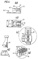
- FIG. 1 shows a connection module 10 which, as will be described below, forms part of a telephone socket assembly.
- the module 10 includes IDC contacts 12 for connection to a telephone cable (not shown), a telecom socket 14, and an area 16 provided for a mastering component module (not shown), with sockets 18 in that area 16 for receiving terminals of the mastering component module.
- the connection module 10 is formed of an encapsulated leadframe structure, the assembly being further described with reference to Figures 2 and 3.
- a basic leadframe 20 is provided for the interconnections of the module 10.
- Parts of the leadframe 20 define the IDC contacts 12 and the sockets 18 for the mastering components.
- the lower part (2B) of Figure 2 shows the leadframe 20 after plastics overmoulding 22 to provide the module structure. It will be seen that parts 24 of the overmoulding provide the mastering component module area, as well as the IDC base structure. Attachment points 26 are provided for the telecom socket contacts.
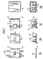
- FIG 3 shows three further steps in the assembly process.
- the supporting framework (28; see Figure 2) of the leadframe structure 20 has been broken away, separating the individual modules 10, and with the provision of a telecom socket contacts support arm 30.
- the telecom socket contacts 32 are positioned over the contacts support arm 30, and the IDC contacts 12 are bent upwards; in part 3C, a moulded plastics cover 36 forming the housing for both the telecom socket 14 and the IDC assembly is attached to the module 10.
- FIG. 4 shows the IDC wiring system in more detail.
- Each IDC contact 12 includes a cable entry eyelet 40 in the form of an oval aperture, with an insulation displacement slot 42 opening from an end of the eyelet, the slot 42 preferably having parallel sides.
- the cable insertion aperture is not open at the end, as is the case with existing designs, and this provides greater structural integrity to the contact since the tines do not spread, even after repeated use. Also the closed nature of the cable entry eyelet provides cable capture during wiring.
- the connector housing 44 includes slots 46 aligned with the insulation displacement slots 42 of the contacts 12, and the housing slots 46 act as grips for the wire insulation, keeping the cables 48 in place.
- Part 4D of Figure 4 shows an IDC insertion tool 49, such as a standard BT wiring tool 2A (or its plastics equivalent) aligned with the module 10 for cable insertion.
- FIG. 5 shows the connection module 10 ready for connection to a telephone mastering module 50.
- the mastering module 50 has terminals 52 for connecting with the sockets provided in the connection module.
- the mastering module 50 is provided as a separate structure since it will only need to be attached if the socket housing is to be a master socket.
- the preferred structure of the mastering module 50 is, again, based on a leadframe construction encapsulated in plastics, with an integral plastics protective cover, as will be described.
- Figures 6 and 7 show assembly of the mastering module 50, the assembly being similar to that of the connection module 10.
- the basic leadframe 60 is shown at the top (6A), with plastics overmoulding 62 shown in the lower part (6B) of the drawing.
- Plug-in connection terminals 64 can be seen near the corners of the overmouldings 62.
- Component termination points 66 form part of the leadframe 60.
- Figure 7 shows (7A) the moulded leadframe assembly 70 remaining after the supporting framework of the leadframe has been broken away, (7B) with the contacts and connectors 66 bent as required, (7C) with mastering components (such as a capacitor 72, resistor 74 and GDT 76) assembled in place, such as by soldering, and (7D) with a plastics moulded cover 78 over the assembly 70 and mastering components.
- mastering components such as a capacitor 72, resistor 74 and GDT 76
- Figure 8 shows plan and side views of the completed connection module 10 with mastering components module 50.
- mastering module 50 Various type of mastering module 50 are available, including a telex mastering version.
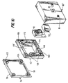
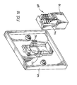
- FIG. 9 shows, in exploded form, a socket assembly in which the connection module 10 and mastering module 50 are retained between front and rear housing cover parts 80,82.
- the socket assembly as shown is for a single socket. Some aspects of the socket assembly are similar to those disclosed in the above-mentioned GB-A-2 282 273.
- the front housing cover part 80 is retained by means of captive fixing screws 81.
- the rear housing cover part 82 includes: wall fixing holes 83 with integral alignment facility; rear stand-off ribs 84 to eliminate moisture entrapment; front cover screw fixings 85 for accepting the captive fixing screws 81; side cable entry knockouts 86; a rear access cable entry 87; a cable management channel 88; and a moisture resistant cavity 89 for receiving the connection module 10.
- the rear housing cover part 82 provides a low profile surface mount back box.
- connection module 10 (if appropriate, with a mastering module 50) is inserted within the cavity 89 and retained in position by the front cover part 80.
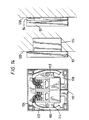
- Figures 10 and 11 show larger socket assemblies, capable of incorporating two sockets.
- Figure 10 only one socket is provided whereas Figure 11 includes two sockets by virtue of two connection modules 10 being included within the rear cover cavity 89'.
- the rear part of the housing is in the form of a low profile flush mount back box 92 with (optional) low profile frame 94 for surface mounting.
- Rear stand-off ribs 96 to eliminate moisture entrapment are provided on the frame 94 which also has cable entry knockouts 98, alignment location posts 102 and wall fixing holes 104 with integral alignment facility, these also being provided in the back box 92.
- the back box 92 also includes a cable management channel 106, a rear access cable entry 108, a surface access cable entry 110, metal back-box screw fixing holes 112, front cover screw fittings 114 and a moisture resistant cavity 89' for the module(s) 10.
- Figures 12 to 14 show different ways of attaching the socket assemblies of Figures 9 to 11, either by flush mounting or surface mounting, and also shows the telephone cable management within the assembly and the attachment to the IDC connector.
- the assembly of Figure 9 is shown surface mounted to a wall 120.
- the cable management channel 88 accepts two cable 122 diameters either side. This is only one wiring example; the rear access cable entry 87 can alternatively be utilised.
- Figures 13 and 14 respectively show the assemblies of Figures 10 and 11 in both surface mounted and flush mounted form.
- the wall 120 includes a metal back-box 124 and the frame 94 is omitted.
- the general arrangements are similar to that of Figure 12 and again two cable 122 diameters can be accepted either side in the cable management channel 106.
- FIG. 15 shows a facia mounting assembly 130 provided with a simplified connection module 10' not including mastering components.
- the connection module is similar to that previously described in that leadframe construction is provided for the IDC connector and connecting conductors within the module 10'.
- the assembly 130 includes a cover plate 132 and a snap-fit facia assembly 134.
- the connection module 10' is fitted in an aperture 136 of the cover plate 132 and retained in position when the facia assembly 134 is snap-fitted into place.
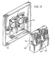
- Figures 16 to 18 show further facia mounting assemblies broadly similar to that of Figure 15 but having the further advantage that the connection module 10" can snap-fit directly to the facia front cover 140, no other housing parts being required, since snap-fitting projections 142 on the cover 140 fit into corresponding cut-outs 144 on the module 10". Also, the connection module 10" has provision for a mastering components module 50 so that the resulting socket assembly can be used as a master socket.
- Figures 16 and 18 are for single sockets ( Figure 16 having a 85 mm x 85 mm front cover, and Figure 18 having a 67 mm x 67 mm front cover) and Figure 17 provides a double socket (85 mm x 85 mm front cover).
- Figure 19 shows a terminal box 150 including a self-locking leadframe connection module 152 provided with IDC connectors 12.
- the connection module is made in a similar manner to that described above, namely by overmoulding a basic leadframe, breaking away the supporting structure, and attaching a housing support structure for completing the IDC housing which is similar to that of Figure 4 and has similar advantages.
- the connection module 152 is retained between a surface mount back-box 154 and a front cover 156 provided with cover retaining catches 158.
- the back-box 154 includes corresponding cover retaining parts 160, a cable restraint tie 162, connection module retaining clips 164, a cable entry 166 and a wall fixing hole 168.
Description
- the module structure is formed by overmoulding part of the leadframe structure with a plastics material;
- a socket contact support arm is attached to the socket contact attachment points; and
- socket contacts are positioned over the socket contact support arm.
Claims (15)
- A method of manufacturing a connector module, the method comprising:characterised in that:providing a leadframe structure (20) carrying conductors of the module and insulation displacement contacts (12) by means of a supporting framework (28);forming a module structure (22) having socket contact attachment points (26);breaking away the supporting framework (28) from the leadframe structure (20);bending parts of the remaining leadframe structure (20) including the insulation displacement contacts (12); andattaching a housing cover (36) to the module structure (22);the module structure (22) is formed by overmoulding part of the leadframe structure (20) with a plastics material;a socket contact support arm (30) is attached to the socket contact attachment points (26); andsocket contacts (32) are positioned over the socket contact support arm (30).
- A method according to claim 1, wherein the leadframe structure (20) includes conductor contacts (18) for connection to a mastering module (50).
- A method according to claim 2, including the step of attaching the mastering module (50) to the conductor contacts (18) of the leadframe structure (20), after the housing cover (36) has been attached to the module structure (22).
- A method according to claim 2 or claim 3, wherein the mastering module (50) is manufactured by:providing a second leadframe structure (60) carrying conductors of the mastering module (50), connection terminals (64) and component termination points (66) by means of a supporting framework;overmoulding part of the second leadframe structure (60) with a plastics material to form a mastering module structure (62);breaking away the supporting framework from the second leadframe structure (60);bending parts of the remaining leadframe structure (60) including the connection terminals (64) and component termination points (66);connecting mastering components (72,74,76) to the component termination points (66); andattaching a mastering module housing cover (78) to the mastering module structure (62).
- A method according to any one of the preceding claims, wherein each insulation displacement contact (12) on the leadframe structure (20) includes a conductor provided with a closed aperture (40) for cable insertion and retention.
- A method according to claim 5, wherein the closed aperture (40) of the insulation displacement contact is of oval shape.
- A method according to claim 6, wherein the conductor of the insulation displacement contact includes an insulation displacement slot (46) opening from an end of the aperture (40).
- A method according to claim 7, wherein the insulation displacement slot (46) has substantially parallel sides.
- A connector module comprising:characterised in that:a leadframe structure (20) carrying conductors of the module and insulation displacement contacts (12);a module structure (22) having socket contact attachment points (26);socket contacts (32); anda housing cover (36) attached to the module structure (22);the module structure (22) is formed by overmoulding part of the leadframe structure (20) with a plastics material;a socket contact support arm (30) is attached to the socket contact attachment points (26); andthe socket contacts (32) are positioned over the socket contact support arm (30).
- A connector module according to claim 9, wherein the leadframe structure (20) includes conductor contacts (18) for connection to a mastering module (50).
- A connector module according to claim 10, wherein the mastering module (50) comprises:a second leadframe structure (60) carrying conductors of the mastering module (10), connection terminals (64) and component termination points (66);a mastering module structure (62) formed by overmoulding part of the second leadframe structure (60) with a plastics material;mastering components (72,74,76) connected to the component termination points (66); anda mastering module housing cover (78) attached to the mastering module structure (62).
- A connector module according to any one of claims 9 to 11, wherein each insulation displacement contact (12) on the leadframe structure (20) includes a conductor provided with a closed aperture (40) for cable insertion and retention.
- A connector module according to claim 12, wherein the closed aperture (40) of the insulation displacement contact (12) is of oval shape.
- A connector module according to claim 13, wherein the conductor of the insulation displacement contact (12) includes an insulation displacement slot (46) opening from an end of the aperture (40).
- A connector module according to claim 14, wherein the insulation displacement slot (46) has substantially parallel sides.
Applications Claiming Priority (3)
| Application Number | Priority Date | Filing Date | Title |
|---|---|---|---|
| GB9511777A GB9511777D0 (en) | 1995-06-09 | 1995-06-09 | Connector apparatus |
| GB9511777 | 1995-06-09 | ||
| PCT/GB1996/001394 WO1996042125A1 (en) | 1995-06-09 | 1996-06-10 | Connector apparatus |
Publications (2)
| Publication Number | Publication Date |
|---|---|
| EP0834204A1 EP0834204A1 (en) | 1998-04-08 |
| EP0834204B1 true EP0834204B1 (en) | 1999-03-17 |
Family
ID=10775834
Family Applications (1)
| Application Number | Title | Priority Date | Filing Date |
|---|---|---|---|
| EP96945130A Expired - Lifetime EP0834204B1 (en) | 1995-06-09 | 1996-06-10 | Connector apparatus |
Country Status (6)
| Country | Link |
|---|---|
| EP (1) | EP0834204B1 (en) |
| AU (1) | AU707206B2 (en) |
| GB (1) | GB9511777D0 (en) |
| HK (1) | HK1005816A1 (en) |
| NZ (1) | NZ311569A (en) |
| WO (1) | WO1996042125A1 (en) |
Families Citing this family (2)
| Publication number | Priority date | Publication date | Assignee | Title |
|---|---|---|---|---|
| EP1693933A1 (en) | 2005-02-17 | 2006-08-23 | Reichle & De-Massari AG | Connector for data transmission via electrical wires |
| FR2980049B1 (en) * | 2011-09-09 | 2019-04-05 | Omelcom | INTERNAL TERMINATION DEVICE |
Family Cites Families (5)
| Publication number | Priority date | Publication date | Assignee | Title |
|---|---|---|---|---|
| GB2093280B (en) * | 1981-02-13 | 1984-11-14 | Smiths Industries Ltd | Insulation piercing contacts |
| GB2242080B (en) * | 1990-03-09 | 1994-12-21 | Krone Ag | Electrical connectors |
| SG44685A1 (en) * | 1992-06-24 | 1997-12-19 | Molex Inc | Modular electrical connector |
| DE4323827C1 (en) * | 1993-07-15 | 1994-12-08 | Siemens Ag | Pluggable assembly |
| GB2311421B (en) * | 1993-09-23 | 1998-01-14 | Astralux Dynamics Ltd | Telecommunications connection apparatus |
-
1995
- 1995-06-09 GB GB9511777A patent/GB9511777D0/en active Pending
-
1996
- 1996-06-10 WO PCT/GB1996/001394 patent/WO1996042125A1/en active IP Right Grant
- 1996-06-10 EP EP96945130A patent/EP0834204B1/en not_active Expired - Lifetime
- 1996-06-10 NZ NZ311569A patent/NZ311569A/en unknown
- 1996-06-10 AU AU62201/96A patent/AU707206B2/en not_active Ceased
-
1998
- 1998-06-05 HK HK98104995A patent/HK1005816A1/en not_active IP Right Cessation
Also Published As
| Publication number | Publication date |
|---|---|
| AU6220196A (en) | 1997-01-09 |
| AU707206B2 (en) | 1999-07-08 |
| NZ311569A (en) | 1999-04-29 |
| WO1996042125A1 (en) | 1996-12-27 |
| GB9511777D0 (en) | 1995-08-02 |
| HK1005816A1 (en) | 1999-01-29 |
| EP0834204A1 (en) | 1998-04-08 |
Similar Documents
| Publication | Publication Date | Title |
|---|---|---|
| US5735714A (en) | Information management outlet module and assembly providing protection to exposed cabling | |
| US5647763A (en) | Multi-media cross connect system | |
| AU601107B2 (en) | Connecting block construction | |
| US4838811A (en) | Modular connector with EMI countermeasure | |
| US5860829A (en) | Cross connect terminal block | |
| US5562493A (en) | Network interface assembly and mounting frame | |
| US8058552B2 (en) | Electrical wiring system | |
| US5074804A (en) | Electrical connectors | |
| US6004163A (en) | Electrical multi-pole plug-and-socket-type connector with associated socket part | |
| CA2174268C (en) | Connector modules | |
| US6795320B2 (en) | Method and apparatus for supplying data and power to panel-supported components | |
| CA1223656A (en) | Network interface device | |
| WO1995031840A1 (en) | Communications connectors | |
| US4865564A (en) | Wall mounted connecting block | |
| KR20140022736A (en) | Modular plug | |
| KR970001618B1 (en) | Telecommunication outlet | |
| US5483409A (en) | 25-pair circuit protection assembly | |
| US5509812A (en) | Cable tap assembly | |
| JPH10189120A (en) | Shielded multipolar cable plug | |
| US4737888A (en) | Receptacle assembly and mounting bracket for circuit board connections | |
| EP0623976A2 (en) | Module for telephone line conductor pair having single protector unit | |
| US6652295B1 (en) | Ground bus for junction box | |
| US4580864A (en) | Modular connecting blocks | |
| EP0834204B1 (en) | Connector apparatus | |
| US6383025B1 (en) | Cable connector assembly |
Legal Events
| Date | Code | Title | Description |
|---|---|---|---|
| PUAI | Public reference made under article 153(3) epc to a published international application that has entered the european phase |
Free format text: ORIGINAL CODE: 0009012 |
|
| 17P | Request for examination filed |
Effective date: 19980109 |
|
| AK | Designated contracting states |
Kind code of ref document: A1 Designated state(s): GB IE |
|
| GRAG | Despatch of communication of intention to grant |
Free format text: ORIGINAL CODE: EPIDOS AGRA |
|
| GRAG | Despatch of communication of intention to grant |
Free format text: ORIGINAL CODE: EPIDOS AGRA |
|
| GRAH | Despatch of communication of intention to grant a patent |
Free format text: ORIGINAL CODE: EPIDOS IGRA |
|
| 17Q | First examination report despatched |
Effective date: 19980828 |
|
| GRAH | Despatch of communication of intention to grant a patent |
Free format text: ORIGINAL CODE: EPIDOS IGRA |
|
| GRAA | (expected) grant |
Free format text: ORIGINAL CODE: 0009210 |
|
| AK | Designated contracting states |
Kind code of ref document: B1 Designated state(s): GB IE |
|
| REG | Reference to a national code |
Ref country code: IE Ref legal event code: FG4D |
|
| PLBE | No opposition filed within time limit |
Free format text: ORIGINAL CODE: 0009261 |
|
| STAA | Information on the status of an ep patent application or granted ep patent |
Free format text: STATUS: NO OPPOSITION FILED WITHIN TIME LIMIT |
|
| 26N | No opposition filed | ||
| PGFP | Annual fee paid to national office [announced via postgrant information from national office to epo] |
Ref country code: GB Payment date: 20010608 Year of fee payment: 6 |
|
| PGFP | Annual fee paid to national office [announced via postgrant information from national office to epo] |
Ref country code: IE Payment date: 20010611 Year of fee payment: 6 |
|
| REG | Reference to a national code |
Ref country code: GB Ref legal event code: IF02 |
|
| PG25 | Lapsed in a contracting state [announced via postgrant information from national office to epo] |
Ref country code: IE Free format text: LAPSE BECAUSE OF NON-PAYMENT OF DUE FEES Effective date: 20020610 Ref country code: GB Free format text: LAPSE BECAUSE OF NON-PAYMENT OF DUE FEES Effective date: 20020610 |
|
| GBPC | Gb: european patent ceased through non-payment of renewal fee |
Effective date: 20020610 |
|
| REG | Reference to a national code |
Ref country code: IE Ref legal event code: MM4A |