EP0833773B1 - Verbessertes umhüllungsverfahren und vorrichtung - Google Patents
Verbessertes umhüllungsverfahren und vorrichtung Download PDFInfo
- Publication number
- EP0833773B1 EP0833773B1 EP96918753A EP96918753A EP0833773B1 EP 0833773 B1 EP0833773 B1 EP 0833773B1 EP 96918753 A EP96918753 A EP 96918753A EP 96918753 A EP96918753 A EP 96918753A EP 0833773 B1 EP0833773 B1 EP 0833773B1
- Authority
- EP
- European Patent Office
- Prior art keywords
- film
- motor
- stretch
- motors
- hydraulic motor
- Prior art date
- Legal status (The legal status is an assumption and is not a legal conclusion. Google has not performed a legal analysis and makes no representation as to the accuracy of the status listed.)
- Expired - Lifetime
Links
- 238000000034 method Methods 0.000 title claims description 14
- 239000004460 silage Substances 0.000 claims abstract description 16
- 230000002093 peripheral effect Effects 0.000 claims abstract description 10
- 230000000694 effects Effects 0.000 claims description 4
- 238000011144 upstream manufacturing Methods 0.000 claims description 2
- 239000003921 oil Substances 0.000 description 25
- 238000005538 encapsulation Methods 0.000 description 10
- 239000010720 hydraulic oil Substances 0.000 description 7
- 239000000463 material Substances 0.000 description 5
- 230000002441 reversible effect Effects 0.000 description 4
- 230000001965 increasing effect Effects 0.000 description 3
- 230000008569 process Effects 0.000 description 3
- 239000000047 product Substances 0.000 description 3
- 230000008901 benefit Effects 0.000 description 2
- 230000006872 improvement Effects 0.000 description 2
- 230000001681 protective effect Effects 0.000 description 2
- 230000009467 reduction Effects 0.000 description 2
- 238000007789 sealing Methods 0.000 description 2
- 244000025254 Cannabis sativa Species 0.000 description 1
- 230000002378 acidificating effect Effects 0.000 description 1
- 239000000853 adhesive Substances 0.000 description 1
- 239000012773 agricultural material Substances 0.000 description 1
- 230000000712 assembly Effects 0.000 description 1
- 238000000429 assembly Methods 0.000 description 1
- 239000006227 byproduct Substances 0.000 description 1
- 239000003086 colorant Substances 0.000 description 1
- 239000002131 composite material Substances 0.000 description 1
- 230000002708 enhancing effect Effects 0.000 description 1
- 230000007613 environmental effect Effects 0.000 description 1
- 239000004463 hay Substances 0.000 description 1
- 231100001261 hazardous Toxicity 0.000 description 1
- 239000003112 inhibitor Substances 0.000 description 1
- 238000009434 installation Methods 0.000 description 1
- 239000000203 mixture Substances 0.000 description 1
- 230000004048 modification Effects 0.000 description 1
- 238000012986 modification Methods 0.000 description 1
- 231100000614 poison Toxicity 0.000 description 1
- 230000007096 poisonous effect Effects 0.000 description 1
- 239000010902 straw Substances 0.000 description 1
- 229920006302 stretch film Polymers 0.000 description 1
- XLYOFNOQVPJJNP-UHFFFAOYSA-N water Substances O XLYOFNOQVPJJNP-UHFFFAOYSA-N 0.000 description 1
Images

Classifications
-
- B—PERFORMING OPERATIONS; TRANSPORTING
- B29—WORKING OF PLASTICS; WORKING OF SUBSTANCES IN A PLASTIC STATE IN GENERAL
- B29C—SHAPING OR JOINING OF PLASTICS; SHAPING OF MATERIAL IN A PLASTIC STATE, NOT OTHERWISE PROVIDED FOR; AFTER-TREATMENT OF THE SHAPED PRODUCTS, e.g. REPAIRING
- B29C55/00—Shaping by stretching, e.g. drawing through a die; Apparatus therefor
- B29C55/02—Shaping by stretching, e.g. drawing through a die; Apparatus therefor of plates or sheets
- B29C55/04—Shaping by stretching, e.g. drawing through a die; Apparatus therefor of plates or sheets uniaxial, e.g. oblique
- B29C55/06—Shaping by stretching, e.g. drawing through a die; Apparatus therefor of plates or sheets uniaxial, e.g. oblique parallel with the direction of feed
-
- B—PERFORMING OPERATIONS; TRANSPORTING
- B65—CONVEYING; PACKING; STORING; HANDLING THIN OR FILAMENTARY MATERIAL
- B65B—MACHINES, APPARATUS OR DEVICES FOR, OR METHODS OF, PACKAGING ARTICLES OR MATERIALS; UNPACKING
- B65B11/00—Wrapping, e.g. partially or wholly enclosing, articles or quantities of material, in strips, sheets or blanks, of flexible material
- B65B11/04—Wrapping, e.g. partially or wholly enclosing, articles or quantities of material, in strips, sheets or blanks, of flexible material the articles being rotated
Definitions
- This invention relates to methods and apparatus used in agriculture and industry for the encapsulation or wrapping of objects of cylindrical, square or rectangular block form, such as bales.
- the objects can include bales of agricultural produce such as silage, hay and straw; individual items of industrial equipment, pallets loaded with goods and goods arranged together to form a bundle.
- agricultural produce such as silage, hay and straw
- the present invention aims to provide improved methods and apparatus for wrapping or encapsulation and to reduce the consumption of wrapping film using hydraulic motors with newly conceived control systems.
- a load-carrying device such as a table or platform on which the object(s) to be wrapped are placed.
- a dispenser carrying the wrapping material is manually or mechanically moved, e.g. rotated, about the object through one or more axes while the table remains stationary.
- the dispenser carrying the wrapping material is held for the most part stationary, or at a fixed location, whilst the table carrying the object is rotated.
- Means commonly used to power either type of system can include manual effort, mechanical drives, electric motors and hydraulic motors, or different combinations thereof.
- bales whether or not they are of agricultural origin
- wrapping material will be referred to as film.
- Films used are usually clear, white, black or some other colour or combinations of colours. Films used for wrapping some perishable products, including agricultural bales of silage or hay, may include an ultra violet light inhibitor to provide enhanced protection to the encapsulated material. Some films are provided with a tack or low level of self-adhesive on one surface or on both surfaces, to improve the sealing characteristics of the layers and joints on the bale.
- Polymeric film is expensive and hence for this reason there is a desire to reduce the amount of film used to wrap a bale. Moreover, polymeric film is not readily biodegradable, and once the protective wrapping is removed, it is not easily reusable, so on environmental grounds there is again a need to maximise efficiency of film usage.
- This invention therefore aims to reduce significantly film usage without detriment to the effective wrapping of bales.
- bale of silage In agriculture, when wrapping a bale of silage, it is important to ensure that the encapsulation process is complete and thorough. Firstly the contents of the bale must be isolated from the atmosphere to allow the ensiling process to take place, turning the bale of raw grass into a quantity of high value long life animal feed. Secondly, seepage from the encapsulation of the contaminative, poisonous, acidic products that are produced as by-products at certain times during the ensiling process must be contained.
- the present invention permits the application of film to a bale under tension, where control of tension is significantly better than has hitherto been economically attainable.
- Film dispensing systems where the film is pulled from a film dispensing device, often lead to uneven levels of tension and narrowing or 'necking' of the film due to the occurrence of uncontrolled excess tension. which leads to an unsatisfactory, uneven distribution of film over the surface of the bale.
- the film As the film is wrapped around the bale, the film is tensioned or stretched to make it stay in place on the bale.
- the tension from the film also has the effect of holding the bale or bundle together tightly, or for example, binding and holding a bundle to a pallet.
- the tension is also used to create and ensure the required degree of encapsulation is achieved, to protect the bale or bundle from external damage including crushing, denting, heat from the sun, from ingress of water and to ensure a degree of air tightness is achieved.
- Current film wrapping systems often fail to control film tension to the extent necessary to meet the foregoing requirements.
- Film tension or film stretch is commonly achieved by passing it over rollers moving at different surface speeds which may be relatively constant.
- film tension is created when the film is pulled from the dispenser device, e.g. by the rotating bale being wrapped.
- this invention powers the film from the dispenser thereby accurately controlling both film stretch and film tension and the rate or speed of delivery of the film to the bale.
- This invention provides means to stretch film controllably to greater levels than used in wrapping bales of silage heretofore. It will be appreciated that the further a given length of film can be stretched, with reduction of its gauge and without substantial reduction of its width, the greater its coverage. It follows, therefore, that if higher percentage levels of stretch can be achieved, the consumption of film used per encapsulation will fall.
- the present invention controls two or more hydraulic motors in a series type of hydraulic circuit as will be described in detail hereafter.
- the ensuing controlled, powered film dispensing permits greater percentages of stretch or film elongation to take place than was previously practical or safe and it also allows simultaneous accurate control of the encapsulating film tension as it is applied to the bale.
- a one tonne bale of silage can be encapsulated at a speed of table rotation of 50 rpm or more using film originally 750mm wide stretched to in excess of 100%, e.g. 120% or more, and achieving a final width on the bale of 600mm, safely, consistently and with full control under widely varying ambient temperatures.
- the practical maximum stretch ratio was of the order of 70%.
- the delivery speed of the film needs to be accurately matched to that of the bale, where the system in use has a stationary film dispenser delivering film to a bale on a rotating platform or table.
- the delivery speed of the film needs to be accurately matched to the speed of the rotating or oscillating device carrying the film dispenser around the bale.
- the present invention provides accurate control of film stretch, speed and tension and it can be fitted to a wider variety of both new and used machines than the device taught in the aforesaid patent application, and with minimal modification of their hydraulic circuits, so the invention is capable of enhancing and improving the performance of such machines.
- the present invention allows the varied requirements briefly discussed above to be met with significantly increased accuracy resulting in lower rates of film usage and superior bale encapsulation.
- the present invention is an improvement on the previous invention because the greatest part of the system load is borne by the first motor rather than the second motor, as dictated by good hydraulic engineering practice. Unexpectedly, the greatest part of the load arises from the film drive rather than the bale drive, especially when operated at a film stretch ratio exceeding 70%.
- the present invention provides one or more hydraulic motors to drive or empower a film stretching device and couples a second one or more hydraulic motors all or in part in a series type hydraulic circuit so that the second hydraulic motor or motors are empowered wholly or in part by the flow of hydraulic oil leaving the first hydraulic motor or motors.
- This arrangement of the motors is surprisingly effective for accurate control of the tension of film dispensed from any form of film dispensing device used in wrapping operations.
- the arrangement in one practical form permits accurate control of the dispensing speed of a film dispenser device, and thus the film in relation to the bale, in systems where the film dispenser device remains for the main part in one position while the bale is rotated in one or more planes.
- the arrangement in another practical form, permits accurate control of the speed of a film dispenser device, and thus the film, in relation to the bale in those systems where the film in part or in whole rotates about the bale.
- all the control functions of the hydraulic elements in the present invention's series type of hydraulic circuit are combined into one machined and assembled valve block commonly known as a "polyhydron" or manifold assembly combining both Cetop valves, cartridge and other valves having manual and/or electrical types of control.
- a manifold assembly can reduce the cost of a hydraulic installation and reduce the opportunity for leaks from multiple valve block assemblies which otherwise would be required.
- the invention may provide an adjustable form of hydraulic control using either a manually operated control valve or an electro-hydraulic proportional control valve to control the speed and power of a first motor(s) connected in full or in part in a series type of hydraulic circuit where such motor(s) can be used to power a film dispensing device and whereby an element of delay in a control sequence can be imparted to the first motor(s) allowing a controlled operation of a second motor(s) in the same series circuit for a short period of time prior to the first motor(s) becoming fully operational within the control of the operator or automatic control system.
- the present invention provides apparatus for wrapping or encapsulating an object such as a bale of silage, in any form or type of stretchable polymeric film, comprising a film dispenser with stretch roller means for stretching the film, a film feeder for delivering the film to the stretch roller means, means for driving the stretch roller means to stretch the film and means for rotating the object to take up the stretched film from the stretch roller means, wherein the means for driving said stretch roller means of the dispenser comprises a first hydraulic motor or motors connected in part or in full in a series type of hydraulic circuit with a second hydraulic motor or motors for rotating the object, whereby the second hydraulic motor or motors in use are empowered and run on all or part of the flow of oil from the first hydraulic motor or motors, and whereby a desired ratio of the output of the first hydraulic motor or motors to the output of the second hydraulic motor or motors can be maintained.
- the stretch roller means can, as is known, comprise one, two or more rollers rotated at appropriate peripheral speed(s) to obtain the desired stretch ratio.
- apparatus for wrapping or encapsulating an object such as a bale of silage, in any form or type of stretchable polymeric film
- a film dispenser with one or more stretch rollers for stretching the film
- a film feeder for delivering the film to the stretch roller(s)
- drive means for moving the dispenser about the object in one or more axes, to apply a wrap of film to the object
- the roller rotating means comprises a first hydraulic motor or motors connected in part or in full in a series type of hydraulic circuit with a second hydraulic motor or motors forming the said drive means, whereby the second hydraulic motor or motors in use are empowered and run on all or part of the flow of oil from the first hydraulic motor or motors, and whereby a desired ratio of the output of the first hydraulic motor or motors to the output of the second hydraulic motor or motors can be maintained.
- the first motor(s) may be provided with or without on-line or off-line flow control metering valves or devicesJ as may the second motor(s).
- the second motor(s) can be connected to receive oil flowing exclusively from the first motor(s), or partly therefrom and partly from an oil feed line upstream of the first motor(s) via a preferably adjustable bleed line.
- the relative speeds of the stretch roller(s) and the object being encapsulated are accurately and simply controlled and maintained by employing a first hydraulic motor or motors to drive the film stretch roller(s) connected all or in part in a series type of hydraulic circuit with a second hydraulic motor or motors employed to drive a rotating table holding the article to be encapsulated, or driving the dispenser in its movement, with the second hydraulic motor or motors being empowered all or in part by the flow of oil from the first hydraulic motor or motors.
- hydraulic control valves are preferably provided, arranged all or in part to control the speed of the first hydraulic motor(s) and the second hydraulic motor(s).
- the first hydraulic motor(s) empowers the film stretch roller(s) and the exhaust or flow from it is used wholly or in part in a series type of hydraulic circuit to empower the second hydraulic motor(s) which drive either the turntable (or other device used to rotate the object to be wrapped) or the dispenser when this is movable about the object.
- the dispenser may be mounted on a rotating carrying or supporting device or arm.
- the invention preferably includes a special design of hydraulic valve block and the arrangement of the hydraulic valves in this hydraulic circuit and other devices included in the hydraulic valve block provide a short period of delay allowing the second motor(s) in the circuit downstream of the first motor(s) to start running a little before the first motor(s) and thereby prevent excess film being dispensed by the stretch roller(s) prior to the film actually being required at commencement of encapsulation.
- a further development of the present invention makes possible controlled reversing of a second hydraulic motor or motors, connected wholly or partly in a series type of hydraulic circuit with a first hydraulic motor or motors, such as may be used to empower one or more rollers of a film stretch device, without simultaneously operating the first hydraulic motor or motors.
- the means used to achieve such a reversal as described is a combination of hydraulic valves and control devices assembled either in one composite manifold block valve assembly as heretofore described or in a separate manifold block comprising such elements as are required to achieve the desired reversal.
- circuits illustrated herein are in apparatus for wrapping a bale using a film drive motor and a bale driving (e.g. turntable) motor.
- apparatuses embodying any of these circuits are not limited to wrapping bales of agricultural material, but are applicable for wrapping other objects as noted earlier in this specification.
- Fig.1 shows a simple mono-directional circuit allowing one source of hydraulic oil to operate two motors 12, 14 connected in series, the motors not being reversible.
- 12 is the film drive motor and 14 is the turntable motor.
- Valve 10 is used to operate the circuit illustrated in Fig. 1.
- Valve lever 10a is actuated against spring 15 to select a valve configuration whereby a valve operator or spool 16 allows hydraulic oil under pressure from a source and feed line 17 to traverse valve 10. Oil flows through valve 10 and along line 18 into the inlet port 12a of film drive motor 12 causing motor 12 to revolve.
- the film drive motor 12 and table drive motor 14 are connected in series, and exhaust oil from motor 12 exits outlet port 12b and passes into inlet port 14a of the table drive motor 14 causing it to revolve.
- the exhaust oil from motor 14 passes from outlet port 14b and returns to valve 10 and thence along line 19 back to the source.
- the circuit stays operational until lever 10a is released, whereupon spring 15 returns valve 10 to a closed
- Fig. 2 shows a partly bi-directional circuit which allows one source of hydraulic oil to be used to control two motors connected in series with one motor being reversible without reversing the other motor.
- the circuit design also allows the speed of one motor to be varied independently of the other. It should be noted that the hydraulic sequence described below takes place in a little over two seconds.
- valve control lever 58 is pulled to the right against spring 60. This selects valve spool configuration 62 to allow hydraulic oil under pressure to flow from a source along line 42, through valve 10 and along line 38 to a manifold block M which it enters at port 28. Oil then passes junction 30. It cannot escape via check valve 25 but proceeds from junction 30 to junction 32.
- the load is greater on motor 12 than motor 14 which causes motor 14 to begin revolving first, rotating the table or other device connected to it.
- motor 14 As there is a mechanical connection between motors 12 and 14 by way of wrapping film, motor 14 as it begins to revolve, in effect starts to assist motor 12 but in any case starts before it.
- valve 20 and motor 12 now builds rapidly causing motor 12 to rotate whereupon oil from the motor 12 exits its outlet port 52 and flows into manifold block M at port 36, passes over check valve 22 and joins with such oil as is still passing through valve 20 at junction 24.
- the combined flow of oil then passes to junction 46. It cannot pass check valve 25 because the oil pressure in the line on the junction 30 side of valve 25 is greater than that in the line on junction 46 side of valve 25.
- control circuits and flows are now established and any increase in flow along line 42 through control valve 10 will result in motors 12 and 14 increasing in speed together; conversely any decrease in flow along line 42 will have the effect of slowing both motors together.
- the speed of motor 12 relative to motor 14 can now be adjusted or varied as required by enlarging or reducing the flow of oil passing through off-line flow control valve 20. Opening valve 20 and increasing the flow through it allows more oil to pass to junction 24 and hence motor 12 will slow, while reducing the flow through valve 20 allows less oil to flow through to junction 24 and thereby increases the speed of motor 12. The circuit will continue to operate so long as power is available and the control valve is held open.
- the circuit of Fig. 2 permits motor reversal. With this circuit, the normal rotation of the second motor 14 can be reversed without simultaneously reversing the first motor 12.
- valve lever 58 is pushed back against spring 60 causing valve spool configuration 64 to be selected.
- motor 12 and off-line flow control 20 offer greater resistance than port 28 so that the path of least resistance for oil flowing in a return line situation in this manner is to flow out of the manifold block M at port 28 and thence through valve 10 to line 44 and back into the source.
- a source of hydraulic oil under pressure flowing from a system along line 42 to feed a control valve such as valve 10 and then the subsequent system can itself be subjected to any kind of flow metering.
- This may take the form of a variable flow or a fixed flow that is metered, but in any such case once motors 12 and 14 are running, apart from any variation of flow control valve 20, any external metering of the inlet flow to line 42 will cause them to speed up or slow down as appropriate, in the same ratio.
- An electro-hydraulic proportional control valve may perform the function of valve 10.
- Motor 14 has been consistently described as a table motor for rotating the bale or object being wrapped. In the case of a wrapping machine in which the bale or object is stationary, motor 14 will drive the film dispenser itself around the bale or object to accomplish the wrapping operation as the other motor 12 dispenses the film.
- Another advantageous feature of the present invention enables closed loop position control and closed loop angular speed control of a hydraulic motor or motors in whatever hydraulic circuit is used in a wrapping machine by utilising feedback signals from one or more analogue or digital rotary position sensors forming part of an electrical or electronic control system for a wrapping machine.
- closed loop position control is achieved by utilising electric or electronic feedback signals from one or more analogue or digital rotary position sensors. This enables a control system accurately to monitor the position of a film drive motor, a wrapper table motor or a motor used to drive a film dispenser about the bale.
- closed loop angular speed control of a hydraulic motor or motors can be achieved by utilising electric or electronic feedback signals from one or more analogue or digital rotary position sensors which enables a control system accurately to monitor, control and vary the speed of a motor or motors jointly or severally in the hydraulic circuit of a wrapping machine, whether the bale is rotated or the film dispenser is driven about the bale.
- a bale or arm can be started from a known position, progressively accelerated to a fixed or variable speed and held at a given speed for a prescribed, pre-set or any number of rotations while automatically being compensated through a control system for small variations in input flows and pressures of hydraulic oil.
- the closed loop position control will initiate a deceleration procedure causing the rotating table or arm to stop at a previously designated point.
- the wrapping machine has a rotating table
- the table can be caused automatically to index around to face a loading arm device for receiving a fresh bale therefrom, and to stop by means of the closed loop control in a precisely chosen position relative to the loading arm device.
- a further benefit of using a closed loop speed control lies in its application to the power pre-stretch systems referred to hereinbefore, where two or more hydraulic motors are arranged in a series type of hydraulic circuit with a first motor(s) for empowering film stretch roller(s) and a second motor(s) for empowering either a turntable or a rotating arm carrying a film dispenser.
- Any two or more motors arranged in such a way can be very accurately controlled each in relation to the other(s).
- the film stretch ratio is capable of being controllably varied or held within close tolerances.
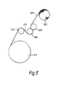
- FIG. 3 shows the general arrangement of the apparatus.
- 200 is the dispenser which dispenses film 204 from a roll thereof.
- 206, 208 and 212 comprise rollers of a film feeder, of which rollers 208 and 212 constitute stretch roller means, the latter (212) being rotated at a higher peripheral speed than the former (208) to stretch the film 210 therebetween.
- the ensuring stretched film 210 is used to wrap the object shown as bale 214.
- the invention is applicable to the wrapping of objects with a stretched wrapping film, more particularly to the wrapping of agricultural products.
- the invention is especially suited for the wrapping of bundles of silage.
Landscapes
- Engineering & Computer Science (AREA)
- Mechanical Engineering (AREA)
- Storage Of Harvested Produce (AREA)
- Basic Packing Technique (AREA)
- Containers And Plastic Fillers For Packaging (AREA)
- Supplying Of Containers To The Packaging Station (AREA)
- Shaping By String And By Release Of Stress In Plastics And The Like (AREA)
Claims (13)
- Vorrichtung zur Umhüllung oder Verkapselung eines Gegenstands, wie eines Silofutterballens (214), mit jeglicher Form oder Art streckbarer Polymerfolie (204), die einen Folienabrollapparat (200) mit Streckwalzenmitteln (208, 212) zum Strecken der Folie (204), einen Folienzufuhrapparat (206, 208) zur Zuführung der Folie zu den Streckwalzenmitteln (208, 212), Mittel (12) zum Antrieb der Streckwalzenmittel (208, 212), um die Folie (204) zu strecken, und Mittel (14) zum Drehen des Gegenstands (214) zur Aufnahme der gestreckten Folie (210) von den Streckwalzenmitteln (208, 212) umfaßt, dadurch gekennzeichnet, daß das Mittel zum Antrieb der besagten Streckwalzenmittel (208, 212) des Abrollapparates (200) einen oder mehrere erste(n) Hydraulikmotor(en) (12) umfaßt, die teilweise oder ganz in einem seriellen Hydraulikkreis mit einem oder mehreren zweiten Hydraulikmotor(en) (14) zur Drehung des Gegenstands (214) verbunden ist, wodurch der oder die verwendete(n) zweite(n) Hydraulikmotor(en) (14) angetrieben werden und teilweise oder ganz mit dem Ölstrom von dem oder den ersten Hydraulikmotor(en) (12) laufen und wodurch ein gewünschtes Verhältnis der Leistung des ersten Hydraulikmotors oder der ersten Hydraulikmotoren (12) zu der Leistung des zweiten Hydraulikmotors oder der zweiten Hydraulikmotoren (14) aufrechterhalten werden kann.
- Vorrichtung nach Anspruch 1, bei der das Streckwalzenmittel (208, 212) mindestens zwei Walzen umfaßt, die mit geeigneter/geeigneten Umfangsgeschwindigkeit(en) gedreht werden, um das gewünschte Streckungsverhältnis zu erreichen.
- Vorrichtung zur Umhüllung oder Verkapselung eines Gegenstands, wie eines Silofutterballens (214), mit jeglicher Form oder Art streckbarer Polymerfolie (204), die einen Folienabrollapparat (200) mit einer oder mehreren Streckwalzen (208, 212) zum Strecken der Folie (204), einen Folienzufuhrapparat (206, 208) zur Zuführung der Folie zu der/den Streckwalze(n) (208, 212), Mittel (12) zum Drehen der Streckwalze (208, 212) oder mindestens einer von ihnen, um die Folie (204) zu strecken, und Antriebsmittel (14) zur Bewegung des Abrollapparates (200) in einer oder mehreren Achsen um den Gegenstand (214) umfaßt, um eine Folienhülle an dem Gegenstand anzubringen, dadurch gekennzeichnet, daß das Rotationsmittel der Walze einen oder mehrere erste(n) Hydraulikmotor(en) (12) umfaßt, der/die teilweise oder ganz in einem seriellen Hydraulikkreis mit einem oder mehreren Hydraulikmotor(en) (14) verbunden ist/sind, der/die das besagte Antriebsmittel bildet/bilden, durch das der oder die verwendete(n) zweite Hydraulikmotor(en) (14) betrieben wird/werden und durch das ein gewünschtes Verhältnis der Leistung des ersten Hydraulikmotors oder der ersten Hydraulikmotoren (12) zu der Leistung des zweiten Hydraulikmotors oder der zweiten Hydraulikmotoren (14) aufrechterhalten werden kann.
- Vorrichtung nach einem der Ansprüche 1 bis 3, bei der der/die erste(n) Motor(en) (12) mit oder ohne Online- oder Offline-Durchflußregelventile (20) oder Geräte bereitgestellt werden, und ebenso der/die zweite(n) Motor(en) (14).
- Vorrichtung nach einem der Ansprüche 1 bis 3, bei der der/die zweite(n) Motor(n) (14) so angeschlossen ist/sind, daß er/sie Öl ausschließlich von dem Auspuff (12b, 52) des ersten Motors/der ersten Motoren oder teilweise von dem besagten Auspuff (12b, 52) und teilweise von einer Ölzuleitung (32, 24) vor dem/den ersten Motor(en) (12) über eine vorzugsweise einstellbare Entnahmeleitung (32, 20, 24) erhält/erhalten.
- Vorrichtung nach einem der vorstehenden Ansprüche, bei der der Folienzufuhrapparat zwei Quetschwalzen (206, 208) umfaßt und die zweite Quetschwalze (208) direkt von dem zweiten Motor (14) angetrieben und mit der ersten Quetschwalze (206) verzahnt ist, um sie mit derselben Umfangsgeschwindigkeit anzutreiben.
- Vorrichtung nach Anspruch 6, bei der die Streckwalze (208), die eine der beiden Quetschwalzen (206, 208) darstellt, mit der anderen Streckwalze (212) verzahnt ist, um letztere mit mindestens 55 % bis 70 % höherer Umfangsgeschwindigkeit und vorzugsweise bis zu 160 % höherer Umfangsgeschwindigkeit als die besagte Streckwalze (208) anzutreiben.
- Vorrichtung laut einem der vorhergehenden Ansprüche, die weiterhin hydraulische Regelmittel (64) zur Bewirkung einer Umsteuerung des zweiten Motors/der zweiten Motoren (14) umfaßt.
- Vorrichtung laut einem der vorstehenden Ansprüche, die weiterhin hydraulische Regelmittel (20) zur Regelung der Drehzahl des ersten Motors/der ersten Motoren (12) umfaßt.
- Ein Verfahren zur Umhüllung eines Gegenstands (214), wie eines Silofutterballens, mit Folie (204), das die Zuführung der Folie (204) von einem Abrollapparat (200) zu dem Gegenstand (214) über ein Paar motorisch betriebene Streckwalzen (208, 212) bei gleichzeitiger Drehung des Gegenstands (214) mittels eines Motors umfaßt, dadurch gekennzeichnet, daß die Streckwalzen (208, 212) durch mindestens einen ersten Hydraulikmotor (12) angetrieben werden und daß mindestens ein zweiter Hydraulikmotor (14) für die Drehung des Gegenstands verwendet wird, wobei der erste Motor (12) in Serie mit dem zweiten Motor (14) verbunden ist, wodurch letzterer ganz oder teilweise mit dem Abgas (12b, 52) des ersten Motors (12) betrieben wird, wodurch ein gewünschtes Verhältnis der Leistungen der ersten und zweiten Motoren (12, 14) aufrechterhalten werden kann.
- Ein Verfahren zur Umhüllung eines Gegenstands (214) , wie eines Silofutterballens, mit Folie (204), das die Zuführung der Folie (204) von einem Abrollapparat (200) zu dem Gegenstand (214) über ein Paar Streckwalzen (208, 212), die Bewegung des Abrollapparates (200) um den Gegenstand in einer oder mehreren Achsen und den Betrieb zweier hydraulischer Motormittel (12, 14) zum Strecken der Folie (204) und Bewegen des Abrollapparates (200) umfaßt, dadurch gekennzeichnet, daß mindestens ein erster Hydraulikmotor (12) zum Antrieb der Streckwalzen (208, 212) verwendet wird und mindestens ein zweiter Motor (14) zur Bewegung des Abrollapparates (200) verwendet wird, wobei die Motoren (12, 14) in Serie verbunden sind und der zweite Motor (14) ganz oder teilweise mit dem Abgas (12b, 52) des ersten Motors (12) angetrieben und betrieben wird, wodurch ein gewünschtes Verhältnis der Leistungen der ersten und zweiten Motoren (12, 14) aufrechterhalten werden kann.
- Ein Verfahren nach Anspruch 10 oder Anspruch 11, bei dem eine der Streckwalzen (208) eine der beiden Quetschwalzen (206, 208) darstellt und direkt von dem ersten Motor (12) angetrieben wird und mit der anderen Quetschwalze (206) verzahnt ist, um sie mit derselben Umfangsgeschwindigkeit anzutreiben.
- Ein Verfahren nach Anspruch 10 oder Anspruch 11, bei dem die Streckwalze (208), die eine der beiden Quetschwalzen darstellt, mit der anderen Streckwalze (212) verzahnt ist, um letztere mit mindestens 55 % bis 70 % höherer Umfangsgeschwindigkeit und vorzugsweise bis zu 160 % höherer Umfangsgeschwindigkeit zu betreiben als die besagte Streckwalze (208).
Applications Claiming Priority (3)
| Application Number | Priority Date | Filing Date | Title |
|---|---|---|---|
| GB9512281 | 1995-06-16 | ||
| GBGB9512281.8A GB9512281D0 (en) | 1995-06-16 | 1995-06-16 | Improved wrapping methods and apparatus |
| PCT/GB1996/001458 WO1997000202A1 (en) | 1995-06-16 | 1996-06-17 | Improved wrapping methods and apparatus |
Publications (2)
| Publication Number | Publication Date |
|---|---|
| EP0833773A1 EP0833773A1 (de) | 1998-04-08 |
| EP0833773B1 true EP0833773B1 (de) | 2000-03-29 |
Family
ID=10776194
Family Applications (1)
| Application Number | Title | Priority Date | Filing Date |
|---|---|---|---|
| EP96918753A Expired - Lifetime EP0833773B1 (de) | 1995-06-16 | 1996-06-17 | Verbessertes umhüllungsverfahren und vorrichtung |
Country Status (11)
| Country | Link |
|---|---|
| US (1) | US5979146A (de) |
| EP (1) | EP0833773B1 (de) |
| AT (1) | ATE191195T1 (de) |
| AU (1) | AU704734B2 (de) |
| DE (1) | DE69607467T2 (de) |
| DK (1) | DK0833773T3 (de) |
| ES (1) | ES2146885T3 (de) |
| GB (1) | GB9512281D0 (de) |
| NZ (1) | NZ310504A (de) |
| PT (1) | PT833773E (de) |
| WO (1) | WO1997000202A1 (de) |
Families Citing this family (23)
| Publication number | Priority date | Publication date | Assignee | Title |
|---|---|---|---|---|
| GB9626234D0 (en) * | 1996-12-18 | 1997-02-05 | Mobil Plastics Europ Inc | Wrapping apparatus |
| IES81095B2 (en) | 1998-06-05 | 2000-03-08 | Arboc Limited | A bale wrapping machine |
| JP2011509220A (ja) | 2008-01-07 | 2011-03-24 | ランテク ドット コム,リミティド ライアビリティ カンパニー | 包装装置における計量フィルム供給の電子制御 |
| US9908648B2 (en) | 2008-01-07 | 2018-03-06 | Lantech.Com, Llc | Demand based wrapping |
| ATE503377T1 (de) * | 2008-04-02 | 2011-04-15 | Deere & Co | Ballenumhüllvorrichtung |
| AU2011320322B2 (en) | 2010-10-29 | 2016-06-09 | Lantech.Com, Llc | Machine generated wrap data |
| CA2889579C (en) | 2012-10-25 | 2020-07-14 | Lantech.Com, Llc | Corner geometry-based wrapping |
| EP2917112B1 (de) | 2012-10-25 | 2017-06-28 | Lantech.Com LLC | Drehungswinkelbasierte wicklung |
| CA3109066C (en) | 2012-10-25 | 2023-03-07 | Lantech.Com, Llc | Effective circumference-based wrapping |
| EP3301032B1 (de) | 2013-02-13 | 2019-05-01 | Lantech.Com LLC | Umfassungskraftbasiertes umwickeln |
| EP4332009A3 (de) | 2014-01-14 | 2024-10-09 | Lantech.com, LLC | Dynamische anpassung von auf überwachte hüllkraft reagierenden hüllkraftparametern und/oder zur filmbruchreduktion |
| CA2975347C (en) | 2014-10-07 | 2020-02-11 | Lantech.Com, Llc | Graphical depiction of wrap profile for load wrapping apparatus |
| US10440895B2 (en) * | 2015-08-17 | 2019-10-15 | Deere & Company | Motor-drive for application of wrap material to crop packages |
| AU2016326540B2 (en) | 2015-09-25 | 2019-07-25 | Lantech.Com, Llc | Stretch wrapping machine with automated determination of load stability by subjecting a load to a disturbance |
| GB2552214A (en) * | 2016-07-14 | 2018-01-17 | Kuhn-Geldrop Bv | Bale wrapper and method of applying stretch film wrapping to an agricultural bale |
| US10827685B2 (en) * | 2017-08-11 | 2020-11-10 | Vermeer Manufacturing Company | Hydraulic brake for wrap material |
| AU2018338049B2 (en) | 2017-09-22 | 2021-12-23 | Lantech.Com, Llc | Load wrapping apparatus wrap profiles with controlled wrap cycle interruptions |
| AU2019319726B2 (en) | 2018-08-06 | 2022-04-07 | Lantech.Com, Llc | Stretch wrapping machine with curve fit control of dispense rate |
| US20210022295A1 (en) * | 2019-07-22 | 2021-01-28 | Cnh Industrial America Llc | Agricultural baler with passive spreader roll assembly |
| US11479378B2 (en) | 2019-09-09 | 2022-10-25 | Lantech.Com, Llc | Stretch wrapping machine with dispense rate control based on sensed rate of dispensed packaging material and predicted load geometry |
| AU2020350496B2 (en) | 2019-09-19 | 2024-01-25 | Lantech.Com, Llc | Packaging material grading and/or factory profiles |
| WO2023235698A1 (en) | 2022-06-03 | 2023-12-07 | Signode Industrial Group Llc | Stretch-wrapping machine with pre-stretch rollers |
| CN116767559B (zh) * | 2023-08-04 | 2026-01-06 | 广东金昇智能数控有限公司 | 一种用于reel包装盘保护带包装的转动压夹机构 |
Family Cites Families (6)
| Publication number | Priority date | Publication date | Assignee | Title |
|---|---|---|---|---|
| GB2159489B (en) * | 1984-05-25 | 1989-04-05 | Eight Milieu Nominees Pty Ltd | Silage production |
| EP0242975A3 (de) * | 1986-03-22 | 1988-03-09 | Gerald Vennall | Umwickelmaschine |
| US4817127A (en) * | 1986-08-08 | 1989-03-28 | Dictaphone Corporation | Modular dictation/transcription system |
| SE467248B (sv) * | 1991-04-08 | 1992-06-22 | Staffan Ragnar Soederberg | Foerfarande och anordning foer emballering av balar daer foerpackningsfilm aeven paafoers i korsande riktning |
| GB2275905A (en) * | 1993-03-12 | 1994-09-14 | Kenneth Stephen Eddin Orpen | Hydraulic bale wrapper |
| US5483785A (en) * | 1994-06-17 | 1996-01-16 | Dicarlo Machine Corporation | Apparatus for wrapping bales of silage |
-
1995
- 1995-06-16 GB GBGB9512281.8A patent/GB9512281D0/en active Pending
-
1996
- 1996-06-17 ES ES96918753T patent/ES2146885T3/es not_active Expired - Lifetime
- 1996-06-17 NZ NZ310504A patent/NZ310504A/xx unknown
- 1996-06-17 EP EP96918753A patent/EP0833773B1/de not_active Expired - Lifetime
- 1996-06-17 DK DK96918753T patent/DK0833773T3/da active
- 1996-06-17 WO PCT/GB1996/001458 patent/WO1997000202A1/en not_active Ceased
- 1996-06-17 PT PT96918753T patent/PT833773E/pt unknown
- 1996-06-17 DE DE69607467T patent/DE69607467T2/de not_active Expired - Fee Related
- 1996-06-17 US US08/981,183 patent/US5979146A/en not_active Expired - Fee Related
- 1996-06-17 AT AT96918753T patent/ATE191195T1/de not_active IP Right Cessation
- 1996-06-17 AU AU61309/96A patent/AU704734B2/en not_active Ceased
Also Published As
| Publication number | Publication date |
|---|---|
| DE69607467D1 (de) | 2000-05-04 |
| NZ310504A (en) | 1999-07-29 |
| AU6130996A (en) | 1997-01-15 |
| AU704734B2 (en) | 1999-04-29 |
| PT833773E (pt) | 2000-09-29 |
| ES2146885T3 (es) | 2000-08-16 |
| GB9512281D0 (en) | 1995-08-16 |
| WO1997000202A1 (en) | 1997-01-03 |
| DE69607467T2 (de) | 2000-11-16 |
| US5979146A (en) | 1999-11-09 |
| DK0833773T3 (da) | 2000-09-04 |
| EP0833773A1 (de) | 1998-04-08 |
| ATE191195T1 (de) | 2000-04-15 |
Similar Documents
| Publication | Publication Date | Title |
|---|---|---|
| EP0833773B1 (de) | Verbessertes umhüllungsverfahren und vorrichtung | |
| JP3604140B2 (ja) | 梱の油圧式梱包装置 | |
| US6253532B1 (en) | Wrapping apparatus | |
| US8276346B2 (en) | Wrapping apparatus and method including metered pre-stretch film delivery assembly | |
| WO1994020367A9 (en) | Hydraulic bale wrapper | |
| US4862678A (en) | Constant tension stretch wrapping machine | |
| US4590746A (en) | Constant tension stretch wrapping machine | |
| EP2816887B1 (de) | Verfahren und system zur steuerung der umhüllung eines zylindrischen ballens in der ballenformungskammer einer ballenpresse sowie ballenpresse und verfahren zur herstellung eines umhüllten ballens | |
| EP0842850A3 (de) | Vorrichtung und Verfahren zum Umhüllen einer Ladung mit Steuerung der Umhüllungsspannung | |
| US5581979A (en) | Method and apparatus for applying a constant tension to a film | |
| US4706443A (en) | Constant tension stretch wrapping machine | |
| US4658570A (en) | Wood bundling device | |
| EP0242975A2 (de) | Umwickelmaschine | |
| US7347035B2 (en) | Assembly for automatically unrolling and cutting stretch film |
Legal Events
| Date | Code | Title | Description |
|---|---|---|---|
| PUAI | Public reference made under article 153(3) epc to a published international application that has entered the european phase |
Free format text: ORIGINAL CODE: 0009012 |
|
| 17P | Request for examination filed |
Effective date: 19971223 |
|
| AK | Designated contracting states |
Kind code of ref document: A1 Designated state(s): AT BE CH DE DK ES FI FR GB IE IT LI LU NL PT SE |
|
| RBV | Designated contracting states (corrected) |
Designated state(s): AT BE CH DE DK ES FI FR GB IE IT LI LU NL PT SE |
|
| 17Q | First examination report despatched |
Effective date: 19980515 |
|
| GRAG | Despatch of communication of intention to grant |
Free format text: ORIGINAL CODE: EPIDOS AGRA |
|
| GRAG | Despatch of communication of intention to grant |
Free format text: ORIGINAL CODE: EPIDOS AGRA |
|
| GRAG | Despatch of communication of intention to grant |
Free format text: ORIGINAL CODE: EPIDOS AGRA |
|
| GRAH | Despatch of communication of intention to grant a patent |
Free format text: ORIGINAL CODE: EPIDOS IGRA |
|
| RAP1 | Party data changed (applicant data changed or rights of an application transferred) |
Owner name: ITW MIMA FILMS LLC Owner name: ORPEN, KENNETH STEPHEN EDDIN |
|
| GRAH | Despatch of communication of intention to grant a patent |
Free format text: ORIGINAL CODE: EPIDOS IGRA |
|
| GRAA | (expected) grant |
Free format text: ORIGINAL CODE: 0009210 |
|
| AK | Designated contracting states |
Kind code of ref document: B1 Designated state(s): AT BE CH DE DK ES FI FR GB IE IT LI LU NL PT SE |
|
| REF | Corresponds to: |
Ref document number: 191195 Country of ref document: AT Date of ref document: 20000415 Kind code of ref document: T |
|
| REG | Reference to a national code |
Ref country code: CH Ref legal event code: EP |
|
| REG | Reference to a national code |
Ref country code: IE Ref legal event code: FG4D |
|
| REF | Corresponds to: |
Ref document number: 69607467 Country of ref document: DE Date of ref document: 20000504 |
|
| ITF | It: translation for a ep patent filed | ||
| REG | Reference to a national code |
Ref country code: CH Ref legal event code: NV Representative=s name: PATENTANWAELTE SCHAAD, BALASS, MENZL & PARTNER AG |
|
| ET | Fr: translation filed | ||
| REG | Reference to a national code |
Ref country code: ES Ref legal event code: FG2A Ref document number: 2146885 Country of ref document: ES Kind code of ref document: T3 |
|
| REG | Reference to a national code |
Ref country code: DK Ref legal event code: T3 |
|
| REG | Reference to a national code |
Ref country code: PT Ref legal event code: SC4A Free format text: AVAILABILITY OF NATIONAL TRANSLATION Effective date: 20000626 |
|
| PLBE | No opposition filed within time limit |
Free format text: ORIGINAL CODE: 0009261 |
|
| STAA | Information on the status of an ep patent application or granted ep patent |
Free format text: STATUS: NO OPPOSITION FILED WITHIN TIME LIMIT |
|
| 26N | No opposition filed | ||
| REG | Reference to a national code |
Ref country code: GB Ref legal event code: IF02 |
|
| PGFP | Annual fee paid to national office [announced via postgrant information from national office to epo] |
Ref country code: ES Payment date: 20080626 Year of fee payment: 13 Ref country code: CH Payment date: 20080630 Year of fee payment: 13 |
|
| PGFP | Annual fee paid to national office [announced via postgrant information from national office to epo] |
Ref country code: AT Payment date: 20080603 Year of fee payment: 13 |
|
| PGFP | Annual fee paid to national office [announced via postgrant information from national office to epo] |
Ref country code: FI Payment date: 20080630 Year of fee payment: 13 Ref country code: PT Payment date: 20080604 Year of fee payment: 13 |
|
| PGFP | Annual fee paid to national office [announced via postgrant information from national office to epo] |
Ref country code: NL Payment date: 20080624 Year of fee payment: 13 Ref country code: LU Payment date: 20080702 Year of fee payment: 13 Ref country code: IE Payment date: 20080627 Year of fee payment: 13 Ref country code: DK Payment date: 20080626 Year of fee payment: 13 Ref country code: DE Payment date: 20080731 Year of fee payment: 13 |
|
| PGFP | Annual fee paid to national office [announced via postgrant information from national office to epo] |
Ref country code: FR Payment date: 20080617 Year of fee payment: 13 |
|
| PGFP | Annual fee paid to national office [announced via postgrant information from national office to epo] |
Ref country code: GB Payment date: 20080627 Year of fee payment: 13 |
|
| PGFP | Annual fee paid to national office [announced via postgrant information from national office to epo] |
Ref country code: SE Payment date: 20080627 Year of fee payment: 13 Ref country code: BE Payment date: 20080730 Year of fee payment: 13 |
|
| PGFP | Annual fee paid to national office [announced via postgrant information from national office to epo] |
Ref country code: IT Payment date: 20081211 Year of fee payment: 13 |
|
| REG | Reference to a national code |
Ref country code: PT Ref legal event code: MM4A Free format text: LAPSE DUE TO NON-PAYMENT OF FEES Effective date: 20091217 |
|
| BERE | Be: lapsed |
Owner name: *ITW MIMA FILMS LLC Effective date: 20090630 Owner name: *ORPEN KENNETH STEPHEN EDDIN Effective date: 20090630 |
|
| PG25 | Lapsed in a contracting state [announced via postgrant information from national office to epo] |
Ref country code: FI Free format text: LAPSE BECAUSE OF NON-PAYMENT OF DUE FEES Effective date: 20090617 |
|
| REG | Reference to a national code |
Ref country code: CH Ref legal event code: PL |
|
| REG | Reference to a national code |
Ref country code: DK Ref legal event code: EBP |
|
| GBPC | Gb: european patent ceased through non-payment of renewal fee |
Effective date: 20090617 |
|
| NLV4 | Nl: lapsed or anulled due to non-payment of the annual fee |
Effective date: 20100101 |
|
| REG | Reference to a national code |
Ref country code: FR Ref legal event code: ST Effective date: 20100226 |
|
| PG25 | Lapsed in a contracting state [announced via postgrant information from national office to epo] |
Ref country code: PT Free format text: LAPSE BECAUSE OF NON-PAYMENT OF DUE FEES Effective date: 20091217 |
|
| REG | Reference to a national code |
Ref country code: IE Ref legal event code: MM4A |
|
| PG25 | Lapsed in a contracting state [announced via postgrant information from national office to epo] |
Ref country code: LI Free format text: LAPSE BECAUSE OF NON-PAYMENT OF DUE FEES Effective date: 20090630 Ref country code: IE Free format text: LAPSE BECAUSE OF NON-PAYMENT OF DUE FEES Effective date: 20090617 Ref country code: FR Free format text: LAPSE BECAUSE OF NON-PAYMENT OF DUE FEES Effective date: 20090630 Ref country code: CH Free format text: LAPSE BECAUSE OF NON-PAYMENT OF DUE FEES Effective date: 20090630 |
|
| PG25 | Lapsed in a contracting state [announced via postgrant information from national office to epo] |
Ref country code: GB Free format text: LAPSE BECAUSE OF NON-PAYMENT OF DUE FEES Effective date: 20090617 |
|
| PG25 | Lapsed in a contracting state [announced via postgrant information from national office to epo] |
Ref country code: DE Free format text: LAPSE BECAUSE OF NON-PAYMENT OF DUE FEES Effective date: 20100101 Ref country code: BE Free format text: LAPSE BECAUSE OF NON-PAYMENT OF DUE FEES Effective date: 20090630 Ref country code: AT Free format text: LAPSE BECAUSE OF NON-PAYMENT OF DUE FEES Effective date: 20090617 |
|
| PG25 | Lapsed in a contracting state [announced via postgrant information from national office to epo] |
Ref country code: NL Free format text: LAPSE BECAUSE OF NON-PAYMENT OF DUE FEES Effective date: 20100101 Ref country code: DK Free format text: LAPSE BECAUSE OF NON-PAYMENT OF DUE FEES Effective date: 20090630 |
|
| REG | Reference to a national code |
Ref country code: ES Ref legal event code: FD2A Effective date: 20090618 |
|
| PG25 | Lapsed in a contracting state [announced via postgrant information from national office to epo] |
Ref country code: ES Free format text: LAPSE BECAUSE OF NON-PAYMENT OF DUE FEES Effective date: 20090618 |
|
| PG25 | Lapsed in a contracting state [announced via postgrant information from national office to epo] |
Ref country code: IT Free format text: LAPSE BECAUSE OF NON-PAYMENT OF DUE FEES Effective date: 20090617 |
|
| PG25 | Lapsed in a contracting state [announced via postgrant information from national office to epo] |
Ref country code: LU Free format text: LAPSE BECAUSE OF NON-PAYMENT OF DUE FEES Effective date: 20090617 |
|
| PG25 | Lapsed in a contracting state [announced via postgrant information from national office to epo] |
Ref country code: SE Free format text: LAPSE BECAUSE OF NON-PAYMENT OF DUE FEES Effective date: 20090618 |