EP0833216A2 - Registration of color images - Google Patents
Registration of color images Download PDFInfo
- Publication number
- EP0833216A2 EP0833216A2 EP97307396A EP97307396A EP0833216A2 EP 0833216 A2 EP0833216 A2 EP 0833216A2 EP 97307396 A EP97307396 A EP 97307396A EP 97307396 A EP97307396 A EP 97307396A EP 0833216 A2 EP0833216 A2 EP 0833216A2
- Authority
- EP
- European Patent Office
- Prior art keywords
- black
- image
- color
- boundary
- toner
- Prior art date
- Legal status (The legal status is an assumption and is not a legal conclusion. Google has not performed a legal analysis and makes no representation as to the accuracy of the status listed.)
- Withdrawn
Links
Images


Classifications
-
- G—PHYSICS
- G03—PHOTOGRAPHY; CINEMATOGRAPHY; ANALOGOUS TECHNIQUES USING WAVES OTHER THAN OPTICAL WAVES; ELECTROGRAPHY; HOLOGRAPHY
- G03G—ELECTROGRAPHY; ELECTROPHOTOGRAPHY; MAGNETOGRAPHY
- G03G13/00—Electrographic processes using a charge pattern
- G03G13/01—Electrographic processes using a charge pattern for multicoloured copies
-
- H—ELECTRICITY
- H04—ELECTRIC COMMUNICATION TECHNIQUE
- H04N—PICTORIAL COMMUNICATION, e.g. TELEVISION
- H04N1/00—Scanning, transmission or reproduction of documents or the like, e.g. facsimile transmission; Details thereof
- H04N1/46—Colour picture communication systems
- H04N1/56—Processing of colour picture signals
- H04N1/58—Edge or detail enhancement; Noise or error suppression, e.g. colour misregistration correction
-
- G—PHYSICS
- G03—PHOTOGRAPHY; CINEMATOGRAPHY; ANALOGOUS TECHNIQUES USING WAVES OTHER THAN OPTICAL WAVES; ELECTROGRAPHY; HOLOGRAPHY
- G03G—ELECTROGRAPHY; ELECTROPHOTOGRAPHY; MAGNETOGRAPHY
- G03G2215/00—Apparatus for electrophotographic processes
- G03G2215/01—Apparatus for electrophotographic processes for producing multicoloured copies
- G03G2215/0167—Apparatus for electrophotographic processes for producing multicoloured copies single electrographic recording member
- G03G2215/017—Apparatus for electrophotographic processes for producing multicoloured copies single electrographic recording member single rotation of recording member to produce multicoloured copy
Definitions
- This invention relates generally to the registration of color images in a color image output terminal (IOT), and more particularly concerns an improved color image alignment system utilizing an improved method for providing optimum optical contrast for detecting registration marks in full color electrophotographic printing machines.
- IOT color image output terminal
- a photoconductive member is charged to a substantially uniform potential so as to sensitize the surface thereof.
- the charged portion of the photoconductive member is exposed to a light image of an original document being reproduced. Exposure of the charged photoconductive member selectively dissipates the charges thereon in the irradiated areas.
- the latent image is developed by bringing a developer material into contact therewith.
- the developer material comprises toner particles adhering triboelectrically to carrier granules.
- the toner particles are attracted from the carrier granules to the latent image forming a toner powder image on the photoconductive member.
- the toner powder image is then transferred from the photoconductive member to a copy sheet.
- the toner particles are heated to permanently affix the powder image to the copy sheet.
- the foregoing generally describes a typical black and white electrophotographic printing machine.
- an architecture which comprises a plurality of image forming stations.
- One example of the plural image forming station architecture utilizes an image on image system in which the photoreceptive member is recharged, reimaged and developed for each color separation.
- This charging, imaging, developing and recharging, reimaging and developing (REaD-Recharge, Expose and Develop) is usually done in a single revolution of the photoreceptor as compared with multipass architectures which allow image on image to be achieved with a single charge, recharge system and imager, etc.
- This architecture offers a high potential for throughput and image quality.
- Halo is a term used to describe a thin white line next to a feature of one color where it is supposed to be printed adjacent to another color. This is particularly objectionable when the halo completely surrounds black text in a color background or color text in a black background. This effect is difficult at best to remove by improvements in the physical process.
- This invention proposes to use a variety of image processing algorithms to minimize the visual impact of halo.
- Trapping is a process that is known for correcting non-filled or white areas between different color separations in a color print.
- this approach involves expanding one of the regions which abut so as to fill the gap or misregistered border with a color so as to minimize the visual effect.
- the border that has been so expanded is referred to as a "trap” and the zone within which the color is added is called the "trap zone". Examples of such methods are given in US-A-4 583 116; US-A-4 700 399; US-A-4 931 861; US-A-5 204 918; US-A-5 241 396; US-A-5 386 223 and US-A-5 313 570.
- a method for mitigating visual halo effect in an electrophotographic color printing machine comprising determining the boundary between a black pixel and a non-black pixel and printing a boundary black pixel using process black as a combination of cyan, magenta and yellow toner particles.
- the electrophotographic printing machine of the present invention uses a charge retentive surface in the form of an Active Matrix (AMAT) photoreceptor belt 10 supported for movement in the direction indicated by arrow 12, for advancing sequentially through the various xerographic process stations.
- the belt 10 is entrained about a drive roller 14 and two tension rollers 16 and 18 and the roller 14 is operatively connected to a drive motor (not shown) for effecting movement of the belt through the xerographic stations.
- AMAT Active Matrix
- a portion of belt 10 passes through charging station A where a corona generating device, indicated generally by the reference numeral 22, charges the photoconductive surface of belt 10 to a relative high, substantially uniform, preferably negative potential.
- a controller receives the image signals representing the desired output image and processes these signals to convert them to the various color separations of the image which is transmitted to a laser based output scanning device 38 which causes the charge retentive surface to be discharged in accordance with the output from the scanning device.
- the scanning device is a laser Raster Output Scanner (ROS).
- ROS Raster Output Scanner
- the ROS could be replaced by other xerographic exposure devices such as LED arrays.
- the photoreceptor belt 10 which is initially charged to a voltage V o , undergoes dark decay to a level Vddp equal to about -500V. When exposed at the exposure station it is discharged to V background equal to about -50V. Thus after exposure, the photoreceptor belt 10 contains a monopolar voltage profile of high and low voltages, the former corresponding to charged areas and the latter corresponding to discharged or background areas.
- a magnetic brush developer structure indicated generally by the reference numeral 26 advances insulative magnetic brush (IMB) material into contact with the electrostatic latent image.
- the development structure 26 comprises a plurality of magnetic brush roller members. These magnetic brush rollers present, for example, charged black toner material to the image areas for development thereof. Appropriate developer biasing is accomplished via a power supply (not shown).
- a corona recharge device 36 having a high output current vs. control surface voltage (I/V) characteristic slope is employed for raising the voltage level of both the toned and untoned areas on the photoreceptor belt 10 to a substantially uniform level.
- the recharging device 36 serves to recharge the photoreceptor belt 10 to a predetermined level.
- a second exposure or imaging device 38 which may comprise a laser based output structure is utilized for selectively discharging the photoreceptor belt 10 on toned areas and/or bare areas, pursuant to the image to be developed with the second color developer.
- the photoreceptor belt 10 contains toned and untoned areas at relatively high voltage levels and toned and untoned areas at relatively low voltage levels. These low voltage areas represent image areas which are developed using discharged area development (DAD).
- DAD discharged area development
- a negatively charged, developer material (not shown) comprising color toner is employed.
- the toner which by way of example may be yellow, is contained in a developer housing structure 42 disposed at a second developer station and is presented to the latent images on the photoreceptor belt 10 by way of a magnetic brush roller and a non-contacting donor roller to create a toner powder cloud.
- a power supply (not shown) serves to electrically bias the developer structure to a level effective to develop the DAD image areas with negatively charged yellow toner particles.
- the above procedure is repeated for a third imager for a third suitable color toner such as magenta and for a fourth imager and suitable color toner such as cyan. In this manner a full color composite toner image is developed on the photoreceptor belt.
- the third and fourth imaging and developer stations are identical, except for the color of the toner particles, to the second station and are therefore numbered the same.
- a negative pre-transfer dicorotron member 50 is provided to condition the toner for effective transfer to a substrate using positive corona discharge.
- a sheet of support material 52 is moved into contact with the toner images at transfer station C.
- the sheet of support material is advanced to transfer station by conventional sheet feeding apparatus, not shown.
- the sheet feeding apparatus includes a feed roll contacting the uppermost sheet of a stack copy sheets. The feed rolls rotate so as to advance the uppermost sheet from stack into a chute which directs the advancing sheet of support material into contact with photoconductive surface of belt 10 in a timed sequence so that the toner powder image developed thereon contacts the advancing sheet of support material at transfer station.
- the transfer station C includes a transfer dicorotron 54 which sprays positive ions onto the backside of sheet 52. This attracts the negatively charged toner powder images from the belt 10 to sheet 52.
- a detack dicorotron 56 is provided for facilitating stripping of the sheets from the belt 10.
- the fusing station D includes a fuser assembly, indicated generally by the reference numeral 60, which permanently affixes the transferred powder image to sheet 52.
- fuser assembly 60 comprises a heated fuser roller 62 and a backup or pressure roller 64.
- Sheet 52 passes between fuser roller 62 and backup roller 64 with the toner powder image contacting fuser roller 62.
- a chute guides the advancing sheets 52 to a finishing device or catch tray, not shown, for subsequent removal from the printing machine by the operator.
- the residual toner particles carried by the non-image areas on the photoconductive surface are removed therefrom. These particles are removed at a cleaning station E using a cleaning brush structure contained in a housing 66 and cleaning blade 67.
- the blade may be configured in either a wiper or doctor position depending on the application.
- a discharge lamp (not shown) floods photoconductive surface 10 with light to dissipate any residual electrostatic charge remaining thereon prior to the charging thereof for the next successive imaging cycle.
- color printing is carried out by using four colorants, cyan, magenta, yellow, and black.
- the colorants are applied in separate stages and this can lead to problems if the registration between each color separation is not precise.
- This problem can also occur for black text on a cyan background, or more generally at the boundary between any two color separations (e.g. red and green, or magenta and cyan).
- a cyan background or more generally at the boundary between any two color separations (e.g. red and green, or magenta and cyan).
- one of the colors is black, and an approach that can be used to reduce this problem for this case is to dilate the non-black edge so that it overlaps the black.
- the non-black color will be hidden by the black at the overlap and since the colored area is now larger than the black hole there is room for some registration error before the gap between the toners becomes exposed. This process is an example of trapping.
- nth-bitting One approach to making raster characters look better and to manipulate edges of an image is referred to as "nth-bitting” or partial bitting. These processes turn on selected pixels along the edge of an image or along an image boundary to mesh image portions or to improve the visual characteristics of an image edge or boundary.
- Half-bitting is a subset of "nth-bitting” which turns on an equal number of pixels to those which are turned off.
- Various techniques of halftone processes and "nth-bitting” are described in US-A-4 149 194; US-A-4 808 984; US-A-4 873 515; US-A-4 907 282; US-A-4 918 626; US-A-5 223 953; and US-A-5 333 249.
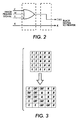
- Figure 2 illustrates a logic circuit for determining a color to black boundary for implementing the method of the invention herein.
- the basis of the boundary determination is to examine a pixel that is next to a black (K) pixel and determine if it is to be printed as a color other than white. If so, then each adjacent, or some function of the total number of adjacent black pixels should be printed using process black.
- FIGS 3, 4 and 5 illustrate various techniques for printing process black pixels next to pixels of other colors according to the invention herein.
- Each of these matrices is illustrative only as there are many other variations possible to balance the competing qualities of edge sharpness versus mitigation of halo effect.
- E(i, j) ⁇ ((C(i+1, j) ⁇ M(i+1, j)) ⁇ (C(i+1, j) ⁇ M(i+1, j) ⁇ Y(i+1, j))) ⁇ ((C(i-1, j) ⁇ M(i-1, j)) ⁇ (C(i-1, j) ⁇ M(i-1, j) ⁇ Y(i-1, j))) ⁇ ((C(i, j+1) ⁇ M(i, j+1)) ⁇ (C(i, j+1) ⁇ M(i, j+1) ⁇ Y(i, j+1))) ⁇ ((C(i, j-1) ⁇ M(i
- a method for mitigating or eliminating a halo effect in a printer when black objects are adjacent color objects In a full color xerographic printer, particularly an image on image printer in which full color composite images are imaged and developed in a single pass through the xerographic system, an image processing method is described to reduce or eliminate the halo effect.
- a black object is to be placed adjacent a colored object (i.e. black text on a magenta background)
- a determination is made to locate the boundary between the black and the colorant.
- the black pixels immediately adjacent the colored objects are created using process black (a combination of cyan, magenta and yellow colorants) while the central and other black areas not adjacent a colored object are created using black toner only.
- process black a combination of cyan, magenta and yellow colorants
Landscapes
- Physics & Mathematics (AREA)
- General Physics & Mathematics (AREA)
- Engineering & Computer Science (AREA)
- Multimedia (AREA)
- Signal Processing (AREA)
- Color Electrophotography (AREA)
- Color Image Communication Systems (AREA)
- Color, Gradation (AREA)
Abstract
Description
Claims (6)
- A method for mitigating visual halo effect in an electrophotographic color printing machine comprising:determining the boundary between a black pixel and a non-black pixel; andprinting a boundary black pixel using process black as a combination of cyan, magenta and yellow toner particles.
- A method according to claim 1, wherein said determining step is limited to determining where said non-black pixel is non-white.
- A method according to claim 2, where said non-black determination ignores the presence or absence of yellow.
- A method according to any one of claims 1 to 3, wherein said printing step further comprises printing only a portion of the boundary black pixels using process black wherein bits to print the portion of process black boundary pixels are chosen as a balancing function between edge sharpness and halo mitigation.
- A method according to claim 4, wherein said balancing function comprises half-bitting.
- A method according to claim 4, wherein said balancing function comprises partial bitting wherein a fraction, f, of the bits on a boundary are made with black toner and the remainder of the boundary bits, 1-f, are made with process black.
Applications Claiming Priority (2)
| Application Number | Priority Date | Filing Date | Title |
|---|---|---|---|
| US72321296A | 1996-09-27 | 1996-09-27 | |
| US723212 | 1996-09-27 |
Publications (2)
| Publication Number | Publication Date |
|---|---|
| EP0833216A2 true EP0833216A2 (en) | 1998-04-01 |
| EP0833216A3 EP0833216A3 (en) | 1999-03-10 |
Family
ID=24905329
Family Applications (1)
| Application Number | Title | Priority Date | Filing Date |
|---|---|---|---|
| EP97307396A Withdrawn EP0833216A3 (en) | 1996-09-27 | 1997-09-22 | Registration of color images |
Country Status (4)
| Country | Link |
|---|---|
| EP (1) | EP0833216A3 (en) |
| JP (1) | JPH10104906A (en) |
| BR (1) | BR9704887A (en) |
| CA (1) | CA2210552C (en) |
Cited By (7)
| Publication number | Priority date | Publication date | Assignee | Title |
|---|---|---|---|---|
| EP1107178A3 (en) * | 1999-11-30 | 2004-02-04 | Xerox Corporation | Gradient-based trapping using patterned trap zones |
| US6856428B1 (en) | 1999-06-10 | 2005-02-15 | Electronics For Imaging, Inc. | Black text printing from page description languages |
| DE102004062841A1 (en) * | 2004-12-27 | 2006-07-13 | OCé PRINTING SYSTEMS GMBH | Method, computer program, computer and printing systems for trapping image data |
| DE102006008768A1 (en) * | 2006-02-24 | 2007-08-30 | OCé PRINTING SYSTEMS GMBH | Print data stream e.g. line condition data stream, processing method, involves storing trapping-information in addition to input data and to data of halftone image for processing as output stream or supplying data of server as output stream |
| EP1947838A3 (en) * | 2007-01-18 | 2009-12-02 | Samsung Electronics Co., Ltd. | Image processing device and method |
| US7817305B2 (en) | 2006-11-24 | 2010-10-19 | Oce Printing Systems Gmbh | Method, computer program and printing system for trapping of print data |
| US8705136B2 (en) | 2006-11-24 | 2014-04-22 | OCé PRINTING SYSTEMS GMBH | Method, computer program and print system for trapping print data |
Families Citing this family (21)
| Publication number | Priority date | Publication date | Assignee | Title |
|---|---|---|---|---|
| US8641644B2 (en) | 2000-11-21 | 2014-02-04 | Sanofi-Aventis Deutschland Gmbh | Blood testing apparatus having a rotatable cartridge with multiple lancing elements and testing means |
| US9427532B2 (en) | 2001-06-12 | 2016-08-30 | Sanofi-Aventis Deutschland Gmbh | Tissue penetration device |
| US9795747B2 (en) | 2010-06-02 | 2017-10-24 | Sanofi-Aventis Deutschland Gmbh | Methods and apparatus for lancet actuation |
| US9226699B2 (en) | 2002-04-19 | 2016-01-05 | Sanofi-Aventis Deutschland Gmbh | Body fluid sampling module with a continuous compression tissue interface surface |
| US7041068B2 (en) | 2001-06-12 | 2006-05-09 | Pelikan Technologies, Inc. | Sampling module device and method |
| US9314194B2 (en) | 2002-04-19 | 2016-04-19 | Sanofi-Aventis Deutschland Gmbh | Tissue penetration device |
| US8784335B2 (en) | 2002-04-19 | 2014-07-22 | Sanofi-Aventis Deutschland Gmbh | Body fluid sampling device with a capacitive sensor |
| US9248267B2 (en) | 2002-04-19 | 2016-02-02 | Sanofi-Aventis Deustchland Gmbh | Tissue penetration device |
| US8579831B2 (en) | 2002-04-19 | 2013-11-12 | Sanofi-Aventis Deutschland Gmbh | Method and apparatus for penetrating tissue |
| US8702624B2 (en) | 2006-09-29 | 2014-04-22 | Sanofi-Aventis Deutschland Gmbh | Analyte measurement device with a single shot actuator |
| US9795334B2 (en) | 2002-04-19 | 2017-10-24 | Sanofi-Aventis Deutschland Gmbh | Method and apparatus for penetrating tissue |
| US7226461B2 (en) | 2002-04-19 | 2007-06-05 | Pelikan Technologies, Inc. | Method and apparatus for a multi-use body fluid sampling device with sterility barrier release |
| US8574895B2 (en) | 2002-12-30 | 2013-11-05 | Sanofi-Aventis Deutschland Gmbh | Method and apparatus using optical techniques to measure analyte levels |
| EP1671096A4 (en) | 2003-09-29 | 2009-09-16 | Pelikan Technologies Inc | METHOD AND APPARATUS FOR AN IMPROVED SAMPLING INTERFERENCE DEVICE |
| EP1680014A4 (en) | 2003-10-14 | 2009-01-21 | Pelikan Technologies Inc | METHOD AND APPARATUS PROVIDING A VARIABLE USER INTERFACE |
| WO2005065414A2 (en) | 2003-12-31 | 2005-07-21 | Pelikan Technologies, Inc. | Method and apparatus for improving fluidic flow and sample capture |
| US8828203B2 (en) | 2004-05-20 | 2014-09-09 | Sanofi-Aventis Deutschland Gmbh | Printable hydrogels for biosensors |
| US9775553B2 (en) | 2004-06-03 | 2017-10-03 | Sanofi-Aventis Deutschland Gmbh | Method and apparatus for a fluid sampling device |
| US20090010562A1 (en) * | 2007-07-03 | 2009-01-08 | Samsung Electronics Co., Ltd. | Method of revising edge region and image forming device using the same |
| US9375169B2 (en) | 2009-01-30 | 2016-06-28 | Sanofi-Aventis Deutschland Gmbh | Cam drive for managing disposable penetrating member actions with a single motor and motor and control system |
| US8965476B2 (en) | 2010-04-16 | 2015-02-24 | Sanofi-Aventis Deutschland Gmbh | Tissue penetration device |
Family Cites Families (9)
| Publication number | Priority date | Publication date | Assignee | Title |
|---|---|---|---|---|
| JP2677283B2 (en) * | 1984-06-14 | 1997-11-17 | キヤノン株式会社 | Color image processing equipment |
| JPS62165475A (en) * | 1986-01-16 | 1987-07-22 | Ricoh Co Ltd | Edge enhancement method for color images |
| JPS63139374A (en) * | 1986-12-02 | 1988-06-11 | Matsushita Electric Ind Co Ltd | Color electrophotographing method |
| JP2693870B2 (en) * | 1991-03-12 | 1997-12-24 | 三田工業株式会社 | Image processing device |
| US5428377A (en) * | 1992-08-11 | 1995-06-27 | Xerox Corporation | Color spatial filtering for thermal ink jet printers |
| ATE193680T1 (en) * | 1992-10-30 | 2000-06-15 | Canon Kk | APPARATUS AND METHOD FOR MULTI-COLOR INK JET RECORDING |
| JP3399486B2 (en) * | 1993-06-30 | 2003-04-21 | 富士ゼロックス株式会社 | Color image processing apparatus and method |
| JPH08139932A (en) * | 1994-11-07 | 1996-05-31 | Mita Ind Co Ltd | Image processor |
| US5771107A (en) * | 1995-01-11 | 1998-06-23 | Mita Industrial Co., Ltd. | Image processor with image edge emphasizing capability |
-
1997
- 1997-07-16 CA CA 2210552 patent/CA2210552C/en not_active Expired - Fee Related
- 1997-09-22 JP JP9257374A patent/JPH10104906A/en not_active Withdrawn
- 1997-09-22 EP EP97307396A patent/EP0833216A3/en not_active Withdrawn
- 1997-09-26 BR BR9704887A patent/BR9704887A/en active Search and Examination
Cited By (10)
| Publication number | Priority date | Publication date | Assignee | Title |
|---|---|---|---|---|
| US6856428B1 (en) | 1999-06-10 | 2005-02-15 | Electronics For Imaging, Inc. | Black text printing from page description languages |
| EP1107178A3 (en) * | 1999-11-30 | 2004-02-04 | Xerox Corporation | Gradient-based trapping using patterned trap zones |
| US6781720B1 (en) | 1999-11-30 | 2004-08-24 | Xerox Corporation | Gradient-based trapping using patterned trap zones |
| DE102004062841A1 (en) * | 2004-12-27 | 2006-07-13 | OCé PRINTING SYSTEMS GMBH | Method, computer program, computer and printing systems for trapping image data |
| US7856140B2 (en) | 2004-12-27 | 2010-12-21 | Oce Printing Systems Gmbh | Method, computer program, computer and printing system for trapping image data |
| DE102006008768A1 (en) * | 2006-02-24 | 2007-08-30 | OCé PRINTING SYSTEMS GMBH | Print data stream e.g. line condition data stream, processing method, involves storing trapping-information in addition to input data and to data of halftone image for processing as output stream or supplying data of server as output stream |
| US8085439B2 (en) | 2006-02-24 | 2011-12-27 | Oce Printing Systems Gmbh | Method and device for processing a print data flow for producing multicolor printed images using a high performance printing system |
| US7817305B2 (en) | 2006-11-24 | 2010-10-19 | Oce Printing Systems Gmbh | Method, computer program and printing system for trapping of print data |
| US8705136B2 (en) | 2006-11-24 | 2014-04-22 | OCé PRINTING SYSTEMS GMBH | Method, computer program and print system for trapping print data |
| EP1947838A3 (en) * | 2007-01-18 | 2009-12-02 | Samsung Electronics Co., Ltd. | Image processing device and method |
Also Published As
| Publication number | Publication date |
|---|---|
| CA2210552C (en) | 2001-05-15 |
| BR9704887A (en) | 1998-11-17 |
| CA2210552A1 (en) | 1998-03-27 |
| EP0833216A3 (en) | 1999-03-10 |
| JPH10104906A (en) | 1998-04-24 |
Similar Documents
| Publication | Publication Date | Title |
|---|---|---|
| CA2210552C (en) | System and method for mitigating the visual effects of halo | |
| US4847655A (en) | Highlight color imaging apparatus | |
| EP0581563B1 (en) | Pre-recharge device for voltage uniformity in read color systems | |
| US5337136A (en) | Tandem trilevel process color printer | |
| EP0715223B1 (en) | Split recharge method and apparatus for color image formation | |
| JP3703547B2 (en) | Recharging device for color image formation | |
| US6606470B1 (en) | Color plane partial exposure for reducing edge effect | |
| US6167224A (en) | Method for applying uniform gloss over the entire print | |
| EP0465211B1 (en) | Highlight printing apparatus | |
| US5080988A (en) | Biasing scheme for improving latitudes in the tri-level xerographic process | |
| US6047155A (en) | Color printing machine having AC pretransfer toner treatment | |
| EP0361851B1 (en) | Photoreceptor edge erase system especially for tri-level xerography | |
| US5565974A (en) | Penta-level xerographic unit | |
| US5480751A (en) | Tri-level background suppression scheme using an AC scorotron with front erase | |
| EP0588552B1 (en) | Method and apparatus for charging a photoconductive surface to a uniform potential | |
| JPH0619265A (en) | Color reproduction by single-route digital electrophotographic process | |
| US5493381A (en) | Optimizing preclean corona current for cleaning multiple toners | |
| US5749034A (en) | Transfer, cleaning and imaging stations spaced within an interdocument zone | |
| US6285463B1 (en) | Method and apparatus for image compensation of blooming artifacts | |
| US5404205A (en) | Image forming apparatus with an improved cleaning means | |
| EP0429309B1 (en) | Biasing scheme for improving latitudes in the tri-level xerographic process | |
| JP3754937B2 (en) | Image forming apparatus and image forming method | |
| CA2027459C (en) | Bias switching between tri-level and bi-level development | |
| JPH04296774A (en) | Image forming device | |
| JP2001222165A (en) | Image forming device |
Legal Events
| Date | Code | Title | Description |
|---|---|---|---|
| PUAI | Public reference made under article 153(3) epc to a published international application that has entered the european phase |
Free format text: ORIGINAL CODE: 0009012 |
|
| AK | Designated contracting states |
Kind code of ref document: A2 Designated state(s): DE FR GB |
|
| PUAL | Search report despatched |
Free format text: ORIGINAL CODE: 0009013 |
|
| AK | Designated contracting states |
Kind code of ref document: A3 Designated state(s): AT BE CH DE DK ES FI FR GB GR IE IT LI LU MC NL PT SE |
|
| 17P | Request for examination filed |
Effective date: 19990910 |
|
| AKX | Designation fees paid |
Free format text: DE FR GB |
|
| 17Q | First examination report despatched |
Effective date: 20020626 |
|
| STAA | Information on the status of an ep patent application or granted ep patent |
Free format text: STATUS: THE APPLICATION IS DEEMED TO BE WITHDRAWN |
|
| 18D | Application deemed to be withdrawn |
Effective date: 20030618 |