EP0833046A2 - Compact pressure balanced nozzle - Google Patents
Compact pressure balanced nozzle Download PDFInfo
- Publication number
- EP0833046A2 EP0833046A2 EP97307620A EP97307620A EP0833046A2 EP 0833046 A2 EP0833046 A2 EP 0833046A2 EP 97307620 A EP97307620 A EP 97307620A EP 97307620 A EP97307620 A EP 97307620A EP 0833046 A2 EP0833046 A2 EP 0833046A2
- Authority
- EP
- European Patent Office
- Prior art keywords
- flaps
- exhaust nozzle
- convergent
- divergent
- link
- Prior art date
- Legal status (The legal status is an assumption and is not a legal conclusion. Google has not performed a legal analysis and makes no representation as to the accuracy of the status listed.)
- Granted
Links
Images


Classifications
-
- F—MECHANICAL ENGINEERING; LIGHTING; HEATING; WEAPONS; BLASTING
- F02—COMBUSTION ENGINES; HOT-GAS OR COMBUSTION-PRODUCT ENGINE PLANTS
- F02K—JET-PROPULSION PLANTS
- F02K1/00—Plants characterised by the form or arrangement of the jet pipe or nozzle; Jet pipes or nozzles peculiar thereto
- F02K1/06—Varying effective area of jet pipe or nozzle
- F02K1/12—Varying effective area of jet pipe or nozzle by means of pivoted flaps
- F02K1/1223—Varying effective area of jet pipe or nozzle by means of pivoted flaps of two series of flaps, the upstream series having its flaps hinged at their upstream ends on a fixed structure and the downstream series having its flaps hinged at their upstream ends on the downstream ends of the flaps of the upstream series
-
- F—MECHANICAL ENGINEERING; LIGHTING; HEATING; WEAPONS; BLASTING
- F02—COMBUSTION ENGINES; HOT-GAS OR COMBUSTION-PRODUCT ENGINE PLANTS
- F02K—JET-PROPULSION PLANTS
- F02K1/00—Plants characterised by the form or arrangement of the jet pipe or nozzle; Jet pipes or nozzles peculiar thereto
- F02K1/06—Varying effective area of jet pipe or nozzle
- F02K1/08—Varying effective area of jet pipe or nozzle by axially moving or transversely deforming an internal member, e.g. the exhaust cone
-
- F—MECHANICAL ENGINEERING; LIGHTING; HEATING; WEAPONS; BLASTING
- F02—COMBUSTION ENGINES; HOT-GAS OR COMBUSTION-PRODUCT ENGINE PLANTS
- F02K—JET-PROPULSION PLANTS
- F02K1/00—Plants characterised by the form or arrangement of the jet pipe or nozzle; Jet pipes or nozzles peculiar thereto
- F02K1/002—Plants characterised by the form or arrangement of the jet pipe or nozzle; Jet pipes or nozzles peculiar thereto with means to modify the direction of thrust vector
- F02K1/004—Plants characterised by the form or arrangement of the jet pipe or nozzle; Jet pipes or nozzles peculiar thereto with means to modify the direction of thrust vector by using one or more swivable nozzles rotating about their own axis
-
- F—MECHANICAL ENGINEERING; LIGHTING; HEATING; WEAPONS; BLASTING
- F02—COMBUSTION ENGINES; HOT-GAS OR COMBUSTION-PRODUCT ENGINE PLANTS
- F02K—JET-PROPULSION PLANTS
- F02K1/00—Plants characterised by the form or arrangement of the jet pipe or nozzle; Jet pipes or nozzles peculiar thereto
- F02K1/06—Varying effective area of jet pipe or nozzle
- F02K1/15—Control or regulation
-
- F—MECHANICAL ENGINEERING; LIGHTING; HEATING; WEAPONS; BLASTING
- F05—INDEXING SCHEMES RELATING TO ENGINES OR PUMPS IN VARIOUS SUBCLASSES OF CLASSES F01-F04
- F05D—INDEXING SCHEME FOR ASPECTS RELATING TO NON-POSITIVE-DISPLACEMENT MACHINES OR ENGINES, GAS-TURBINES OR JET-PROPULSION PLANTS
- F05D2260/00—Function
- F05D2260/15—Load balancing
-
- Y—GENERAL TAGGING OF NEW TECHNOLOGICAL DEVELOPMENTS; GENERAL TAGGING OF CROSS-SECTIONAL TECHNOLOGIES SPANNING OVER SEVERAL SECTIONS OF THE IPC; TECHNICAL SUBJECTS COVERED BY FORMER USPC CROSS-REFERENCE ART COLLECTIONS [XRACs] AND DIGESTS
- Y02—TECHNOLOGIES OR APPLICATIONS FOR MITIGATION OR ADAPTATION AGAINST CLIMATE CHANGE
- Y02T—CLIMATE CHANGE MITIGATION TECHNOLOGIES RELATED TO TRANSPORTATION
- Y02T50/00—Aeronautics or air transport
- Y02T50/60—Efficient propulsion technologies, e.g. for aircraft
Definitions
- This invention relates to a compact convergent/ divergent exhaust nozzle utilized on a gas turbine engine and particularly to a shortened exhaust nozzle having the capability of being utilized on a short takeoff and vertical landing aircraft (STOVL).
- STOVL short takeoff and vertical landing aircraft
- the exhaust nozzle may include positional flaps that are articulated to provide vectoring capabilities or the entire exhaust nozzle may be articulated by rotatable inter-connecting ducts similar to what is utilized in the YAK-141 Russian built aircraft (manufactured by Yakovlev Aircraft Company) in order to produce vectoring capabilities.
- This invention is concerned primarily with the types of variable convergent/divergent exhaust nozzles that are movable by means other than the components of the exhaust nozzle.
- a plurality of upstream ducts connected to the exhaust nozzle have the capability of rotating relative to one another to change the direction of the engine flow medium in said ducts and the rotation thereof rotates the entire exhaust nozzle from an axial position for horizontal flight to a radial position for vertical flight and attitudes therebetween and to a transverse position for producing yaw to the aircraft.
- nozzle must be sufficiently short in order to provide adequate ground clearance during short takeoff and vertical landing operation.
- STOVL propulsion systems such as those that utilize a shaft driven lift fan, require a high response, large turn-down-ratio nozzle to provide acceptable control of the thrust produced by the nozzle in concert with and the power extraction required to power the shaft driven lift fan in STOVL mode of operation.
- actuators for varying the throat size of the C/D exhaust nozzle.
- These actuators typically are hydraulic types of actuators that utilize the engine's fuel for the hydraulic medium.
- This invention contemplates utilizing a hydraulic actuator utilizing fuel as the hydraulic medium.
- the fuel lines that interconnect the fuel pump and actuators must be flexible in order to accommodate the counter rotation duct function that is utilized to place the exhaust nozzle in the vectoring positions.
- the size of the actuator that is necessary to match the power requirement of the C/D nozzle actuation system would have to be significantly large and hence, heavy and require adequate envelope.
- the amount of fuel necessary to accommodate this type of actuator would require significantly large flexible fuel lines.
- the engine's fuel pump would either be overly taxed or insufficiently sized to accommodate the demand for changing the positions of the flaps in the desired time.
- the invention provides a C/D exhaust nozzle for gas turbine engine power plants powering aircraft, comprising convergent flaps and divergent flaps, a synchronization ring means for positioning said convergent flaps and said divergent flaps, and means for actuating said exhaust nozzle to change its C/D configuration, said means includes an actuator connected to said synchronization ring means, said synchronization ring means defining piston means for balancing the loads created by said convergent flaps and said divergent flaps.
- an axisymmetrical C/D exhaust nozzle for gas turbine engine power plants having a central axis powering STOVL aircraft comprising convergent flaps and divergent flaps, a synchronization ring means coaxially disposed relative to said axis for positioning said convergent flaps and said divergent flaps, and means for actuating said exhaust nozzle to change its C/D configuration, said means including a hydraulic actuator with engine fuel being the hydraulic medium connected to said synchronization ring means, said synchronization ring means defining piston means for balancing the loads created by said convergent flaps and said divergent flaps.
- the hydraulic loads required for nozzle actuation are balanced throughout its flight envelope by utilizing a co-axially mounted pressurized piston that has the dual function of serving as a unison ring and a load balancing piston.
- This allows for a smaller actuator and reduced diameter fuel lines which serve to not only meet the envelope size and power requirements but also permit the use of the desired flexible and compliant fuel lines.
- a preferred feature of this invention is the provision of a combined load balancing piston and unison ring for articulating the flaps of the exhaust nozzle.
- the piston is powered by engine air which may be fan discharge air when employed in a turbo jet engine.
- Another preferred feature of this invention is the use of the combined piston/unison ring that permits the elimination of the heretofore known pressure balancing flaps that serve a similar purpose as the piston of this invention.
- Another preferred feature of this invention is grounding of the divergent flap links to the pivoting fulcrum links.
- Another preferred feature of this invention is the location of the actuation piston and synchronizing link combination so that it is coaxial to the engine's center line.
- a still other preferred feature of this invention is the discretely mounted piston/synchronizing link assembly enhances the design's ability to reduce leakage in comparison to heretofore known designs.
- Another preferred feature of this invention is that the design of the C/D nozzle utilizing this invention is characterized as being shorter, requires less component parts, is less expensive, less complicated and weighs less than heretofore known designs.
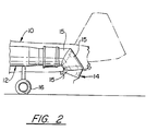
- the engine generally indicated by reference numeral 10 is mounted in an aircraft generally indicated by reference numeral 12 which engine includes the exhaust nozzle generally indicated by reference numeral 14 and the three bearing ducts generally indicated by reference numeral 15.
- the ducts 15 are capable of being counter-rotated and as shown in Fig. 1 are positioned for horizontal flight condition and in Fig. 2 for STOVL condition. Positioning the nozzle for obtaining the vectoring feature is by articulating the three ducts to rotate around the respective bearings to attain the desired attitude.
- the length of the exhaust nozzle is sufficiently short so that it doesn't touch the ground.
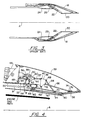
- Fig. 3 exemplifies a typical prior art exhaust nozzle that if utilized in the embodiment disclosed in Figs. 1 and 2, would not be capable of meeting the criteria noted above.
- the exhaust nozzle consists of the external flaps 18, divergent flaps 20 and convergent flaps 22.
- the prior art exhaust nozzles require balancing flaps which are depicted by reference numerals 24 and 26.
- reference numerals 24 and 26 For a more detailed description of the Prior art exhaust nozzle reference should be made to US Patent No. 3,792,815, supra and which is incorporated herein by reference.
- Figs. 4 and 5 are views partially in section and partially in elevation and perspective which show the compact axisymmetrical exhaust nozzle as being comprised of a combined actuator synchronizing ring and pressure balancing piston (PBSR) 30, fulcrum links 32, convergent flaps 34, divergent flaps 36 and the attendant connecting links as will be more fully described hereinbelow.
- An external flap 39 for providing an aerodynamically clean surface is also provided.
- the fulcrum link 32 which is generally triangularly shaped is operatively connected to the hydraulic actuator 46 by the link 38 which is pivotally connected to pivot 40 and the connecting link 42 which is pivotally connected to pivot 44. In this embodiment three actuators are equally spaced about the axis A.
- the PBSR 30 consist of a toroidally shaped housing 48 that is coaxially mounted relative to the engine's center axis A and is completely enclosed by virtue of the static annular structure 50 for defining chamber 52.
- Chamber 52 is divided into sub-chambers 54 and 56 by the radially extending annular member 58.
- the housing 48 moves axially relative to the static structure 50 and the chamber 56 serves as a working chamber such that the fluid admitted therein acts against the inner surface 60 of housing 48 much like the action of a typical piston.
- This pressure serves to urge the housing 48 toward the right as the pressure builds up in chamber 56 urging the connecting member 42 and link 38 to rotate the fulcrum link 32 about its pivot connection 62 to balance the load of the flaps.
- Links 64 and 66 are respectively connected to the convergent flaps 34 via the pivotal connections 68 and 70 and the divergent flaps 36 via the pivotal connection 72 and the sliding connection 74 sliding in track 76 which in turn is integrally formed on the back surface of the flap 36.
- the flaps 34 and 36 are hingedly connected to each other by the hinge connection 80 and the convergent flap is connected to the static structure 50 via the pivotal connection 82 and the fixed support arm 84.
- the PBSR 30 reacts the loads that are transmitted through the linkage and fulcrum link from the convergent flaps and the divergent flaps to balance the load produced thereby.
- this serves a similar purpose as the balancing flaps disclosed in the 3, 792,815 supra, so that these components are eliminated and a significant reduction in the C/D nozzle length is realized.
- a cooling liner 87 may be attached to the flap 34 for assuring the structural integrity of the parts.
- the cooling liner 87 is radially spaced from the flap 34 to define an axial passage for flowing fan air therein to cool the convergent flap.
- the conventional seal flaps 92 are utilized to prevent the engine working medium from escaping from the gas path between adjacent flaps.
- the actuators 46 are actuated by fuel (not shown) in a well known manner which causes the actuator connecting rod 86 to move toward the right.
- fuel not shown
- the pressure from the fan discharge air depicted by arrows B which is admitted through a plurality of holes 90 spaced around the circumference (one being shown) causes the PBSR 30 to add to the force produced by actuator 46.
- This force is transmitted to the fulcrum link 32 via the linkages as described above.
- the fulcrum link 32 positions the flaps to the desired C/D configuration.
- Fig. 6 exemplifies another embodiment of this invention where the actuator 46 (like parts depicted in all the Figs. bear the same reference numerals) is mounted within the synchronous ring (PBSR) 30.
- the PBSR is configured differently and comprises a housing 102 which is generally U-shaped in cross section and carries a pair of diametrically spaced pockets 104 supporting rollers 105 that each roll on the surface of annular static structures 107 and 109. These surfaces are sealing surfaces and require suitable sealing members.
- the working chamber 108 similar to the working chamber 56 in Fig. 4, receives pressurized fan discharge air depicted by arrows B.
- the invention provides an improved C/D exhaust nozzle, and also provides a C/D exhaust nozzle for gas turbine engines that is characterized as being shorter than heretofore known C/D exhaust nozzles and is capable of use in STOVL aircraft.
- At least the preferred embodiments have the following advantages over prior art nozzles:
Landscapes
- Engineering & Computer Science (AREA)
- Chemical & Material Sciences (AREA)
- Combustion & Propulsion (AREA)
- Mechanical Engineering (AREA)
- General Engineering & Computer Science (AREA)
- Supercharger (AREA)
- Control Of Turbines (AREA)
Abstract
Description
Claims (8)
- A C/D exhaust nozzle (14) for gas turbine engine power plants (10) powering aircraft, comprising convergent flaps (34) and divergent flaps (36), a synchronization ring means (30) for positioning said convergent flaps (34) and said divergent flaps (36), and means for actuating said exhaust nozzle to change its C/D configuration, said means includes an actuator (46) connected to said synchronization ring means (30), said synchronization ring means defining piston means for balancing the loads created by said convergent flaps and said divergent flaps.
- A C/D exhaust nozzle as claimed in claim 1, wherein said turbine power plant includes means for flowing fan discharge air, said piston means being powered by said fan discharge air.
- A C/D exhaust nozzle as claimed in claim 1 or 2, additionally comprising a fulcrum link (32), and linkage means (38,64,66) interconnecting said actuator (46), said synchronization ring means (30), said convergent flaps (34) and said divergent flaps (36) to said fulcrum link (32).
- An axisymmetrical C/D exhaust nozzle (14) for gas turbine engine power plants (10) having a central axis powering STOVL aircraft, comprising convergent flaps (34) and divergent flaps (36), a synchronization ring means (30) coaxially disposed relative to said axis for positioning said convergent flaps (34) and said divergent flaps (36), and means for actuating said exhaust nozzle to change its C/D configuration, said means including a hydraulic actuator (46) with engine fuel being the hydraulic medium connected to said synchronization ring means (30), said synchronization ring means defining piston means for balancing the loads created by said convergent flaps (34) and said divergent flaps (36).
- An axisymmetrical C/D exhaust nozzle as claimed in claim 4, further comprising a static annular structure (50;109) coaxially disposed relative to said axis, said synchronization ring means (30) including an annular shaped housing (52;102) including a forward enclosing end concentrically mounted relative to said static structure for defining a working chamber, and means for leading engine air to said working chamber through an aperture (90;110) formed in said static structure.
- An axisymmetrical C/D exhaust nozzle as claimed in claim 5, additionally comprising a triangular shaped fulcrum link (32) and means for pivotally mounting said fulcrum link (32) to said static structure (50;l09).
- An axisymmetrical C/D exhaust nozzle as claimed in claim 6, having link means (64,66) for attaching said divergent flap (36) to said fulcrum link (32) and said convergent flap (34) to said fulcrum link (32).
- An axisymmetrical C/D exhaust nozzle as claimed in claim 7, wherein one triangular end of said fulcrum link (32) is attached to said link means (64) attaching said convergent flap (34) and another triangular end of said fulcrum link (32) is attached to said link means (66) attaching said divergent flap (36).
Applications Claiming Priority (2)
| Application Number | Priority Date | Filing Date | Title |
|---|---|---|---|
| US08/721,890 US5813611A (en) | 1996-09-27 | 1996-09-27 | Compact pressure balanced fulcrum-link nozzle |
| US721890 | 1996-09-27 |
Publications (3)
| Publication Number | Publication Date |
|---|---|
| EP0833046A2 true EP0833046A2 (en) | 1998-04-01 |
| EP0833046A3 EP0833046A3 (en) | 1999-10-20 |
| EP0833046B1 EP0833046B1 (en) | 2003-04-02 |
Family
ID=24899736
Family Applications (1)
| Application Number | Title | Priority Date | Filing Date |
|---|---|---|---|
| EP97307620A Expired - Lifetime EP0833046B1 (en) | 1996-09-27 | 1997-09-29 | Compact pressure balanced nozzle |
Country Status (5)
| Country | Link |
|---|---|
| US (1) | US5813611A (en) |
| EP (1) | EP0833046B1 (en) |
| JP (1) | JPH10103153A (en) |
| KR (1) | KR100453669B1 (en) |
| DE (1) | DE69720358T2 (en) |
Cited By (5)
| Publication number | Priority date | Publication date | Assignee | Title |
|---|---|---|---|---|
| WO2003033899A1 (en) * | 2001-10-17 | 2003-04-24 | Gateway Space Transport, Inc. | Apparatus and method for thrust vector control |
| CN104033275A (en) * | 2014-06-09 | 2014-09-10 | 中国航空工业集团公司沈阳发动机设计研究所 | Mechanism for controlling contraction section of two-dimensional nozzle |
| CN104033276A (en) * | 2014-06-09 | 2014-09-10 | 中国航空工业集团公司沈阳发动机设计研究所 | Mechanism for controlling throat area of two-dimensional nozzle |
| CN111828196A (en) * | 2020-07-04 | 2020-10-27 | 张帅 | Aircraft engine tail nozzle |
| CN113864078A (en) * | 2021-12-03 | 2021-12-31 | 中国航发沈阳发动机研究所 | High stealthy binary thrust vectoring nozzle |
Families Citing this family (18)
| Publication number | Priority date | Publication date | Assignee | Title |
|---|---|---|---|---|
| FR2857414B1 (en) * | 2003-07-08 | 2007-06-08 | Snecma Moteurs | FLEXIBLE TUBE PIPE WITH A VARIABLE SECTION OF TURBOMACHINE |
| US7032835B2 (en) * | 2004-01-28 | 2006-04-25 | United Technologies Corporation | Convergent/divergent nozzle with modulated cooling |
| US7624567B2 (en) | 2005-09-20 | 2009-12-01 | United Technologies Corporation | Convergent divergent nozzle with interlocking divergent flaps |
| US7854124B2 (en) * | 2006-10-27 | 2010-12-21 | United Technologies Corporation | Combined control for supplying cooling air and support air in a turbine engine nozzle |
| US8205454B2 (en) * | 2007-02-06 | 2012-06-26 | United Technologies Corporation | Convergent divergent nozzle with edge cooled divergent seals |
| US7757477B2 (en) * | 2007-02-20 | 2010-07-20 | United Technologies Corporation | Convergent divergent nozzle with slot cooled nozzle liner |
| US9719370B2 (en) * | 2007-03-30 | 2017-08-01 | United Technologies Corporation | Linkage system with wear reduction |
| US8020386B2 (en) * | 2007-08-21 | 2011-09-20 | United Technologies Corporation | Rollertrack pivoting axi-nozzle |
| US7874160B2 (en) * | 2007-08-21 | 2011-01-25 | United Technologies Corporation | Nozzle-area ratio float bias |
| FR2983917B1 (en) * | 2011-12-07 | 2013-12-27 | Snecma | CONVERGENT-DIVERGENT TUYERE OF TURBOMACHINE |
| US9689346B2 (en) | 2013-04-12 | 2017-06-27 | United Technologies Corporation | Gas turbine engine convergent/divergent exhaust nozzle divergent seal with dovetail interface |
| FR3026774B1 (en) * | 2014-10-07 | 2020-07-17 | Safran Aircraft Engines | TURBOMACHINE COMPRISING A BLOWER ROTOR BRAKING DEVICE. |
| US9856956B2 (en) * | 2015-01-20 | 2018-01-02 | United Technologies Corporation | Rod-and-bracket connector system for securing a pivoting member to a guide anchor moveably secured within a guide track |
| US9951717B2 (en) | 2015-04-15 | 2018-04-24 | Hamilton Sundstrand Corporation | Asymmetric load compensation system |
| FR3062425B1 (en) * | 2017-01-30 | 2021-01-08 | Safran Aircraft Engines | TURBOMACHINE FUEL SUPPLY CIRCUIT |
| FR3062422B1 (en) * | 2017-01-30 | 2021-05-21 | Safran Aircraft Engines | TURBOMACHINE FUEL SUPPLY SYSTEM |
| CN112431694B (en) * | 2020-11-20 | 2021-11-05 | 哈尔滨工程大学 | Expandable spray pipe using flexible material and external truss structure |
| CN114109645B (en) * | 2021-11-12 | 2023-12-19 | 中国航发沈阳发动机研究所 | Axisymmetric expansion spray pipe movement mechanism |
Citations (7)
| Publication number | Priority date | Publication date | Assignee | Title |
|---|---|---|---|---|
| US3792815A (en) | 1972-11-24 | 1974-02-19 | United Aircraft Corp | Balanced flap converging/diverging nozzle |
| US3899133A (en) | 1973-09-21 | 1975-08-12 | Moteurs D Aviat De France Soc | Nozzles having a variable cross-section |
| US4440347A (en) | 1981-12-28 | 1984-04-03 | United Technologies Corporation | Simplified means for balancing the loads on a variable area nozzle |
| US4440346A (en) | 1981-12-28 | 1984-04-03 | United Technologies Corporation | Axially translatable variable area convergent/divergent nozzle |
| US4456178A (en) | 1982-12-27 | 1984-06-26 | United Technologies Corporation | Exhaust nozzle assembly with dual unison ring structure |
| US5011080A (en) | 1990-04-18 | 1991-04-30 | United Technologies Corporation | Convergent/divergent nozzle construction |
| US5215256A (en) | 1992-07-16 | 1993-06-01 | Barcza W Kevin | Flap hinge arrangement for a convergent/divergent nozzle |
Family Cites Families (8)
| Publication number | Priority date | Publication date | Assignee | Title |
|---|---|---|---|---|
| GB858579A (en) * | 1957-01-17 | 1961-01-11 | Havilland Engine Co Ltd | Adjustable propulsion nozzles |
| FR2227433B1 (en) * | 1973-04-27 | 1975-08-22 | Snecma | |
| GB1444391A (en) * | 1973-05-02 | 1976-07-28 | Rolls Royce | Exhaust nozzle structures |
| US4000854A (en) * | 1975-10-02 | 1977-01-04 | General Electric Company | Thrust vectorable exhaust nozzle |
| US4049198A (en) * | 1976-06-17 | 1977-09-20 | The United States Of America As Represented By The Secretary Of The Air Force | Duct pressure actuated nozzle |
| GB2254377B (en) * | 1981-02-28 | 1993-03-31 | Rolls Royce | Pressure balanced variable area nozzle |
| US4447009A (en) * | 1981-12-28 | 1984-05-08 | United Technologies Corporation | Three-dimensional axially translatable convergent/divergent nozzle assembly |
| US4420932A (en) * | 1982-03-02 | 1983-12-20 | The United States Of America As Represented By The Secretary Of The Air Force | Pressure control system for convergent-divergent exhaust nozzle |
-
1996
- 1996-09-27 US US08/721,890 patent/US5813611A/en not_active Expired - Lifetime
-
1997
- 1997-09-25 JP JP9276680A patent/JPH10103153A/en not_active Ceased
- 1997-09-26 KR KR1019970049134A patent/KR100453669B1/en not_active IP Right Cessation
- 1997-09-29 EP EP97307620A patent/EP0833046B1/en not_active Expired - Lifetime
- 1997-09-29 DE DE69720358T patent/DE69720358T2/en not_active Expired - Fee Related
Patent Citations (7)
| Publication number | Priority date | Publication date | Assignee | Title |
|---|---|---|---|---|
| US3792815A (en) | 1972-11-24 | 1974-02-19 | United Aircraft Corp | Balanced flap converging/diverging nozzle |
| US3899133A (en) | 1973-09-21 | 1975-08-12 | Moteurs D Aviat De France Soc | Nozzles having a variable cross-section |
| US4440347A (en) | 1981-12-28 | 1984-04-03 | United Technologies Corporation | Simplified means for balancing the loads on a variable area nozzle |
| US4440346A (en) | 1981-12-28 | 1984-04-03 | United Technologies Corporation | Axially translatable variable area convergent/divergent nozzle |
| US4456178A (en) | 1982-12-27 | 1984-06-26 | United Technologies Corporation | Exhaust nozzle assembly with dual unison ring structure |
| US5011080A (en) | 1990-04-18 | 1991-04-30 | United Technologies Corporation | Convergent/divergent nozzle construction |
| US5215256A (en) | 1992-07-16 | 1993-06-01 | Barcza W Kevin | Flap hinge arrangement for a convergent/divergent nozzle |
Cited By (9)
| Publication number | Priority date | Publication date | Assignee | Title |
|---|---|---|---|---|
| WO2003033899A1 (en) * | 2001-10-17 | 2003-04-24 | Gateway Space Transport, Inc. | Apparatus and method for thrust vector control |
| US6622472B2 (en) | 2001-10-17 | 2003-09-23 | Gateway Space Transport, Inc. | Apparatus and method for thrust vector control |
| CN104033275A (en) * | 2014-06-09 | 2014-09-10 | 中国航空工业集团公司沈阳发动机设计研究所 | Mechanism for controlling contraction section of two-dimensional nozzle |
| CN104033276A (en) * | 2014-06-09 | 2014-09-10 | 中国航空工业集团公司沈阳发动机设计研究所 | Mechanism for controlling throat area of two-dimensional nozzle |
| CN104033275B (en) * | 2014-06-09 | 2016-02-17 | 中国航空工业集团公司沈阳发动机设计研究所 | A kind of two-dimensional nozzle converging portion control mechanism |
| CN104033276B (en) * | 2014-06-09 | 2016-05-04 | 中国航空工业集团公司沈阳发动机设计研究所 | A kind of throat area controlling organization of two-dimensional nozzle |
| CN111828196A (en) * | 2020-07-04 | 2020-10-27 | 张帅 | Aircraft engine tail nozzle |
| CN113864078A (en) * | 2021-12-03 | 2021-12-31 | 中国航发沈阳发动机研究所 | High stealthy binary thrust vectoring nozzle |
| CN113864078B (en) * | 2021-12-03 | 2022-02-22 | 中国航发沈阳发动机研究所 | High stealthy binary thrust vectoring nozzle |
Also Published As
| Publication number | Publication date |
|---|---|
| KR19980025050A (en) | 1998-07-06 |
| DE69720358T2 (en) | 2003-10-30 |
| EP0833046B1 (en) | 2003-04-02 |
| EP0833046A3 (en) | 1999-10-20 |
| US5813611A (en) | 1998-09-29 |
| KR100453669B1 (en) | 2004-12-17 |
| JPH10103153A (en) | 1998-04-21 |
| DE69720358D1 (en) | 2003-05-08 |
Similar Documents
| Publication | Publication Date | Title |
|---|---|---|
| EP0833046B1 (en) | Compact pressure balanced nozzle | |
| US5797544A (en) | C/D nozzle with synchronizing ring link suspension | |
| US5794850A (en) | Enclosed pressure balanced sync ring nozzle | |
| US6543718B2 (en) | Engine arrangement | |
| EP1873386B1 (en) | Fan variable area nozzle for a gas turbine engine fan nacelle | |
| US5261605A (en) | Axisymmetric nozzle with gimbled unison ring | |
| EP0503963B1 (en) | Thrust load path for vectoring nozzle | |
| US4755104A (en) | Stator vane linkage | |
| EP2134949B1 (en) | Fan variable area nozzle for a gas turbine engine fan nacelle with drive ring actuation system | |
| US6415599B1 (en) | Engine interface for axisymmetric vectoring nozzle | |
| US3954225A (en) | Apparatus for controlling exhaust nozzle flaps | |
| EP3336340B1 (en) | An actuation mechanism for a convergent/divergent gas turbine nozzle | |
| JPH0261617B2 (en) | ||
| GB2404222A (en) | Turbine engine nozzle | |
| US6199772B1 (en) | Linear actuation and vectoring ring support mechanism for axisymmetric vectoring nozzle | |
| WO1992003649A1 (en) | Axisymmetric nozzle with gimbled unison ring | |
| US6212877B1 (en) | Vectoring ring support and actuation mechanism for axisymmetric vectoring nozzle with a universal joint | |
| EP3358149B1 (en) | Bleed valve with neutral or closing bias | |
| JPH0257223B2 (en) | ||
| EP1995442B1 (en) | Turbine engine valve assembly | |
| GB2429242A (en) | Turbine engine nozzle | |
| EP0091786A1 (en) | Variable geometry nozzles for turbomachines |
Legal Events
| Date | Code | Title | Description |
|---|---|---|---|
| PUAI | Public reference made under article 153(3) epc to a published international application that has entered the european phase |
Free format text: ORIGINAL CODE: 0009012 |
|
| AK | Designated contracting states |
Kind code of ref document: A2 Designated state(s): DE FR GB |
|
| AX | Request for extension of the european patent |
Free format text: AL;LT;LV;RO;SI |
|
| PUAL | Search report despatched |
Free format text: ORIGINAL CODE: 0009013 |
|
| AK | Designated contracting states |
Kind code of ref document: A3 Designated state(s): AT BE CH DE DK ES FI FR GB GR IE IT LI LU MC NL PT SE |
|
| AX | Request for extension of the european patent |
Free format text: AL;LT;LV;RO;SI |
|
| RIC1 | Information provided on ipc code assigned before grant |
Free format text: 6F 02K 1/00 A, 6F 02K 1/12 B, 6F 02K 1/15 B |
|
| 17P | Request for examination filed |
Effective date: 20000417 |
|
| AKX | Designation fees paid |
Free format text: DE FR GB |
|
| 17Q | First examination report despatched |
Effective date: 20020204 |
|
| GRAH | Despatch of communication of intention to grant a patent |
Free format text: ORIGINAL CODE: EPIDOS IGRA |
|
| GRAH | Despatch of communication of intention to grant a patent |
Free format text: ORIGINAL CODE: EPIDOS IGRA |
|
| GRAA | (expected) grant |
Free format text: ORIGINAL CODE: 0009210 |
|
| AK | Designated contracting states |
Designated state(s): DE FR GB |
|
| REG | Reference to a national code |
Ref country code: GB Ref legal event code: FG4D |
|
| REF | Corresponds to: |
Ref document number: 69720358 Country of ref document: DE Date of ref document: 20030508 Kind code of ref document: P |
|
| ET | Fr: translation filed | ||
| PLBE | No opposition filed within time limit |
Free format text: ORIGINAL CODE: 0009261 |
|
| STAA | Information on the status of an ep patent application or granted ep patent |
Free format text: STATUS: NO OPPOSITION FILED WITHIN TIME LIMIT |
|
| 26N | No opposition filed |
Effective date: 20040105 |
|
| PGFP | Annual fee paid to national office [announced via postgrant information from national office to epo] |
Ref country code: FR Payment date: 20080904 Year of fee payment: 12 |
|
| PGFP | Annual fee paid to national office [announced via postgrant information from national office to epo] |
Ref country code: DE Payment date: 20080930 Year of fee payment: 12 |
|
| REG | Reference to a national code |
Ref country code: FR Ref legal event code: ST Effective date: 20100531 |
|
| PG25 | Lapsed in a contracting state [announced via postgrant information from national office to epo] |
Ref country code: FR Free format text: LAPSE BECAUSE OF NON-PAYMENT OF DUE FEES Effective date: 20090930 Ref country code: DE Free format text: LAPSE BECAUSE OF NON-PAYMENT OF DUE FEES Effective date: 20100401 |
|
| PGFP | Annual fee paid to national office [announced via postgrant information from national office to epo] |
Ref country code: GB Payment date: 20120926 Year of fee payment: 16 |
|
| GBPC | Gb: european patent ceased through non-payment of renewal fee |
Effective date: 20130929 |
|
| PG25 | Lapsed in a contracting state [announced via postgrant information from national office to epo] |
Ref country code: GB Free format text: LAPSE BECAUSE OF NON-PAYMENT OF DUE FEES Effective date: 20130929 |