EP0833041B1 - An electromagnetic actuator for activating an engine latchable rocker arm - Google Patents
An electromagnetic actuator for activating an engine latchable rocker arm Download PDFInfo
- Publication number
- EP0833041B1 EP0833041B1 EP97307109A EP97307109A EP0833041B1 EP 0833041 B1 EP0833041 B1 EP 0833041B1 EP 97307109 A EP97307109 A EP 97307109A EP 97307109 A EP97307109 A EP 97307109A EP 0833041 B1 EP0833041 B1 EP 0833041B1
- Authority
- EP
- European Patent Office
- Prior art keywords
- link
- connecting link
- actuator
- armature
- linkage
- Prior art date
- Legal status (The legal status is an assumption and is not a legal conclusion. Google has not performed a legal analysis and makes no representation as to the accuracy of the status listed.)
- Expired - Lifetime
Links
Images

Classifications
-
- F—MECHANICAL ENGINEERING; LIGHTING; HEATING; WEAPONS; BLASTING
- F02—COMBUSTION ENGINES; HOT-GAS OR COMBUSTION-PRODUCT ENGINE PLANTS
- F02D—CONTROLLING COMBUSTION ENGINES
- F02D13/00—Controlling the engine output power by varying inlet or exhaust valve operating characteristics, e.g. timing
- F02D13/02—Controlling the engine output power by varying inlet or exhaust valve operating characteristics, e.g. timing during engine operation
- F02D13/06—Cutting-out cylinders
-
- F—MECHANICAL ENGINEERING; LIGHTING; HEATING; WEAPONS; BLASTING
- F01—MACHINES OR ENGINES IN GENERAL; ENGINE PLANTS IN GENERAL; STEAM ENGINES
- F01L—CYCLICALLY OPERATING VALVES FOR MACHINES OR ENGINES
- F01L1/00—Valve-gear or valve arrangements, e.g. lift-valve gear
- F01L1/12—Transmitting gear between valve drive and valve
- F01L1/18—Rocking arms or levers
- F01L1/185—Overhead end-pivot rocking arms
-
- F—MECHANICAL ENGINEERING; LIGHTING; HEATING; WEAPONS; BLASTING
- F01—MACHINES OR ENGINES IN GENERAL; ENGINE PLANTS IN GENERAL; STEAM ENGINES
- F01L—CYCLICALLY OPERATING VALVES FOR MACHINES OR ENGINES
- F01L13/00—Modifications of valve-gear to facilitate reversing, braking, starting, changing compression ratio, or other specific operations
- F01L13/0005—Deactivating valves
-
- F—MECHANICAL ENGINEERING; LIGHTING; HEATING; WEAPONS; BLASTING
- F01—MACHINES OR ENGINES IN GENERAL; ENGINE PLANTS IN GENERAL; STEAM ENGINES
- F01L—CYCLICALLY OPERATING VALVES FOR MACHINES OR ENGINES
- F01L1/00—Valve-gear or valve arrangements, e.g. lift-valve gear
- F01L1/12—Transmitting gear between valve drive and valve
- F01L1/18—Rocking arms or levers
- F01L2001/186—Split rocking arms, e.g. rocker arms having two articulated parts and means for varying the relative position of these parts or for selectively connecting the parts to move in unison
-
- F—MECHANICAL ENGINEERING; LIGHTING; HEATING; WEAPONS; BLASTING
- F01—MACHINES OR ENGINES IN GENERAL; ENGINE PLANTS IN GENERAL; STEAM ENGINES
- F01L—CYCLICALLY OPERATING VALVES FOR MACHINES OR ENGINES
- F01L2820/00—Details on specific features characterising valve gear arrangements
- F01L2820/03—Auxiliary actuators
- F01L2820/031—Electromagnets
-
- Y—GENERAL TAGGING OF NEW TECHNOLOGICAL DEVELOPMENTS; GENERAL TAGGING OF CROSS-SECTIONAL TECHNOLOGIES SPANNING OVER SEVERAL SECTIONS OF THE IPC; TECHNICAL SUBJECTS COVERED BY FORMER USPC CROSS-REFERENCE ART COLLECTIONS [XRACs] AND DIGESTS
- Y02—TECHNOLOGIES OR APPLICATIONS FOR MITIGATION OR ADAPTATION AGAINST CLIMATE CHANGE
- Y02T—CLIMATE CHANGE MITIGATION TECHNOLOGIES RELATED TO TRANSPORTATION
- Y02T10/00—Road transport of goods or passengers
- Y02T10/10—Internal combustion engine [ICE] based vehicles
- Y02T10/12—Improving ICE efficiencies
Definitions
- the present invention relates to an engine valve control actuator and more specifically, to a latchable engine valve control system where a knee action linkage is connected to a solenoid.
- Variable valve control systems for multiple valve engines wherein the intake and/or exhaust valves can either be selectively actuated or actuated with various lift profiles are well known in the art.
- Example systems are shown in U.S. Patent Nos. 4,151,817 and 4,203,397.
- Patent 4,151,817 discloses a primary rocker arm element engageable with a first cam profile, a secondary rocker arm element engageable with a second cam profile, and means to interconnect or latch the primary and secondary rocker arm elements.
- Patent 4,203,397 discloses an apparatus to selectively engage or disengage an engine poppet valve so as to connect or disconnect the engine valve from the balance of the valve gear using a latch mechanism thereby causing the valve to operate or remain stationary.
- latchable rocker arm mechanisms known in the prior art require a relatively high activation force to shift the mechanism from an operable to an inoperable state.
- Typical solenoid actuators when used with prior art mechanisms, provide a high force level so that synchronization with the valve gear is not required and thus require a large package size and/or a high level of electrical current for actuation. If a cam position synchronization capability is available, then a relatively low force producing solenoid can be used since the latchable rocker arm is only deactivated when the valve is closed and the internal loads on the latch mechanism are at a minimum.
- This synchronization can be provided by a sensor and electronic control unit or mechanically by a preload spring. If electronic synchronization capability is not available, then a special spring loaded linkage can be adapted to the rocker arm to allow the solenoid to fully engage and preload the rocker arm for automatic activation when the valve gear unloads when the engine valve closes.
- bellcrank linkage is disclosed in U.S. patent application US-A-5 619 958 which operates to mechanically increase and translate the motion of a solenoid to the latchable rocker arm but does not provide a high lock-in force at maximum travel which would conserve energy.
- US-A-5,524,580 describes a solenoid operated latchable rocker arm mechanism
- the solenoid is pivotally connected to an operating arm close to its pivot point.
- the moving core of the solenoid is connected to the operating arm.
- a second remote end of the operating arm engages with a sliding actuation plate which operates the latching and unlatching mechanism in the rocker arm.
- a sliding actuation plate which operates the latching and unlatching mechanism in the rocker arm.
- a knee type linkage is used in an actuator to transfer the motion of an electrical solenoid to a latchable rocker arm.
- the knee linkage provides an increasing mechanical advantage and a very high lock-in force at the point of maximum travel to accommodate the forces generated by the latch mechanism of the latchable rocker arm.
- the present invention thus results in a reduced force level output requirement for the solenoid thereby reducing the size of the solenoid for improved packaging parameters and energy consumption as compared to prior art devices.
- the knee linkage of the present invention has first and second connecting links and a primary link with an electrical solenoid acting on the primary link.
- the first connecting link is attached to an output link which is pivoted on the solenoid frame.
- the output link contacts and actuates the latchable rocker arm.
- the second connecting link is attached to a return spring where the return spring reacts against the solenoid frame to return the knee linkage to its nonactivated position upon deenergization of the solenoid.
- the knee linkage When the solenoid is deactivated, the knee linkage is bent at a center pivot, where the center pivot rotatably connects the primary link, the first connecting link and the second connecting link.
- the center pivot When the solenoid is activated, the center pivot is forced into a position where the first pivot, the second pivot and the center pivot lie approximately along a common axis thereby providing an extremely high lock-in force and a mechanical advantage for a reduction in the required force that the solenoid must produce for actuation.
- FIG. 1 of the drawings a cross-sectional view of the actuator linkage 2 of the present invention is shown in a deactivated state.
- the actuator linkage 2 is largely contained within a linkage housing 4.
- An actuator plate 6 is electromagnetically forced downward upon activation of a solenoid coil 32 (see FIG. 3) and serves to supply a downward force to a primary link 8 which in turn causes first connecting link 10A and second connecting link 12A to move and operate against output link 14.
- the primary link 8 is rotatably supported on pin 16 which extends from the actuator plate 6 at a first end of primary link 8 and is rotatably supported on pin 18 at a second end of primary link 8.
- the first connecting link 10A is supported at a first end by pin 18 and at a second end by pin 20 where pin 20 is connected to output link 14.
- the second connecting link 12A is rotatably connected to pin 18 at a first end and rotatably connected to pin 22 at a second end where pin 22 is driven against the linkage return spring 26 through the end cap 28 where the linkage return spring 26 is supported at a first end at the return end cap 28 and at a second end at the linkage housing 4.
- the output link 14 is rotatably supported on pin 24 and is actuated through movement of the first connecting link 10A through the pin 20. Now referring to FIG.
- the actuator linkage 2 of the present invention is shown in an actuated state where the actuator plate 6 has been moved downward by electromagnetic attraction to solenoid coil 32 (see FIG. 3) to move the primary link 8 downward causing the first connecting link 10A to tend to become coaxially aligned with the second connecting link 12A thereby causing the output link 14 to move laterally in a leftward direction. If the output link 14 is forced to move in a rightward direction, then the linkage return spring 26 would become compressed by the end cap 28 the condition of which is not illustrated in FIG. 2. Generally, the force generated by the linkage return spring 26 must exceed the maximum force needed to activate the device to be actuated such as latchable rocker arm 62 (see FIG. 7).
- first connecting link 10A and the second connecting link 12A results in an increase in the mechanical advantage as the primary link 8 is moved downward by the actuator plate 6 eventually reaching the configuration shown in FIG. 2 where the first, connecting link 10A and the second connecting link 12A are in appropriate axial alignment to accommodate manufacturing tolerances, the first connecting link 10A and the second connecting link 12A could actually move past the axial alignment position and could be limited by a mechanical stop (not shown).
- FIG. 3 is the top view of the actuator 30 of the present invention which includes the coil 32 which is connected to a source of electrical excitation through connector 34.
- An armature 36 causes the actuator plates 6 to be pulled downwardly against the coil 32 thereby causing the pins 16 and 16' to move which are connected to the primary links 8 and 8' to move downward thereby causing the actuator linkage 2 to become activated as shown in FIG. 2.
- the coil 32 is contained within the upper solenoid housing 38 which can be a stamped metal piece which is in turn mechanically connected to a lower solenoid housing 39 where the lower solenoid housing 39 extends to form both the linkage housing 4 on the right side of the actuator 30 and the linkage housing 4' on the lefthand side of the actuator 30.
- the actuator linkage 2 is shown on the right side of the actuator 30 and a mirror image of actuator linkage 2 is mounted to the left side of the lower solenoid housing 39 and will be hereinafter referred to as the left actuator linkage 2'.
- the primary link 8 is duplicated and installed on the left actuator linkage 2' and labeled as primary link 8' and the leftward extending pin 16' is substantially identical to the pin 16 described with respect to actuator linkage 2.
- the right linkage return spring 26 and the left linkage return spring 26' are shown in FIG. 3 . In this manner, the right actuator linkage 2 can serve to actuate a first latchable rocker arm while the left actuator linkage 2' can actuate a second latchable rocker arm both using the same solenoid coil 32.
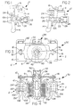
- FIG. 4 of the drawings a cross-sectional view of the actuator 30 of the present invention is shown.
- the mechanics of the right actuator linkage 2 is duplicated in the left actuator linkage 2' along with the components that make up the right and left actuator linkages 2 and 2' including right and left primary links 8 and 8'; right outer and inner first connecting links 10A and 10B; right outer and inner second connecting links 12A and 12B; right and left pins 22 and 22'; right and left pins 24 and 24'; left outer and inner first connecting links 10A' and 10B'; and left outer and inner second connecting links 12A' and 12B'.
- An actuation spring 42 operates between the actuator plate 6 and armature 36 where the armature 36 passes through the center of the actuator plate 6 with mechanical support in only one direction through the pivot washer 48 which sits on top of the armature 36.
- the armature 36 moves downward to contact the stator 40 acting against actuation spring 42 which reacts against the retainer 50 which is attached to the armature 36. If the actuator plate 6 cannot move downward due to the internal forces on the latchable rocker arm 62 (see FIG. 7), the actuation spring 42 is compressed so as to preload the actuator plate 6.
- a return spring 44 operates between the actuator plate 6 and the upper solenoid housing 38 thereby forcing the actuator plate 6 away from the upper solenoid housing 38 when the coil 32 is deenergized.
- the actuator plates 6 sits on the pivot washer 48 where the pivot washer 48 contacts and is supported by the armature 36.
- the pivot washer 48 is radiused such that the actuator plate 6 can rock with respect to the armature 36 thereby allowing both the right and left actuator linkages 2 and 2' to be actuated independently or together.
- the armature 36 is electromagnetically attracted to the stator 40 when the coil 32 is electrically energized through electrical connector 34.
- the coil 32 is contained and supported within the lower solenoid housing 39 and the upper solenoid housing 38.
- the armature 36 moves downward toward and contacts the stator 40 thereby tending to compress the actuator spring 42 providing a downward force against the actuator plate 6. If the actuator plate 6 is unable to move, then the actuator spring 42 comes compressed and provides a preload on the actuator plate 6 moving the actuator plate 6 when the right actuator linkage 2 or the left actuator linkage 2' becomes free to move.
- the armature 36 moves away from the stator 40 by action of the return spring 44.
- the right actuator linkage 2 consists of a right primary link 8 which is attached to the actuator plate 6 at the pin 16 at a first end of the right primary link 8.
- a second end of primary link 8 is rotatably connected to the right outer first connecting link 10A and the right inner first connecting link 10B by pin 18.
- the second end of primary link 8 is also rotatably connected to the right outer second connecting link 12A and the inner second connecting link 12B by pin 18.
- the right primary link 8 is coupled to two pairs of links: the right inner and outer first connecting links 10A,10B and the right inner and outer second connecting links 12A,12B.
- Not shown in the particular cross-section of FIG. 4 are the right output link 14 and the left output link 14' although the pins 24 and 24' on which the output links 14 and 14' rotate are shown.
- FIG. 5 of the drawings a partial perspective view of the actuator 30 of the present invention is shown with the right linkage housing 4 and left linkage housing 4' removed and the lower solenoid housing 39 removed for illustrative purposes.
- the actuation spring 42 is not shown.
- the right actuator linkage 2 more clearly illustrated is the functioning of the right primary link 8 which is supported and moved with the actuator plate 6 by the right pin 16.
- the right primary link 8 is connected at a second end to pin 18.
- Pin 18 rotatably engages both the right first connecting links 10A and 10B where the right outer and inner first connecting links 10A and 10B are connected to right output link 14 with pin 20.
- the right outer and inner second connecting links 12A and 12B are rotatably connected to the primary link 8 through pin 18 at their first ends and are engaged to the end cap 28 through pin 22 at second ends of the right outer and inner second connecting links 12A and 12B.
- the right output link 14 is rotatably supported by pin 24 such that vertical movement of the right primary link 8 translates into a rotary motion of the right output link 14 about the pin 24 when the coil 32 is energized.
- the left actuator linkage 2' operates with left primary link 8' operating to move the left output link 14' as the actuator plate 6 is moved upward and downward by electromagnetic attraction of the coil 32 and the return spring 44.
- FIG. 6 of the drawings a second perspective view of the actuator 30 of the present invention is shown.
- the actuation spring 42 has also been omitted in this figure.
- the lower solenoid housing 39 which extends to form both the right hand linkage housing 4 and the lefthand linkage housing 4' is shown and is attached to the upper solenoid housing 38.
- the pin 22 which is attached to the right outer and inner second connecting links 12A and 12B is shown moving in a slot formed in the linkage housing 4 against the linkage return spring 26 should the right output link 14 be in a nonmoveable state. Many of the elements previously described in relation to FIG. 5 are shown.
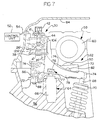
- FIG. 7 of the drawings is a cutaway view of the actuator 30 of the present invention adapted to operate a latchable rocker arm 62 as more fully shown and described in US-A- 5 623 897 filed on March 22, 1996 and assigned to the same assignee Eaton Corporation.
- the actuator 30 of the present invention along with the latchable rocker arm 62 is adapted to and shown as installed as part of the valve train on an internal combustion engine.
- a portion of the engine cylinder head 56 of an internal combustion engine of the overhead cam type is shown along with the camshaft 58, the hydraulic lash adjuster 64, the engine poppet valve 68, the valve spring 70 and the valve cover 84.
- the latchable rocker arm 62 is of the type which is particularly adapted to selectively activate or deactivate an engine poppet valve 68 and comprises a mechanism which is shiftable between an active mode wherein it is operable to open the engine poppet valve 68 in response to the motion of the cam 58, and an inactive mode wherein the engine valve 68 is not opened by action of the cam 58.
- the latchable rocker arm 62 comprises an inner rocker arm 72 which is engagable with the cam 58 at the cam lobe 60 supported on the cylinder head 56 of the engine and an outer rocker arm 74 which is engagable with the engine poppet valve 68 which is maintained normally closed by a valve spring 70.
- a biasing spring 86 operates between the inner rocker arm 72 and the outer rocker arm 74 so as to the bias the inner rocker arm 72 for engagement with the cam lobe 60 through the roller 80 and the outer rocker arm 74 into engagement with the plunger 67 which rides in the main body 66 of the lash adjuster 64.
- the construction and the function of the lash adjuster 64 are well known in the art and will not be described in detail herein.
- the biasing spring 86 applies sufficient force to the plunger 67 to keep the lash adjuster 64 operating in its normal range at all times.
- the roller 80 is rotatably supported on the inner rocker arm 72 by roller pin 82.
- the load on the spring 86 can be adjusted by load adjuster 88.
- a latch member 78 is slidably received on the outer rocker arm 74 and biased into a "latched” condition by a latch spring (not shown) that supplies a force between the latch member 78 and the outer rocker arm 74.
- the latch member 78 is effective to link the inner and outer rocker arms 72 and 74 so that they move together to define the "active mode" of the engine poppet valve latchable rocker arm 62 (as shown in FIG. 7) or to unlatch them where the inner rocker arm 72 is free to rotate relative to the outer rocker arm 74 to define the "inactive mode".
- a link pin 76 is rotatably supported on top of the plunger 67 and provides support for the inner rocker arm 72 and thus such that the inner rocker arm 72 is free to rotate relative to the plunger 67 and/or the link pin 76 whereas the outer rocker arm 74 is nonrotatably linked to the link pin 76 and is thus free to rotate relative to the plunger 67 and the inner rocker arm 72.
- the latch member 78 is moved into the inactive mode, the inner rocker arm 72 is free to rotate relative to the outer rocker arm 74 thereby providing for a disengagement of the cam lob 60 from the engine valve 68.
- the latchable rocker arm 62 is switched from an active mode into an inactive mode by translation of the latch member 78 on the outer rocker arm 74.
- the latch member 78 is shown in an intermediate position where the latch member 78 still engages the inner rocker arm 72 thereby linking rotation of the inner rocker arm 72 to the outer rocker arm 74 thus maintaining the active mode and operation of the engine valve 68 in response to the cam lobe 60.
- the actuator 30 has been partially energized where the actuator plate 6 has been pulled partially downward by electrical excitation of the coil 32 by the control unit 52 through electrical leads 54.
- the primary link 8' has moved downward thereby causing the left first connecting link 10A' and 10B' to extend in a knee action with respect to the left second connecting links 12A' and 12B' thereby axially displacing the left output link 14' against the latch member 78.
Landscapes
- Engineering & Computer Science (AREA)
- Mechanical Engineering (AREA)
- General Engineering & Computer Science (AREA)
- Chemical & Material Sciences (AREA)
- Combustion & Propulsion (AREA)
- Valve Device For Special Equipments (AREA)
Description
- The present application is related to patent publications US-A-5 623 897 entitled "Engine Valve Control System Using A Latchable Rocker Arm Activated by A Solenoid Mechanism" and US-A-5 619 958 entitled "Engine Valve Control System Using A Latchable Rocker Arm" both assigned to the same assignee, Eaton Corporation, of this application.
- The present invention relates to an engine valve control actuator and more specifically, to a latchable engine valve control system where a knee action linkage is connected to a solenoid.
- Variable valve control systems for multiple valve engines wherein the intake and/or exhaust valves can either be selectively actuated or actuated with various lift profiles are well known in the art. Example systems are shown in U.S. Patent Nos. 4,151,817 and 4,203,397. Patent 4,151,817 discloses a primary rocker arm element engageable with a first cam profile, a secondary rocker arm element engageable with a second cam profile, and means to interconnect or latch the primary and secondary rocker arm elements. Patent 4,203,397 discloses an apparatus to selectively engage or disengage an engine poppet valve so as to connect or disconnect the engine valve from the balance of the valve gear using a latch mechanism thereby causing the valve to operate or remain stationary.
- Generally, latchable rocker arm mechanisms known in the prior art require a relatively high activation force to shift the mechanism from an operable to an inoperable state. Typical solenoid actuators, when used with prior art mechanisms, provide a high force level so that synchronization with the valve gear is not required and thus require a large package size and/or a high level of electrical current for actuation. If a cam position synchronization capability is available, then a relatively low force producing solenoid can be used since the latchable rocker arm is only deactivated when the valve is closed and the internal loads on the latch mechanism are at a minimum. This synchronization can be provided by a sensor and electronic control unit or mechanically by a preload spring. If electronic synchronization capability is not available, then a special spring loaded linkage can be adapted to the rocker arm to allow the solenoid to fully engage and preload the rocker arm for automatic activation when the valve gear unloads when the engine valve closes.
- Some type of bellcrank or other type of travel amplification system is usually required due to the relatively low travel output of the solenoid. A bellcrank linkage is disclosed in U.S. patent application US-A-5 619 958 which operates to mechanically increase and translate the motion of a solenoid to the latchable rocker arm but does not provide a high lock-in force at maximum travel which would conserve energy.
- US-A-5,524,580 describes a solenoid operated latchable rocker arm mechanism The solenoid is pivotally connected to an operating arm close to its pivot point. The moving core of the solenoid is connected to the operating arm. A second remote end of the operating arm engages with a sliding actuation plate which operates the latching and unlatching mechanism in the rocker arm. In order to achieve sufficient movement of the actuation plate it is necessary to magnify the movement of the solenoid core and this is achieved by use of a long lever arm. This configuration takes up a lot of space on the engine.
- In accordance with the principles of the present invention, a knee type linkage is used in an actuator to transfer the motion of an electrical solenoid to a latchable rocker arm. The knee linkage provides an increasing mechanical advantage and a very high lock-in force at the point of maximum travel to accommodate the forces generated by the latch mechanism of the latchable rocker arm. The present invention thus results in a reduced force level output requirement for the solenoid thereby reducing the size of the solenoid for improved packaging parameters and energy consumption as compared to prior art devices.
- The knee linkage of the present invention has first and second connecting links and a primary link with an electrical solenoid acting on the primary link. The first connecting link is attached to an output link which is pivoted on the solenoid frame. The output link contacts and actuates the latchable rocker arm. The second connecting link is attached to a return spring where the return spring reacts against the solenoid frame to return the knee linkage to its nonactivated position upon deenergization of the solenoid.
- When the solenoid is deactivated, the knee linkage is bent at a center pivot, where the center pivot rotatably connects the primary link, the first connecting link and the second connecting link. When the solenoid is activated, the center pivot is forced into a position where the first pivot, the second pivot and the center pivot lie approximately along a common axis thereby providing an extremely high lock-in force and a mechanical advantage for a reduction in the required force that the solenoid must produce for actuation.
-
- FIG. 1 is a cross-sectional view of the actuator linkage of the present invention in a deactivated state;
- FIG. 2 is a cross-sectional view of the actuator linkage of the present invention in an activated state;
- FIG. 3 is a top view of the actuator of the present invention;
- FIG. 4 is a cross-sectional view of the actuator of the present invention;
- FIG. 5 is a partial perspective view of the actuator of the present invention;
- FIG. 6 is a perspective view of the actuator of a present invention; and
- FIG. 7 is a cross-sectional view of the latchable rocker arm assembly of the present invention.
-
- For the purposes of promoting an understanding of the principles of the invention, reference will now be made to the embodiment illustrated in the drawings and specific language will be used to describe the same. It will nevertheless be understood that no limitation of the scope of the invention is thereby intended, such alterations and further modifications in the illustrated device, and such further applications of the principles of the invention as illustrated therein being contemplated as would normally occur to one skilled in the art to which the invention relates.
- Certain terminology will be used in the following description for convenience in reference only and will not be limiting. The terms "rightward" and "leftward" will refer to directions in the drawings in connection with which the terminology is used. The terms "inwardly" and "outwardly" will refer to directions toward and away from, respectively, the geometric center of the actuator. The terms "upward" and "downward" will refer to directions as taken in the drawings in connection with which the terminology is used. All foregoing terms mentioned above include the normal derivatives and equivalents thereof.
- Now referring to FIG. 1 of the drawings, a cross-sectional view of the
actuator linkage 2 of the present invention is shown in a deactivated state. Theactuator linkage 2 is largely contained within alinkage housing 4. Anactuator plate 6 is electromagnetically forced downward upon activation of a solenoid coil 32 (see FIG. 3) and serves to supply a downward force to aprimary link 8 which in turn causes first connecting link 10A and second connectinglink 12A to move and operate againstoutput link 14. Theprimary link 8 is rotatably supported onpin 16 which extends from theactuator plate 6 at a first end ofprimary link 8 and is rotatably supported onpin 18 at a second end ofprimary link 8. The first connecting link 10A is supported at a first end bypin 18 and at a second end bypin 20 wherepin 20 is connected tooutput link 14. The second connectinglink 12A is rotatably connected topin 18 at a first end and rotatably connected topin 22 at a second end wherepin 22 is driven against thelinkage return spring 26 through theend cap 28 where thelinkage return spring 26 is supported at a first end at thereturn end cap 28 and at a second end at thelinkage housing 4. Theoutput link 14 is rotatably supported onpin 24 and is actuated through movement of the first connecting link 10A through thepin 20. Now referring to FIG. 2, theactuator linkage 2 of the present invention is shown in an actuated state where theactuator plate 6 has been moved downward by electromagnetic attraction to solenoid coil 32 (see FIG. 3) to move theprimary link 8 downward causing the first connecting link 10A to tend to become coaxially aligned with the second connectinglink 12A thereby causing theoutput link 14 to move laterally in a leftward direction. If theoutput link 14 is forced to move in a rightward direction, then thelinkage return spring 26 would become compressed by theend cap 28 the condition of which is not illustrated in FIG. 2. Generally, the force generated by thelinkage return spring 26 must exceed the maximum force needed to activate the device to be actuated such as latchable rocker arm 62 (see FIG. 7). The knee action of the first connecting link 10A and the second connectinglink 12A results in an increase in the mechanical advantage as theprimary link 8 is moved downward by theactuator plate 6 eventually reaching the configuration shown in FIG. 2 where the first, connecting link 10A and the second connectinglink 12A are in appropriate axial alignment to accommodate manufacturing tolerances, the first connecting link 10A and the second connectinglink 12A could actually move past the axial alignment position and could be limited by a mechanical stop (not shown). - FIG. 3 is the top view of the
actuator 30 of the present invention which includes thecoil 32 which is connected to a source of electrical excitation throughconnector 34. Anarmature 36 causes theactuator plates 6 to be pulled downwardly against thecoil 32 thereby causing thepins 16 and 16' to move which are connected to theprimary links actuator linkage 2 to become activated as shown in FIG. 2. Thecoil 32 is contained within theupper solenoid housing 38 which can be a stamped metal piece which is in turn mechanically connected to alower solenoid housing 39 where thelower solenoid housing 39 extends to form both thelinkage housing 4 on the right side of theactuator 30 and the linkage housing 4' on the lefthand side of theactuator 30. Theactuator linkage 2 is shown on the right side of theactuator 30 and a mirror image ofactuator linkage 2 is mounted to the left side of thelower solenoid housing 39 and will be hereinafter referred to as the left actuator linkage 2'. Likewise, theprimary link 8 is duplicated and installed on the left actuator linkage 2' and labeled asprimary link 8' and the leftward extending pin 16' is substantially identical to thepin 16 described with respect toactuator linkage 2. Also shown in FIG. 3 are the rightlinkage return spring 26 and the left linkage return spring 26'. In this manner, theright actuator linkage 2 can serve to actuate a first latchable rocker arm while the left actuator linkage 2' can actuate a second latchable rocker arm both using thesame solenoid coil 32. - Now referring to FIG. 4 of the drawings, a cross-sectional view of the
actuator 30 of the present invention is shown. Again, note that the mechanics of theright actuator linkage 2 is duplicated in the left actuator linkage 2' along with the components that make up the right and leftactuator linkages 2 and 2' including right and leftprimary links links pins 22 and 22'; right and leftpins 24 and 24'; left outer and inner first connecting links 10A' and 10B'; and left outer and inner second connectinglinks 12A' and 12B'. Thus, whenever reference is made to elements contained within theright actuator linkage 2 identical form, fit and function can be translated to the elements contained within the left actuator linkage 2'. - An
actuation spring 42 operates between theactuator plate 6 andarmature 36 where thearmature 36 passes through the center of theactuator plate 6 with mechanical support in only one direction through thepivot washer 48 which sits on top of thearmature 36. Thus, when thecoil 32 is energized, thearmature 36 moves downward to contact thestator 40 acting againstactuation spring 42 which reacts against theretainer 50 which is attached to thearmature 36. If theactuator plate 6 cannot move downward due to the internal forces on the latchable rocker arm 62 (see FIG. 7), theactuation spring 42 is compressed so as to preload theactuator plate 6. Areturn spring 44 operates between theactuator plate 6 and theupper solenoid housing 38 thereby forcing theactuator plate 6 away from theupper solenoid housing 38 when thecoil 32 is deenergized. Theactuator plates 6 sits on thepivot washer 48 where thepivot washer 48 contacts and is supported by thearmature 36. Thepivot washer 48 is radiused such that theactuator plate 6 can rock with respect to thearmature 36 thereby allowing both the right and leftactuator linkages 2 and 2' to be actuated independently or together. - The
armature 36 is electromagnetically attracted to thestator 40 when thecoil 32 is electrically energized throughelectrical connector 34. Thecoil 32 is contained and supported within thelower solenoid housing 39 and theupper solenoid housing 38. Thus, when thecoil 32 is electrically energized, thearmature 36 moves downward toward and contacts thestator 40 thereby tending to compress theactuator spring 42 providing a downward force against theactuator plate 6. If theactuator plate 6 is unable to move, then theactuator spring 42 comes compressed and provides a preload on theactuator plate 6 moving theactuator plate 6 when theright actuator linkage 2 or the left actuator linkage 2' becomes free to move. After the electrical current to thecoil 32 is removed, thearmature 36 moves away from thestator 40 by action of thereturn spring 44. - The
right actuator linkage 2 consists of a rightprimary link 8 which is attached to theactuator plate 6 at thepin 16 at a first end of the rightprimary link 8. A second end ofprimary link 8 is rotatably connected to the right outer first connecting link 10A and the right inner first connecting link 10B bypin 18. The second end ofprimary link 8 is also rotatably connected to the right outer second connectinglink 12A and the inner second connectinglink 12B bypin 18. Thus, the rightprimary link 8 is coupled to two pairs of links: the right inner and outer first connecting links 10A,10B and the right inner and outer second connectinglinks right output link 14 and the left output link 14' although thepins 24 and 24' on which the output links 14 and 14' rotate are shown. - Now referring to FIG. 5 of the drawings, a partial perspective view of the
actuator 30 of the present invention is shown with theright linkage housing 4 and left linkage housing 4' removed and thelower solenoid housing 39 removed for illustrative purposes. In addition, theactuation spring 42 is not shown. Referring specifically to theright actuator linkage 2 more clearly illustrated is the functioning of the rightprimary link 8 which is supported and moved with theactuator plate 6 by theright pin 16. The rightprimary link 8 is connected at a second end to pin 18.Pin 18 rotatably engages both the right first connecting links 10A and 10B where the right outer and inner first connecting links 10A and 10B are connected toright output link 14 withpin 20. Likewise, the right outer and inner second connectinglinks primary link 8 throughpin 18 at their first ends and are engaged to theend cap 28 throughpin 22 at second ends of the right outer and inner second connectinglinks right output link 14 is rotatably supported bypin 24 such that vertical movement of the rightprimary link 8 translates into a rotary motion of theright output link 14 about thepin 24 when thecoil 32 is energized. In an identical manner, the left actuator linkage 2' operates with leftprimary link 8' operating to move the left output link 14' as theactuator plate 6 is moved upward and downward by electromagnetic attraction of thecoil 32 and thereturn spring 44. - Now referring to FIG. 6 of the drawings, a second perspective view of the
actuator 30 of the present invention is shown. For clarity, theactuation spring 42 has also been omitted in this figure. Thelower solenoid housing 39 which extends to form both the righthand linkage housing 4 and the lefthand linkage housing 4' is shown and is attached to theupper solenoid housing 38. Thepin 22 which is attached to the right outer and inner second connectinglinks linkage housing 4 against thelinkage return spring 26 should theright output link 14 be in a nonmoveable state. Many of the elements previously described in relation to FIG. 5 are shown. - FIG. 7 of the drawings is a cutaway view of the
actuator 30 of the present invention adapted to operate a latchable rocker arm 62 as more fully shown and described in US-A- 5 623 897 filed on March 22, 1996 and assigned to the same assignee Eaton Corporation. Theactuator 30 of the present invention along with the latchable rocker arm 62 is adapted to and shown as installed as part of the valve train on an internal combustion engine. A portion of theengine cylinder head 56 of an internal combustion engine of the overhead cam type is shown along with thecamshaft 58, the hydraulic lash adjuster 64, theengine poppet valve 68, thevalve spring 70 and thevalve cover 84. - As illustrated herein, the latchable rocker arm 62 is of the type which is particularly adapted to selectively activate or deactivate an
engine poppet valve 68 and comprises a mechanism which is shiftable between an active mode wherein it is operable to open theengine poppet valve 68 in response to the motion of thecam 58, and an inactive mode wherein theengine valve 68 is not opened by action of thecam 58. - The latchable rocker arm 62 comprises an
inner rocker arm 72 which is engagable with thecam 58 at thecam lobe 60 supported on thecylinder head 56 of the engine and anouter rocker arm 74 which is engagable with theengine poppet valve 68 which is maintained normally closed by avalve spring 70. A biasingspring 86 operates between theinner rocker arm 72 and theouter rocker arm 74 so as to the bias theinner rocker arm 72 for engagement with thecam lobe 60 through theroller 80 and theouter rocker arm 74 into engagement with the plunger 67 which rides in themain body 66 of the lash adjuster 64. The construction and the function of the lash adjuster 64 are well known in the art and will not be described in detail herein. The biasingspring 86 applies sufficient force to the plunger 67 to keep the lash adjuster 64 operating in its normal range at all times. Theroller 80 is rotatably supported on theinner rocker arm 72 byroller pin 82. The load on thespring 86 can be adjusted byload adjuster 88. - A
latch member 78 is slidably received on theouter rocker arm 74 and biased into a "latched" condition by a latch spring (not shown) that supplies a force between thelatch member 78 and theouter rocker arm 74. Thelatch member 78 is effective to link the inner andouter rocker arms inner rocker arm 72 is free to rotate relative to theouter rocker arm 74 to define the "inactive mode". Alink pin 76 is rotatably supported on top of the plunger 67 and provides support for theinner rocker arm 72 and thus such that theinner rocker arm 72 is free to rotate relative to the plunger 67 and/or thelink pin 76 whereas theouter rocker arm 74 is nonrotatably linked to thelink pin 76 and is thus free to rotate relative to the plunger 67 and theinner rocker arm 72. Thus, when thelatch member 78 is moved into the inactive mode, theinner rocker arm 72 is free to rotate relative to theouter rocker arm 74 thereby providing for a disengagement of thecam lob 60 from theengine valve 68. - The latchable rocker arm 62 is switched from an active mode into an inactive mode by translation of the
latch member 78 on theouter rocker arm 74. In FIG. 7, thelatch member 78 is shown in an intermediate position where thelatch member 78 still engages theinner rocker arm 72 thereby linking rotation of theinner rocker arm 72 to theouter rocker arm 74 thus maintaining the active mode and operation of theengine valve 68 in response to thecam lobe 60. Theactuator 30 has been partially energized where theactuator plate 6 has been pulled partially downward by electrical excitation of thecoil 32 by thecontrol unit 52 through electrical leads 54. Theprimary link 8' has moved downward thereby causing the left first connecting link 10A' and 10B' to extend in a knee action with respect to the left second connectinglinks 12A' and 12B' thereby axially displacing the left output link 14' against thelatch member 78. - While the invention has been illustrated and described in some detail in the drawings and foregoing description, the same is to be considered as illustrative and not restrictive in character, it being understood that only the preferred embodiment has been shown and described.
Claims (8)
- An electromagnetic actuator (2) for activating an engine latchable rocker arm (62) comprising:wherein when said electromagnetic actuator (2) is energized, said first connecting link (10A,10B) is in substantial axial alignment with said second connecting link (12A,12B).a linkage housing (4);a solenoid housing (38,39) attached to said linkage housing (4);a coil (32) for creating an electromagnetic field upon introduction of an electrical current disposed within said solenoid housing (38,39);a stator (40) disposed within said coil (32);an armature (36) extending into said coil (32) within relatively close proximity to said stator (40) where said armature (36) contacts said stator (40) when said coil (32) is energized;a return spring (44) for applying a separation force between said armature (36) and said stator (40);an actuator plate (6) slidingly connected to said armature (36) and adapted to be forced toward said coil (32) by said armature (36) upon introduction of an electrical current into said coil (32) by said armature (36);a primary link (8) having a first end connected to said actuator plate (6) and a second end disposed within a cavity in said linkage housing (4);an output link (14) rotatably connected to said linkage housing (4) and extending to contact said engine latchable rocker arm (62);a first connecting link (10A,10B) having a first end rotatably connected to said second end of said primary link (8) and having a second end rotatably connected to said linkage housing (4);a second connecting link (12A,12B) having a first end rotatably connected to said second end of said primary link (8) and having a second end rotatably connected to said output link (14); and
- The electromagnetic actuator (2) of claim 1, further comprising a linkage return spring (26) disposed between said second end of said first connecting link (10A,10B) and said linkage housing (4).
- The electromagnetic actuator (2) of claim 1, wherein said linkage housing (4) extends to form a right linkage housing (4) and a left linkage housing (4').
- The electromagnetic actuator (2) of claim 1, further comprising an armature preload spring (42) acting in compression between said armature (56) and said actuator plate (6).
- The electromagnetic actuator (2) of claim 1, further comprising a pivot washer (48) attached to said armature (36) and adapted to rotatably support said actuator plate (6).
- The electromagnetic actuator (2) of claim 1, wherein said first connecting link (10A,10B) comprises an inner first connecting link (10B) and an outer first connecting link (10A), where said primary link (8) is positioned between said inner first connecting link (10B) and said outer first connecting link (10A), and wherein said second connecting link (12A,12B) comprises an inner second connecting link (12B) and an outer second connecting link (12A), where said primary link (8) is positioned between said inner second connecting link (12B) and said outer second connecting link (12A).
- The electromagnetic actuator (2) of claim 1, wherein said first connecting link (10A,10B) is connected to said primary link (8) with a pin (18) and wherein said second connecting link (12A,12B) is connected to said primary link (8) with said pin (18).
- The electromagnetic actuator (2) of claim 1, wherein said armature (36) has a frusto-conical end portion to contact a matching receiving shape formed in said stator (40).
Applications Claiming Priority (2)
| Application Number | Priority Date | Filing Date | Title |
|---|---|---|---|
| US08/723,078 US5690066A (en) | 1996-09-30 | 1996-09-30 | Engine valve control actuator with knee action linkage |
| US723078 | 1996-09-30 |
Publications (2)
| Publication Number | Publication Date |
|---|---|
| EP0833041A1 EP0833041A1 (en) | 1998-04-01 |
| EP0833041B1 true EP0833041B1 (en) | 2002-02-20 |
Family
ID=24904743
Family Applications (1)
| Application Number | Title | Priority Date | Filing Date |
|---|---|---|---|
| EP97307109A Expired - Lifetime EP0833041B1 (en) | 1996-09-30 | 1997-09-12 | An electromagnetic actuator for activating an engine latchable rocker arm |
Country Status (4)
| Country | Link |
|---|---|
| US (1) | US5690066A (en) |
| EP (1) | EP0833041B1 (en) |
| JP (1) | JPH10110610A (en) |
| DE (1) | DE69710545T2 (en) |
Cited By (1)
| Publication number | Priority date | Publication date | Assignee | Title |
|---|---|---|---|---|
| US11125125B2 (en) | 2017-05-08 | 2021-09-21 | Eaton Intelligent Power Limited | Leaf spring sliding contact for electrically actuated rocker arm assembly |
Families Citing this family (27)
| Publication number | Priority date | Publication date | Assignee | Title |
|---|---|---|---|---|
| US6039014A (en) * | 1998-06-01 | 2000-03-21 | Eaton Corporation | System and method for regenerative electromagnetic engine valve actuation |
| US6314928B1 (en) * | 2000-12-06 | 2001-11-13 | Ford Global Technologies, Inc. | Rocker arm assembly |
| US6318318B1 (en) * | 2001-05-15 | 2001-11-20 | Ford Global Technologies, Inc. | Rocker arm assembly |
| US6971349B2 (en) * | 2002-08-22 | 2005-12-06 | Ford Global Technologies, Llc | Integrated solenoid board and cam ladder |
| US6805083B2 (en) * | 2002-10-10 | 2004-10-19 | Ford Global Technologies, Llc | Cam cover gasket |
| DE102005006056A1 (en) * | 2005-02-10 | 2006-08-24 | Daimlerchrysler Ag | Device for coupling or decoupling two actuators of a valve train of an internal combustion engine and method thereof |
| WO2010129872A1 (en) * | 2009-05-07 | 2010-11-11 | Scuderi Group, Llc | Air supply for components of a split-cycle engine |
| EP2472075B1 (en) * | 2009-08-24 | 2014-09-17 | Yamaha Hatsudoki Kabushiki Kaisha | Variable valve device, engine with same, and saddled vehicle |
| US8813695B2 (en) | 2010-06-18 | 2014-08-26 | Scuderi Group, Llc | Split-cycle engine with crossover passage combustion |
| US8833315B2 (en) | 2010-09-29 | 2014-09-16 | Scuderi Group, Inc. | Crossover passage sizing for split-cycle engine |
| US8714121B2 (en) | 2010-10-01 | 2014-05-06 | Scuderi Group, Inc. | Split-cycle air hybrid V-engine |
| WO2012103401A2 (en) | 2011-01-27 | 2012-08-02 | Scuderi Group, Llc | Lost-motion variable valve actuation system with cam phaser |
| JP2014503752A (en) | 2011-01-27 | 2014-02-13 | スクデリ グループ インコーポレイテッド | Lost motion variable valve actuation system with valve deactivation |
| JP2015506436A (en) | 2012-01-06 | 2015-03-02 | スクデリ グループ インコーポレイテッド | Lost motion variable valve actuation system |
| US9297295B2 (en) | 2013-03-15 | 2016-03-29 | Scuderi Group, Inc. | Split-cycle engines with direct injection |
| EP3183406A4 (en) * | 2014-08-18 | 2018-04-18 | Eaton Corporation | Magnetically latching flux-shifting electromechanical actuator |
| GB201517728D0 (en) * | 2015-10-07 | 2015-11-18 | Eaton Srl | Apparatus for actuation |
| GB201603344D0 (en) * | 2016-02-26 | 2016-04-13 | Eaton Srl | Actuation apparatus |
| DE102016107661A1 (en) * | 2016-04-25 | 2017-10-26 | Kendrion (Villingen) Gmbh | Electromagnetic actuator with D-shaped coil for 2-pin actuator |
| DE112018001953T5 (en) * | 2017-05-08 | 2020-02-20 | Eaton Intelligent Power Limited | LEAF SPRING SLIDING CONTACT FOR AN ELECTRICALLY LOCKED ROCKER ARM ASSEMBLY |
| GB201710959D0 (en) * | 2017-07-07 | 2017-08-23 | Eaton Srl | Actuator arrangement |
| GB201710964D0 (en) * | 2017-07-07 | 2017-08-23 | Eaton Srl | Actuator |
| GB201803573D0 (en) * | 2018-03-06 | 2018-04-18 | Eaton Intelligent Power Ltd | Actuation apparatus |
| DE102018116070A1 (en) * | 2018-07-03 | 2020-01-09 | Schaeffler Technologies AG & Co. KG | Module for a variable stroke valve train of an internal combustion engine |
| DE102018120270A1 (en) * | 2018-08-21 | 2020-02-27 | Schaeffler Technologies AG & Co. KG | Variable valve train for reciprocating internal combustion engines |
| EP3847345A1 (en) | 2018-09-04 | 2021-07-14 | Eaton Intelligent Power Limited | Direct-acting solenoid having variable triggering timing for electro-mechanical valvetrain and actuation levers for switching rocker arms |
| CN112502806A (en) * | 2019-09-16 | 2021-03-16 | 舍弗勒技术股份两合公司 | Module for a variable lift valve mechanism of an internal combustion engine |
Family Cites Families (13)
| Publication number | Priority date | Publication date | Assignee | Title |
|---|---|---|---|---|
| DE2753197A1 (en) * | 1976-12-15 | 1978-06-22 | Eaton Corp | VALVE CONTROL DEVICE |
| GB2017820B (en) * | 1978-04-01 | 1982-11-10 | Daimler Benz Ag | Multicylinder internal combustion engine with means for interrupting valve operation |
| US4203397A (en) * | 1978-06-14 | 1980-05-20 | Eaton Corporation | Engine valve control mechanism |
| JPS5970842A (en) * | 1982-10-18 | 1984-04-21 | Toyota Motor Corp | Valve stopping mechanism of variable displacement engine |
| JPS59168207A (en) * | 1983-03-12 | 1984-09-21 | Honda Motor Co Ltd | Valve driving mechanism for internal-combustion engine having function to render part of mechanism inoperative |
| JPS63215807A (en) * | 1987-03-04 | 1988-09-08 | Hitachi Ltd | Hydraulic control type valve system control mechanism |
| US4762096A (en) * | 1987-09-16 | 1988-08-09 | Eaton Corporation | Engine valve control mechanism |
| DE4317638C1 (en) * | 1993-05-27 | 1994-08-18 | Audi Ag | Valve actuating device for a multi-cylinder internal combustion engine |
| US5544626A (en) * | 1995-03-09 | 1996-08-13 | Ford Motor Company | Finger follower rocker arm with engine valve deactivator |
| US5524580A (en) * | 1995-05-11 | 1996-06-11 | Eaton Corporation | Adjusting mechanism for a valve control system |
| US5529033A (en) * | 1995-05-26 | 1996-06-25 | Eaton Corporation | Multiple rocker arm valve control system |
| US5619958A (en) | 1995-10-06 | 1997-04-15 | Eaton Corporation | Engine valve control system using a latchable rocker arm |
| US5623897A (en) | 1996-03-22 | 1997-04-29 | Eaton Corporation | Engine valve control system using a latchable rocker arm activated by a solenoid mechanism |
-
1996
- 1996-09-30 US US08/723,078 patent/US5690066A/en not_active Expired - Fee Related
-
1997
- 1997-09-12 DE DE69710545T patent/DE69710545T2/en not_active Expired - Lifetime
- 1997-09-12 EP EP97307109A patent/EP0833041B1/en not_active Expired - Lifetime
- 1997-09-25 JP JP9259925A patent/JPH10110610A/en active Pending
Cited By (1)
| Publication number | Priority date | Publication date | Assignee | Title |
|---|---|---|---|---|
| US11125125B2 (en) | 2017-05-08 | 2021-09-21 | Eaton Intelligent Power Limited | Leaf spring sliding contact for electrically actuated rocker arm assembly |
Also Published As
| Publication number | Publication date |
|---|---|
| DE69710545D1 (en) | 2002-03-28 |
| DE69710545T2 (en) | 2002-10-10 |
| JPH10110610A (en) | 1998-04-28 |
| EP0833041A1 (en) | 1998-04-01 |
| US5690066A (en) | 1997-11-25 |
Similar Documents
| Publication | Publication Date | Title |
|---|---|---|
| EP0833041B1 (en) | An electromagnetic actuator for activating an engine latchable rocker arm | |
| EP0796982B1 (en) | Engine valve control system using a latchable rocker arm activated by a solenoid mechanism | |
| EP0767296B1 (en) | Engine valve control system using a latchable rocker arm | |
| US5544626A (en) | Finger follower rocker arm with engine valve deactivator | |
| JP3830197B2 (en) | Valve control system | |
| US6092497A (en) | Electromechanical latching rocker arm valve deactivator | |
| EP0860588B1 (en) | Dual lift valve actuation means | |
| US11781452B2 (en) | Valve train assembly | |
| JPH08303219A (en) | Valve control mechanism and its rocker arm assembly | |
| WO2017060496A1 (en) | Rocker arm assembly for an internal combustion engine | |
| US6463897B2 (en) | Mechanical assist actuation bracket for deactivation and two-step roller finger followers | |
| CN101365865B (en) | Valve control system including deactivating rocker arm | |
| EP0264253B1 (en) | Valve operating apparatus in an internal combustion engine | |
| JPH09105316A (en) | Valve operating device of engine | |
| US20240093622A1 (en) | Latch Assembly and Valvetrain Comprising Same | |
| JPH1068308A (en) | Valve control system | |
| US6568365B2 (en) | Pulse drive valve deactivator | |
| US20240133322A1 (en) | Bidirectional latch pin assembly, switchable rocker arm, and valvetrain assembly | |
| JPH07189635A (en) | Valve system for internal combustion engine | |
| US5617067A (en) | Electromagnetic actuator having a low aspect ratio stator | |
| EP1568849B1 (en) | Rocker arm assembly for a valve train | |
| KR20240011819A (en) | Valve actuation system with finger followers for lobe switching and single-source lossy motion | |
| JPH0823284B2 (en) | Valve train for internal combustion engine | |
| CN117642550A (en) | Rocker arm assembly with primary rocker and bifurcated auxiliary rocker | |
| JPH0375725B2 (en) |
Legal Events
| Date | Code | Title | Description |
|---|---|---|---|
| PUAI | Public reference made under article 153(3) epc to a published international application that has entered the european phase |
Free format text: ORIGINAL CODE: 0009012 |
|
| AK | Designated contracting states |
Kind code of ref document: A1 Designated state(s): DE FR GB IT |
|
| AX | Request for extension of the european patent |
Free format text: AL;LT;LV;RO;SI |
|
| 17P | Request for examination filed |
Effective date: 19980730 |
|
| AKX | Designation fees paid |
Free format text: DE FR GB IT |
|
| RBV | Designated contracting states (corrected) |
Designated state(s): DE FR GB IT |
|
| 17Q | First examination report despatched |
Effective date: 20000110 |
|
| GRAG | Despatch of communication of intention to grant |
Free format text: ORIGINAL CODE: EPIDOS AGRA |
|
| GRAG | Despatch of communication of intention to grant |
Free format text: ORIGINAL CODE: EPIDOS AGRA |
|
| GRAH | Despatch of communication of intention to grant a patent |
Free format text: ORIGINAL CODE: EPIDOS IGRA |
|
| GRAH | Despatch of communication of intention to grant a patent |
Free format text: ORIGINAL CODE: EPIDOS IGRA |
|
| REG | Reference to a national code |
Ref country code: GB Ref legal event code: IF02 |
|
| GRAA | (expected) grant |
Free format text: ORIGINAL CODE: 0009210 |
|
| AK | Designated contracting states |
Kind code of ref document: B1 Designated state(s): DE FR GB IT |
|
| REF | Corresponds to: |
Ref document number: 69710545 Country of ref document: DE Date of ref document: 20020328 |
|
| ET | Fr: translation filed | ||
| PLBE | No opposition filed within time limit |
Free format text: ORIGINAL CODE: 0009261 |
|
| STAA | Information on the status of an ep patent application or granted ep patent |
Free format text: STATUS: NO OPPOSITION FILED WITHIN TIME LIMIT |
|
| 26N | No opposition filed |
Effective date: 20021121 |
|
| PGFP | Annual fee paid to national office [announced via postgrant information from national office to epo] |
Ref country code: FR Payment date: 20140825 Year of fee payment: 18 Ref country code: GB Payment date: 20140826 Year of fee payment: 18 |
|
| PGFP | Annual fee paid to national office [announced via postgrant information from national office to epo] |
Ref country code: IT Payment date: 20140918 Year of fee payment: 18 |
|
| PGFP | Annual fee paid to national office [announced via postgrant information from national office to epo] |
Ref country code: DE Payment date: 20140930 Year of fee payment: 18 |
|
| REG | Reference to a national code |
Ref country code: DE Ref legal event code: R119 Ref document number: 69710545 Country of ref document: DE |
|
| PG25 | Lapsed in a contracting state [announced via postgrant information from national office to epo] |
Ref country code: IT Free format text: LAPSE BECAUSE OF NON-PAYMENT OF DUE FEES Effective date: 20150912 |
|
| GBPC | Gb: european patent ceased through non-payment of renewal fee |
Effective date: 20150912 |
|
| REG | Reference to a national code |
Ref country code: FR Ref legal event code: ST Effective date: 20160531 |
|
| PG25 | Lapsed in a contracting state [announced via postgrant information from national office to epo] |
Ref country code: GB Free format text: LAPSE BECAUSE OF NON-PAYMENT OF DUE FEES Effective date: 20150912 Ref country code: DE Free format text: LAPSE BECAUSE OF NON-PAYMENT OF DUE FEES Effective date: 20160401 |
|
| PG25 | Lapsed in a contracting state [announced via postgrant information from national office to epo] |
Ref country code: FR Free format text: LAPSE BECAUSE OF NON-PAYMENT OF DUE FEES Effective date: 20150930 |