EP0832755B1 - Seal making device - Google Patents
Seal making device Download PDFInfo
- Publication number
- EP0832755B1 EP0832755B1 EP97119551A EP97119551A EP0832755B1 EP 0832755 B1 EP0832755 B1 EP 0832755B1 EP 97119551 A EP97119551 A EP 97119551A EP 97119551 A EP97119551 A EP 97119551A EP 0832755 B1 EP0832755 B1 EP 0832755B1
- Authority
- EP
- European Patent Office
- Prior art keywords
- imprint
- surrounding frame
- seal
- information
- storage means
- Prior art date
- Legal status (The legal status is an assumption and is not a legal conclusion. Google has not performed a legal analysis and makes no representation as to the accuracy of the status listed.)
- Expired - Lifetime
Links
- 239000011347 resin Substances 0.000 claims description 54
- 229920005989 resin Polymers 0.000 claims description 54
- 230000002194 synthesizing effect Effects 0.000 claims 4
- 239000004973 liquid crystal related substance Substances 0.000 description 31
- 238000000034 method Methods 0.000 description 22
- 230000001678 irradiating effect Effects 0.000 description 18
- 239000007788 liquid Substances 0.000 description 10
- 230000010365 information processing Effects 0.000 description 8
- 230000003287 optical effect Effects 0.000 description 8
- 230000002401 inhibitory effect Effects 0.000 description 7
- 238000010586 diagram Methods 0.000 description 4
- 230000004048 modification Effects 0.000 description 4
- 238000012986 modification Methods 0.000 description 4
- 230000000638 stimulation Effects 0.000 description 4
- XLYOFNOQVPJJNP-UHFFFAOYSA-N water Substances O XLYOFNOQVPJJNP-UHFFFAOYSA-N 0.000 description 4
- 230000005540 biological transmission Effects 0.000 description 3
- 238000006243 chemical reaction Methods 0.000 description 3
- 239000000463 material Substances 0.000 description 3
- 230000008569 process Effects 0.000 description 3
- 239000012530 fluid Substances 0.000 description 2
- 230000005764 inhibitory process Effects 0.000 description 2
- 239000013067 intermediate product Substances 0.000 description 2
- 230000007246 mechanism Effects 0.000 description 2
- 239000000126 substance Substances 0.000 description 2
- 239000000758 substrate Substances 0.000 description 2
- 238000005406 washing Methods 0.000 description 2
- 235000016496 Panda oleosa Nutrition 0.000 description 1
- 240000000220 Panda oleosa Species 0.000 description 1
- 238000010521 absorption reaction Methods 0.000 description 1
- 230000009471 action Effects 0.000 description 1
- 230000008859 change Effects 0.000 description 1
- 150000001875 compounds Chemical class 0.000 description 1
- 238000005034 decoration Methods 0.000 description 1
- 230000000881 depressing effect Effects 0.000 description 1
- 238000001035 drying Methods 0.000 description 1
- 239000013013 elastic material Substances 0.000 description 1
- 230000006870 function Effects 0.000 description 1
- 230000004044 response Effects 0.000 description 1
- 230000000007 visual effect Effects 0.000 description 1
- 239000002023 wood Substances 0.000 description 1
- 230000003936 working memory Effects 0.000 description 1
Images




Classifications
-
- B—PERFORMING OPERATIONS; TRANSPORTING
- B41—PRINTING; LINING MACHINES; TYPEWRITERS; STAMPS
- B41K—STAMPS; STAMPING OR NUMBERING APPARATUS OR DEVICES
- B41K1/00—Portable hand-operated devices without means for supporting or locating the articles to be stamped, i.e. hand stamps; Inking devices or other accessories therefor
-
- B—PERFORMING OPERATIONS; TRANSPORTING
- B41—PRINTING; LINING MACHINES; TYPEWRITERS; STAMPS
- B41D—APPARATUS FOR THE MECHANICAL REPRODUCTION OF PRINTING SURFACES FOR STEREOTYPE PRINTING; SHAPING ELASTIC OR DEFORMABLE MATERIAL TO FORM PRINTING SURFACES
- B41D7/00—Shaping elastic or deformable material, e.g. rubber, plastics material, to form printing surfaces
-
- B—PERFORMING OPERATIONS; TRANSPORTING
- B41—PRINTING; LINING MACHINES; TYPEWRITERS; STAMPS
- B41K—STAMPS; STAMPING OR NUMBERING APPARATUS OR DEVICES
- B41K1/00—Portable hand-operated devices without means for supporting or locating the articles to be stamped, i.e. hand stamps; Inking devices or other accessories therefor
- B41K1/02—Portable hand-operated devices without means for supporting or locating the articles to be stamped, i.e. hand stamps; Inking devices or other accessories therefor with one or more flat stamping surfaces having fixed images
-
- G—PHYSICS
- G03—PHOTOGRAPHY; CINEMATOGRAPHY; ANALOGOUS TECHNIQUES USING WAVES OTHER THAN OPTICAL WAVES; ELECTROGRAPHY; HOLOGRAPHY
- G03F—PHOTOMECHANICAL PRODUCTION OF TEXTURED OR PATTERNED SURFACES, e.g. FOR PRINTING, FOR PROCESSING OF SEMICONDUCTOR DEVICES; MATERIALS THEREFOR; ORIGINALS THEREFOR; APPARATUS SPECIALLY ADAPTED THEREFOR
- G03F7/00—Photomechanical, e.g. photolithographic, production of textured or patterned surfaces, e.g. printing surfaces; Materials therefor, e.g. comprising photoresists; Apparatus specially adapted therefor
- G03F7/0017—Photomechanical, e.g. photolithographic, production of textured or patterned surfaces, e.g. printing surfaces; Materials therefor, e.g. comprising photoresists; Apparatus specially adapted therefor for the production of embossing, cutting or similar devices; for the production of casting means
Definitions
- This invention generally relates to a seal making device and more particularly to a seal making device, by which a person other than an expert and a professional can make a desired seal easily.
- seal making device should be construed as including a relief or intaglio figure plate making device for making a plate, one or both of the front and back sides of which are engraved with relief or intaglio figures or patterns.
- Seals in a broad sense which include a seal engraved with a person's surname or full name, a larger stamp engraved with a mark indicating an office to which individuals belong and a signet, are usually made by experts or professionals. Further, no matter whether such seals are hand-made or machine-made, each of them is usually made by selectively incising a part of the surface of one end of a cylindrical or plate-like body.
- a seal is sometimes made by forming, for example, a mold of a resin, on a surface of which is engraved with a relief or intaglio figure projecting or hollowing in inverse relation to the unevenness of the intaglio or relief figure engraved on a surface of the seal, and thereafter injecting a fluid material such as rubber into the mold and then solidifying the fluid material to form an engraved member having substantially the same unevenness as such an intaglio figure.
- seals which corporations and individuals wish to have. For instance, a seal indicating an addressee to which letters are frequently mailed, a stamp indicating a title of account, and a seal which is given to a new employee, are often required by them. In case of requesting an expert or a professional to make such a seal, stamp or badge, money matters and the term of making a seal or the like sometimes come into problem.
- U.S. Patent No. 4,714,957 discloses: (1) an apparatus for making a stamp, comprising image data outputting means composed of a liquid crystal TV circuit and an image data processing circuit, a photosensitive resin layer, a light source emitting photoactive light rays and being disposed oppositely to the photosensitive resin layer, a liquid crystal display panel disposed between the light source and the photosensitive resin layer, and a projection lens placed between the liquid crystal display panel and the photosensitive resin layer; (2) an apparatus for making a stamp, comprising a photosensitive resin layer formed on a substrate, means for producing an imprint figure to be formed on the photosensitive resin layer, and means for writing the imprint figure on the photosensitive resin layer by irradiating the photosensitive resin layer with photoactive light rays; and (3) an apparatus for making a stamp, comprising a photosensitive resin intended to form a stamp, means for making an exposure film to be used in making a stamp, and exposure means for irradiating photoactive light rays on the photosensitive resin through the exposure film.
- Japanese Patent Application Laying-open No. sho 62-54254 discloses a method for making a relief, comprising the steps of applying a water-soluble photosensitive resin onto a substrate, drying the applied photosensitive resin layer, performing recording with an ink onto the dried photosensitive resin layer, and thereafter setting a part of the photosensitive resin layer other than a part of the photosensitive resin layer, recorded with the ink, by irradiating radiant rays on the photosensitive resin layer.
- Japanese Patent Application Laying-open No. Hei 2-179783 discloses a method for making a seal, comprising the steps of exposing a photosensitive resin while using a heat transferring medium, which has been used for performing printing onto a substance to be transferred and comprises a transparent film covered with a heat transferring ink, as a negative, and removing an unexposed portion of the photosensitive resin.
- This conventional seal making device employs a film of the ultraviolet sensitive type, an ultraviolet irradiating unit, a planar ultraviolet setting resin member and a stock. Further, a seal is made by using this conventional seal making device as will be described later.
- the ultraviolet irradiating unit comprises a casing in which an ultraviolet fluorescent lamp is provided, a timer by which a user sets a time to light the ultraviolet lamp, a transparent plate mounted on the top surface of the casing and transmitting ultraviolet light, and an openable lid for preventing the transmitted ultraviolet light from coming out of the transparent plate.
- the ultraviolet setting resin member comprises a base layer, which is not sensitive to ultraviolet light, and an ultraviolet setting resin layer. Incidentally, the base layer is thinner than the ultraviolet setting resin layer.
- the original picture and the film of the ultraviolet sensitive type are piled up on the transparent plate of the ultraviolet irradiating unit. Then, the lid is closed. Further, a time for irradiating ultraviolet light is set according to the quality of paper, on which the original picture is drafted, by using the timer. Subsequently, ultraviolet light is irradiated from the ultraviolet lamp onto the film for the set time. The film exposed in this manner is then washed by predetermined kind of liquid (in the case of the device being on the market, this liquid is water) so as to obtain a negative film on which the imprint figure is reversed. Namely, on this negative film, the dark tone portions of the imprint figure appear transparent to ultraviolet light and the remaining portions thereof appear brown (namely, the color obtained as the result of ultraviolet absorption).
- predetermined kind of liquid in the case of the device being on the market, this liquid is water
- this negative film and the ultraviolet setting resin member are piled up on the transparent plate of the ultraviolet irradiating unit. Then, the lid is closed and ultraviolet light is irradiated from the ultraviolet lamp onto the film for a predetermined time. This results in that portions (corresponding to the dark tone portions of the imprint figure), on which the ultraviolet light is irradiated, of the ultraviolet setting resin member are hardened. In contrast, the remaining portions of the ultraviolet setting resin member do not become hard.
- the ultraviolet setting resin member is washed by the predetermined kind of liquid (in the case of the device being on the market, this liquid is water) to remove the portions thereof, which do not become hard.
- the engraved member in which the hardened portions (corresponding to the imprint figure) of the ultraviolet setting resin layer project from the base layers of the remaining portions of the ultraviolet setting resin member, is completed. Subsequently, the fixation of the engraved member completed in this way is performed by further irradiating ultraviolet light thereon.
- This conventional seal making device has drawbacks in that a maker should perform a very large number of operations which include the operation of making an original picture and that thus the efficiency is low and the time required for making a seal is long.
- the present invention is accomplished in the light of the aforesaid problems of the conventional seal making device. It is, accordingly, an object of the present invention to provide a seal making device by which a person other than a specialist in making a seal can make a desired seal easily in a short time.
- the aforesaid object of the present invention is achieved by an apparatus for making a seal according to claim 1 or 2.
- the imprint figure information generating unit generates an imprint figure information signal representing a relief or intaglio figure used as a source of the imprint figure by, for example, reading an image of the relief or intaglio figure. Then, the imprint figure transfer controlling unit gives physical stimulation such as ultraviolet light to the resin layer. This results in change of the characteristics of a portion of the resin layer having suffered the physical stimulation. Thereafter, one of a portion of the resin layer having suffered the physical stimulation, and another portion thereof having suffered no physical stimulation is removed by the physical or chemical action of washing. As a consequence, the relief or intaglio figure is formed on the surface of the resin member in accordance with the imprint figure information.
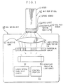
- FIG. 1 is a block diagram for illustrating the configuration of an optical system for transferring an imprint of a seal making device of the present invention.
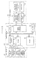
- FIG. 2 is a block diagram for illustrating the configuration of an electrical system of the seal making device of the present invention.
- FIG. 3 is a perspective view of the appearance of a seal making device of the present invention.
- FIG. 4 is a flowchart for illustrating an imprint-figure-information input operation of the seal making device of the present invention.
- FIG. 5 is a flowchart for illustrating a process of transferring an imprint figure to the resin member of the seal making device of the present invention.
- FIG. 6 is a schematic sectional view of an example of the modification of a light source of the seal making device of the present invention.
- FIG. 7 is a schematic sectional view of another example of the modification of the light source of the seal making device of the present invention.
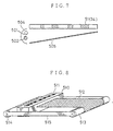
- FIG. 8 is a schematic perspective view of an example of the modification of a liquid crystal panel portion for transferring the imprint of the seal making device of the present invention.
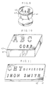
- FIG. 9 is a perspective view of a stamp made by the seal making device of the present invention.
- FIG. 10 is a perspective view of an example of a door plate or a badge indicating a company, which is made by the seal making device of the present invention.
- FIG. 11 is a perspective view of a name plate made by the seal making device of the present invention.
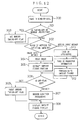
- FIG. 12 is a flowchart for illustrating a fundamental process to be performed by a control portion of the preferred embodiment of the present invention.
- FIG. 13 is a block diagram for illustrating the configuration of an electrical system of the preferred embodiment of the present invention.
- FIG. 14 is a perspective view of the appearance of a seal making device in the case of the preferred embodiment of the present invention.
- FIG. 15 is a diagram for illustrating problems to be solved by the preferred embodiment of the present invention.
- This seal making device embodying the present invention comprises a main body 40 of a seal and a seal making unit 45. Further, the seal making unit is primarily comprised of an electrical system of FIG. 2 (which further comprises an information processing portion and an imprint transfer controlling portion) and an optical system for transferring an imprint, which is shown in FIG. 1. Incidentally, FIG. 1 also shows the structure of the main body 40 of a seal. Moreover, FIG. 3 is a perspective view of the appearance of this seal making device embodying the present invention. FIGS. 4 and 5 are flowcharts for illustrating fundamental processes for making a seal.
- This electrical system is mainly used to input imprint figure information and control the optical system for transferring an imprint and corresponds to a kind of an information processing system. Further, similarly as in the cases of other general purpose electronic information processing systems, this electrical system primarily comprises an input portion 10, a control portion 20 and an output portion 30.
- the control portion 20 performs a processing according to information input from the input portion 10 and a current processing stage or the like and controls the optical system for transferring an imprint, through the output portion 30 according to a result of the processing.
- the input portion 10 comprises a keying input portion 11 which is provided with depressing keys, dialing keys or the like, an image reading portion 12 and a kind-of-seal detecting sensor 13.
- the keying input portion 11 is operative to generate character code data and various control data to be given to the control portion 20.
- the image reading portion 12 is operative to read a draft and give image data to the control portion 20.
- the kind-of-seal detecting sensor 13 is operative to detect a kind of the seal loaded into the device and give kind-of-seal information to the control portion 20.
- each of the main body of the seal and a jig for loading thereof has a physical identification element such as a hole prescribing a kind of the seal.
- the kind-of-seal detecting sensor 13 reads the physical element and outputs the kind-of-seal information.
- the kind-of-seal sensor 13 may be omitted.
- the output portion 30 is comprised of a drive circuit 31 for driving an ultraviolet irradiating light source 50 (to be described later), another drive circuit 32 for driving a liquid crystal panel portion 51 for transferring an imprint (to be described later) and a further drive circuit 33 for driving a display liquid crystal unit 34.
- a drive circuit 31 for driving an ultraviolet irradiating light source 50 to be described later
- another drive circuit 32 for driving a liquid crystal panel portion 51 for transferring an imprint to be described later
- a further drive circuit 33 for driving a display liquid crystal unit 34.
- Each of the drive circuits 31, 32 and 33 drives the corresponding portion or unit under the control of the control portion 20.
- the display liquid crystal unit 34 corresponds to a display unit of an information processing system and is used to display a guidance message for a maker of a seal, imprint figure information or the like.
- the ultraviolet irradiating light source 50 the liquid crystal panel 51 for transferring an imprint and drive control portions therefor will be described later (see FIG. 1).
- the control portion 20 is comprised of, for example, a microcomputer, in which a CPU 21, a ROM 22, a RAM 23, a character generator ROM (hereunder abbreviated as a CG-ROM) 24, an input portion interface 25 and an output portion interface 26 are connected with one anther through a system bus 27.
- a microcomputer in which a CPU 21, a ROM 22, a RAM 23, a character generator ROM (hereunder abbreviated as a CG-ROM) 24, an input portion interface 25 and an output portion interface 26 are connected with one anther through a system bus 27.
- ROM 22 there are stored various processing programs (see FIGS. 4 and 5) for making a seal, which should be executed by the CPU 21, a conversion table used for converting keyed code data into corresponding character codes and fixed data such as dictionary data used for kana-kanji conversion (for instance, converting a "kana"-code to a "kanji”-code) in the case of effecting Japanese word processing.
- the RAM 23 is used by the CPU 21 as a working memory, in which user input fixed data is stored.
- the CG-ROM 24 stores data representing dot-patterns of characters and symbols, which are prepared in the seal making unit. When inputting code data specifying a character or a symbol, the CG-ROM 24 outputs data representing a dot-pattern corresponding to the specified character or symbol.
- a CG-ROM for displaying data and another CG-ROM for transferring an imprint may be provided separately from each other.
- the input portion interface 25 interfaces the input portion 10 with the control portion 20.
- the output portion interface 26 interfaces the output portion 30 with the control portion 20.
- the CPU 21 executes a processing program, which is determined according to an input signal issued from the input portion 10 and to a current stage of a processing, by utilizing the RAM 23 as a working storage area and, if necessary, properly using the fixed data stored in the ROM 22 or the RAM 23. Further, the CPU 21 causes the display liquid crystal unit 34 to display a processing situation and a result of the processing. Moreover, the CPU 21 drives the ultraviolet irradiating light source 50 and the liquid crystal panel portion 51 for transferring an imprint to make a seal.
- the main body 40 of the seal is comprised of a cylindrical stock 41 (which may be made of material other than wood), a sponge member which is mounted on an end portion of this stock 41 and is made of elastic material such as sponge or rubber suitable for absorbing a pressure and a resisting force when stamping paper with a seal and for making a convex portion of a seal face member get to fit well with the surface of paper and the seal face member 42 having a plate-like shape and provided on the surface of this sponge member 43.
- the seal face member 42 is comprised of a base layer 42a, which is insensitive to ultraviolet light, and an ultraviolet light setting resin layer 42b which is exposed to ultraviolet light.
- the thickness of the ultraviolet setting resin layer 42b is set to be equal to the height of a projection (namely, the convex portion) of the seal face member, to which seal or stamp ink adheres.
- the main body 40 of the seal is detachably mounted on the seal making unit 45 by a fixture mechanism (not shown). Further, the main body 40 of the seal having, for example, a rectangular section is mounted thereon such that a corner of the rectangle is coincident with a reference point of an orthogonal coordinate system. Furthermore, the main body 40 of the seal having a circular or ellipsoidal section is loaded by way of a fixture jig into the seal making unit 45, similarly as in the case of the main body 40 of the seal having a rectangular section. Incidentally, it is preferable that when the main body of the seal is loaded thereinto, ultraviolet light is prevented from coming through the device.
- the optical system for transmitting an imprint is comprised of the ultraviolet irradiating light source 50, the liquid panel portion 51 for transferring an imprint, which can control the transmission of ultraviolet and an objective lens 52 (which is often implemented by a complex or compound lens), and the source 50, the panel portion 51 and the lens 52 are arranged in this order.
- the ultraviolet setting resin layer 42b is an object to be irradiated.
- a diffusing plate may be provided between the light source 50 and the main body 40 of the seal, with the intention of uniforming the light rays.
- the ultraviolet irradiating light source (for example, a fluorescent lamp) 50 performs light emission only for a period of time when an on-command is given by the light source drive circuit 31 thereto. This period of time for light emission is set to be a time enough for causing a setting in the ultraviolet setting resin layer 42b.
- the ultraviolet irradiating light source 50 may be turned on or off by using an on-off switch or the like. Namely, the turning-on or turning-off of the ultraviolet irradiating light source 50 may be controlled by the CPU 21.
- each of cells placed in a two-dimensional arrangement are established by the liquid crystal panel drive circuit 32 under the control of the control portion 20.
- Each cell set in an on-state transmits ultraviolet light emitted from the light source 50.
- each cell set in an off-state prevents the transmission of the ultraviolet light emitted by the light source 50.
- the turning-on and turning-off of each cell are effected such that an image represented by the cells becomes similar to the imprint figure, as will be explained later in the description of an operation of the device.
- an ultraviolet image transmitted by the liquid crystal panel portion 51 for transferring an imprint becomes an image of the imprint figure.
- a liquid crystal panel is, generally, used in a display device and transmits visible light.
- a liquid crystal panel of the type that uses an ultraviolet region as a transmission region.
- the liquid crystal panel of such a type may be applied by itself or together with an ultraviolet transmitting filter to the liquid crystal panel portion 51 for transferring an imprint.
- the objective lens 52 is used to form an ultraviolet image of the imprint figure on the ultraviolet setting resin layer 42b. Further, it is preferable that the focal plane of the objective lens 52 is slightly shifted from the surface of the ultraviolet setting resin layer 42b. If the focal plane of the objective lens 52 exactly coincides with the surface of the ultraviolet setting resin layer 42b, the contour of the imprint figure becomes rugged upon arranging the cells of the liquid crystal panel portion 51 for transferring an imprint. However, bundles of light emitted from the cells slightly overlap with one another if the focal plane of the objective lens 52 is shifted slightly from the surface of the ultraviolet setting resin layer 42b. Thereby, the contour of the imprint figure can be prevented from becoming notched.
- portions other than a set or hardened portion of the ultraviolet setting resin layer 42b can be removed therefrom by using a predetermined kind of liquid (for example, water (incidentally, some kind of gas may be used instead of liquid)).
- a predetermined kind of liquid for example, water (incidentally, some kind of gas may be used instead of liquid)
- the seal making device having the electrical system of FIG. 2 and the optical system of FIG. 1 present an appearance as illustrated in, for instance, FIG. 3.
- the keying input portion 11, the display liquid crystal unit 34 and a fixture mechanism 55 for the main body 40 of the seal are placed at appropriate positions on a console panel, respectively.
- the image reading portion 12 is connected to a main body 56 of the seal making unit.
- the CPU 21 When it is ordered by the keying input portion 11 that an operation of reading the imprint figure information should be performed, the CPU 21 starts executing a program which is stored in the ROM 22 and is used for performing the operation of reading the imprint figure information as illustrated in FIG. 4. First, the CPU 21 causes the display liquid crystal unit 34 to display kind-of-seal information and reads the kind-of-seal information selected by a maker of a seal or an operator through the keying input portion 11 (step 100).
- kinds of seals are defined on the basis of the shape of the face of the seal (for example, a rectangle, a circle and an ellipsoid) and the size of the face of the seal (for instance, a large size, a middle size and a small size) and that the kinds of seals to be handled by this seal making device are predetermined.
- the CPU 21 causes the display liquid crystal unit 34 to display a message inquiring which of a keying input method and an image input method the maker chooses. Then, the CPU 21 reads information on the input method selected by the maker from the keying input portion 11 and identifies the selected input method (step 101).
- the CPU 21 causes the display liquid crystal unit 34 to display a message requesting the maker to set a draft in the image reading portion 12 and subsequently activate the image reading portion 12. Thereafter, the CPU 21 takes in image data read by the image reading portion 12 (step 102). Subsequently, the CPU 21 instructs the display liquid crystal unit 34 to display the read image and the contour of the face of a seal of the indicated kind while superposing the read image on the contour of the face. Further, the CPU 21 requests the maker to specify a portion of the read image to be used as an imprint figure. Then, the CPU 21 takes in data representing the indicated part to be used as the imprint figure. Moreover, the CPU 21 instructs the display liquid crystal unit 34 to display that part as an imprint figure image. Then, an operation of inputting the imprint figure information is terminated (step 103).
- the maker manipulates a cursor key
- the image of the contour of the face corresponding to the indicated kind of a seal is move to the direction indicated by the cursor key.
- a part of the read image surrounded by the displayed contour of the face of the seal at that time is input as an indicated imprint figure.
- the CPU 21 causes the display liquid crystal unit 34 to display a message requesting the maker to specify attribute information representing the attributes of the imprint figure and thereafter takes in the specified attribute information of the imprint figure (step 104).
- the information representing the attributes of the imprint figure includes, for example, information concerning whether or not the imprint is surrounded by a frame, information regarding which of column writing and horizontal writing should be used, information representing the number of lines, information representing the (absolute or relative) size of each character, information indicating which of what is called a negative engraving (corresponding to a reverse display) and what is called a positive engraving (corresponding to a non-reverse display) should be employed, information representing a typeface, information concerning whether or not the imprint figure should be intentionally made to be blurred as a whole, and information indicating the size of the contour of the imprint figure portion.
- the CPU 21 takes in these kinds of information as the attribute information.
- some attributes can not be designated due to constraints on, for example, the size of a designated seal. For instance, in the case of a small seal, a multi-line pattern is inhibited.
- the CPU 21 prompts the maker with an indication displayed by the display liquid crystal unit 34 to input character information.
- the character information inputted through the keying taken portion 11 is taken by the CPU 21 by performing a processing similar to that performed in an information processing system such as a word processor (step 105).
- the indication displayed in this input processing is not a representation like an imprint figure image.
- the CPU 21 performs a conversion processing on the input character information according to the indicated various attributes and subsequently, the CPU 21 instructs the display liquid crystal unit 34 to display the converted information as an imprint figure image in order to permit the maker to verify the imprint figure image. Then, the operation of inputting the imprint figure information is finished (step 106).
- the indication of the input characters may be changed to the indication of the imprint figure image of characters having been input until then and vice versa in response to the keying operation effected by the user.
- the maker of the seal may initiate an operation of transferring the imprint figure to the seal face member 42 immediately.
- the imprint figure may be once stored in the RAM 23 (or an external storage device).
- the maker can instruct a transfer of the imprint figure onto the seal face member 42 by using the keying input portion 11.
- the CPU 21 can start executing a transfer processing program of FIG. 5, which is stored in the ROM 22, for transferring the imprint figure onto the seal face member 42.
- the CPU 21 receives information delivered from the kind-of-seal detecting sensor 13 to verify whether or not the main body 40 of the seal is loaded into the seal making unit 45 and whether or not the kind of the main body 40 of the seal loaded into the unit 45 is matched with the indicated kind of the seal (step 200).
- the CPU 21 performs an error processing, namely, the CPU 21 instructs the display liquid crystal unit 34 to display a message requesting the loading of a correct kind of a seal or the replacement of the main body 40 of the seal (step 201).
- each of the cells respectively corresponding to portions of the imprint figure are set to be in an on-state and in contrast, each of the cells corresponding to the background of the imprint figure are set to be in an off-state.
- the CPU 21 causes the ultraviolet irradiating light source 50 to emit light for a predetermined period of time (step 203).
- the CPU 21 instructs the display liquid crystal unit 34 to display messages indicating that the irradiation of the ultraviolet light is finished and that the ultraviolet setting resin layer 42b of the main body 40 of the seal should be washed by the predetermined kind of liquid (or water) and finishes the operation of transferring the imprint figure, which comprises the sequence of the steps (step 204).
- the maker Upon completion of the transfer processing (namely, the setting processing), the maker washes the ultraviolet setting resin layer 42b by using the predetermined kind of liquid. Thereby, portions of the layer 42b other than the hardened portions thereof are removed therefrom. As the result, convex and concave portions composing the relief or intaglio imprint figure are formed. Thus the seal is completed.
- the main body 40 of the seal is once again loaded into the seal making unit 45 and further ultraviolet light is irradiated again onto the main body 40 thereof to ensure the hardening of the setting resin layer.
- each of the cells of the liquid crystal panel portion 51 is put into an open state.
- FIGS. 9 to 11 illustrate examples of a seal, a door plate and a name plate made by this seal making device, respectively.
- FIG. 9 illustrates the example of the seal (or stamp). As shown in this figure, the seal face member 42, on the surface of which an alphabetical relief pattern "A & B" is formed, is fixed through the sponge member 43 to the stock having an ellipsoidal section.
- FIG. 10 illustrates the example of the door plate or badge indicating a company, which is not required to have elasticity unlike the stamp.
- the seal face member 42 on which the alphabetical relief pattern is formed, is directly fixed to the stock 41.
- the relief figure as shown in FIG. 10 is formed on each of the front and back surfaces of the door.
- FIG. 11 illustrates the example of the name plate which does not need to have elasticity.
- the seal face member 42 on which the alphabetical relief pattern is formed, is directly fixed to the stock 41.
- the color of the ultraviolet setting resin layer 42b is made to be different from the color of the base layer 42a and the stock (or base plate) 41.
- a border inhibiting instruction means for instructing the inhibition of adding of a border to an imprint figure is provided in the device.
- the information processing means automatically adds the border to the input imprint figure to make a final imprint figure except a case where the border inhibiting instruction means instructs that a border should not be added to an imprint figure.
- a border inhibiting instruction means for instructing the inhibition of adding of a border to an imprint figure is similarly provided in the device.
- an applying means having predetermined physical characteristics performs an application operation on a resin seal face member by adding a border to an imprint figure, except a case where the border inhibiting instruction means instructs that the border should not be added to the imprint figure.
- a border instruction means for instructing whether or not a border should be added to an imprint figure is provided in the device.
- a border instruction means for instructing whether or not a border should be added to an imprint figure is similarly provided in the device.
- the border inhibiting instruction means instructs that a border should be added to an imprint figure
- an applying means having predetermined physical characteristics performs an application operation on a resin seal face member by adding a border to an imprint figure.
- the seal making device comprises of the main body of a seal and a seal making unit.
- the seal making unit is primarily comprised of an electrical system of FIG. 13 (namely, an information processing portion and an imprint transfer controlling portion) and a mechanismic optical system as illustrated in the device described above.
- This electrical system is basically similar to that illustrated in the case of each of the first to sixth embodiments except that a border taking-off instructing portion 14 is newly provided in the system.
- the border taking-off instructing portion 14 of a keying input porion 11 is newly provided in the system of this embodiment.
- a border is automatically added to an imprint figure input by the maker of the seal, as will be described later.
- the border taking-off instructing portion 14 is operated when inhibiting an automatic addition of the border to the imprint figure. Such an instruction is effective if issued only for a single seal which will be made hereafter.
- the border taking-off instructing portion 14 may be implemented by, for example, an automatic reset push-button.
- the CPU 21 when it is ordered by the keying input portion 11 that an operation of reading the imprint figure information should be performed, the CPU 21 starts executing a program which is stored in the ROM 22 and is used for performing the operation of reading the imprint figure information as illustrated in FIG. 12. First, the CPU 21 causes the display unit 33 to display kind-of-seal information and reads the kind-of-seal information selected by the maker of a seal through the keying input portion 11 (step 300).
- kinds of seals are defined on the basis of the shape of the face of the seal (for example, a rectangle, a circle and an ellipsoid) and the size of the face of the seal (for instance, a large size, a middle size and a small size) and that the kinds of seals to be handled by this seal making device are preliminarily determined.
- the CPU 21 causes the display unit 33 to display a message indicating that if a border is unnecessary, the maker should first operate the border taking-off instructing portion 14 and thereafter should indicate which of a keying input method and an image input method the maker chooses and that if a border is necessary, the maker should immediately indicate which of a keying input method and an image input method the maker chooses. Then, the CPU 21 reads information input by the maker and makes a judgment on the contents of the input information (steps 301 to 303). In the case where the border taking-off instructing portion 14 is operated, a border taking-off flag is set and the CPU makes a judgement on a method for inputting imprint figure information (step 303).
- the CPU 21 causes the display unit 33 to display a message requesting the maker to set a draft in the image reading portion 12 and subsequently activate the image reading portion 12. Thereafter, the CPU 21 takes in image data read by the image reading portion 12 (step 304). Subsequently, the CPU 21 instructs the display unit 33 to display the read image and the contour of the face of a seal of the indicated kind by superposing the read image on the contour of the face. Further, the CPU 21 requests the maker to specify a portion of the read image to be used as an imprint figure. Then, the CPU 21 takes in data representing the indicated part to be used as the imprint figure (step 305).
- the maker manipulates a cursor key
- the image of the contour of the face corresponding to the indicated kind of a seal is move to the direction indicated by the cursor key.
- a part of the read image surrounded by the displayed contour of the face of the seal at that time is input as an indicated imprint figure.
- the value of the border taking-off flag is verified (step 306).
- a border determined according to the kind of the seal or the like at that time is added to the imprint figure.
- a final imprint pattern is obtained.
- the CPU instructs the display unit 33 to display the final imprint pattern. Then, an operation of inputting the imprint figure information is terminated (steps 307 and 308).
- the border taking-off flag indicates that the maker denies a border to an imprint figure (namely, in the case where the border taking-off flag is set)
- the border taking-off flag is reset in order to enable the device to add a border to another imprint figure when taking in such an imprint figure later.
- the CPU instructs the display unit 33 to display an input imprint figure without a border as a final imprint pattern. Then, an operation of inputting the imprint figure information is terminated (steps 309 and 308).
- the seal making device is suitable for easily and quickly making a desired relief or intaglio figure plate such as a seal or stamp, a name plate and a door plate, regardless of whether the relief or intaglio figure plate is for business use or for private use, and independent of the size and shape of the relief or intaglio figure.
- a desired relief or intaglio figure plate such as a seal or stamp, a name plate and a door plate
Landscapes
- Engineering & Computer Science (AREA)
- Manufacturing & Machinery (AREA)
- Mechanical Engineering (AREA)
- Physics & Mathematics (AREA)
- General Physics & Mathematics (AREA)
- Manufacture Or Reproduction Of Printing Formes (AREA)
- Collating Specific Patterns (AREA)
- Photosensitive Polymer And Photoresist Processing (AREA)
- Shaping Of Tube Ends By Bending Or Straightening (AREA)
- Printing Methods (AREA)
- Illuminated Signs And Luminous Advertising (AREA)
Description
- This invention generally relates to a seal making device and more particularly to a seal making device, by which a person other than an expert and a professional can make a desired seal easily. In the instant specification, the term "seal making device" should be construed as including a relief or intaglio figure plate making device for making a plate, one or both of the front and back sides of which are engraved with relief or intaglio figures or patterns.
- Seals in a broad sense, which include a seal engraved with a person's surname or full name, a larger stamp engraved with a mark indicating an office to which individuals belong and a signet, are usually made by experts or professionals. Further, no matter whether such seals are hand-made or machine-made, each of them is usually made by selectively incising a part of the surface of one end of a cylindrical or plate-like body.
- Incidentally, a seal is sometimes made by forming, for example, a mold of a resin, on a surface of which is engraved with a relief or intaglio figure projecting or hollowing in inverse relation to the unevenness of the intaglio or relief figure engraved on a surface of the seal, and thereafter injecting a fluid material such as rubber into the mold and then solidifying the fluid material to form an engraved member having substantially the same unevenness as such an intaglio figure.
- However, there are many kinds of seals which corporations and individuals wish to have. For instance, a seal indicating an addressee to which letters are frequently mailed, a stamp indicating a title of account, and a seal which is given to a new employee, are often required by them. In case of requesting an expert or a professional to make such a seal, stamp or badge, money matters and the term of making a seal or the like sometimes come into problem.
- Further, recently, relief or intaglio figures are sometimes formed on the surfaces of, for example, a door-plate mounted on a door of a person's private room, a plate put up at an entrance of a building and a decoration worn on a person's chest, similarly as in the aforesaid cases of the seals or the like. In such cases, similar matters and problems often occur.
- Therefore, there is a demand for a person other than an expert and a professional to make a desired seal or the like easily. Previously, a seal making device (strictly speaking, a seal making kit), by which a person other than an expert and a professional can make a seal, has been on the market.
- U.S. Patent No. 4,714,957 discloses: (1) an apparatus for making a stamp, comprising image data outputting means composed of a liquid crystal TV circuit and an image data processing circuit, a photosensitive resin layer, a light source emitting photoactive light rays and being disposed oppositely to the photosensitive resin layer, a liquid crystal display panel disposed between the light source and the photosensitive resin layer, and a projection lens placed between the liquid crystal display panel and the photosensitive resin layer; (2) an apparatus for making a stamp, comprising a photosensitive resin layer formed on a substrate, means for producing an imprint figure to be formed on the photosensitive resin layer, and means for writing the imprint figure on the photosensitive resin layer by irradiating the photosensitive resin layer with photoactive light rays; and (3) an apparatus for making a stamp, comprising a photosensitive resin intended to form a stamp, means for making an exposure film to be used in making a stamp, and exposure means for irradiating photoactive light rays on the photosensitive resin through the exposure film.
- Japanese Patent Application Laying-open No. sho 62-54254 discloses a method for making a relief, comprising the steps of applying a water-soluble photosensitive resin onto a substrate, drying the applied photosensitive resin layer, performing recording with an ink onto the dried photosensitive resin layer, and thereafter setting a part of the photosensitive resin layer other than a part of the photosensitive resin layer, recorded with the ink, by irradiating radiant rays on the photosensitive resin layer.
- Japanese Patent Application Laying-open No. Hei 2-179783 discloses a method for making a seal, comprising the steps of exposing a photosensitive resin while using a heat transferring medium, which has been used for performing printing onto a substance to be transferred and comprises a transparent film covered with a heat transferring ink, as a negative, and removing an unexposed portion of the photosensitive resin.
- This conventional seal making device (not shown) employs a film of the ultraviolet sensitive type, an ultraviolet irradiating unit, a planar ultraviolet setting resin member and a stock. Further, a seal is made by using this conventional seal making device as will be described later. Incidentally, the ultraviolet irradiating unit comprises a casing in which an ultraviolet fluorescent lamp is provided, a timer by which a user sets a time to light the ultraviolet lamp, a transparent plate mounted on the top surface of the casing and transmitting ultraviolet light, and an openable lid for preventing the transmitted ultraviolet light from coming out of the transparent plate. Furthermore, the ultraviolet setting resin member comprises a base layer, which is not sensitive to ultraviolet light, and an ultraviolet setting resin layer. Incidentally, the base layer is thinner than the ultraviolet setting resin layer.
- In the case of making a seal by using this conventional seal making device, first, characters or patterns (hereunder referred to as an imprint figure), which should be transferred onto paper if the seal is completed and the completed seal is impressed thereon, are drafted on ultraviolet transmittible paper such as tracing paper and thus an original picture of the imprint figure is drawn up.
- Thereafter, the original picture and the film of the ultraviolet sensitive type are piled up on the transparent plate of the ultraviolet irradiating unit. Then, the lid is closed. Further, a time for irradiating ultraviolet light is set according to the quality of paper, on which the original picture is drafted, by using the timer. Subsequently, ultraviolet light is irradiated from the ultraviolet lamp onto the film for the set time. The film exposed in this manner is then washed by predetermined kind of liquid (in the case of the device being on the market, this liquid is water) so as to obtain a negative film on which the imprint figure is reversed. Namely, on this negative film, the dark tone portions of the imprint figure appear transparent to ultraviolet light and the remaining portions thereof appear brown (namely, the color obtained as the result of ultraviolet absorption).
- Next, this negative film and the ultraviolet setting resin member are piled up on the transparent plate of the ultraviolet irradiating unit. Then, the lid is closed and ultraviolet light is irradiated from the ultraviolet lamp onto the film for a predetermined time. This results in that portions (corresponding to the dark tone portions of the imprint figure), on which the ultraviolet light is irradiated, of the ultraviolet setting resin member are hardened. In contrast, the remaining portions of the ultraviolet setting resin member do not become hard. Upon completion of such a setting processing, the ultraviolet setting resin member is washed by the predetermined kind of liquid (in the case of the device being on the market, this liquid is water) to remove the portions thereof, which do not become hard. Thereby, the engraved member, in which the hardened portions (corresponding to the imprint figure) of the ultraviolet setting resin layer project from the base layers of the remaining portions of the ultraviolet setting resin member, is completed. Subsequently, the fixation of the engraved member completed in this way is performed by further irradiating ultraviolet light thereon.
- Then, this engraved member is fitted to the stock. Thus the seal is completed.
- This conventional seal making device, however, has drawbacks in that a maker should perform a very large number of operations which include the operation of making an original picture and that thus the efficiency is low and the time required for making a seal is long.
- These drawbacks are mainly due to the fact that although information on an imprint figure is included in an original picture, this information can not be utilized directly for making the engraved member, namely, a negative film should be made as an intermediate product.
- Further, excepting a case that an original picture is made by handwriting an imprint figure intentionally, when the original picture is made by using a predetermined typestyle or typeface, a maker comes to use what is called a word processor or the like. Moreover, it becomes necessary to copy the imprint figure made by the word processor onto ultraviolet transmittible paper by using an electronic copying machine or the like. Thus, the operation of making an original picture requires much time and trouble.
- Additionally, it is also necessary to set an ultraviolet irradiating time according to the thickness of ultraviolet transmittible paper and the dark tone of a draft of the original picture. This operation requires skill to some extent.
- The present invention is accomplished in the light of the aforesaid problems of the conventional seal making device. It is, accordingly, an object of the present invention to provide a seal making device by which a person other than a specialist in making a seal can make a desired seal easily in a short time.
- The aforesaid object of the present invention is achieved by an apparatus for making a seal according to
claim 1 or 2. - The imprint figure information generating unit generates an imprint figure information signal representing a relief or intaglio figure used as a source of the imprint figure by, for example, reading an image of the relief or intaglio figure. Then, the imprint figure transfer controlling unit gives physical stimulation such as ultraviolet light to the resin layer. This results in change of the characteristics of a portion of the resin layer having suffered the physical stimulation. Thereafter, one of a portion of the resin layer having suffered the physical stimulation, and another portion thereof having suffered no physical stimulation is removed by the physical or chemical action of washing. As a consequence, the relief or intaglio figure is formed on the surface of the resin member in accordance with the imprint figure information.
- Therefore, in the case of the device of the present invention, it is not necessary to make an intermediate product such as a negative film. Thus a seal can be made easily and quickly.
- FIG. 1 is a block diagram for illustrating the configuration of an optical system for transferring an imprint of a seal making device of the present invention. FIG. 2 is a block diagram for illustrating the configuration of an electrical system of the seal making device of the present invention. FIG. 3 is a perspective view of the appearance of a seal making device of the present invention. FIG. 4 is a flowchart for illustrating an imprint-figure-information input operation of the seal making device of the present invention. FIG. 5 is a flowchart for illustrating a process of transferring an imprint figure to the resin member of the seal making device of the present invention. FIG. 6 is a schematic sectional view of an example of the modification of a light source of the seal making device of the present invention. FIG. 7 is a schematic sectional view of another example of the modification of the light source of the seal making device of the present invention. FIG. 8 is a schematic perspective view of an example of the modification of a liquid crystal panel portion for transferring the imprint of the seal making device of the present invention. FIG. 9 is a perspective view of a stamp made by the seal making device of the present invention. FIG. 10 is a perspective view of an example of a door plate or a badge indicating a company, which is made by the seal making device of the present invention. FIG. 11 is a perspective view of a name plate made by the seal making device of the present invention.
- FIG. 12 is a flowchart for illustrating a fundamental process to be performed by a control portion of the preferred embodiment of the present invention. FIG. 13 is a block diagram for illustrating the configuration of an electrical system of the preferred embodiment of the present invention. FIG. 14 is a perspective view of the appearance of a seal making device in the case of the preferred embodiment of the present invention. FIG. 15 is a diagram for illustrating problems to be solved by the preferred embodiment of the present invention.
- Hereinafter, a seal making device, will be described in detail by referring to the accompanying drawings.
- This seal making device embodying the present invention comprises a
main body 40 of a seal and aseal making unit 45. Further, the seal making unit is primarily comprised of an electrical system of FIG. 2 (which further comprises an information processing portion and an imprint transfer controlling portion) and an optical system for transferring an imprint, which is shown in FIG. 1. Incidentally, FIG. 1 also shows the structure of themain body 40 of a seal. Moreover, FIG. 3 is a perspective view of the appearance of this seal making device embodying the present invention. FIGS. 4 and 5 are flowcharts for illustrating fundamental processes for making a seal. - First, the electrical system of this embodiment of the present invention will be described hereinbelow by referring to FIG. 2.
- This electrical system is mainly used to input imprint figure information and control the optical system for transferring an imprint and corresponds to a kind of an information processing system. Further, similarly as in the cases of other general purpose electronic information processing systems, this electrical system primarily comprises an
input portion 10, acontrol portion 20 and anoutput portion 30. Thecontrol portion 20 performs a processing according to information input from theinput portion 10 and a current processing stage or the like and controls the optical system for transferring an imprint, through theoutput portion 30 according to a result of the processing. - The
input portion 10 comprises a keyinginput portion 11 which is provided with depressing keys, dialing keys or the like, animage reading portion 12 and a kind-of-seal detecting sensor 13. The keyinginput portion 11 is operative to generate character code data and various control data to be given to thecontrol portion 20. Further, theimage reading portion 12 is operative to read a draft and give image data to thecontrol portion 20. Moreover, the kind-of-seal detecting sensor 13 is operative to detect a kind of the seal loaded into the device and give kind-of-seal information to thecontrol portion 20. For example, each of the main body of the seal and a jig for loading thereof has a physical identification element such as a hole prescribing a kind of the seal. The kind-of-seal detecting sensor 13 reads the physical element and outputs the kind-of-seal information. Incidentally, the kind-of-seal sensor 13 may be omitted. - The
output portion 30 is comprised of adrive circuit 31 for driving an ultraviolet irradiating light source 50 (to be described later), anotherdrive circuit 32 for driving a liquidcrystal panel portion 51 for transferring an imprint (to be described later) and afurther drive circuit 33 for driving a displayliquid crystal unit 34. Each of thedrive circuits control portion 20. Further, the displayliquid crystal unit 34 corresponds to a display unit of an information processing system and is used to display a guidance message for a maker of a seal, imprint figure information or the like. - Incidentally, the ultraviolet irradiating
light source 50, theliquid crystal panel 51 for transferring an imprint and drive control portions therefor will be described later (see FIG. 1). - The
control portion 20 is comprised of, for example, a microcomputer, in which aCPU 21, aROM 22, aRAM 23, a character generator ROM (hereunder abbreviated as a CG-ROM) 24, aninput portion interface 25 and an output portion interface 26 are connected with one anther through asystem bus 27. - In the
ROM 22, there are stored various processing programs (see FIGS. 4 and 5) for making a seal, which should be executed by theCPU 21, a conversion table used for converting keyed code data into corresponding character codes and fixed data such as dictionary data used for kana-kanji conversion (for instance, converting a "kana"-code to a "kanji"-code) in the case of effecting Japanese word processing. - Further, the
RAM 23 is used by theCPU 21 as a working memory, in which user input fixed data is stored. - Moreover, the CG-
ROM 24 stores data representing dot-patterns of characters and symbols, which are prepared in the seal making unit. When inputting code data specifying a character or a symbol, the CG-ROM 24 outputs data representing a dot-pattern corresponding to the specified character or symbol. Incidentally, a CG-ROM for displaying data and another CG-ROM for transferring an imprint may be provided separately from each other. - Furthermore, the
input portion interface 25 interfaces theinput portion 10 with thecontrol portion 20. On the other hand, the output portion interface 26 interfaces theoutput portion 30 with thecontrol portion 20. - Additionally, the
CPU 21 executes a processing program, which is determined according to an input signal issued from theinput portion 10 and to a current stage of a processing, by utilizing theRAM 23 as a working storage area and, if necessary, properly using the fixed data stored in theROM 22 or theRAM 23. Further, theCPU 21 causes the displayliquid crystal unit 34 to display a processing situation and a result of the processing. Moreover, theCPU 21 drives the ultraviolet irradiatinglight source 50 and the liquidcrystal panel portion 51 for transferring an imprint to make a seal. - Next, the configurations of the optical system and the main body of a seal will be described hereinbelow by referring to FIG. 1.
- The
main body 40 of the seal is comprised of a cylindrical stock 41 (which may be made of material other than wood), a sponge member which is mounted on an end portion of thisstock 41 and is made of elastic material such as sponge or rubber suitable for absorbing a pressure and a resisting force when stamping paper with a seal and for making a convex portion of a seal face member get to fit well with the surface of paper and theseal face member 42 having a plate-like shape and provided on the surface of thissponge member 43. Theseal face member 42 is comprised of abase layer 42a, which is insensitive to ultraviolet light, and an ultraviolet light setting resin layer 42b which is exposed to ultraviolet light. The thickness of the ultraviolet setting resin layer 42b is set to be equal to the height of a projection (namely, the convex portion) of the seal face member, to which seal or stamp ink adheres. - The
main body 40 of the seal is detachably mounted on theseal making unit 45 by a fixture mechanism (not shown). Further, themain body 40 of the seal having, for example, a rectangular section is mounted thereon such that a corner of the rectangle is coincident with a reference point of an orthogonal coordinate system. Furthermore, themain body 40 of the seal having a circular or ellipsoidal section is loaded by way of a fixture jig into theseal making unit 45, similarly as in the case of themain body 40 of the seal having a rectangular section. Incidentally, it is preferable that when the main body of the seal is loaded thereinto, ultraviolet light is prevented from coming through the device. - The optical system for transmitting an imprint is comprised of the ultraviolet irradiating
light source 50, theliquid panel portion 51 for transferring an imprint, which can control the transmission of ultraviolet and an objective lens 52 (which is often implemented by a complex or compound lens), and thesource 50, thepanel portion 51 and thelens 52 are arranged in this order. Further, the ultraviolet setting resin layer 42b is an object to be irradiated. Incidentally, a diffusing plate may be provided between thelight source 50 and themain body 40 of the seal, with the intention of uniforming the light rays. - The ultraviolet irradiating light source (for example, a fluorescent lamp) 50 performs light emission only for a period of time when an on-command is given by the light
source drive circuit 31 thereto. This period of time for light emission is set to be a time enough for causing a setting in the ultraviolet setting resin layer 42b. Incidentally, the ultraviolet irradiatinglight source 50 may be turned on or off by using an on-off switch or the like. Namely, the turning-on or turning-off of the ultraviolet irradiatinglight source 50 may be controlled by theCPU 21. - The on-state and off-state of each of cells placed in a two-dimensional arrangement are established by the liquid crystal
panel drive circuit 32 under the control of thecontrol portion 20. Each cell set in an on-state transmits ultraviolet light emitted from thelight source 50. In contrast, each cell set in an off-state prevents the transmission of the ultraviolet light emitted by thelight source 50. Here, the turning-on and turning-off of each cell are effected such that an image represented by the cells becomes similar to the imprint figure, as will be explained later in the description of an operation of the device. Thus, an ultraviolet image transmitted by the liquidcrystal panel portion 51 for transferring an imprint becomes an image of the imprint figure. - Incidentally, a liquid crystal panel is, generally, used in a display device and transmits visible light. However, there is a liquid crystal panel of the type that uses an ultraviolet region as a transmission region. The liquid crystal panel of such a type may be applied by itself or together with an ultraviolet transmitting filter to the liquid
crystal panel portion 51 for transferring an imprint. - The
objective lens 52 is used to form an ultraviolet image of the imprint figure on the ultraviolet setting resin layer 42b. Further, it is preferable that the focal plane of theobjective lens 52 is slightly shifted from the surface of the ultraviolet setting resin layer 42b. If the focal plane of theobjective lens 52 exactly coincides with the surface of the ultraviolet setting resin layer 42b, the contour of the imprint figure becomes rugged upon arranging the cells of the liquidcrystal panel portion 51 for transferring an imprint. However, bundles of light emitted from the cells slightly overlap with one another if the focal plane of theobjective lens 52 is shifted slightly from the surface of the ultraviolet setting resin layer 42b. Thereby, the contour of the imprint figure can be prevented from becoming notched. - Similarly as in the case of the conventional device, portions other than a set or hardened portion of the ultraviolet setting resin layer 42b can be removed therefrom by using a predetermined kind of liquid (for example, water (incidentally, some kind of gas may be used instead of liquid)).
- The seal making device having the electrical system of FIG. 2 and the optical system of FIG. 1 present an appearance as illustrated in, for instance, FIG. 3. In the case of the appearance of FIG. 3, the keying
input portion 11, the displayliquid crystal unit 34 and afixture mechanism 55 for themain body 40 of the seal are placed at appropriate positions on a console panel, respectively. Further, theimage reading portion 12 is connected to amain body 56 of the seal making unit. - Next, an example of an operation of reading the imprint figure information to be performed mainly by the
CPU 21 will be described hereunder by referring to FIG. 4. - When it is ordered by the keying
input portion 11 that an operation of reading the imprint figure information should be performed, theCPU 21 starts executing a program which is stored in theROM 22 and is used for performing the operation of reading the imprint figure information as illustrated in FIG. 4. First, theCPU 21 causes the displayliquid crystal unit 34 to display kind-of-seal information and reads the kind-of-seal information selected by a maker of a seal or an operator through the keying input portion 11 (step 100). Here, it is supposed that kinds of seals are defined on the basis of the shape of the face of the seal (for example, a rectangle, a circle and an ellipsoid) and the size of the face of the seal (for instance, a large size, a middle size and a small size) and that the kinds of seals to be handled by this seal making device are predetermined. - Next, the
CPU 21 causes the displayliquid crystal unit 34 to display a message inquiring which of a keying input method and an image input method the maker chooses. Then, theCPU 21 reads information on the input method selected by the maker from the keyinginput portion 11 and identifies the selected input method (step 101). - Here, if the image input method is selected, the
CPU 21 causes the displayliquid crystal unit 34 to display a message requesting the maker to set a draft in theimage reading portion 12 and subsequently activate theimage reading portion 12. Thereafter, theCPU 21 takes in image data read by the image reading portion 12 (step 102). Subsequently, theCPU 21 instructs the displayliquid crystal unit 34 to display the read image and the contour of the face of a seal of the indicated kind while superposing the read image on the contour of the face. Further, theCPU 21 requests the maker to specify a portion of the read image to be used as an imprint figure. Then, theCPU 21 takes in data representing the indicated part to be used as the imprint figure. Moreover, theCPU 21 instructs the displayliquid crystal unit 34 to display that part as an imprint figure image. Then, an operation of inputting the imprint figure information is terminated (step 103). - For example, when the maker manipulates a cursor key, the image of the contour of the face corresponding to the indicated kind of a seal is move to the direction indicated by the cursor key. When manipulating a defined key, a part of the read image surrounded by the displayed contour of the face of the seal at that time is input as an indicated imprint figure.
- In contrast, in a case where the keying input method is identified as an selected method for inputting the imprint figure information, the
CPU 21 causes the displayliquid crystal unit 34 to display a message requesting the maker to specify attribute information representing the attributes of the imprint figure and thereafter takes in the specified attribute information of the imprint figure (step 104). Further, the information representing the attributes of the imprint figure includes, for example, information concerning whether or not the imprint is surrounded by a frame, information regarding which of column writing and horizontal writing should be used, information representing the number of lines, information representing the (absolute or relative) size of each character, information indicating which of what is called a negative engraving (corresponding to a reverse display) and what is called a positive engraving (corresponding to a non-reverse display) should be employed, information representing a typeface, information concerning whether or not the imprint figure should be intentionally made to be blurred as a whole, and information indicating the size of the contour of the imprint figure portion. TheCPU 21 takes in these kinds of information as the attribute information. However, some attributes can not be designated due to constraints on, for example, the size of a designated seal. For instance, in the case of a small seal, a multi-line pattern is inhibited. - Thereafter, the
CPU 21 prompts the maker with an indication displayed by the displayliquid crystal unit 34 to input character information. Further, the character information inputted through the keying takenportion 11 is taken by theCPU 21 by performing a processing similar to that performed in an information processing system such as a word processor (step 105). Incidentally, the indication displayed in this input processing is not a representation like an imprint figure image. Further, when the termination of the inputting of the character information is directed, theCPU 21 performs a conversion processing on the input character information according to the indicated various attributes and subsequently, theCPU 21 instructs the displayliquid crystal unit 34 to display the converted information as an imprint figure image in order to permit the maker to verify the imprint figure image. Then, the operation of inputting the imprint figure information is finished (step 106). Incidentally, the indication of the input characters may be changed to the indication of the imprint figure image of characters having been input until then and vice versa in response to the keying operation effected by the user. - When finishing the operation of inputting the imprint figure information, the maker of the seal may initiate an operation of transferring the imprint figure to the
seal face member 42 immediately. Alternatively, the imprint figure may be once stored in the RAM 23 (or an external storage device). - For example, even in a situation that the imprint figure image is displayed on the screen of the display liquid crystal unit 34 (incidentally, such a situation includes a case that the imprint figure image stored in a storage device is read therefrom and displayed on the screen), the maker can instruct a transfer of the imprint figure onto the
seal face member 42 by using the keyinginput portion 11. At that time, theCPU 21 can start executing a transfer processing program of FIG. 5, which is stored in theROM 22, for transferring the imprint figure onto theseal face member 42. - The, first, the
CPU 21 receives information delivered from the kind-of-seal detecting sensor 13 to verify whether or not themain body 40 of the seal is loaded into theseal making unit 45 and whether or not the kind of themain body 40 of the seal loaded into theunit 45 is matched with the indicated kind of the seal (step 200). - At that time, if it is detected that no seal is loaded into the
unit 45 or that an erroneous kind of a seal is loaded thereinto, theCPU 21 performs an error processing, namely, theCPU 21 instructs the displayliquid crystal unit 34 to display a message requesting the loading of a correct kind of a seal or the replacement of themain body 40 of the seal (step 201). - In contrast, if the validity of the
main body 40 of the seal loaded into the unit is affirmed, the turning-on or turning-off of each of the cells of the liquidcrystal panel portion 51 is established according to the imprint figure which is a current object to be transferred (step 202). In the case of this embodiment, each of the cells respectively corresponding to portions of the imprint figure are set to be in an on-state and in contrast, each of the cells corresponding to the background of the imprint figure are set to be in an off-state. Thereafter, theCPU 21 causes the ultraviolet irradiatinglight source 50 to emit light for a predetermined period of time (step 203). Further, when the predetermined period of time has elapsed, theCPU 21 instructs the displayliquid crystal unit 34 to display messages indicating that the irradiation of the ultraviolet light is finished and that the ultraviolet setting resin layer 42b of themain body 40 of the seal should be washed by the predetermined kind of liquid (or water) and finishes the operation of transferring the imprint figure, which comprises the sequence of the steps (step 204). - Upon completion of the transfer processing (namely, the setting processing), the maker washes the ultraviolet setting resin layer 42b by using the predetermined kind of liquid. Thereby, portions of the layer 42b other than the hardened portions thereof are removed therefrom. As the result, convex and concave portions composing the relief or intaglio imprint figure are formed. Thus the seal is completed.
- Incidentally, it is preferable that after the washing of the ultraviolet setting resin layer by using the predetermined kind of liquid, the
main body 40 of the seal is once again loaded into theseal making unit 45 and further ultraviolet light is irradiated again onto themain body 40 thereof to ensure the hardening of the setting resin layer. In such a case, each of the cells of the liquidcrystal panel portion 51 is put into an open state. - FIGS. 9 to 11 illustrate examples of a seal, a door plate and a name plate made by this seal making device, respectively.
- FIG. 9 illustrates the example of the seal (or stamp). As shown in this figure, the
seal face member 42, on the surface of which an alphabetical relief pattern "A & B" is formed, is fixed through thesponge member 43 to the stock having an ellipsoidal section. - FIG. 10 illustrates the example of the door plate or badge indicating a company, which is not required to have elasticity unlike the stamp. Thus, the
seal face member 42, on which the alphabetical relief pattern is formed, is directly fixed to thestock 41. Incidentally, in the case of a room number plate fixed perpendicularly onto the frame of a door facing a passage, the relief figure as shown in FIG. 10 is formed on each of the front and back surfaces of the door. - FIG. 11 illustrates the example of the name plate which does not need to have elasticity. Thus, the
seal face member 42, on which the alphabetical relief pattern is formed, is directly fixed to thestock 41. - Incidentally, in the cases of the door plate or badge of FIG. 10 and the name plate of FIG. 11, it is preferable for increasing the visual discriminability thereof that the color of the ultraviolet setting resin layer 42b is made to be different from the color of the
base layer 42a and the stock (or base plate) 41. - The following four modes of the preferred embodiment are applied to the device as described above. In the case of a mode (A) of the preferred embodiment, a border inhibiting instruction means for instructing the inhibition of adding of a border to an imprint figure is provided in the device. Thereby, the information processing means automatically adds the border to the input imprint figure to make a final imprint figure except a case where the border inhibiting instruction means instructs that a border should not be added to an imprint figure. In the case of another mode (B) thereof, a border inhibiting instruction means for instructing the inhibition of adding of a border to an imprint figure is similarly provided in the device. Further, an applying means having predetermined physical characteristics performs an application operation on a resin seal face member by adding a border to an imprint figure, except a case where the border inhibiting instruction means instructs that the border should not be added to the imprint figure. Moreover, in the case of a further mode (C) thereof, a border instruction means for instructing whether or not a border should be added to an imprint figure is provided in the device. Thereby, in a case where the border inhibiting instruction means instructs that a border should be added to an imprint figure, the information processing means automatically adds the border to the input imprint figure to make a final imprint figure. Furthermore, in the case of still another mode (D) thereof, a border instruction means for instructing whether or not a border should be added to an imprint figure is similarly provided in the device. Thereby, in a case where the border inhibiting instruction means instructs that a border should be added to an imprint figure, an applying means having predetermined physical characteristics performs an application operation on a resin seal face member by adding a border to an imprint figure.
- Hereinafter, the preferred embodiment will be described in detail by referring to FIGS. 12 to 14. In the case of this embodiment, the seal making device comprises of the main body of a seal and a seal making unit. Further, the seal making unit is primarily comprised of an electrical system of FIG. 13 (namely, an information processing portion and an imprint transfer controlling portion) and a mechanismic optical system as illustrated in the device described above.
- First, the electrical system of this embodiment will be described by referring to FIG. 13.
- This electrical system is basically similar to that illustrated in the case of each of the first to sixth embodiments except that a border taking-off instructing
portion 14 is newly provided in the system. - The border taking-off instructing
portion 14 of a keyinginput porion 11 is newly provided in the system of this embodiment. In the case of this embodiment, a border is automatically added to an imprint figure input by the maker of the seal, as will be described later. The border taking-off instructingportion 14 is operated when inhibiting an automatic addition of the border to the imprint figure. Such an instruction is effective if issued only for a single seal which will be made hereafter. Incidentally, the border taking-off instructingportion 14 may be implemented by, for example, an automatic reset push-button. - Next, an example of an imprint figure information taking-in operation to be performed mainly by the
CPU 21 will be described by referring to FIG. 12. - For example, when it is ordered by the keying
input portion 11 that an operation of reading the imprint figure information should be performed, theCPU 21 starts executing a program which is stored in theROM 22 and is used for performing the operation of reading the imprint figure information as illustrated in FIG. 12. First, theCPU 21 causes thedisplay unit 33 to display kind-of-seal information and reads the kind-of-seal information selected by the maker of a seal through the keying input portion 11 (step 300). Here, it is supposed that kinds of seals are defined on the basis of the shape of the face of the seal (for example, a rectangle, a circle and an ellipsoid) and the size of the face of the seal (for instance, a large size, a middle size and a small size) and that the kinds of seals to be handled by this seal making device are preliminarily determined. - Next, the
CPU 21 causes thedisplay unit 33 to display a message indicating that if a border is unnecessary, the maker should first operate the border taking-off instructingportion 14 and thereafter should indicate which of a keying input method and an image input method the maker chooses and that if a border is necessary, the maker should immediately indicate which of a keying input method and an image input method the maker chooses. Then, theCPU 21 reads information input by the maker and makes a judgment on the contents of the input information (steps 301 to 303). In the case where the border taking-off instructingportion 14 is operated, a border taking-off flag is set and the CPU makes a judgement on a method for inputting imprint figure information (step 303). - If the image input method is selected, the
CPU 21 causes thedisplay unit 33 to display a message requesting the maker to set a draft in theimage reading portion 12 and subsequently activate theimage reading portion 12. Thereafter, theCPU 21 takes in image data read by the image reading portion 12 (step 304). Subsequently, theCPU 21 instructs thedisplay unit 33 to display the read image and the contour of the face of a seal of the indicated kind by superposing the read image on the contour of the face. Further, theCPU 21 requests the maker to specify a portion of the read image to be used as an imprint figure. Then, theCPU 21 takes in data representing the indicated part to be used as the imprint figure (step 305). For example, when the maker manipulates a cursor key, the image of the contour of the face corresponding to the indicated kind of a seal is move to the direction indicated by the cursor key. When manipulating a defined key, a part of the read image surrounded by the displayed contour of the face of the seal at that time is input as an indicated imprint figure. - Thereafter, the value of the border taking-off flag is verified (step 306). In the case where the maker does not deny a border to an imprint figure, a border determined according to the kind of the seal or the like at that time is added to the imprint figure. Thus, a final imprint pattern is obtained. Further, the CPU instructs the
display unit 33 to display the final imprint pattern. Then, an operation of inputting the imprint figure information is terminated (steps 307 and 308). In contrast, in the case where the border taking-off flag indicates that the maker denies a border to an imprint figure (namely, in the case where the border taking-off flag is set), the border taking-off flag is reset in order to enable the device to add a border to another imprint figure when taking in such an imprint figure later. Thereafter, the CPU instructs thedisplay unit 33 to display an input imprint figure without a border as a final imprint pattern. Then, an operation of inputting the imprint figure information is terminated (steps 309 and 308). - In the case of this embodiment, only when denying the adding of a border to an imprint figure, the maker instructs the device to do so. However, when the maker issues no instruction, the device automatically adds a border to an imprint figure. Thus, when inputting imprint figures, each of which has a border, in succession, the efficiency in making seals can be high. Practically, there are many stamps each having an imprint figure with a border. Therefore, it is very useful that a seal making device is so constructed as to automatically add a border to the imprint figure of a seal. Further, this is very useful from the viewpoint of preventing an object from being stained when imprinting.
- Incidentally, the present invention is not limited to the preferred embodiment. Further, examples of modifications of the preferred embodiment of the present inventions are as follows.
- (1) In the case of the preferred embodiment, when inputting an imprint figure, a border is automatically added to the imprint figure. Instead, the border may be added thereto when making a negative film.
- (2) In the case of the preferred embodiment, it is premised that a border is added to an imprint figure. Further, only when a border is not added thereto, the maker issues an instruction to the device. Instead, it may be instructed by using a DIP switch or the like which of the operation of adding of a border thereto and the operation of denying of a border thereto, which operations are weighted equally. Moreover, it may be instructed correspondingly to each imprint figure whether or not a border should be added thereto.
- (3) The function for adding a border to an imprint figure automatically may be built into a seal making device which employs only an image reading method as a method for inputting an imprint figure or into another seal making device which employs only a keying input method as the method for inputting an imprint figure.
-
- As described above, the seal making device according to the present invention is suitable for easily and quickly making a desired relief or intaglio figure plate such as a seal or stamp, a name plate and a door plate, regardless of whether the relief or intaglio figure plate is for business use or for private use, and independent of the size and shape of the relief or intaglio figure.
Claims (2)
- An apparatus for making a seal which comprises a seal face member (42) composed of a photosensitive resin layer, imprint figure information generating means (12, 14, 20, 23) for generating imprint figure information, and imprint figure writing means for writing an imprint figure on the photosensitive resin layer on the basis of an imprint figure outputted from the imprint figure information generating means (12, 14, 20, 23), characterized in that said imprint figure information generating means comprises: image data generating means (12) for reading an image from an original picture, and for generating data of the read image; instruction means for instructing a contour of the seal face which is determined by shape and size of the seal face to be made; first storage means (23) for storing a surrounding frame defined by the contour instructed by the instruction means, the surrounding frame being intended to be formed along the contour of the seal face; second storage means (23) for storing the image data generated from the image data generating means; imprint figure indicating means for reading the image data and the surrounding frame from the second storage means (23) and the first storage means (23), respectively, and for indicating the image data to be displayed within the read surrounding frame as an imprint figure; third storage means for storing a portion of the image data surrounded by the read surrounding frame on the basis of indication from the imprint figure indicating means; surrounding frame taking-off instructing means (14) for instructing a prohibition against automatically adding the surrounding frame to the imprint figure; surrounding frame taking-off flag setting means for setting a surrounding frame taking-off flag in a fourth storage means (23) when an instruction of prohibition against automatically adding the surrounding frame is inputted by the surrounding frame taking-off instructing means (14); judgement means (20) for judging whether or not the surrounding frame taking-off flag is set in the fourth storage means (23); and image synthesizing means for reading the imprint figure and the surrounding frame from the third storage means (23) and the first storage means (23), respectively, and for synthesizing the read imprint figure and the read surrounding frame to thereby output an imprint figure information which is composed of an imprint figure surrounded by the surrounding frame, when the judgement means (20) judges that the surrounding frame taking-off flag is not set.
- An apparatus for making a seal which comprises a seal face member (42) composed of a photosensitive resin layer, imprint figure information generating means (10, 14, 20, 23) for generating imprint figure information, and imprint figure writing means for writing an imprint figure on the photosensitive resin layer on the basis of an imprint figure information outputted from the imprint figure information generating means, characterized in that said imprint figure information generating means comprises:code information inputting means (10) for inputting code information;character information generating means (20) for generating character information corresponding to the code information inputted from the code information inputting means (10); instruction means for instructing a contour of the seal face which is determined by shape and size of a seal face to be made; first storage means (23) for storing a surrounding frame defined by the contour instructed by the instruction means, the surrounding frame being intended to be formed along the contour of the seal face;second storage means (23) for storing character information generated from the character information generating means as an imprint figure;surrounding frame taking-off instructing means (14) for instructing a prohibition against automatically adding the surrounding frame to the imprint figure;surrounding frame taking-off flag setting means for setting a surrounding frame taking-off flag in a third storage means (23) when an instruction of prohibition against automatically adding the surrounding frame is inputted by the surrounding frame taking-off instructing means (14);judgement means (20) for judging whether or not the surrounding frame taking-off flag is set in the third storage means (23); and image synthesizing means for reading the imprint figure and the surrounding frame from the second storage means (23) and the first storage means (23), respectively, and for synthesizing the read imprint figure and the read surrounding frame to thereby output an imprint figure information which is composed of an imprint figure surrounded by the surrounding frame when the judgement means (20) judges that the surrounding frame taking-off flag is not set.
Applications Claiming Priority (22)
| Application Number | Priority Date | Filing Date | Title |
|---|---|---|---|
| JP5409093 | 1993-03-15 | ||
| JP5409093A JPH06266025A (en) | 1993-03-15 | 1993-03-15 | Seal producting device |
| JP54090/93 | 1993-03-15 | ||
| JP5409193 | 1993-03-15 | ||
| JP54091/93 | 1993-03-15 | ||
| JP5054091A JPH06262744A (en) | 1993-03-15 | 1993-03-15 | Seal making device |
| JP69499/93 | 1993-03-29 | ||
| JP6950093A JP3312947B2 (en) | 1993-03-29 | 1993-03-29 | Seal making device |
| JP6949993 | 1993-03-29 | ||
| JP69500/93 | 1993-03-29 | ||
| JP6949993A JPH06278349A (en) | 1993-03-29 | 1993-03-29 | Seal making device |
| JP6950093 | 1993-03-29 | ||
| JP76565/93 | 1993-04-02 | ||
| JP7656593 | 1993-04-02 | ||
| JP5076565A JPH06289600A (en) | 1993-04-02 | 1993-04-02 | Seal generating device |
| JP5084305A JPH06303396A (en) | 1993-04-12 | 1993-04-12 | Stamp preparing device |
| JP8430593 | 1993-04-12 | ||
| JP84305/93 | 1993-04-12 | ||
| JP09101893A JP3214949B2 (en) | 1993-04-19 | 1993-04-19 | Seal making device |
| JP91018/93 | 1993-04-19 | ||
| JP9101893 | 1993-04-19 | ||
| EP94909316A EP0644059B1 (en) | 1993-03-15 | 1994-03-15 | Seal manufacturing apparatus |
Related Parent Applications (1)
| Application Number | Title | Priority Date | Filing Date |
|---|---|---|---|
| EP94909316A Division EP0644059B1 (en) | 1993-03-15 | 1994-03-15 | Seal manufacturing apparatus |
Publications (2)
| Publication Number | Publication Date |
|---|---|
| EP0832755A1 EP0832755A1 (en) | 1998-04-01 |
| EP0832755B1 true EP0832755B1 (en) | 2000-05-31 |
Family
ID=27564841
Family Applications (3)
| Application Number | Title | Priority Date | Filing Date |
|---|---|---|---|
| EP94909316A Expired - Lifetime EP0644059B1 (en) | 1993-03-15 | 1994-03-15 | Seal manufacturing apparatus |
| EP97119545A Expired - Lifetime EP0829373B1 (en) | 1993-03-15 | 1994-03-15 | Seal making device |
| EP97119551A Expired - Lifetime EP0832755B1 (en) | 1993-03-15 | 1994-03-15 | Seal making device |
Family Applications Before (2)
| Application Number | Title | Priority Date | Filing Date |
|---|---|---|---|
| EP94909316A Expired - Lifetime EP0644059B1 (en) | 1993-03-15 | 1994-03-15 | Seal manufacturing apparatus |
| EP97119545A Expired - Lifetime EP0829373B1 (en) | 1993-03-15 | 1994-03-15 | Seal making device |
Country Status (8)
| Country | Link |
|---|---|
| US (1) | US5644136A (en) |
| EP (3) | EP0644059B1 (en) |
| KR (1) | KR100292854B1 (en) |
| CN (1) | CN1109607C (en) |
| AU (1) | AU677299B2 (en) |
| CA (1) | CA2135058A1 (en) |
| DE (3) | DE69422110T2 (en) |
| WO (1) | WO1994021469A1 (en) |
Families Citing this family (26)
| Publication number | Priority date | Publication date | Assignee | Title |
|---|---|---|---|---|
| JP3159610B2 (en) * | 1994-08-23 | 2001-04-23 | 株式会社キングジム | Printing equipment |
| FR2733246B1 (en) † | 1995-04-21 | 1997-05-23 | Seppic Sa | ANTI-FOAM COMPOSITION COMPRISING A NON-IONIC SURFACTANT AND AN ALKYLPOLYGLYCOSIDE |
| JPH10119403A (en) * | 1996-08-30 | 1998-05-12 | Seiko Epson Corp | Stamp material and stamp material set jig |
| US6006661A (en) * | 1995-09-12 | 1999-12-28 | Seiko Epson Corporation | Stamp-making apparatus, as well as function changeover mechanism, exposure system and stamp-making object material-detecting device therefor |
| TW409667U (en) * | 1995-09-12 | 2000-10-21 | Seiko Epson Corp | Object detecting device for making seal |
| JP3416004B2 (en) * | 1995-12-18 | 2003-06-16 | セイコーエプソン株式会社 | Plate making sheet, plate making sheet group, and printing device therefor |
| TW438682B (en) * | 1995-12-18 | 2001-06-07 | Seiko Epson Corp | Electronic apparatus |
| JP3442230B2 (en) * | 1995-12-28 | 2003-09-02 | セイコーエプソン株式会社 | Seal image creation method and device, and seal creation device |
| JPH09254513A (en) * | 1996-03-26 | 1997-09-30 | Brother Ind Ltd | Stamp manufacturing equipment |
| JPH09300800A (en) * | 1996-05-14 | 1997-11-25 | Brother Ind Ltd | Stamp device |
| JPH09300797A (en) * | 1996-05-14 | 1997-11-25 | Brother Ind Ltd | Stamp device |
| JPH1010482A (en) * | 1996-06-25 | 1998-01-16 | Sharp Corp | Constant temperature bath |
| JPH10193763A (en) * | 1997-01-08 | 1998-07-28 | Alps Electric Co Ltd | Manufacture of flat face stamp |
| EP0899117B1 (en) * | 1997-08-29 | 2000-08-30 | Brother Kogyo Kabushiki Kaisha | Stamp making device |
| US6367382B1 (en) * | 1997-08-29 | 2002-04-09 | Brother Kogyo Kabushiki Kaisha | Stamp making device |
| JP3562957B2 (en) * | 1998-05-11 | 2004-09-08 | 株式会社キングジム | Seal making device |
| US7338933B2 (en) | 2004-01-08 | 2008-03-04 | Neose Technologies, Inc. | O-linked glycosylation of peptides |
| EP1820215A4 (en) * | 2004-12-07 | 2008-11-12 | Semiconductor Energy Lab | MEMORY DEVICE AND SEMICONDUCTOR DEVICE |
| JP6205731B2 (en) * | 2012-07-20 | 2017-10-04 | シヤチハタ株式会社 | Porous stamp manufacturing method, porous stamp, and porous stamp manufacturing apparatus |
| EP3010722B1 (en) * | 2013-06-20 | 2019-06-05 | Hewlett-Packard Development Company, L.P. | Pattern-forming three-dimensional printing system and method thereof |
| CN105730036A (en) * | 2016-03-15 | 2016-07-06 | 安徽宝昱电子科技有限公司 | Pressing operation assisting device forphotosensitive sealing machine |
| CN105893318A (en) * | 2016-04-07 | 2016-08-24 | 哈尔滨共阳科技咨询有限公司 | Calculator for financial accounting |
| CN105740956B (en) * | 2016-04-25 | 2019-11-15 | 胡金钱 | Photosensitive seal scribes equipment and seal scribes management method |
| CN105966086B (en) * | 2016-05-13 | 2018-01-09 | 京东方科技集团股份有限公司 | Seal |
| AT518988B1 (en) * | 2016-09-30 | 2018-03-15 | Trodat Gmbh | Method for producing a UV-curable ink stamp with |
| CN109849496B (en) * | 2019-02-19 | 2020-03-24 | 大连声鹭科技有限公司 | Self-service record self-service seal making device |
Family Cites Families (16)
| Publication number | Priority date | Publication date | Assignee | Title |
|---|---|---|---|---|
| US3645204A (en) * | 1967-09-15 | 1972-02-29 | Burroughs Corp | Methods of preparing and composing relief printing member |
| US4393411A (en) * | 1974-11-08 | 1983-07-12 | American Hoechst Corporation | Laser read-write system for the production of engravings |
| JPS5256688U (en) * | 1975-10-23 | 1977-04-23 | ||
| DE2907352A1 (en) * | 1979-02-24 | 1980-08-28 | Dabisch Tipp Ex Tech | BODY WITH REVERSIBLE, FIXABLE AND TEMPERATURE VARIABLE LIGHT TEXT INK |
| US4695528A (en) * | 1980-07-16 | 1987-09-22 | Wolfgang Dabisch | Process for forming images using body with reversible fixable and temperature-variable light extinctions |
| JPS6054434A (en) * | 1983-09-06 | 1985-03-28 | Toshiba Corp | Exposure device |
| JPS6143062A (en) * | 1984-08-07 | 1986-03-01 | Fuji Xerox Co Ltd | Copying machine |
| JPH0685078B2 (en) * | 1985-08-01 | 1994-10-26 | 日本製紙株式会社 | Relief forming method |
| JPS6252553A (en) * | 1985-09-02 | 1987-03-07 | Matsushita Electric Ind Co Ltd | Method and device for working seal |
| JPH0722317B2 (en) * | 1987-10-19 | 1995-03-08 | 沖電気工業株式会社 | Electrophotographic reader / printer |
| JPH02179783A (en) * | 1988-12-29 | 1990-07-12 | Toyo Ink Mfg Co Ltd | Seal manufacturing method |
| JPH04224964A (en) * | 1990-12-27 | 1992-08-14 | Brother Ind Ltd | electronic stamp device |
| JP2927040B2 (en) * | 1991-05-27 | 1999-07-28 | ブラザー工業株式会社 | Stamping equipment |
| JP3136642B2 (en) * | 1991-05-09 | 2001-02-19 | ブラザー工業株式会社 | Stamp making device |
| JP3010745B2 (en) * | 1990-12-29 | 2000-02-21 | ブラザー工業株式会社 | Stamping equipment |
| FR2694644B1 (en) * | 1992-08-05 | 1994-09-23 | Kis France Sa | Method for producing printing stamps and installation using this method. |
-
1994
- 1994-03-15 DE DE69422110T patent/DE69422110T2/en not_active Expired - Fee Related
- 1994-03-15 DE DE69429023T patent/DE69429023T2/en not_active Expired - Fee Related
- 1994-03-15 CN CN94190127A patent/CN1109607C/en not_active Expired - Fee Related
- 1994-03-15 KR KR1019940704088A patent/KR100292854B1/en not_active Expired - Fee Related
- 1994-03-15 CA CA002135058A patent/CA2135058A1/en not_active Abandoned
- 1994-03-15 DE DE69424806T patent/DE69424806T2/en not_active Expired - Fee Related
- 1994-03-15 EP EP94909316A patent/EP0644059B1/en not_active Expired - Lifetime
- 1994-03-15 EP EP97119545A patent/EP0829373B1/en not_active Expired - Lifetime
- 1994-03-15 WO PCT/JP1994/000409 patent/WO1994021469A1/en not_active Ceased
- 1994-03-15 US US08/325,446 patent/US5644136A/en not_active Expired - Fee Related
- 1994-03-15 AU AU62203/94A patent/AU677299B2/en not_active Ceased
- 1994-03-15 EP EP97119551A patent/EP0832755B1/en not_active Expired - Lifetime
Also Published As
| Publication number | Publication date |
|---|---|
| AU6220394A (en) | 1994-10-11 |
| DE69422110T2 (en) | 2000-04-27 |
| EP0829373A3 (en) | 1998-04-01 |
| KR100292854B1 (en) | 2001-10-24 |
| EP0832755A1 (en) | 1998-04-01 |
| EP0829373A2 (en) | 1998-03-18 |
| EP0644059A4 (en) | 1995-07-19 |
| CN1105504A (en) | 1995-07-19 |
| EP0644059A1 (en) | 1995-03-22 |
| AU677299B2 (en) | 1997-04-17 |
| US5644136A (en) | 1997-07-01 |
| EP0829373B1 (en) | 2001-11-07 |
| CA2135058A1 (en) | 1994-09-29 |
| CN1109607C (en) | 2003-05-28 |
| DE69424806T2 (en) | 2000-10-12 |
| DE69429023D1 (en) | 2001-12-13 |
| EP0644059B1 (en) | 1999-12-15 |
| DE69429023T2 (en) | 2002-03-14 |
| DE69422110D1 (en) | 2000-01-20 |
| WO1994021469A1 (en) | 1994-09-29 |
| DE69424806D1 (en) | 2000-07-06 |
| KR950701580A (en) | 1995-04-28 |
Similar Documents
| Publication | Publication Date | Title |
|---|---|---|
| EP0644059B1 (en) | Seal manufacturing apparatus | |
| US4714957A (en) | Apparatus and method for making a stamp | |
| US6226094B1 (en) | Apparatus and method for processing character information | |
| JPH05229289A (en) | Recording medium such as check or identification card having colored image information | |
| US6438509B1 (en) | Character layout method, image forming method and stamp-making method and apparatus therefor | |
| EP0698498A2 (en) | Device for making stamps | |
| JP3087308B2 (en) | Stamp material, stamp making method using this stamp material, and stamp manufactured by this stamp making method | |
| JP3214949B2 (en) | Seal making device | |
| HK1014173A (en) | Seal manufacturing apparatus | |
| JPS5840517B2 (en) | Keyboard button manufacturing method | |
| KR100407086B1 (en) | Tensile image creation method and apparatus and tensioning device | |
| JPH06266025A (en) | Seal producting device | |
| JP3299433B2 (en) | Character information processing method and apparatus | |
| JPH06278349A (en) | Seal making device | |
| US3025627A (en) | Color printing process | |
| JPH11321007A (en) | Character information processing device | |
| TW300201B (en) | ||
| CA2143481A1 (en) | Image Printer Having Image Exposing Means | |
| JPH06262744A (en) | Seal making device | |
| JP3258905B2 (en) | Display window of front panel and method of forming the same | |
| JPH06303396A (en) | Stamp preparing device | |
| HK1013640B (en) | Device for making stamps | |
| JPS5815312B2 (en) | Method for manufacturing dials for phototypesetting machines | |
| JPS62260156A (en) | Stamp working device | |
| JPS6073529A (en) | Letter form transfer camera |
Legal Events
| Date | Code | Title | Description |
|---|---|---|---|
| PUAI | Public reference made under article 153(3) epc to a published international application that has entered the european phase |
Free format text: ORIGINAL CODE: 0009012 |
|
| 17P | Request for examination filed |
Effective date: 19971107 |
|
| AC | Divisional application: reference to earlier application |
Ref document number: 644059 Country of ref document: EP |
|
| AK | Designated contracting states |
Kind code of ref document: A1 Designated state(s): DE FR GB IT |
|
| 17Q | First examination report despatched |
Effective date: 19981229 |
|
| GRAG | Despatch of communication of intention to grant |
Free format text: ORIGINAL CODE: EPIDOS AGRA |
|
| GRAG | Despatch of communication of intention to grant |
Free format text: ORIGINAL CODE: EPIDOS AGRA |
|
| GRAH | Despatch of communication of intention to grant a patent |
Free format text: ORIGINAL CODE: EPIDOS IGRA |
|
| GRAH | Despatch of communication of intention to grant a patent |
Free format text: ORIGINAL CODE: EPIDOS IGRA |
|
| GRAA | (expected) grant |
Free format text: ORIGINAL CODE: 0009210 |
|
| AC | Divisional application: reference to earlier application |
Ref document number: 644059 Country of ref document: EP |
|
| AK | Designated contracting states |
Kind code of ref document: B1 Designated state(s): DE FR GB IT |
|
| PG25 | Lapsed in a contracting state [announced via postgrant information from national office to epo] |
Ref country code: IT Free format text: LAPSE BECAUSE OF FAILURE TO SUBMIT A TRANSLATION OF THE DESCRIPTION OR TO PAY THE FEE WITHIN THE PRE;WARNING: LAPSES OF ITALIAN PATENTS WITH EFFECTIVE DATE BEFORE 2007 MAY HAVE OCCURRED AT ANY TIME BEFORE 2007. THE CORRECT EFFECTIVE DATE MAY BE DIFFERENT FROM THE ONE RECORDED.SCRIBED TIME-LIMIT Effective date: 20000531 |
|
| REF | Corresponds to: |
Ref document number: 69424806 Country of ref document: DE Date of ref document: 20000706 |
|
| ET | Fr: translation filed | ||
| PLBE | No opposition filed within time limit |
Free format text: ORIGINAL CODE: 0009261 |
|
| STAA | Information on the status of an ep patent application or granted ep patent |
Free format text: STATUS: NO OPPOSITION FILED WITHIN TIME LIMIT |
|
| 26N | No opposition filed | ||
| REG | Reference to a national code |
Ref country code: GB Ref legal event code: IF02 |
|
| PGFP | Annual fee paid to national office [announced via postgrant information from national office to epo] |
Ref country code: GB Payment date: 20020227 Year of fee payment: 9 |
|
| PGFP | Annual fee paid to national office [announced via postgrant information from national office to epo] |
Ref country code: FR Payment date: 20020322 Year of fee payment: 9 |
|
| PGFP | Annual fee paid to national office [announced via postgrant information from national office to epo] |
Ref country code: DE Payment date: 20020429 Year of fee payment: 9 |
|
| PG25 | Lapsed in a contracting state [announced via postgrant information from national office to epo] |
Ref country code: GB Free format text: LAPSE BECAUSE OF NON-PAYMENT OF DUE FEES Effective date: 20030315 |
|
| PG25 | Lapsed in a contracting state [announced via postgrant information from national office to epo] |
Ref country code: DE Free format text: LAPSE BECAUSE OF NON-PAYMENT OF DUE FEES Effective date: 20031001 |
|
| GBPC | Gb: european patent ceased through non-payment of renewal fee |
Effective date: 20030315 |
|
| PG25 | Lapsed in a contracting state [announced via postgrant information from national office to epo] |
Ref country code: FR Free format text: LAPSE BECAUSE OF NON-PAYMENT OF DUE FEES Effective date: 20031127 |
|
| REG | Reference to a national code |
Ref country code: FR Ref legal event code: ST |