EP0832716A2 - Numeric-control machine tool for turning and hobbing mechanical parts - Google Patents
Numeric-control machine tool for turning and hobbing mechanical parts Download PDFInfo
- Publication number
- EP0832716A2 EP0832716A2 EP97116172A EP97116172A EP0832716A2 EP 0832716 A2 EP0832716 A2 EP 0832716A2 EP 97116172 A EP97116172 A EP 97116172A EP 97116172 A EP97116172 A EP 97116172A EP 0832716 A2 EP0832716 A2 EP 0832716A2
- Authority
- EP
- European Patent Office
- Prior art keywords
- axis
- machine tool
- hobbing
- main mandrel
- carriage
- Prior art date
- Legal status (The legal status is an assumption and is not a legal conclusion. Google has not performed a legal analysis and makes no representation as to the accuracy of the status listed.)
- Granted
Links
- 238000007514 turning Methods 0.000 title claims abstract description 19
- 238000005553 drilling Methods 0.000 claims abstract description 6
- 238000003801 milling Methods 0.000 claims abstract description 6
- 230000001360 synchronised effect Effects 0.000 claims description 5
- 238000003754 machining Methods 0.000 description 23
- 238000012546 transfer Methods 0.000 description 6
- 238000004519 manufacturing process Methods 0.000 description 3
- 238000003860 storage Methods 0.000 description 2
- 230000015572 biosynthetic process Effects 0.000 description 1
- 239000002826 coolant Substances 0.000 description 1
- 238000005520 cutting process Methods 0.000 description 1
- 238000013461 design Methods 0.000 description 1
- 230000008030 elimination Effects 0.000 description 1
- 238000003379 elimination reaction Methods 0.000 description 1
- 239000000839 emulsion Substances 0.000 description 1
- 238000009434 installation Methods 0.000 description 1
- 230000000670 limiting effect Effects 0.000 description 1
- 238000012423 maintenance Methods 0.000 description 1
- 239000000463 material Substances 0.000 description 1
- 238000000034 method Methods 0.000 description 1
- 239000002480 mineral oil Substances 0.000 description 1
- 235000010446 mineral oil Nutrition 0.000 description 1
- 238000012986 modification Methods 0.000 description 1
- 230000004048 modification Effects 0.000 description 1
- 239000003921 oil Substances 0.000 description 1
- 238000002360 preparation method Methods 0.000 description 1
- 238000004904 shortening Methods 0.000 description 1
- XLYOFNOQVPJJNP-UHFFFAOYSA-N water Substances O XLYOFNOQVPJJNP-UHFFFAOYSA-N 0.000 description 1
Images
Classifications
-
- B—PERFORMING OPERATIONS; TRANSPORTING
- B23—MACHINE TOOLS; METAL-WORKING NOT OTHERWISE PROVIDED FOR
- B23Q—DETAILS, COMPONENTS, OR ACCESSORIES FOR MACHINE TOOLS, e.g. ARRANGEMENTS FOR COPYING OR CONTROLLING; MACHINE TOOLS IN GENERAL CHARACTERISED BY THE CONSTRUCTION OF PARTICULAR DETAILS OR COMPONENTS; COMBINATIONS OR ASSOCIATIONS OF METAL-WORKING MACHINES, NOT DIRECTED TO A PARTICULAR RESULT
- B23Q39/00—Metal-working machines incorporating a plurality of sub-assemblies, each capable of performing a metal-working operation
- B23Q39/02—Metal-working machines incorporating a plurality of sub-assemblies, each capable of performing a metal-working operation the sub-assemblies being capable of being brought to act at a single operating station
- B23Q39/021—Metal-working machines incorporating a plurality of sub-assemblies, each capable of performing a metal-working operation the sub-assemblies being capable of being brought to act at a single operating station with a plurality of toolheads per workholder, whereby the toolhead is a main spindle, a multispindle, a revolver or the like
- B23Q39/025—Metal-working machines incorporating a plurality of sub-assemblies, each capable of performing a metal-working operation the sub-assemblies being capable of being brought to act at a single operating station with a plurality of toolheads per workholder, whereby the toolhead is a main spindle, a multispindle, a revolver or the like with different working directions of toolheads on same workholder
- B23Q39/026—Metal-working machines incorporating a plurality of sub-assemblies, each capable of performing a metal-working operation the sub-assemblies being capable of being brought to act at a single operating station with a plurality of toolheads per workholder, whereby the toolhead is a main spindle, a multispindle, a revolver or the like with different working directions of toolheads on same workholder simultaneous working of toolheads
-
- B—PERFORMING OPERATIONS; TRANSPORTING
- B23—MACHINE TOOLS; METAL-WORKING NOT OTHERWISE PROVIDED FOR
- B23F—MAKING GEARS OR TOOTHED RACKS
- B23F17/00—Special methods or machines for making gear teeth, not covered by the preceding groups
- B23F17/006—Special methods or machines for making gear teeth, not covered by the preceding groups using different machines or machining operations
-
- B—PERFORMING OPERATIONS; TRANSPORTING
- B23—MACHINE TOOLS; METAL-WORKING NOT OTHERWISE PROVIDED FOR
- B23Q—DETAILS, COMPONENTS, OR ACCESSORIES FOR MACHINE TOOLS, e.g. ARRANGEMENTS FOR COPYING OR CONTROLLING; MACHINE TOOLS IN GENERAL CHARACTERISED BY THE CONSTRUCTION OF PARTICULAR DETAILS OR COMPONENTS; COMBINATIONS OR ASSOCIATIONS OF METAL-WORKING MACHINES, NOT DIRECTED TO A PARTICULAR RESULT
- B23Q39/00—Metal-working machines incorporating a plurality of sub-assemblies, each capable of performing a metal-working operation
- B23Q2039/008—Machines of the lathe type
-
- Y—GENERAL TAGGING OF NEW TECHNOLOGICAL DEVELOPMENTS; GENERAL TAGGING OF CROSS-SECTIONAL TECHNOLOGIES SPANNING OVER SEVERAL SECTIONS OF THE IPC; TECHNICAL SUBJECTS COVERED BY FORMER USPC CROSS-REFERENCE ART COLLECTIONS [XRACs] AND DIGESTS
- Y10—TECHNICAL SUBJECTS COVERED BY FORMER USPC
- Y10T—TECHNICAL SUBJECTS COVERED BY FORMER US CLASSIFICATION
- Y10T29/00—Metal working
- Y10T29/51—Plural diverse manufacturing apparatus including means for metal shaping or assembling
- Y10T29/5104—Type of machine
- Y10T29/5109—Lathe
- Y10T29/5114—Lathe and tool
-
- Y—GENERAL TAGGING OF NEW TECHNOLOGICAL DEVELOPMENTS; GENERAL TAGGING OF CROSS-SECTIONAL TECHNOLOGIES SPANNING OVER SEVERAL SECTIONS OF THE IPC; TECHNICAL SUBJECTS COVERED BY FORMER USPC CROSS-REFERENCE ART COLLECTIONS [XRACs] AND DIGESTS
- Y10—TECHNICAL SUBJECTS COVERED BY FORMER USPC
- Y10T—TECHNICAL SUBJECTS COVERED BY FORMER US CLASSIFICATION
- Y10T29/00—Metal working
- Y10T29/51—Plural diverse manufacturing apparatus including means for metal shaping or assembling
- Y10T29/5152—Plural diverse manufacturing apparatus including means for metal shaping or assembling with turret mechanism
- Y10T29/5154—Plural diverse manufacturing apparatus including means for metal shaping or assembling with turret mechanism tool turret
- Y10T29/5155—Rotary tool holder
-
- Y—GENERAL TAGGING OF NEW TECHNOLOGICAL DEVELOPMENTS; GENERAL TAGGING OF CROSS-SECTIONAL TECHNOLOGIES SPANNING OVER SEVERAL SECTIONS OF THE IPC; TECHNICAL SUBJECTS COVERED BY FORMER USPC CROSS-REFERENCE ART COLLECTIONS [XRACs] AND DIGESTS
- Y10—TECHNICAL SUBJECTS COVERED BY FORMER USPC
- Y10T—TECHNICAL SUBJECTS COVERED BY FORMER US CLASSIFICATION
- Y10T409/00—Gear cutting, milling, or planing
- Y10T409/10—Gear cutting
- Y10T409/101431—Gear tooth shape generating
- Y10T409/10159—Hobbing
-
- Y—GENERAL TAGGING OF NEW TECHNOLOGICAL DEVELOPMENTS; GENERAL TAGGING OF CROSS-SECTIONAL TECHNOLOGIES SPANNING OVER SEVERAL SECTIONS OF THE IPC; TECHNICAL SUBJECTS COVERED BY FORMER USPC CROSS-REFERENCE ART COLLECTIONS [XRACs] AND DIGESTS
- Y10—TECHNICAL SUBJECTS COVERED BY FORMER USPC
- Y10T—TECHNICAL SUBJECTS COVERED BY FORMER US CLASSIFICATION
- Y10T82/00—Turning
- Y10T82/25—Lathe
- Y10T82/2508—Lathe with tool turret
Definitions
- the present invention relates to a numeric-control machine tool for turning and hobbing mechanical parts.
- the mechanical part is generally subjected mainly to turning, in preparation for hobbing, on the lathe, and is then removed from the lathe and placed on the main mandrel of the gear hobbing machine.
- the part must be positioned on each machine tool with high precision in order to comply with design tolerances.
- Transfer of the mechanical part from one machine tool to another is even more complicated to perform when the subsequent machining must be performed in relation to a specific angular position of the part about its own axis, in a technique known as phase matching.
- Modern machining lines include specifically provided robotized pick-and-place units, even of the numeric-control type, which transfer the parts from one machine tool to another.
- Another problem that arises from the combined use of a lathe and of a gear hobbing machine is the need to provide for a storage area for the parts to be hobbed between the lathe and the gear hobbing machine.
- the aim of the present invention is to solve the above problems by providing a numeric-control machine tool which is capable of turning and hobbing without requiring transfer of the mechanical part being machined.
- an object of the present invention is to provide a machine tool which, by avoiding the transfer of the part during intermediate steps of machining, allows to achieve much more precise machining than obtainable by using a conventional lathe and gear hobbing machine.
- Another object of the present invention is to provide a machine tool which requires, for an equal production capacity, a much smaller installation space than required to install a lathe and a gear hobbing machine.
- Another object of the present invention is to provide a machine tool which, by being able to finish the parts being machined, allows to reduce the entire machining cycle for each individual part, allowing better concurrency in the overall machining cycle.
- a numeric-control machine tool for turning and hobbing mechanical parts characterized in that it comprises: a main mandrel, which is provided with grip means for a mechanical part and can be rotated about its own axis; a first carriage, which supports a turret tool post for turning and/or milling and/or drilling; and a second carriage, which supports a gear hobbing tool head; said first and second carriages being movable on command, in a controlled manner, with respect to said main mandrel in order to selectively move the tools installed on said turret tool post and the hobbing tools so that they machine the part supported by said main mandrel.
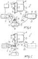
- the machine tool generally designated by the reference numeral 1, comprises a main mandrel 2 which has, in a conventional manner, grip means for a mechanical part 30 to be machined; said mandrel can be rotated in a controlled (indexed) manner by a numeric-control unit 3 about its own axis 2a.
- the machine tool also comprises a first carriage 4 which supports a turret tool post 5 with a plurality of stations (generally twelve) with turning tools and other tools which are motorized independently to perform drilling and/or milling and/or axial and radial thread cutting, in a manner which is similar to that of turret tool posts of conventional numeric-control lathes (CNC).
- stations generally twelve
- CNC numeric-control lathes
- the machine tool also comprises a second carriage 6, which supports a hobbing tool head 7.
- the first carriage 4 and the second carriage 6 can move on command, in a manner which is controlled by the numeric-control controller 3, with respect to the main mandrel 2 in order to selectively move the tools 8, 9, 10 installed on the turret tool post 5 and the hobbing tool 11 installed on the head 7 so that they machine the part 30 supported by the main mandrel 2.
- the first carriage 4 can move on command along two numeric-control axes 12 and 13 with continuous interpolation: a first axis 12, which is parallel to the axis 2a of the main mandrel 2, and a second axis 13, which is perpendicular to the first axis 12.
- the second carriage 6 can also move on command, with respect to the main mandrel 2, along two numeric-control axes 14 and 15 with continuous interpolation: a third axis 14, which is perpendicular to the axis 2a of the main mandrel 2, and a fourth axis 15, which is perpendicular to the third axis 14.
- the hobbing tool 11 can be actuated, with a rotary motion which is controlled by the controller 3, about its own axis 16, which constitutes a fifth numeric-control axis.
- the head 7, which supports the hobbing tools 11, can rotate on command, again in a manner which is controlled by the controller 3, about a sixth numeric-control axis 17, which is perpendicular to the axis 2a of the main mandrel 2 in order to allow to vary the inclination of the hobbing tool 11 with respect to the axis 2a of the main mandrel 2 according to the gear hobbing requirements, i.e., to vary/adjust the inclination of the helix of the hobbing tool with respect to the angle of the teeth of the gears to be cut with respect to the axis of the part 30.
- the head 7 can move on command, with respect to the second carriage 6, in a manner which is controlled by the controller 3, along a seventh numeric-control axis 18 which is parallel to the fourth axis 15.
- the third carriage 19 can move on command, in a manner which is controlled by the controller 3, along two numeric-control axes with continuous interpolation: a ninth axis 21, which is parallel to the axis 2a of the main mandrel 2, and a tenth axis 22, which is perpendicular to the ninth axis 21.
- the tailstock 20 can be constituted, according to the requirements, by an auxiliary mandrel which is provided with means for gripping the part 30 to be machined and can be rotated about its own axis 20a if it is necessary to replace or assist the grip of the part 30 performed by the main mandrel 2, or can be constituted by a tailstock.
- the movements of the components of the machine tool according to the present invention along the various numeric-control axes, as a consequence of the operational interconnection ensured by the controller 3, can be mutually synchronized in the desired relation so as to perform, according to a program which is preset in the numeric-control controller 3, the machinings required to produce the part 30.
- the movement of the first carriage 4 and/or of the second carriage 6 is synchronized with the rotation of the main mandrel 2 and/or of the auxiliary mandrel that constitutes the tailstock 20.
- the rotation of the auxiliary mandrel about its own axis is also conveniently synchronized with the rotation of the main mandrel 2.
- the machine tool can be equipped with devices for unloading the machined part or with other conventional accessories.
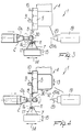
- the part 30 to be machined which is rough-shaped beforehand, is arranged on the main mandrel 2, using the corresponding grip means.
- the controller 3 drives the main mandrel 2 with a rotary motion about its own axis 2a and moves the carriage 4 along the axes 12 and 13, performing the turning or milling or drilling of the part 30, according to the tool being used (figure 2).
- the controller 3 moves the first carriage 4 so as to back off the tools of the turret tool post 4 from the part 30 and moves the second carriage 6 along the axes 14 and 15, the head 7 about the axis 17 and along the axis 18, and actuates the hobbing tool 11 so that it rotates about its own axis 16 to perform the gear hobbing of the part (figure 3).
- the machine tool according to the present invention is capable of producing, by means of the axial movement of the hobbing tool (shifting), gears which are mutually different, not only in their ratio (two or more gears which differ in number of teeth), but also in terms of tooth shape and pitch, by simultaneously installing two or more hobbing tools on the axis of the head 7.
- controller 3 can move the second carriage 6 so as to back off the hobbing tool 11 from the part and again move the first carriage 4 to optionally perform further turning operations (figure 4).
- the part can be supported or machined by the tailstock 20 by means of the movement of the third carriage 19, which is again actuated by the controller 3, along the axes 21 and 22 and about the axis 20a of the tailstock 20.
- the carriages 4 and 6 can machine simultaneously by using the hobbing tool together with another tool of the carriage 4, for example to deburr by skimming the part at the region where the hobbing tool reduces its pressure.
- the machine tool is also capable of chamfering the gear during gear hobbing.
- the machine tool can operate as a "continuous bar” by means of an external bar pusher which continuously feeds commercial bars (3000 mm long).
- an external bar pusher which continuously feeds commercial bars (3000 mm long).
- a cropping operation performed by a tool, followed by unloading of the part and subsequent protrusion of the bar from the main mandrel, preparing the system to machine the next part.
- the machine tool according to the present invention fully achieves the intended aim and objects, since it is capable of performing turning, milling, drilling and hobbing, avoiding the removal and repositioning of the part on various machining units during intermediate steps of machining.
- the integrated machining that can be performed with the machine tool according to the present invention allows to obtain fully finished parts whilst reducing the full cycle related to the individual part, considerably shortening the production cycle and thus allowing better concurrency in the overall cycle.
- the machine tool according to the invention needs no additional gear grip and locking fixtures, which are instead required in conventional machine tools, with drawbacks related to the cost and maintenance of said fixtures.
- Another advantage is the higher machining precision achieved with the machine tool according to the present invention, since the part is free from machining errors arising from imperfect positioning of the part in its transfer from one machine tool to another.
- Another advantage is that it is possible to use oil in a water-based emulsion as lubricant-coolant, as in a normal lathe, instead of the full mineral oil used in gear hobbing machines, with an additional saving in operating costs.
- Another advantage is that it allows considerable economy in terms of labor and energy costs.
- the -materials used, as well as the dimensions, may be any according to requirements and to the state of the art.
Landscapes
- Engineering & Computer Science (AREA)
- Mechanical Engineering (AREA)
- Gear Processing (AREA)
- Numerical Control (AREA)
- Cutting Tools, Boring Holders, And Turrets (AREA)
- Turning (AREA)
Abstract
Description
Claims (13)
- A numeric-control machine tool for turning and hobbing mechanical parts, characterized in that it comprises: a main mandrel, which is provided with grip means for a mechanical part and can be rotated about its own axis; a first carriage, which supports a turret tool post for turning and/or milling and/or drilling; and a second carriage, which supports a gear hobbing tool head; said first and second carriages being movable on command, in a controlled manner, with respect to said main mandrel in order to selectively move the tools installed on said turret tool post and the hobbing tools so that they machine the part supported by said main mandrel.
- A machine tool according to claim 1, characterized in that said first carriage can move on command, with respect to said main mandrel, along two numeric-control axes with continuous interpolation: a first axis, which is parallel to the axis of said main mandrel, and a second axis, which is perpendicular to said first axis.
- A machine tool according to claim 1, characterized in that said second carriage can move on command, with respect to said main mandrel, along two numeric-control axes with continuous interpolation: a third axis, which is parallel to the axis of said main mandrel, and a fourth axis, which is perpendicular to said third axis.
- A machine tool according to claim 1, characterized in that the hobbing tool fitted on said hobbing tool head can rotate on command about a fifth numeric-control axis which coincides with the axis of the hobbing tool.
- A machine tool according to claim 1, characterized in that said hobbing tool head can rotate on command about a sixth numeric-control axis which is perpendicular to the axis of said main mandrel in order to vary the inclination of the hobbing tool with respect to the axis of said main mandrel.
- A machine tool according to claim 3, characterized in that said hobbing tool head can move on command, with respect to said second carriage, along a seventh numeric-control axis which is parallel to said fourth axis.
- A machine tool according to claim 1, characterized in that it comprises a third carriage which supports a tailstock which faces said main mandrel and can be rotated about its own axis, which constitutes an eighth numeric-control axis which is parallel to the axis of said main mandrel.
- A machine tool according to claim 7, characterized in that said third carriage can move on command along two numeric-control axes with continuous interpolation: a ninth axis, which is parallel to the axis of said main mandrel, and a tenth axis, which is perpendicular to said ninth axis.
- A machine tool according to claim 7, characterized in that said tailstock is constituted by an auxiliary mandrel provided with means for gripping the mechanical part to be machined.
- A machine tool according to claim 7, characterized in that said tailstock is constituted by a center.
- A machine tool according to claim 9, characterized in that the rotation of said main mandrel and/or of said auxiliary mandrel about its/their own axis is controlled (indexed) continuously.
- A machine tool according to claim 9, characterized in that the movement of said first carriage and/or of said second carriage is synchronized with the rotation of said main mandrel and/or of said auxiliary mandrel.
- A machine tool according to claim 9, characterized in that the rotation of said auxiliary mandrel about its own axis is synchronized with the rotation of said main mandrel.
Applications Claiming Priority (2)
| Application Number | Priority Date | Filing Date | Title |
|---|---|---|---|
| ITMI961973 | 1996-09-26 | ||
| IT96MI001973A IT1284594B1 (en) | 1996-09-26 | 1996-09-26 | NUMERIC CONTROL MACHINE TOOL FOR THE PERFORMANCE OF TURNING AND TOOTHING MECHANICAL PARTS |
Publications (3)
| Publication Number | Publication Date |
|---|---|
| EP0832716A2 true EP0832716A2 (en) | 1998-04-01 |
| EP0832716A3 EP0832716A3 (en) | 1999-02-03 |
| EP0832716B1 EP0832716B1 (en) | 2002-08-28 |
Family
ID=11374928
Family Applications (1)
| Application Number | Title | Priority Date | Filing Date |
|---|---|---|---|
| EP97116172A Expired - Lifetime EP0832716B1 (en) | 1996-09-26 | 1997-09-17 | Numeric-control machine tool for turning and hobbing mechanical parts |
Country Status (6)
| Country | Link |
|---|---|
| US (1) | US6079090A (en) |
| EP (1) | EP0832716B1 (en) |
| JP (1) | JPH10128626A (en) |
| AT (1) | ATE222833T1 (en) |
| DE (1) | DE69714929T2 (en) |
| IT (1) | IT1284594B1 (en) |
Cited By (10)
| Publication number | Priority date | Publication date | Assignee | Title |
|---|---|---|---|---|
| WO2006084481A1 (en) * | 2005-02-14 | 2006-08-17 | Klingelnberg Gmbh | Device and method for green machining bevel gears |
| WO2007012351A1 (en) * | 2005-07-28 | 2007-02-01 | Klingelnberg Gmbh | Universal machine for the soft machining of bevel gears and corresponding method |
| WO2007046116A1 (en) * | 2005-10-20 | 2007-04-26 | Metalmeccanica Meridionale S.P.A. | Shaping roll for double cold working of sheet material and apparatus and process for realising said roll |
| DE10032123B4 (en) * | 2000-07-05 | 2008-05-29 | Hmp Engineering Gmbh | Device and method for piercing and deburring a circumferential groove in toothed workpieces |
| WO2011095957A1 (en) | 2010-02-08 | 2011-08-11 | Nuova Trasmissione S.R.L. | Multifunction modular machine tool for integrated machining processes |
| CN101670444B (en) * | 2009-09-29 | 2012-06-27 | 东莞市台科精密机械有限公司 | Numerical control lathe |
| WO2012136774A1 (en) * | 2011-04-07 | 2012-10-11 | Mag Modul Verzahntechnik Gmbh | Method for producing toothings on workpieces |
| CN103056629A (en) * | 2012-12-27 | 2013-04-24 | 重庆机床(集团)有限责任公司 | Shaft gear composite processing machine tool |
| WO2014206902A1 (en) * | 2013-06-27 | 2014-12-31 | Felsomat Gmbh & Co. Kg | Hobbing machine having a pivoting arm, on which a chamfering device and at least one cutting tool are arranged |
| CN104588783A (en) * | 2014-12-25 | 2015-05-06 | 绍兴县珂阳五金汽配厂 | Technology for cold rolling extrusion teeth of cylindrical end face |
Families Citing this family (41)
| Publication number | Priority date | Publication date | Assignee | Title |
|---|---|---|---|---|
| JP2001198702A (en) * | 2000-01-12 | 2001-07-24 | Dainichi Kinzoku Kogyo Kk | Multitasking machine |
| US6318221B1 (en) * | 2000-04-04 | 2001-11-20 | Hydra-Seal, Inc. | Apparatus and method for forming sealing rings |
| US20020079022A1 (en) * | 2000-12-27 | 2002-06-27 | Colle Paolo M. | Machining systems and methods for forming non-metallic parts |
| DE10226272A1 (en) * | 2002-06-07 | 2004-01-08 | Index-Werke Gmbh & Co. Kg Hahn & Tessky | Multi-spindle machine tool |
| WO2004091864A2 (en) * | 2003-04-08 | 2004-10-28 | Arvin Joseph L | Apparatus and method for machining workpieces |
| DE10330474B4 (en) * | 2003-07-05 | 2009-03-05 | Fette Gmbh | Device for producing a gear from a gear blank |
| US7188420B2 (en) * | 2004-03-15 | 2007-03-13 | Torque—Traction Technologies, Inc. | Method for manufacturing bevel gears |
| US20090060672A1 (en) * | 2005-02-04 | 2009-03-05 | Fitzgerald Brian M | Multiple Operation Gear Manufacturing Apparatus With Common Work Axis |
| DE102005009893B4 (en) * | 2005-03-01 | 2007-01-11 | Emag Holding Gmbh | Machine tool with at least one tool turret |
| US20070209179A1 (en) * | 2005-04-15 | 2007-09-13 | Mark Williams | Lathe hobbing tool |
| DE202005011790U1 (en) * | 2005-07-22 | 2005-10-20 | Gleason-Pfauter Maschinenfabrik Gmbh | Unit for deburring and creation of chamfer at teeth of bevel wheel, attached to main device for creation of toothed areas |
| RU2385787C2 (en) * | 2005-07-28 | 2010-04-10 | КЛИНГЕЛЬНБЕРГ ГмбХ | Device for manufacturing of conical geared wheels and according method |
| DE102005043104B4 (en) * | 2005-09-10 | 2015-12-17 | Esa Eppinger Gmbh | Device for lubricating bearing points on machine tools or parts thereof |
| CN100421851C (en) * | 2005-11-25 | 2008-10-01 | 王永德 | Prism working mechanism for instrument lathe |
| US7310863B2 (en) * | 2006-02-10 | 2007-12-25 | Gm Global Technology Operations, Inc. | De-burring apparatus for a hobbing machine |
| EP2019911B1 (en) | 2006-05-09 | 2015-04-01 | Hill-Rom Services, Inc. | Pulmonary mattress |
| DE202007010461U1 (en) * | 2007-07-25 | 2008-12-04 | Gleason-Pfauter Maschinenfabrik Gmbh | processing machine |
| ITBO20090373A1 (en) * | 2009-06-09 | 2010-12-10 | Samp Spa Con Unico Socio | GEAR MACHINE FOR PRODUCTION OF GEARS |
| JP5423460B2 (en) * | 2010-02-12 | 2014-02-19 | 株式会社ジェイテクト | Oscillating gear machining method and machine |
| US20110271804A1 (en) * | 2010-05-04 | 2011-11-10 | Chun-Ta Hsieh | Centre drilling/turning tool holder |
| JP5732350B2 (en) * | 2010-11-11 | 2015-06-10 | Dmg森精機株式会社 | Machine Tools |
| CN102248226B (en) * | 2011-06-21 | 2013-01-23 | 南京高速齿轮制造有限公司 | Numerical-control combined gear milling and hobbing machine for machining large-modulus gear and application thereof |
| CN102303219B (en) * | 2011-08-12 | 2013-02-27 | 天津第一机床总厂 | Machining method for worm tooth profile of cutter shaft of large gear shaping machine |
| JP2012030360A (en) * | 2011-09-30 | 2012-02-16 | Klingelnberg Gmbh | Universal machine for soft machining of bevel gear and corresponding method |
| DE102011084975A1 (en) | 2011-10-21 | 2013-04-25 | Mag Ias Gmbh | Machine tool for rotating and toothing shaft, has processing unit including rolling milling head, which is arranged in suspended state and linearly moved in relation to frame in z-direction and x2-direction |
| US9228885B2 (en) | 2012-06-21 | 2016-01-05 | Hill-Rom Services, Inc. | Patient support systems and methods of use |
| WO2013192411A2 (en) | 2012-06-21 | 2013-12-27 | Meyer Eric R | Patient support systems and methods of use |
| US9833369B2 (en) | 2012-06-21 | 2017-12-05 | Hill-Rom Services, Inc. | Patient support systems and methods of use |
| DE102013003290A1 (en) * | 2013-02-26 | 2014-08-28 | Gleason-Pfauter Maschinenfabrik Gmbh | Method for machining or machining a toothing and gear cutting machine |
| JP6314066B2 (en) * | 2014-09-08 | 2018-04-18 | Dmg森精機株式会社 | Machine Tools |
| CN105619076A (en) * | 2014-10-28 | 2016-06-01 | 富鼎电子科技(嘉善)有限公司 | Combined machining device |
| JP2016153149A (en) * | 2015-02-20 | 2016-08-25 | ファナック株式会社 | Machine tool having lathe tool holder mounting unit |
| CN204603788U (en) * | 2015-03-27 | 2015-09-02 | 大连誉洋工业智能有限公司 | Intelligent grinding and cutting system |
| CN204621767U (en) * | 2015-03-27 | 2015-09-09 | 大连誉洋工业智能有限公司 | Intelligent Cutting System |
| JP6794868B2 (en) * | 2017-02-20 | 2020-12-02 | アイシン精機株式会社 | Combined gear cutting equipment |
| US10662520B2 (en) | 2017-03-29 | 2020-05-26 | Applied Materials, Inc. | Method for recycling substrate process components |
| JP7167631B2 (en) * | 2018-10-30 | 2022-11-09 | 株式会社ジェイテクト | Machine tool and gear machining method using machine tool |
| CN111015098B (en) * | 2019-12-04 | 2020-12-22 | 北京北方车辆集团有限公司 | A high-precision combined frame intelligent manufacturing method |
| KR102550321B1 (en) * | 2020-02-24 | 2023-07-03 | (주)대성하이텍 | Gear shaft integrated gear processing system |
| CN111360548A (en) * | 2020-04-26 | 2020-07-03 | 武汉伍点伍科技有限公司 | Multifunctional gear hobbing machine for turning, milling and drilling |
| CN112157932B (en) * | 2020-09-22 | 2022-04-08 | 厦门健康伦自动仪器有限公司 | A processing technology to ensure the concentricity of inner and outer circles in the processing of plastic transmission gears |
Family Cites Families (8)
| Publication number | Priority date | Publication date | Assignee | Title |
|---|---|---|---|---|
| DE1652728B2 (en) * | 1968-02-23 | 1973-03-15 | Werkzeugmaschinen Fabrik Gildemei ster & Co, AG, 4800 Bielefeld | CURVELESS PROGRAM CONTROLLED FOUR-SPINDLE AUTOMATIC LATHE WITH HORIZONTALLY MOUNTED SPINDLE DRUM |
| US3685111A (en) * | 1968-12-18 | 1972-08-22 | Seiko Seiki Kk | Multi-spindle automatic bar machine |
| JPS56337A (en) * | 1979-06-08 | 1981-01-06 | Hayakawa Textile Ind | Production of antiistatic wool product |
| US4543020A (en) * | 1983-05-16 | 1985-09-24 | Usm Corporation | Method of manufacturing large gears |
| JPH04269137A (en) * | 1991-02-20 | 1992-09-25 | Tsugami Corp | Composite work machine tool |
| DE59104722D1 (en) * | 1991-10-19 | 1995-03-30 | Index Werke Kg Hahn & Tessky | Lathe. |
| CN1072541C (en) * | 1995-02-06 | 2001-10-10 | 邵文远 | Small integrated machining center |
| US5885199A (en) * | 1996-02-06 | 1999-03-23 | Shao; Wenyuan | Compact machining center for multifunction |
-
1996
- 1996-09-26 IT IT96MI001973A patent/IT1284594B1/en active IP Right Grant
-
1997
- 1997-09-17 EP EP97116172A patent/EP0832716B1/en not_active Expired - Lifetime
- 1997-09-17 AT AT97116172T patent/ATE222833T1/en active
- 1997-09-17 JP JP9251912A patent/JPH10128626A/en active Pending
- 1997-09-17 DE DE69714929T patent/DE69714929T2/en not_active Expired - Lifetime
- 1997-09-19 US US08/933,881 patent/US6079090A/en not_active Expired - Lifetime
Cited By (20)
| Publication number | Priority date | Publication date | Assignee | Title |
|---|---|---|---|---|
| DE10032123B4 (en) * | 2000-07-05 | 2008-05-29 | Hmp Engineering Gmbh | Device and method for piercing and deburring a circumferential groove in toothed workpieces |
| WO2006084481A1 (en) * | 2005-02-14 | 2006-08-17 | Klingelnberg Gmbh | Device and method for green machining bevel gears |
| US8151437B2 (en) | 2005-02-14 | 2012-04-10 | Klingelnberg Gmbh | Device and method for green machining bevel gears |
| WO2007012351A1 (en) * | 2005-07-28 | 2007-02-01 | Klingelnberg Gmbh | Universal machine for the soft machining of bevel gears and corresponding method |
| CN101374622B (en) * | 2005-07-28 | 2011-06-08 | 科林基恩伯格股份有限公司 | Universal machine and method for soft processing bevel wheel |
| US8707528B2 (en) | 2005-07-28 | 2014-04-29 | Klingelnberg Gmbh | Universal machine for the soft machining of bevel gears and corresponding method |
| WO2007046116A1 (en) * | 2005-10-20 | 2007-04-26 | Metalmeccanica Meridionale S.P.A. | Shaping roll for double cold working of sheet material and apparatus and process for realising said roll |
| CN101670444B (en) * | 2009-09-29 | 2012-06-27 | 东莞市台科精密机械有限公司 | Numerical control lathe |
| KR20120139735A (en) * | 2010-02-08 | 2012-12-27 | 누오바 트라스미시오네 에스.알.엘. | Multifunction modular machine tool for integrated machining processes |
| CN102821911A (en) * | 2010-02-08 | 2012-12-12 | 诺瓦传输股份公司 | Modular multifunctional machine tools for comprehensive machining processes |
| WO2011095957A1 (en) | 2010-02-08 | 2011-08-11 | Nuova Trasmissione S.R.L. | Multifunction modular machine tool for integrated machining processes |
| CN102821911B (en) * | 2010-02-08 | 2016-02-10 | 诺瓦传输股份公司 | Modular multifunctional machine tools for comprehensive machining processes |
| WO2012136774A1 (en) * | 2011-04-07 | 2012-10-11 | Mag Modul Verzahntechnik Gmbh | Method for producing toothings on workpieces |
| CN103608144A (en) * | 2011-04-07 | 2014-02-26 | 美格工业自动化系统有限公司 | Method for producing gears on workpieces |
| US9346112B2 (en) | 2011-04-07 | 2016-05-24 | Mag Ias Gmbh | Method for producing toothed sections on workpieces |
| CN103056629A (en) * | 2012-12-27 | 2013-04-24 | 重庆机床(集团)有限责任公司 | Shaft gear composite processing machine tool |
| CN103056629B (en) * | 2012-12-27 | 2015-11-18 | 重庆机床(集团)有限责任公司 | Shaft gear composite processing machine tool |
| WO2014206902A1 (en) * | 2013-06-27 | 2014-12-31 | Felsomat Gmbh & Co. Kg | Hobbing machine having a pivoting arm, on which a chamfering device and at least one cutting tool are arranged |
| CN104588783A (en) * | 2014-12-25 | 2015-05-06 | 绍兴县珂阳五金汽配厂 | Technology for cold rolling extrusion teeth of cylindrical end face |
| CN104588783B (en) * | 2014-12-25 | 2017-05-31 | 绍兴县珂阳五金汽配厂 | The technique that a kind of cylindrical end face cold breakdown extrudes tooth |
Also Published As
| Publication number | Publication date |
|---|---|
| IT1284594B1 (en) | 1998-05-21 |
| DE69714929T2 (en) | 2003-04-30 |
| DE69714929D1 (en) | 2002-10-02 |
| US6079090A (en) | 2000-06-27 |
| ITMI961973A1 (en) | 1998-03-26 |
| JPH10128626A (en) | 1998-05-19 |
| EP0832716A3 (en) | 1999-02-03 |
| EP0832716B1 (en) | 2002-08-28 |
| ATE222833T1 (en) | 2002-09-15 |
Similar Documents
| Publication | Publication Date | Title |
|---|---|---|
| EP0832716B1 (en) | Numeric-control machine tool for turning and hobbing mechanical parts | |
| EP0500104B1 (en) | Composite-machining machine tool | |
| US5885199A (en) | Compact machining center for multifunction | |
| US5490307A (en) | Lathe | |
| EP2533940B1 (en) | Multifunction modular machine tool for integrated machining processes | |
| EP0614406B1 (en) | Gear hobbing machine | |
| CN101811206B (en) | Device for rolling off a workpiece clamped in a tool machine and method for producing a workpiece comprising cogged tools | |
| US9914180B2 (en) | Method for producing and/or processing a gear and gear cutting machine | |
| JP5100652B2 (en) | Combined lathe and its tool post | |
| US9358627B2 (en) | Method for machining a workpiece | |
| EP0810048A1 (en) | A compact machine centre for multifunction | |
| US4739684A (en) | Apparatus for finishing pistons and the like and method therefor | |
| US20120152069A1 (en) | CNC MACHINES, ADJUSTABLE TOOLS FOR CNC MACHINES, AND METHODS of OPERATING AN ADJUSTABLE TOOL ON A CNC MACHINE | |
| EP0046883A2 (en) | Multiple spindle rotary indexing machine tool | |
| US4867020A (en) | Apparatus for finishing pistons and the like and method therefor | |
| US5159741A (en) | Machine for the machining of metal | |
| US2096754A (en) | Machine tool | |
| US5735029A (en) | Flexible arbor mill machine | |
| JP2782290B2 (en) | Multi-tasking machine with automatic tool changer | |
| JPH02279202A (en) | Work machining device for 2 main shafts facing type cnc lathe | |
| US4614467A (en) | Cam milling machine | |
| CN118951891A (en) | A turning and milling compound CNC lathe with a powered turret | |
| CN121972914A (en) | Nuclear island driving rod integrated processing and manufacturing method | |
| KR20080047363A (en) | Universal machine for soft machining of bevel gear and its countermeasure | |
| JPH05345202A (en) | Composite nc lathe |
Legal Events
| Date | Code | Title | Description |
|---|---|---|---|
| PUAI | Public reference made under article 153(3) epc to a published international application that has entered the european phase |
Free format text: ORIGINAL CODE: 0009012 |
|
| AK | Designated contracting states |
Kind code of ref document: A2 Designated state(s): AT CH DE ES FR GB IT LI |
|
| AX | Request for extension of the european patent |
Free format text: AL;LT;LV;RO;SI |
|
| PUAL | Search report despatched |
Free format text: ORIGINAL CODE: 0009013 |
|
| AK | Designated contracting states |
Kind code of ref document: A3 Designated state(s): AT BE CH DE DK ES FI FR GB GR IE IT LI LU MC NL PT SE |
|
| AX | Request for extension of the european patent |
Free format text: AL;LT;LV;RO;SI |
|
| 17P | Request for examination filed |
Effective date: 19990729 |
|
| AKX | Designation fees paid |
Free format text: AT CH DE ES FR GB IT LI |
|
| 17Q | First examination report despatched |
Effective date: 20001031 |
|
| GRAG | Despatch of communication of intention to grant |
Free format text: ORIGINAL CODE: EPIDOS AGRA |
|
| GRAG | Despatch of communication of intention to grant |
Free format text: ORIGINAL CODE: EPIDOS AGRA |
|
| GRAH | Despatch of communication of intention to grant a patent |
Free format text: ORIGINAL CODE: EPIDOS IGRA |
|
| GRAH | Despatch of communication of intention to grant a patent |
Free format text: ORIGINAL CODE: EPIDOS IGRA |
|
| RAP1 | Party data changed (applicant data changed or rights of an application transferred) |
Owner name: IMMOBILIARE LINDA S.N.C. DI STEFANO ONGARO E LINDA |
|
| GRAA | (expected) grant |
Free format text: ORIGINAL CODE: 0009210 |
|
| AK | Designated contracting states |
Kind code of ref document: B1 Designated state(s): AT CH DE ES FR GB IT LI |
|
| REF | Corresponds to: |
Ref document number: 222833 Country of ref document: AT Date of ref document: 20020915 Kind code of ref document: T |
|
| REG | Reference to a national code |
Ref country code: GB Ref legal event code: FG4D |
|
| REG | Reference to a national code |
Ref country code: CH Ref legal event code: EP |
|
| REG | Reference to a national code |
Ref country code: CH Ref legal event code: NV Representative=s name: PATENTANWALTSBUERO EDER AG |
|
| REF | Corresponds to: |
Ref document number: 69714929 Country of ref document: DE Date of ref document: 20021002 |
|
| ET | Fr: translation filed | ||
| PG25 | Lapsed in a contracting state [announced via postgrant information from national office to epo] |
Ref country code: ES Free format text: LAPSE BECAUSE OF FAILURE TO SUBMIT A TRANSLATION OF THE DESCRIPTION OR TO PAY THE FEE WITHIN THE PRESCRIBED TIME-LIMIT Effective date: 20030228 |
|
| PLBE | No opposition filed within time limit |
Free format text: ORIGINAL CODE: 0009261 |
|
| STAA | Information on the status of an ep patent application or granted ep patent |
Free format text: STATUS: NO OPPOSITION FILED WITHIN TIME LIMIT |
|
| 26N | No opposition filed |
Effective date: 20030530 |
|
| PGFP | Annual fee paid to national office [announced via postgrant information from national office to epo] |
Ref country code: GB Payment date: 20060919 Year of fee payment: 10 |
|
| GBPC | Gb: european patent ceased through non-payment of renewal fee |
Effective date: 20070917 |
|
| PG25 | Lapsed in a contracting state [announced via postgrant information from national office to epo] |
Ref country code: GB Free format text: LAPSE BECAUSE OF NON-PAYMENT OF DUE FEES Effective date: 20070917 |
|
| REG | Reference to a national code |
Ref country code: FR Ref legal event code: PLFP Year of fee payment: 20 |
|
| PGFP | Annual fee paid to national office [announced via postgrant information from national office to epo] |
Ref country code: AT Payment date: 20160930 Year of fee payment: 20 Ref country code: FR Payment date: 20160929 Year of fee payment: 20 |
|
| PGFP | Annual fee paid to national office [announced via postgrant information from national office to epo] |
Ref country code: DE Payment date: 20160929 Year of fee payment: 20 Ref country code: CH Payment date: 20161020 Year of fee payment: 20 |
|
| PGFP | Annual fee paid to national office [announced via postgrant information from national office to epo] |
Ref country code: IT Payment date: 20160927 Year of fee payment: 20 |
|
| REG | Reference to a national code |
Ref country code: DE Ref legal event code: R071 Ref document number: 69714929 Country of ref document: DE |
|
| REG | Reference to a national code |
Ref country code: CH Ref legal event code: PL |
|
| REG | Reference to a national code |
Ref country code: AT Ref legal event code: MK07 Ref document number: 222833 Country of ref document: AT Kind code of ref document: T Effective date: 20170917 |