EP0832710B1 - Welding method in the overhead and vertical positions - Google Patents
Welding method in the overhead and vertical positions Download PDFInfo
- Publication number
- EP0832710B1 EP0832710B1 EP97116571A EP97116571A EP0832710B1 EP 0832710 B1 EP0832710 B1 EP 0832710B1 EP 97116571 A EP97116571 A EP 97116571A EP 97116571 A EP97116571 A EP 97116571A EP 0832710 B1 EP0832710 B1 EP 0832710B1
- Authority
- EP
- European Patent Office
- Prior art keywords
- welding
- welding method
- current
- overhead
- parent material
- Prior art date
- Legal status (The legal status is an assumption and is not a legal conclusion. Google has not performed a legal analysis and makes no representation as to the accuracy of the status listed.)
- Expired - Lifetime
Links
- 238000003466 welding Methods 0.000 title claims description 87
- 238000000034 method Methods 0.000 title claims description 21
- 239000000463 material Substances 0.000 claims description 23
- 230000001939 inductive effect Effects 0.000 claims 1
- 239000011324 bead Substances 0.000 description 10
- 229910052751 metal Inorganic materials 0.000 description 8
- 239000002184 metal Substances 0.000 description 8
- 230000000694 effects Effects 0.000 description 5
- 230000004907 flux Effects 0.000 description 3
- 230000005484 gravity Effects 0.000 description 3
- 239000004020 conductor Substances 0.000 description 2
- 238000010894 electron beam technology Methods 0.000 description 2
- 230000004927 fusion Effects 0.000 description 2
- 238000004519 manufacturing process Methods 0.000 description 2
- 229910000831 Steel Inorganic materials 0.000 description 1
- 230000001133 acceleration Effects 0.000 description 1
- 239000000470 constituent Substances 0.000 description 1
- 230000007547 defect Effects 0.000 description 1
- 230000002950 deficient Effects 0.000 description 1
- 230000008021 deposition Effects 0.000 description 1
- 238000010586 diagram Methods 0.000 description 1
- 239000007789 gas Substances 0.000 description 1
- 238000010438 heat treatment Methods 0.000 description 1
- 239000011261 inert gas Substances 0.000 description 1
- 230000007246 mechanism Effects 0.000 description 1
- 230000008018 melting Effects 0.000 description 1
- 238000002844 melting Methods 0.000 description 1
- 238000007493 shaping process Methods 0.000 description 1
- 239000010959 steel Substances 0.000 description 1
- WFKWXMTUELFFGS-UHFFFAOYSA-N tungsten Chemical compound [W] WFKWXMTUELFFGS-UHFFFAOYSA-N 0.000 description 1
- 229910052721 tungsten Inorganic materials 0.000 description 1
- 239000010937 tungsten Substances 0.000 description 1
Images




Classifications
-
- B—PERFORMING OPERATIONS; TRANSPORTING
- B23—MACHINE TOOLS; METAL-WORKING NOT OTHERWISE PROVIDED FOR
- B23K—SOLDERING OR UNSOLDERING; WELDING; CLADDING OR PLATING BY SOLDERING OR WELDING; CUTTING BY APPLYING HEAT LOCALLY, e.g. FLAME CUTTING; WORKING BY LASER BEAM
- B23K9/00—Arc welding or cutting
- B23K9/08—Arrangements or circuits for magnetic control of the arc
-
- B—PERFORMING OPERATIONS; TRANSPORTING
- B23—MACHINE TOOLS; METAL-WORKING NOT OTHERWISE PROVIDED FOR
- B23K—SOLDERING OR UNSOLDERING; WELDING; CLADDING OR PLATING BY SOLDERING OR WELDING; CUTTING BY APPLYING HEAT LOCALLY, e.g. FLAME CUTTING; WORKING BY LASER BEAM
- B23K9/00—Arc welding or cutting
- B23K9/06—Arrangements or circuits for starting the arc, e.g. by generating ignition voltage, or for stabilising the arc
- B23K9/073—Stabilising the arc
- B23K9/0737—Stabilising of the arc position
Definitions
- This invention concerns a welding method in the overhead and vertical positions wherein a parent material is melted using a specified heat source to form a molten pool and there is a possibility that the aforesaid molten pool will experience deformation under the influence of gravity. More specifically, it concerns a welding method in the overhead and vertical positions to be used in the production of large structures such as bridges, pressure vessels or the like.
- the flat position refers to welding a virtually horizontal joint from below, facing an upward direction.
- the "flat position” refers to a horizontal joint being welded from above, facing downward.
- the "horizontal position” refers to welding horizontally a joint whose axis of weld is virtually horizontal.
- the “vertical position” refers to welding the length of a joint whose axis of weld is vertical.
- US-A-1914518 discloses a welding apparatus wherein a magnetic flux is employed to improve the welding quality in combination with a current flow through the welding wire and welding material.
- the welding device Even if this welding process is automated, the welding device must have the same level of capability as a skilled worker who performs the process discussed above. A number of webbing mechanisms and close control of heat will be necessary. Since these are not always enough, the welding process must be conducted at a low temperature with low efficiency. This stands in the way of making the welding process more efficient.
- the object of the present invention is to provide a welding method in the overhead and vertical positions which would avoid the problem detailed above and which would enable high-efficiency welding.
- the present invention provides the welding method according to claim 1.
- a heat source which may be an arc, a laser, or an electron beam to form a molten pool
- the aforesaid pool tends to become deformed due to the effect of gravity.
- An electric current is made to flow in the aforesaid molten pool in virtually the same direction as the weld line.
- a magnetic field is also given in the aforesaid molten pool orthogonal to the direction of the aforesaid current, that is to say, orthogonal to the weld line and parallel to the surface of the parent material. While welding is executed, a Lorentz force is thereby exerted in the aforesaid molten pool, in an upward direction in the groove.
- a unidirectional current A is generated in molten pool 12.
- Magnetic field 9 is also given parallel to the surface of the parent material and perpendicular to the weld line. This causes a Lorentz force to be exerted in an upward direction in the groove. Under this force, a weld bead is achieved which does not drip downward.
- FIG 1 shows a welding device employing a welding method which is an ideal embodiment of the present invention.
- This is a method for MAG (metal active gas) welding in the overhead and vertical positions using an arc (heat source 10), and a consumable electrode 13 (the welding wire).
- MAG metal active gas
- the welding power supply 1 an ordinary welding power supply is used.
- Arc 10 the heat source
- the heat of this arc causes parent material 7 to melt.
- the conductive material chosen for the auxiliary wires should be one which is compatible with the material of the joint.
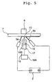
- External permanent magnet or DC electromagnet 6 is placed so as to induce a magnetic field 9 near the rear surface of parent material 7 (the upper top side of the groove) which is perpendicular to the weld line and parallel to the surface of the parent material as seen from welding torch 4. (See Figure 8 for position of magnet.)
- this scheme enhances the efficiency of the process by preventing the molten metal from dripping down the surface of the parent material.
- auxiliary wires 5a and 5b Just as with TIG (tungsten inert gas) hot-wire welding methods used in the prior art, running current through auxiliary wires 5a and 5b causes a Joule effect heating of those wires, which in turn increases their rate of deposition.
- TIG tungsten inert gas
- the appropriate range of the welding conditions is as follows: The welding current is between 100 and 300 A; the arc voltage is between 12 and 27 V; the welding speed is between 5 and 20 cm/min; the magnetic flux density is between 38 and 300 Gauss; and the current between the auxiliary wires is between 70 and 200 A.
- the range of values for the welding current is that in which the movement of the drop and the shaping of the bead can be accomplished in a stable fashion.
- the range for the arc voltage is that in which the arc can be maintained in a stable fashion when the aforesaid welding current is within its specified range.
- the range of welding speed is that in which the proper volume is deposited per unit of welding length with respect to the given welding current.
- the range of magnetic flux density is that needed to generate the electromagnetic force required to improve the shape of the bead and maintain the arc in a stable fashion.
- the range of current between the auxiliary wires is that in which the amount of electromagnetic force needed to improve the shape of the bead can be generated and in which the wires melt in a stable fashion.
- the welding conditions described above may vary depending on the diameter and material of the consumable electrode and auxiliary wires which are used, and the shape, material, etc. of the parent material.
- laser processor 16 comprises YAG or CO 2 laser oscillator 16A and main unit 16B which uses condenser lens 15 to condense laser beam 17.
- the YAG or CO 2 laser is used as the heat source for welding, and auxiliary wires 5a and 5b are placed so as to generate a unidirectional current in the direction of the weld line.
- the only current flowing in molten pool 12 is that between wires 5a and 5b, so the same result is achieved as in Embodiment 1.
- a YAG laser is used with an output of 4.5 KW, an electron beam acceleration voltage of 60 KV, and a beam current of 10 mA. In this embodiment, only the auxiliary wires are used as the filling metal.
- the arc current is generally unidirectional in the direction opposite the welding direction, even without the use of separate means such as auxiliary wires to create a unidirectional current. (See Figure 8.) Thus the same effect can be achieved as in Embodiment 1.
- Permanent or electromagnet 6 is shaped like a flattened horseshoe with poles 6N and 6S on either end. It is placed so that it straddles groove 21 on the side of upper surface 21A, with poles 6N and 6S on either side of the gap between the two segments of parent material 7. This arrangement allows a magnetic field to be applied which is parallel to parent material 7 and orthogonal to the weld line.
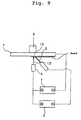
- FIG 9 shows a TIG welding device.
- TIG welding also, a unidirectional current is generated along the welding direction between nonconsumable electrode 13' and auxiliary wire 5 just as in Figure 4. This allows the same result to be achieved as in Embodiment 1.
- only the auxiliary wire is used as the source of fill metal.
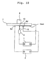
- MAG welding as shown in Figure 10, a set of two Cu feeder element 5a' and Cu collector element 5b' are placed ahead of and behind the welding location. If a unidirectional current is made to flow between the collector elements, the same result is achieved as in Embodiment 1.
- the collector elements move as a single entity with the welding torch.
Landscapes
- Engineering & Computer Science (AREA)
- Physics & Mathematics (AREA)
- Plasma & Fusion (AREA)
- Mechanical Engineering (AREA)
- Arc Welding Control (AREA)
- Butt Welding And Welding Of Specific Article (AREA)
- Arc Welding In General (AREA)
- Generation Of Surge Voltage And Current (AREA)
- Laser Beam Processing (AREA)
Description
A YAG laser is used with an output of 4.5 KW, an electron beam acceleration voltage of 60 KV, and a beam current of 10 mA. In this embodiment, only the auxiliary wires are used as the filling metal.
Claims (7)
- A welding method to weld a parent material (7, 22) having a groove (21) in overhead or vertical positions, comprising a step of: generating a unidirectional current flow (A) in a molten pool (10, 12) along a direction of a weld line; and inducing a magnetic field (9) in said molten pool parallel to a surface of said parent material and orthogonal to said direction of said weld line to exert a Lorentz force (11) in an upward direction of said groove,
wherein said unidirectional current flow (A) is generated by a set of feeder and collector elements (5a-5b, 5, 13, 5a'-5b') which are positioned along said direction of said weld line and are inserted into said molten pool. - A welding method according to claim 1, wherein said set of feeder and collector elements moves with a welding torch (4).
- A welding method according to claim 1 or 2, wherein said unidirectional current (A) is a split current of a welding current which is split by a diverter (8).
- A welding method according to any of claims 1 to 3, wherein said magnetic field (9) is induced by a permanent magnet (6).
- A welding method according to claim 4, wherein said permanent magnet (6) is positioned at a rear side of said parent material (7, 22), which is the opposite side from a welding torch (4).
- A welding method according to any of claims 1 to 3, wherein said magnetic field (9) is induced by a DC electromagnet (6).
- A welding method according to claim 6, wherein said DC electromagnet (6) is positioned at a rear side of said parent material (7, 22), which is the opposite side from a welding torch (4).
Priority Applications (1)
| Application Number | Priority Date | Filing Date | Title |
|---|---|---|---|
| EP01128735A EP1231009B1 (en) | 1996-09-26 | 1997-09-23 | Welding method in the overhead position |
Applications Claiming Priority (3)
| Application Number | Priority Date | Filing Date | Title |
|---|---|---|---|
| JP27555996A JP3530322B2 (en) | 1996-09-26 | 1996-09-26 | Upward / vertical welding method |
| JP275559/96 | 1996-09-26 | ||
| JP27555996 | 1996-09-26 |
Related Child Applications (2)
| Application Number | Title | Priority Date | Filing Date |
|---|---|---|---|
| EP01128735A Division EP1231009B1 (en) | 1996-09-26 | 1997-09-23 | Welding method in the overhead position |
| EP01128735.6 Division-Into | 2001-12-03 |
Publications (2)
| Publication Number | Publication Date |
|---|---|
| EP0832710A1 EP0832710A1 (en) | 1998-04-01 |
| EP0832710B1 true EP0832710B1 (en) | 2003-05-02 |
Family
ID=17557142
Family Applications (2)
| Application Number | Title | Priority Date | Filing Date |
|---|---|---|---|
| EP97116571A Expired - Lifetime EP0832710B1 (en) | 1996-09-26 | 1997-09-23 | Welding method in the overhead and vertical positions |
| EP01128735A Expired - Lifetime EP1231009B1 (en) | 1996-09-26 | 1997-09-23 | Welding method in the overhead position |
Family Applications After (1)
| Application Number | Title | Priority Date | Filing Date |
|---|---|---|---|
| EP01128735A Expired - Lifetime EP1231009B1 (en) | 1996-09-26 | 1997-09-23 | Welding method in the overhead position |
Country Status (4)
| Country | Link |
|---|---|
| US (1) | US5932121A (en) |
| EP (2) | EP0832710B1 (en) |
| JP (1) | JP3530322B2 (en) |
| DE (2) | DE69735906T2 (en) |
Cited By (1)
| Publication number | Priority date | Publication date | Assignee | Title |
|---|---|---|---|---|
| DE102010018354A1 (en) | 2010-04-27 | 2011-10-27 | Mansfeld Anlagenbau Und Umwelttechnik Ag | Influencing weld pool in a weld seam, comprises stimulating a quickly changeable magnetic field, whose field lines are directed transversely to a direction of the weld seam |
Families Citing this family (30)
| Publication number | Priority date | Publication date | Assignee | Title |
|---|---|---|---|---|
| DE10128793B4 (en) * | 2001-06-15 | 2005-08-25 | Universität Stuttgart Institut für Strahlwerkzeuge | Method for processing a workpiece with a laser beam |
| DE10225781B4 (en) * | 2002-06-10 | 2006-07-27 | Universität Stuttgart Institut für Strahlwerkzeuge | Method for treating, in particular for welding, a workpiece with a high energy beam |
| US7032312B2 (en) * | 2002-07-16 | 2006-04-25 | Calsonickansei North America, Inc. | Catalytic converter and method for manufacture thereof |
| RU2288821C2 (en) * | 2004-07-30 | 2006-12-10 | ЗАО "Уралтермосвар" | Electric arc welding process of vertical seam by up-down method with use of coated electrode |
| DE102004039916A1 (en) * | 2004-08-18 | 2006-03-09 | Universität Stuttgart Institut für Strahlwerkzeuge | Narrow recess production in metal workpiece comprises subjecting workpiece to high energy stream, e.g. electron or laser beam, used in cutting, boring and structuring workpieces with action of Lorenze force and magnetic field on melt |
| DE102007028956A1 (en) | 2007-06-22 | 2008-12-24 | Ruchay, Wilfried, Dipl.-Ing. | Method for weld pool manipulation, particularly for vertical weld seams with weld gap, involves creating magnetic field during welding of root seam in area around weld pool |
| US20090120916A1 (en) * | 2007-11-12 | 2009-05-14 | L3 Communications Corporation | Through-Via Laser Reflow Systems And Methods For Surface Mount Components |
| US10086461B2 (en) | 2009-01-13 | 2018-10-02 | Lincoln Global, Inc. | Method and system to start and use combination filler wire feed and high intensity energy source for welding |
| US9085041B2 (en) | 2009-01-13 | 2015-07-21 | Lincoln Global, Inc. | Method and system to start and use combination filler wire feed and high intensity energy source for welding |
| US20130213942A1 (en) * | 2009-01-13 | 2013-08-22 | Lincoln Global, Inc. | Method and system for laser welding and cladding with multiple consumables |
| JP5326632B2 (en) * | 2009-02-16 | 2013-10-30 | マツダ株式会社 | Laser welding method and laser welding apparatus |
| CN103042306B (en) * | 2011-10-12 | 2015-06-03 | 中国科学院力学研究所 | Method for measuring effects of gravity on laser welded joint welded seam shapes |
| US20130136940A1 (en) * | 2011-11-28 | 2013-05-30 | General Electric Company | Welding system, welding process, and welded article |
| US9862050B2 (en) | 2012-04-03 | 2018-01-09 | Lincoln Global, Inc. | Auto steering in a weld joint |
| US10239145B2 (en) * | 2012-04-03 | 2019-03-26 | Lincoln Global, Inc. | Synchronized magnetic arc steering and welding |
| US20140008332A1 (en) * | 2012-07-06 | 2014-01-09 | Lincoln Global, Inc. | Method and system of using gas flow to control weld puddle in out-of-position welding |
| US20140034621A1 (en) * | 2012-08-03 | 2014-02-06 | Lincoln Global, Inc. | Method and system of hot wire joint design for out-of-position welding |
| US10035211B2 (en) * | 2013-03-15 | 2018-07-31 | Lincoln Global, Inc. | Tandem hot-wire systems |
| US10086465B2 (en) * | 2013-03-15 | 2018-10-02 | Lincoln Global, Inc. | Tandem hot-wire systems |
| WO2014155180A2 (en) * | 2013-03-25 | 2014-10-02 | Lincoln Global, Inc. | Method and system for laser welding and cladding with multiple consumables |
| CN103143848B (en) * | 2013-03-26 | 2015-05-20 | 哈尔滨工业大学(威海) | Vertical welding method for applying ultrasonic-arc hybrid |
| US10464168B2 (en) | 2014-01-24 | 2019-11-05 | Lincoln Global, Inc. | Method and system for additive manufacturing using high energy source and hot-wire |
| DE202014011237U1 (en) * | 2014-07-26 | 2018-09-18 | Hermann Von Rautenkranz Internationale Tiefbohr Gmbh & Co Kg - Itag | Device for build-up welding |
| EP3034225B1 (en) | 2014-12-17 | 2018-10-17 | Airbus Defence and Space GmbH | Method and apparatus for distortion control on additively manufactured parts using wire and magnetic pulses |
| WO2018159857A1 (en) * | 2017-03-03 | 2018-09-07 | 古河電気工業株式会社 | Welding method and welding device |
| US11027362B2 (en) | 2017-12-19 | 2021-06-08 | Lincoln Global, Inc. | Systems and methods providing location feedback for additive manufacturing |
| CN108247226B (en) * | 2018-01-24 | 2020-09-01 | 北京工业大学 | Laser welding pool control method based on Lorentz force |
| CN108817712B (en) * | 2018-08-30 | 2021-01-05 | 哈尔滨工业大学(威海) | Magnetic control hot wire swinging laser welding device, method and application |
| US11123826B1 (en) * | 2020-03-11 | 2021-09-21 | Jiangsu University | Electromagnetic apparatus for active intervention to shape of molten pool |
| CN111822825A (en) * | 2020-07-15 | 2020-10-27 | 北京博清科技有限公司 | Upward welding process for plates |
Family Cites Families (4)
| Publication number | Priority date | Publication date | Assignee | Title |
|---|---|---|---|---|
| US1914518A (en) * | 1932-02-09 | 1933-06-20 | Martin Charles Warren | Welding apparatus |
| NL96499C (en) * | 1952-07-05 | 1900-01-01 | ||
| US4190760A (en) * | 1976-05-14 | 1980-02-26 | Kobe Steel, Ltd. | Welding apparatus with shifting magnetic field |
| JP2778920B2 (en) * | 1994-11-11 | 1998-07-23 | 三菱重工業株式会社 | Lateral welding method and lateral welding device |
-
1996
- 1996-09-26 JP JP27555996A patent/JP3530322B2/en not_active Expired - Lifetime
-
1997
- 1997-09-23 DE DE69735906T patent/DE69735906T2/en not_active Expired - Lifetime
- 1997-09-23 DE DE69721421T patent/DE69721421T2/en not_active Expired - Lifetime
- 1997-09-23 EP EP97116571A patent/EP0832710B1/en not_active Expired - Lifetime
- 1997-09-23 EP EP01128735A patent/EP1231009B1/en not_active Expired - Lifetime
- 1997-09-24 US US08/937,116 patent/US5932121A/en not_active Expired - Lifetime
Cited By (1)
| Publication number | Priority date | Publication date | Assignee | Title |
|---|---|---|---|---|
| DE102010018354A1 (en) | 2010-04-27 | 2011-10-27 | Mansfeld Anlagenbau Und Umwelttechnik Ag | Influencing weld pool in a weld seam, comprises stimulating a quickly changeable magnetic field, whose field lines are directed transversely to a direction of the weld seam |
Also Published As
| Publication number | Publication date |
|---|---|
| JPH1099966A (en) | 1998-04-21 |
| EP1231009B1 (en) | 2006-05-17 |
| JP3530322B2 (en) | 2004-05-24 |
| EP0832710A1 (en) | 1998-04-01 |
| DE69721421D1 (en) | 2003-06-05 |
| US5932121A (en) | 1999-08-03 |
| DE69735906D1 (en) | 2006-06-22 |
| DE69735906T2 (en) | 2006-12-21 |
| DE69721421T2 (en) | 2004-03-11 |
| EP1231009A2 (en) | 2002-08-14 |
| EP1231009A3 (en) | 2002-12-11 |
Similar Documents
| Publication | Publication Date | Title |
|---|---|---|
| US5932121A (en) | Welding method in the overhead and vertical positions | |
| EP0844039B1 (en) | Horizontal welding method and welding equipment | |
| JPWO1997043073A1 (en) | Horizontal welding method and welding equipment | |
| US4904843A (en) | AC TIG welding apparatus using hot wire | |
| CN101421069B (en) | Metal cored electrode for open root pass welding | |
| KR100841822B1 (en) | Submerged Arc Welding Weaving Device | |
| US4190760A (en) | Welding apparatus with shifting magnetic field | |
| CN108994427B (en) | Control method of DC welding arc magnetic deflection blowing using external magnetic field expansion device | |
| CN107949451A (en) | Welding method and arc-welding apparatus | |
| JP2778920B2 (en) | Lateral welding method and lateral welding device | |
| JP2005095953A (en) | Tig welding method and device | |
| JP3867164B2 (en) | Welding method | |
| JP2000079469A (en) | Welding method and welding equipment | |
| CN109954959A (en) | A single power source double arc shunt type submerged arc welding method | |
| JPH0320310B2 (en) | ||
| JPH0663754A (en) | Gas shield arc welding method | |
| JPH0635061B2 (en) | Narrow groove TIG welding equipment | |
| JP3349390B2 (en) | Electrogas arc welding method and apparatus for horizontal position | |
| CA1085466A (en) | Utilizing a magnetic field | |
| JPS5927779A (en) | Gas metal arc welding method | |
| JPH0747474A (en) | Horizontal 1-layer multi-pass welding method | |
| JPH0359785B2 (en) | ||
| JPS6045034B2 (en) | DC TIG weaving welding method | |
| JPS5827035B2 (en) | Overlay welding method using a strip electrode | |
| JPS6149776A (en) | Horizontal narrow gap welding method |
Legal Events
| Date | Code | Title | Description |
|---|---|---|---|
| PUAI | Public reference made under article 153(3) epc to a published international application that has entered the european phase |
Free format text: ORIGINAL CODE: 0009012 |
|
| AK | Designated contracting states |
Kind code of ref document: A1 Designated state(s): DE FR GB |
|
| AX | Request for extension of the european patent |
Free format text: AL;LT;LV;RO;SI |
|
| 17P | Request for examination filed |
Effective date: 19980514 |
|
| AKX | Designation fees paid |
Free format text: DE FR GB |
|
| RBV | Designated contracting states (corrected) |
Designated state(s): DE FR GB |
|
| 17Q | First examination report despatched |
Effective date: 20000406 |
|
| GRAG | Despatch of communication of intention to grant |
Free format text: ORIGINAL CODE: EPIDOS AGRA |
|
| GRAG | Despatch of communication of intention to grant |
Free format text: ORIGINAL CODE: EPIDOS AGRA |
|
| GRAH | Despatch of communication of intention to grant a patent |
Free format text: ORIGINAL CODE: EPIDOS IGRA |
|
| GRAH | Despatch of communication of intention to grant a patent |
Free format text: ORIGINAL CODE: EPIDOS IGRA |
|
| GRAA | (expected) grant |
Free format text: ORIGINAL CODE: 0009210 |
|
| AK | Designated contracting states |
Designated state(s): DE FR GB |
|
| REG | Reference to a national code |
Ref country code: GB Ref legal event code: FG4D |
|
| GRAH | Despatch of communication of intention to grant a patent |
Free format text: ORIGINAL CODE: EPIDOS IGRA |
|
| REF | Corresponds to: |
Ref document number: 69721421 Country of ref document: DE Date of ref document: 20030605 Kind code of ref document: P |
|
| REG | Reference to a national code |
Ref country code: GB Ref legal event code: 746 Effective date: 20031111 |
|
| ET | Fr: translation filed | ||
| PLBE | No opposition filed within time limit |
Free format text: ORIGINAL CODE: 0009261 |
|
| STAA | Information on the status of an ep patent application or granted ep patent |
Free format text: STATUS: NO OPPOSITION FILED WITHIN TIME LIMIT |
|
| 26N | No opposition filed |
Effective date: 20040203 |
|
| PGFP | Annual fee paid to national office [announced via postgrant information from national office to epo] |
Ref country code: DE Payment date: 20100915 Year of fee payment: 14 |
|
| PGFP | Annual fee paid to national office [announced via postgrant information from national office to epo] |
Ref country code: GB Payment date: 20110921 Year of fee payment: 15 Ref country code: FR Payment date: 20110922 Year of fee payment: 15 |
|
| GBPC | Gb: european patent ceased through non-payment of renewal fee |
Effective date: 20120923 |
|
| REG | Reference to a national code |
Ref country code: FR Ref legal event code: ST Effective date: 20130531 |
|
| REG | Reference to a national code |
Ref country code: DE Ref legal event code: R119 Ref document number: 69721421 Country of ref document: DE Effective date: 20130403 |
|
| PG25 | Lapsed in a contracting state [announced via postgrant information from national office to epo] |
Ref country code: GB Free format text: LAPSE BECAUSE OF NON-PAYMENT OF DUE FEES Effective date: 20120923 Ref country code: DE Free format text: LAPSE BECAUSE OF NON-PAYMENT OF DUE FEES Effective date: 20130403 |
|
| PG25 | Lapsed in a contracting state [announced via postgrant information from national office to epo] |
Ref country code: FR Free format text: LAPSE BECAUSE OF NON-PAYMENT OF DUE FEES Effective date: 20121001 |